WO2024181217A1 - 走行支援システム、経路作成方法 - Google Patents
走行支援システム、経路作成方法 Download PDFInfo
- Publication number
- WO2024181217A1 WO2024181217A1 PCT/JP2024/005887 JP2024005887W WO2024181217A1 WO 2024181217 A1 WO2024181217 A1 WO 2024181217A1 JP 2024005887 W JP2024005887 W JP 2024005887W WO 2024181217 A1 WO2024181217 A1 WO 2024181217A1
- Authority
- WO
- WIPO (PCT)
- Prior art keywords
- work
- field
- slope
- work vehicle
- control unit
- Prior art date
- Legal status (The legal status is an assumption and is not a legal conclusion. Google has not performed a legal analysis and makes no representation as to the accuracy of the status listed.)
- Ceased
Links
Images








Classifications
-
- A—HUMAN NECESSITIES
- A01—AGRICULTURE; FORESTRY; ANIMAL HUSBANDRY; HUNTING; TRAPPING; FISHING
- A01B—SOIL WORKING IN AGRICULTURE OR FORESTRY; PARTS, DETAILS, OR ACCESSORIES OF AGRICULTURAL MACHINES OR IMPLEMENTS, IN GENERAL
- A01B69/00—Steering of agricultural machines or implements; Guiding agricultural machines or implements on a desired track
- A01B69/007—Steering or guiding of agricultural vehicles, e.g. steering of the tractor to keep the plough in the furrow
- A01B69/008—Steering or guiding of agricultural vehicles, e.g. steering of the tractor to keep the plough in the furrow automatic
-
- A—HUMAN NECESSITIES
- A01—AGRICULTURE; FORESTRY; ANIMAL HUSBANDRY; HUNTING; TRAPPING; FISHING
- A01B—SOIL WORKING IN AGRICULTURE OR FORESTRY; PARTS, DETAILS, OR ACCESSORIES OF AGRICULTURAL MACHINES OR IMPLEMENTS, IN GENERAL
- A01B69/00—Steering of agricultural machines or implements; Guiding agricultural machines or implements on a desired track
-
- A—HUMAN NECESSITIES
- A01—AGRICULTURE; FORESTRY; ANIMAL HUSBANDRY; HUNTING; TRAPPING; FISHING
- A01B—SOIL WORKING IN AGRICULTURE OR FORESTRY; PARTS, DETAILS, OR ACCESSORIES OF AGRICULTURAL MACHINES OR IMPLEMENTS, IN GENERAL
- A01B79/00—Methods for working soil
- A01B79/005—Precision agriculture
-
- G—PHYSICS
- G01—MEASURING; TESTING
- G01C—MEASURING DISTANCES, LEVELS OR BEARINGS; SURVEYING; NAVIGATION; GYROSCOPIC INSTRUMENTS; PHOTOGRAMMETRY OR VIDEOGRAMMETRY
- G01C21/00—Navigation; Navigational instruments not provided for in groups G01C1/00 - G01C19/00
- G01C21/04—Navigation; Navigational instruments not provided for in groups G01C1/00 - G01C19/00 by terrestrial means
- G01C21/06—Navigation; Navigational instruments not provided for in groups G01C1/00 - G01C19/00 by terrestrial means involving measuring of drift angle; involving correction for drift
-
- G—PHYSICS
- G05—CONTROLLING; REGULATING
- G05D—SYSTEMS FOR CONTROLLING OR REGULATING NON-ELECTRIC VARIABLES
- G05D1/00—Control of position, course, altitude or attitude of land, water, air or space vehicles, e.g. using automatic pilots
- G05D1/40—Control within particular dimensions
- G05D1/43—Control of position or course in two dimensions [2D]
- G05D1/435—Control of position or course in two dimensions [2D] resulting in a change of level, e.g. negotiating lifts or stairs
-
- G—PHYSICS
- G05—CONTROLLING; REGULATING
- G05D—SYSTEMS FOR CONTROLLING OR REGULATING NON-ELECTRIC VARIABLES
- G05D1/00—Control of position, course, altitude or attitude of land, water, air or space vehicles, e.g. using automatic pilots
- G05D1/60—Intended control result
- G05D1/646—Following a predefined trajectory, e.g. a line marked on the floor or a flight path
-
- G—PHYSICS
- G05—CONTROLLING; REGULATING
- G05D—SYSTEMS FOR CONTROLLING OR REGULATING NON-ELECTRIC VARIABLES
- G05D1/00—Control of position, course, altitude or attitude of land, water, air or space vehicles, e.g. using automatic pilots
- G05D1/60—Intended control result
- G05D1/65—Following a desired speed profile
-
- G—PHYSICS
- G05—CONTROLLING; REGULATING
- G05D—SYSTEMS FOR CONTROLLING OR REGULATING NON-ELECTRIC VARIABLES
- G05D2105/00—Specific applications of the controlled vehicles
- G05D2105/15—Specific applications of the controlled vehicles for harvesting, sowing or mowing in agriculture or forestry
-
- G—PHYSICS
- G05—CONTROLLING; REGULATING
- G05D—SYSTEMS FOR CONTROLLING OR REGULATING NON-ELECTRIC VARIABLES
- G05D2107/00—Specific environments of the controlled vehicles
- G05D2107/20—Land use
- G05D2107/21—Farming, e.g. fields, pastures or barns
-
- G—PHYSICS
- G05—CONTROLLING; REGULATING
- G05D—SYSTEMS FOR CONTROLLING OR REGULATING NON-ELECTRIC VARIABLES
- G05D2109/00—Types of controlled vehicles
- G05D2109/10—Land vehicles
Definitions
- the present invention relates to a technology for turning a work vehicle on a slope.
- the area setting unit widens the headland width to increase the turning radius of the work vehicle or slows down the vehicle speed when the slope of the headland in the travel direction of the work vehicle exceeds a threshold value, compared to when the slope is equal to or less than the threshold value.
- the present invention aims to enable a work vehicle to turn stably on slopes.
- the driving assistance system includes a route creation device having an input unit to which slope information of a slope is input, and a control unit that determines a boundary direction by tilting the slope direction of the slope identified from the slope information by a predetermined angle to the left and right toward the slope direction, and creates a turning route for a slope that turns the work vehicle on the slope so that only the centrifugal force toward a restricted range extending from the boundary direction to the top of the slope acts on the work vehicle.
- the control unit may change the predetermined angle according to the slope angle of the slope identified from the slope information.
- the control unit may create the turning path for the sloping ground so that, of a virtual circumference based on the intersection of the slope direction of the sloping ground and the boundary direction, a lower arc located outside the restricted range is not included, but an upper arc located within the restricted range is included.
- the input unit inputs field information indicating the field, device information of the work device coupled to the work vehicle, and working conditions for work performed by the work device while the work vehicle is traveling in the field, and the control unit creates, on a field map indicating the field, multiple work paths along which the work vehicle is traveled to perform work using the work device, based on the field information, the device information, and the working conditions, and may create, on the field map, a slope turning path for turning the work vehicle from one of the work paths to the other of the work paths when it determines, based on the slope information of the field included in the field information, that the field is a slope that slopes within a predetermined angle range.
- control unit may create a predetermined normal turning path on the field map for turning the work vehicle from one of the work paths to the other of the work paths.
- the control unit may identify the contour, inclination direction, and inclination angle of the field from the field information, identify the working direction and headland width from the working conditions, identify the working width of the working equipment from the equipment information, set a headland and a central area located inside the headland on the field map based on the contour and headland width of the field, create multiple work paths in the central area of the field map based on the working direction and the working width, and create the sloping ground turning path on the headland or across the headland and the central area of the field map based on the inclination direction, inclination angle, and working direction of the field.
- the control unit may create the turning path for sloping ground when the inclination angle of the field identified from the inclination information is within the predetermined angle range and the azimuth difference between the inclination direction of the field identified from the inclination information and the work direction identified from the work conditions is equal to or less than a predetermined value, and may cancel the creation of the turning path for sloping ground when the inclination angle is greater than the predetermined angle range and when the azimuth difference is greater than the predetermined value even if the inclination angle is within the predetermined angle range.
- control unit determines that the field is a slope based on the slope information of the field, it may determine the order in which the work vehicle will travel along the multiple work paths based on the slope direction and slope angle of the field identified from the slope information, and create the turning path for slopes according to the order of travel.
- the path creation device may have a memory unit that stores multiple types of turning patterns for the work vehicle, and when the control unit determines that the field is sloping, it may select one of the multiple types of turning patterns based on the slope direction of the field identified from the slope information and the distance between one of the work paths and the other of the work paths, and create the sloping ground turning path with the selected turning pattern.
- the control unit may determine from the field information which sloped areas in the field and the field map are inclined within a predetermined angle range and which are not inclined or are inclined at an angle smaller than the predetermined angle range, and may create a sloping turning path for turning the work vehicle from one of the work paths to the other of the work paths at the sloped areas of the field map, and may create a predetermined normal turning path for turning the work vehicle from one of the work paths to the other of the work paths at the non-sloped areas of the field map.
- the driving assistance system may include the work vehicle and a display device that displays the turning path for sloping terrain.
- the work vehicle may have a vehicle body capable of running, a position detection device that detects the position of the vehicle body, and a control device that executes an automatic running mode in which the vehicle body is steered and run automatically based on the multiple work routes, the sloping turning route or the normal turning route output from an output unit provided in the route creation device, and the vehicle body position detected by the position detection device.
- the work vehicle may have the route creation device, and the control device may perform work using a work device connected to the vehicle body while automatically steering and driving the vehicle body based on the sloping turning route output from the route creation device and the position of the vehicle body detected by the position detection device.
- the control unit may create a plurality of the work paths before the automatic driving mode is executed and output the plurality of work paths to the control device by the output unit, and may create the sloping ground turning path or the normal turning path based on the slope information of the field before or during the automatic driving mode is executed and output the sloping ground turning path or the normal turning path to the control device by the output unit.
- a route creation method is a route creation method for creating a route along which a work vehicle travels, and includes the steps of: inputting slope information of a slope to a route creation device by an input unit; and determining a boundary direction by a control unit of the route creation device tilting the slope direction of the slope identified from the slope information by a predetermined angle to the left and right toward the slope direction, and creating a turning route for a slope that turns the work vehicle on the slope so that only centrifugal force toward a restricted range extending from the boundary direction toward the upper part of the slope acts on the work vehicle.
- the present invention allows a work vehicle to turn stably on slopes.
- FIG. 1 is a configuration diagram of a driving assistance system.
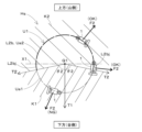
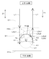
- FIG. 4 is a diagram showing centrifugal forces acting on a work vehicle.
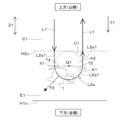
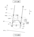
- FIG. FIG. 4 is a diagram showing a limit range of centrifugal force acting on a work vehicle.
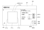
- FIG. 13 is a diagram showing a route creation screen.
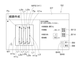
- FIG. 13 is a diagram showing a route creation screen after a travel route is created.
- FIG. 13 is a diagram showing a driving control screen.
- 13 is a flowchart showing a procedure for creating a work route.
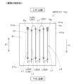
- FIG. 13 is a diagram showing an example of a work route.
- 13 is a flowchart showing a procedure for creating a turning path.
- FIG. 13 is a diagram showing an example of a normal turning path when a farm field is equivalent to flat land.
- FIG. 8B is an enlarged view of the normal turning path of FIG. 8A.
- FIG. 13 is a diagram showing an example of a turning path for use on sloping ground when the farm field is on a slope.
- FIG. 9B is a close-up view of the sloped terrain turn path above the slope of FIG. 9A.
- FIG. 9B is a close-up view of the sloped terrain turn path below the slope of FIG. 9A.
- FIG. 13 is a diagram showing an example of a normal turning path when a farm field is on a slope.
- FIG. 10B is an enlarged view of a normal turning path below the inclined direction of FIG. 10A.
- FIG. 13 is a diagram showing an example of a turning path for sloping ground when the working direction is inclined relative to the inclination direction of the field.
- FIG. 11 is a diagram showing another example of a turning path for use on sloping ground when the farm field is on a slope.
- FIG. 13 is a diagram showing an example of a turning path for sloping ground in which the work vehicle extends beyond the field.
- FIG. 13 is a diagram showing an example of a turning path for sloping ground that does not extend beyond the field.
- FIG. 13 is a diagram showing an example of a turning path for sloping ground when the headland width of a farm field is expanded.
- FIG. 1 is a diagram showing an example of a turning path for sloping ground that spans the headland and central area of a farm field.
- 13A and 13B are diagrams showing other examples of turning paths for slopes when the working direction is inclined relative to the slope direction of the field.
- FIG. 13 is a diagram showing an example of a turning path for use on sloping ground when the inclination direction of the field and the working direction are perpendicular to each other.
- FIG. 18B is an enlarged view of the sloped terrain turning path of FIG. 18A.
- 1 is a diagram showing an example of a turning path for sloping ground when the inclination direction of the field and the working direction are parallel and the interval between the working paths is narrow.
- FIG. 13A and 13B are diagrams showing other examples of turning paths for use on sloping ground when the inclination direction of the field and the working direction are perpendicular to each other.
- FIG. 13 is a diagram showing an example of a sloping turning path created in a sloping portion of a farm field and a normal turning path created in a non-sloping portion.
- FIG. 22 is a side view of the work vehicle 1.
- the work vehicle 1 is composed of a tractor.
- the work vehicle of the present invention is not limited to a tractor, and may be composed of other drivable work vehicles such as a rice transplanter or a combine harvester, construction machinery, or other work vehicles.
- the work vehicle 1 includes a vehicle body 3, a prime mover 4, a transmission 5, and a traveling device 7.
- the front wheels 7F and rear wheels 7R included in the traveling device 7 may be of the tire type or crawler type.
- the prime mover 4 is composed of a diesel engine or an electric motor. In this embodiment, the prime mover 4 is composed of a diesel engine.
- the transmission 5 can switch the propulsive force of the traveling device 7 by changing gears, and can also switch the traveling device 7 between forward and reverse.
- the driving force of the prime mover 4 is transmitted to the traveling device 7 by the transmission 5, and the traveling device 7 is driven, causing the vehicle body 3 to travel forward and backward.
- the left side is the front of the work vehicle 1 (vehicle body 3), and the right side is the rear of the work vehicle 1.
- the back side is the right side of the work vehicle 1
- the front side is the left side of the work vehicle 1.
- the vehicle body 3 of the work vehicle 1 is provided with a cabin 9. Inside the cabin 9, a driver's seat 10 is provided.
- a lifting device 8 consisting of a three-point linkage mechanism or the like is provided at the rear of the vehicle body 3.
- a work device 2 for performing agricultural work can be connected to the lifting device 8.
- the work device 2 can be connected to coupling parts 8g, 8h provided on the lifting device 8.
- the work device 2 and the work vehicle 1 (vehicle body 3) are connected, and the work vehicle 1 can tow the work device 2.
- a directly mounted work device that is directly mounted on the vehicle body 3 of the work vehicle 1 may be applied.
- the working device 2 may be, for example, a tilling device (rotary tiller) for tilling the field, a spraying device for spraying fertilizer or pesticides, a soil cultivating device (also called a ridge making device) for cultivating soil, a sowing device for sowing crop seeds, a transplanting device for transplanting seedlings, or a harvesting device for harvesting crops.
- a tilling device rotary tiller
- a spraying device for spraying fertilizer or pesticides
- a soil cultivating device also called a ridge making device
- sowing device for sowing crop seeds
- transplanting device for transplanting seedlings
- harvesting device for harvesting crops for harvesting crops.
- FIG. 1 is a configuration diagram of a driving assistance system 100.
- the driving assistance system 100 includes a work vehicle 1 and a route creation device 50.
- the driving assistance system 100 and the route creation device 50 support the driving of the work vehicle 1 and agricultural work performed by the work device 2.
- the work vehicle 1 is equipped with a control device 60, an operating device 62, a prime mover 4, a transmission 5, a braking device 6, a steering device 29, a lifting device 8, a position detection device 40, an alarm device 63, and a status detection device 64.
- the work vehicle 1 also has an in-vehicle network N1 such as a LAN or CAN.
- the control device 60, the operating device 62, the position detection device 40, the alarm device 63, and the status detection device 64 are connected to the in-vehicle network N1.
- Each of these parts provided in the work vehicle 1 is included in the driving assistance system 100.
- the control device 60 is composed of an electronic control unit (ECU) that includes a CPU and internal memory.
- the internal memory of the control device 60 includes volatile memory and non-volatile memory.
- the control device 60 controls the operation of each part of the work vehicle 1 based on software programs and control data stored in the internal memory.
- the control device 60 is a controller that controls the travel of the work vehicle 1 and the operation of the work device 2.
- the operating device 62 is composed of switches, levers, pedals, and other keys that can be operated by an operator such as a driver seated in the driver's seat 10 or a worker near the work vehicle 1.
- the prime mover 4 (engine) is controlled by the control device 60 to drive, stop, and rotate at a specific speed.
- the transmission 5 is connected to a control valve 37.
- the control valve 37 is an electromagnetic valve that operates based on a control signal sent from the control device 60.
- the control valve 37 is supplied with hydraulic oil discharged from the hydraulic pump 33.
- the control valve 37 is shown as one block in FIG. 1, an appropriate number of control valves 37 are provided according to the number of hydraulic devices, such as hydraulic clutches or hydraulic cylinders, provided in the transmission 5.
- the braking device 6 is connected to a control valve 38.
- the control valve 38 is an electromagnetic valve that operates based on a control signal sent from a control device 60.
- the control valve 38 is supplied with hydraulic oil discharged from the hydraulic pump 33.
- the control device 60 electrically controls the switching position and opening degree of the control valve 38 to operate the braking device 6 and apply the brakes to the vehicle body 3.
- the control device 60 electrically controls the switching position (opening) of the control valve 37 to control the drive of the transmission 5.
- the transmission 5 transmits the driving force of the prime mover 4 to the traveling device 7, which operates the traveling device 7 and causes the vehicle body 3 to travel forward and backward.
- the transmission 5 transmits the driving force of the prime mover 4 to the working device 2. This increases the operating force of the working device 2.
- the control device 60 also communicates with the work device 2 via the in-vehicle network N1.
- the work device 2 is equipped with a control unit and a communication unit (not shown).
- the control device 60 transmits a work command to the work device 2 via the in-vehicle network N1.
- the control unit of the work device 2 receives the work command via the communication unit, it controls the operation of each unit of the work device 2 based on the work command to perform agricultural work (ground work).
- the control unit of the work device 2 also transmits information or data indicating the work status, etc. to the control device 60 via the in-vehicle network N1 by the communication unit.
- the control device 60 detects the work status, etc. of the work device 2 based on the information or data received from the work device 2 via the in-vehicle network N1.
- control device 60 does not communicate via the in-vehicle network N1, but controls the operation of the working device 2 by changing the position of the working device 2 by raising and lowering the working device 2 using the lifting device 8 as described below, and detects the working state of the working device 2, etc.
- the steering device 29 has a handle (steering wheel) 30, a steering shaft (rotating shaft) 31, and an auxiliary mechanism (power steering mechanism) 32.
- the handle 30 is provided inside the cabin 9 ( Figure 22).
- the steering shaft 31 rotates in conjunction with the rotation of the handle 30.
- the auxiliary mechanism 32 assists steering by the handle 30.
- the auxiliary mechanism 32 includes a control valve 34 and a steering cylinder 35.
- the control valve 34 is an electromagnetic valve that operates based on a control signal sent from the control device 60. More specifically, the control valve 34 is composed of a three-position switching valve that can be switched by moving a spool or the like.
- the control valve 34 is supplied with hydraulic oil discharged from the hydraulic pump 33.
- the control device 60 electrically controls the switching position and opening degree of the control valve 34 to adjust the hydraulic pressure supplied to the steering cylinder 35, thereby extending and retracting the steering cylinder 35.
- the steering cylinder 35 is connected to a knuckle arm 39 that changes the direction of the front wheels 7F.
- the control valve 34 can also be switched by steering the steering shaft 31. Specifically, by operating the steering wheel 30, the steering shaft 31 rotates according to the operating state, and the switching position and opening degree of the control valve 34 are changed.
- the steering cylinder 35 expands and contracts to the left or right of the vehicle body 3 according to the switching position and opening degree of the control valve 34. The expansion and contraction movement of this steering cylinder 35 changes the steering direction of the front wheels 7F.
- the steering device 29 described above is an example, and is not limited to the above-mentioned configuration.
- the vehicle body 3 of the work vehicle 1 can be manually steered by manually operating the steering wheel 30, or automatically steered by the control device 60.
- the vehicle body 3 can run and stop by operating the transmission 5 or the brake device 6 in response to manual operation of the accelerator member or brake pedal (both not shown) provided on the operation device 62.
- the vehicle body 3 can also run and stop automatically in response to control of the transmission 5 and the brake device 6 by the control device 60. That is, the work vehicle 1 is capable of manual driving in which the operator performs driving and steering operations, automatic driving in which the control device 60 automatically performs driving and steering, and autosteer control (also called automatic steering control or semi-automatic driving) in which the control device 60 automatically performs steering and the operator performs driving operations.
- autosteer control also called automatic steering control or semi-automatic driving
- the lifting device 8 is provided with a hydraulic cylinder as an actuator.
- the hydraulic cylinder is connected to a control valve 36.
- the control valve 36 is an electromagnetic valve that operates based on a control signal sent from the control device 60.
- the control valve 36 is supplied with hydraulic oil discharged from the hydraulic pump 33.
- the control device 60 electrically controls the switching position or opening of the control valve 36 to adjust the hydraulic pressure supplied to the hydraulic cylinder of the lifting device 8 and expand and contract the hydraulic cylinder.
- the connecting parts 8g, 8h Figure 22
- the working device 2 connected to the connecting parts 8g, 8h rises and falls up and down.
- the position detection device 40 shown in FIG. 1 has a receiving device 41 and an inertial measurement unit (IMU) 42.
- the receiving device 41 receives satellite signals (position of the positioning satellite, transmission time, etc.) transmitted from a satellite positioning system (positioning satellite) such as GPS, GLONASS, Beidou, Galileo, and Michibiki.
- the position detection device 40 detects the current position (e.g., latitude, longitude) based on the satellite signal received by the receiving device 41.
- the position detection device 40 is a positioning device that detects the position of the work vehicle 1 (body 3) using the satellite positioning system.
- the inertial measurement device 42 has an acceleration sensor and a gyro sensor, etc.
- the inertial measurement device 42 detects the roll angle, pitch angle, yaw angle, etc. of the body 3.
- the alarm device 63 is composed of a buzzer, speaker, warning light, etc. provided on the body 3.
- the alarm device 63 issues an alarm using sound or light to the area around the vehicle body 3.
- the state detection device 64 is composed of sensors and the like installed in each part of the work vehicle 1 and the working device 2.
- the state detection device 64 detects the operating state (driving and stopped states, operating positions, etc.) of each part of the work vehicle 1, such as the transmission 5, braking device 6, traveling device 7, lifting device 8, steering device 29, and operating device 62, based on output signals from the sensors and the like.
- the state detection device 64 also detects the operating state of the working device 2 based on output signals from the sensors and the like.
- the state detection device 64 also detects the rotation speed of the rear wheel 7R or the traveling motor (not shown) included in the traveling device 7 based on output signals from the sensors and the like, and calculates the vehicle speed (traveling speed) of the work vehicle 1 (body 3) from the rotation speed.
- the condition detection device 64 also includes an object detection unit 64a, a laser sensor such as LiDAR, an ultrasonic sensor, a camera, etc.
- the laser sensor, ultrasonic sensor, camera, etc. are installed at the front, rear, left and right sides of the vehicle body 3.
- the object detection unit 64a detects the presence or absence of objects around the work vehicle 1 and work device 2 and the distance to the objects from the output signal from the laser sensor or ultrasonic sensor.
- the object detection unit 64a also detects the presence or absence of objects around the work vehicle 1 and work device 2 from the captured image of the surroundings of the work vehicle 1 and work device 2 captured by the camera. That is, the condition detection device 64 detects the condition around the work vehicle 1 using the laser sensor, ultrasonic sensor, camera, etc.
- the route creation device 50 is composed of, for example, a portable tablet terminal device.
- the route creation device 50 is mounted, for example, inside the cabin 9 of the work vehicle 1, and is detachable from the work vehicle 1.
- the work vehicle 1 is equipped with the route creation device 50.
- the route creation device 50 can also be detached from the work vehicle 1.
- the route creation device 50 includes a control unit 51, a display operation unit 52, a storage unit 53, and a communication unit 54.
- the control unit 51 is the processor of the route creation device 50, and includes a CPU and an internal memory.
- the internal memory of the control unit 51 includes a volatile memory and a non-volatile memory.
- the display operation unit 52 is composed of a touch panel display and displays various information on the screen. Various information or instructions are input by the operator performing predetermined operations on the display screen of the display operation unit 52.
- the display operation unit 52 is a display device, an output unit (output interface), and an input unit (input interface) of the route creation device 50.
- the display operation unit 52 is also a user interface. Instead of the display operation unit 52, an independent display device, an output interface, and an input interface may be provided in the route creation device 50.
- the memory unit 53 is composed of a non-volatile memory, etc. Information or data that supports the travel of the work vehicle 1 and the work performed by the work device 2 is stored in a readable and writable manner in the memory unit 53.
- the control unit 51 controls each part of the route creation device 50 based on the software programs and control data stored in the memory unit 53 or the internal memory.
- the communication unit 54 is composed of communication interfaces for connecting to the in-vehicle network N1 and an external communication network such as the Internet.
- the control unit 51 communicates with the control device 60, operation device 62, position detection device 40, alarm device 63, status detection device 64, and work device 2 via the in-vehicle network N1 using the communication unit 54.
- the control unit 51 also communicates with external devices via the external communication network using the communication unit 54 to send and receive information to and from the external devices.
- the communication unit 54 is an output unit and input unit that inputs and outputs (sends and receives) information, data, and instructions to and from the work vehicle 1 or external devices.
- Field information indicating the field, vehicle information indicating the work vehicle 1, equipment information indicating the work equipment 2, and working conditions for agricultural work performed by the work equipment 2 while the work vehicle 1 is traveling in the field, etc. are input to the route creation device 50 by the display operation unit 52 or the communication unit 54, respectively, and stored in the internal memory of the memory unit 53 or the control unit 51.
- the control unit 51 creates a travel route for the work vehicle 1, including a work route along which the work vehicle 1 travels to perform agricultural work using the work equipment 2, and a turning route along which the work vehicle 1 turns, based on at least the field information, equipment information, and working conditions.
- the field information includes the field's identification information, position (coordinates), contour, area, and slope information.
- the slope information includes the field's slope direction, slope angle (gradient), and the altitude of each part of the field.
- the equipment information includes information indicating the specifications of the work equipment 2 (including dimensions, performance, identification information, etc.).
- the work conditions include the type of agricultural work, work direction, and headland width.
- the vehicle information of the work vehicle 1 includes information indicating the specifications of the work vehicle 1 (including dimensions, performance, identification information, etc.).
- the vehicle information of the work vehicle 1 is also stored in a memory provided inside the control device 60.
- the control unit 51 may create a travel route for the work vehicle 1 based on the vehicle information of the work vehicle 1 in addition to the field information, equipment information, and work conditions.
- centripetal force F1 toward the turning center Q1 and a centrifugal force F2 toward the opposite direction to the centripetal force F1 act on the work vehicle 1.
- the absolute values of the centripetal force F1 and the centrifugal force F2 are the same.
- the absolute values of the centripetal force F1 and the centrifugal force F2 when the work vehicle 1 is performing uniform circular motion can be calculated by the following formula (1).
- the control unit 51 creates a turning path for slopes that turns the work vehicle 1 on the slope Hs and limits the direction of the centrifugal force F2 acting on the work vehicle 1.
- control unit 51 determines the inclination direction T1 and inclination angle (the inclination angle of the slope Hs with respect to the horizontal line HL, i.e., the gradient) ⁇ 1 of the slope Hs from the inclination information of the slope Hs input by the display operation unit 52 or the like.
- the control unit 51 also determines a pair of left and right boundary directions T2 by tilting the inclination direction T1 by a specific acute angle ⁇ 2 to the left and right toward the inclination direction T1, for example, as shown in FIG. 2C.
- the control unit 51 also determines a prohibited range K1 that extends below the boundary direction T2 on the slope Hs (slope direction T1), and a restricted range K2 that extends from the boundary direction T2 above the slope Hs (slope direction T1).
- the boundary direction T2 is included in the restricted range K2.
- the control unit 51 also changes the specific angle ⁇ 2 according to at least one of the inclination direction T1 and the inclination angle ⁇ 1 of the slope Hs. As a result, the boundary direction T2 and the restricted range K2 are determined according to the inclination state of the slope Hs.
- the control unit 51 creates a turning path L2b for sloping ground (see FIG. 9A, etc., described later) so that the turning path L2b for sloping ground does not include any part of the lower arc Ua1 located in the prohibited range K1 (outside the restricted range K2) of the virtual circumference U1 based (centered) on the intersection Q1 between the slope direction T1 of the slope Hs and the boundary direction T2, but includes at least a part of the upper arc Ua2 located within the restricted range K2.
- the turning path L2b for sloping ground shown in FIG. 2C is the same as the upper arc Ua2.
- the centrifugal force F2 toward the prohibited range K1 does not act on the work vehicle 1, and only the centrifugal force F2 toward the restricted range K2 acts on the work vehicle 1.
- the centrifugal force F2 toward the bottom (valley side) of the slope Hs hardly acts on the work vehicle 1
- the centrifugal force F2 toward the top (mountain side) of the slope Hs mainly acts on the work vehicle 1.
- Both ends L2bj (shown as T2bj in FIG. 2C) of the sloping terrain turning path L2b (upper arc Ua2) are located below the center Q1 in the tilt direction T1. Therefore, when the work vehicle 1 turns along the ends L2bj, a downward centrifugal force F2 in the tilt direction T1 acts on the work vehicle 1. However, at the ends L2bj, if the centrifugal force acting on the work vehicle 1 is decomposed into a downward force and a contour direction in the tilt direction T1, the centrifugal force acting downward in the tilt direction T1 is very weak. Therefore, even if a downward centrifugal force F2 in the tilt direction T1 acts on the work vehicle 1 at the ends L2bj, the work vehicle 1 will not overturn.
- the control unit 51 creates a slope turning path L2b that turns the work vehicle 1 in the field and restricts the direction of the centrifugal force F2 acting on the work vehicle 1 based on the field inclination information. Also, if the field is not inclined or is a non-sloping field (flat or very gently sloping, i.e. equivalent to flat ground) that is inclined at an angle smaller than the predetermined angle range, the control unit 51 creates a predetermined normal turning path L2a (see FIG. 8A, etc., described later) that turns the work vehicle 1 in the field.
- the normal turning path L2a is a turning path that does not restrict the direction of the centrifugal force F2 acting on the work vehicle 1.
- the control unit 51 transmits information (data) such as the field information, equipment information, working conditions, and travel route to the control device 60 of the work vehicle 1 via the communication unit 54.
- the control device 60 controls the drive of the prime mover 4, the transmission 5, the braking device 6, the steering device 29, the lifting device 8, and the work device 2 based on the field information, equipment information, working conditions, travel route, the position of the work vehicle 1 (body 3) detected by the position detection device 40, and the detection results of the state detection device 64, and executes an automatic work mode (automatic driving of the work vehicle 1) in which agricultural work (ground work) is performed in the field by the work device 2 while automatically driving and steering the work vehicle 1 (body 3).
- an automatic work mode automatic driving of the work vehicle 1 in which agricultural work (ground work) is performed in the field by the work device 2 while automatically driving and steering the work vehicle 1 (body 3).
- control device 60 can also perform auto-steer driving, in which the driving of the work vehicle 1 (body 3) is left to manual control and the steering of the work vehicle 1 is performed automatically while the work device 2 performs agricultural work in the field.
- auto-steer driving the driver of the work vehicle 1 operates the accelerator member or brake member included in the operation device 62 ( Figure 1), and the driving speed of the body 3 is changed in response to the operation.
- the work vehicle 1 can be driven and steered by manual operation, and can also perform agricultural work using the work device 2 while driving manually.
- Manual operation of the work vehicle 1 means that the driver operates the accelerator member or brake member of the operating device 62 to change the traveling speed of the vehicle body 3, and steers the vehicle body 3 by operating the steering wheel 30 ( Figure 1).
- FIGS. 3A to 4 are diagrams showing examples of screens displayed on the display operation unit 52 of the route creation device 50.
- the operator After the operator starts up the route creation device 50, the operator performs a predetermined operation on the display operation unit 52, causing the control unit 51 to display the route creation screen D7 shown in FIG. 3A on the display operation unit 52.
- Data for the route creation screen D7 and data for the driving control screen D8 shown in FIG. 4 are stored in the memory unit 53.
- the control unit 51 reads out data relating to the route creation screen D7 or the driving control screen D8 from the memory unit 53, and causes the display operation unit 52 to display the route creation screen D7 or the driving control screen D8 based on the data.
- the route creation screen D7 displays a field map MP2, a work vehicle mark M1, the type of agricultural work performed by the work device 2 (tilling in the example of FIG. 3A), the working width of the work device 2, work conditions, and several keys.
- the control unit 51 causes the route creation screen D7 to display the field map MP2 indicating the field H1 specified in advance by the operator (before the route creation screen D7 is displayed) and the type of agricultural work.
- the control unit 51 also causes the route creation screen D7 to display the working width indicated by the device information of the work device 2 input in advance.
- the control unit 51 may cause the route creation screen D7 to display the type of agricultural work according to the type of work device 2 indicated by the device information of the work device 2.
- the operator can change the field map MP2 and the working width of the work device 2 by operating (tapping) the setting change key B13 in the path creation screen D7 and then performing a specified operation on the display operation unit 52.
- the control unit 51 displays the field map MP2 and the working width of the work device 2 changed by the operator on the path creation screen D7.
- the operator also inputs the working direction and headland width as working conditions on the route creation screen D7, changing the working direction and headland width that have been input.
- the working direction is the direction in which agricultural work is performed by the work implement 2 while the work vehicle 1 is moved back and forth in a straight line in the field H1.
- the headland width is the width of the headland provided at the edge of the field H1.
- the operator selects the numerical input field for each setting item and operates the plus key B45 or minus key B46 to input a numerical value into each numerical input field.
- the operator inputs as the work direction one of the directions parallel to each of the multiple field sides H1a to H1e that make up the outline of the field map MP2. More specifically, the operator taps the work direction numeric input field, and then operates the plus key B45 or minus key B46 as appropriate to input a specific numeric value (e.g., "1", "2", ...) in the work direction numeric input field, thereby designating the field side corresponding to that numeric value as the reference side and inputting a direction parallel to that reference side as the work direction.
- a specific numeric value e.g., "1", "2",
- one of the field sides H1a to H1d is designated as the reference side, and the up-down or left-right direction parallel to the reference side can be input as the work direction.
- the operator designates field side H1b as the reference side, so enters the number "2" corresponding to field side H1b into the work direction number input field on the path creation screen D7, determining that the up-down direction parallel to field side H1b is the work direction.
- the up-down direction parallel to field side H1d is determined as the work direction. If the operator inputs the value "1" corresponding to field side H1a or the value "3" corresponding to field side H1c in the work direction numeric input field to specify field side H1a or field side H1c as the reference side, the left-right direction parallel to field sides H1a and H1c is determined as the work direction.
- the control unit 51 may determine a recommended value for the headland width required to turn the work vehicle 1 and the work device 2 at the headland based on, for example, the dimensional information of the work vehicle 1 included in the vehicle information and the dimensional information of the work device 2 included in the device information, and display the recommended value in the numeric input field for the headland width. In this case, the operator can change the headland width by operating the plus key B45 and minus key B46 as appropriate.
- the control unit 51 When the operator operates the route creation key B14 after inputting values into each setting item of the work conditions on the route creation screen D7, the control unit 51 stores the input values of each setting item in its internal memory and creates a travel route for the work vehicle 1 on the field map MP2. At this time, the control unit 51 first creates a work route along which the work vehicle 1 will travel to perform agricultural work using the work equipment 2, and then creates a turning route along which the work vehicle 1 will turn.
- FIG. 5 is a flowchart showing the procedure for creating a work route by the route creation device 50.
- the control unit 51 executes each step in FIG. 5 according to a software program previously stored in the internal memory.
- the control unit 51 reads the field information, the device information of the work device 2, and the work conditions stored in the internal memory (S1 in FIG. 5). The control unit 51 then identifies, for example, a number of field sides H1a-H1d indicating the outline of the field H1 shown in FIG. 6 from the field information, identifies the work width of the work device 2 from the device information, and identifies the work direction and headland width from the work conditions (S2 in FIG. 5).
- control unit 51 creates offset sides H2a to H2d parallel to the field sides H1a to H1d at positions offset inward of the field map MP2 by the headland width Wp from the multiple field sides H1a to H1d of the field map MP2 as shown in Figure 6.
- the control unit 51 determines a central region C1 surrounded by the offset sides H2a to H2d, and determines the part of the field map MP2 other than the central region C1 as the headland E1 (S3 in Figure 5).
- the headland E1 is the region surrounded by the field sides H1a to H1d and the offset sides H2a to H2d.
- the control unit 51 creates multiple work paths L1 in the central area C1 based on the field information, equipment information, and work conditions (S4 in FIG. 5). At this time, the control unit 51 first creates one work path L1 parallel to the work direction Z1 at a corresponding position in the central area C1 that is parallel to the work direction Z1 and a distance Wa/2, half the work width Wa, from the offset side H2b, which is obtained by offsetting the reference side H1b. Then, the control unit 51 uses the one work path L1 as a reference to create multiple work paths L1 parallel to the work direction Z1 in the central area C1 at intervals according to the work width Wa.
- the intervals according to the work width Wa refer to intervals equal to the work width Wa, or intervals equal to the value obtained by subtracting a predetermined overlap from the work width Wa, for example.
- control unit 51 forms multiple work paths L1 at intervals equal to the working width Wa. Additionally, the control unit 51 creates a straight work path L1, but the control unit 51 may also create a gently curved or broken line work path in the central area C1. After step S4 in FIG. 5, the control unit 51 associates information indicating the multiple work paths L1, the central area C1, and the headland E1 with the field map MP2 and stores it in the memory unit 53 (S5 in FIG. 5).
- FIG. 7 is a flowchart showing the procedure for creating a turning route by the route creation device 50.
- the control unit 51 executes each step in FIG. 7 according to a software program previously stored in the internal memory.
- the control unit 51 After creating multiple work paths L1 as described above, the control unit 51 identifies the inclination direction T1 and inclination angle ⁇ 1 of the field H1 from the inclination information of the field H1 included in the field information (S11 in FIG. 7). Next, the control unit 51 compares the inclination angle ⁇ 1 of the field H1 with a pre-stored predetermined angle range ⁇ t1 to ⁇ t2.
- the predetermined angle range ⁇ t1 to ⁇ t2 is the range of inclination angles ⁇ 1 of the slope on which the work vehicle 1 can travel stably, and is set to a range from an acute first angle ⁇ t1 to an acute second angle ⁇ t2 greater than the first angle ⁇ t1, taking into account the dimensions and center of gravity of the work vehicle 1, etc.
- the predetermined angle range ⁇ t1 to ⁇ t2 is set to a range greater than 0° and less than 15° (0° ⁇ t1 to ⁇ t2 ⁇ 15°).
- the control unit 51 determines that the field H1 is not inclined or is a non-sloping ground (equivalent to flat ground) that is inclined at an angle smaller than the predetermined angle range ⁇ t1 to ⁇ t2. In this case, the control unit 51 determines the running order, running direction, start position Ps, and goal position Pg of the multiple work paths L1 based on, for example, the position of the entrance/exit Hx (e.g., FIG. 8A) of the field H1 identified from the field information and the positions of the multiple work paths L1 (S13 in FIG. 7).
- the control unit 51 determines the work path L1 closest to the entrance/exit Hx of the field H1 among the multiple work paths L1 as the last work path L1 in the running order (the Nth work path L1 if N work paths L1 are created). The control unit 51 also determines one of the two end points of the last work path L1 that is closest to the entrance/exit Hx of the field H1 as the goal position Pg. Furthermore, the control unit 51 determines the running order and running direction of the other work paths L1 based on the last work path L1 so that, for example, the running distance is shortest, and determines one of the end points of the work path L1 that is first in the running order as the start position Ps.
- the control unit 51 creates a predetermined normal turning path L2a in the headland E1 of the field map MP2, which turns the work vehicle 1 from one of the two work paths L1 that are consecutive in the travel order to the other work path L1 (S14 in FIG. 7).
- the control unit 51 creates a normal turning path L2a, which is a path in which the work vehicle 1 moves forward while steering to the left or right and turns 180° from the end point (arrowhead) of one work path L1 to the start point (arrowhead) of the other work path L1, as shown in FIG. 8A and FIG. 8B, without turning to change the position and direction of the work vehicle 1 while switching between forward and reverse travel of the work vehicle 1 (body 3).
- the normal turning path L2a includes multiple straight line portions L2s1 parallel to the working direction Z1 and a semicircular arc portion L2q1.
- the control unit 51 may form a normal turning path that does not include the straight line portions L2s1 and includes only the arc portions L2q1.
- the shape of the normal turning path is not limited to the above shape and may be other shapes.
- the control unit 51 also creates one or more normal turning paths L2a in the headland E1 depending on the number of work paths L1. In particular, when the control unit 51 creates N work paths L1, it creates N-1 normal turning paths L2a. After creating the normal turning paths L2a as described above, the control unit 51 associates information indicating the normal turning paths L2a with the field map MP2 and stores it in the memory unit 53 (S14 in FIG. 7).
- a series of travel paths L3 (FIG. 8A) including the multiple work paths L1 and normal turning paths L2a is formed in the field map MP2. That is, the control unit 51 creates a travel path L3 including multiple work paths L1 and normal turning paths L2a in the field map MP2, and stores information indicating the travel path L3 in the memory unit 53 in association with the field map MP2.
- the control unit 51 determines that the field H1 is a slope Hs that slopes within the predetermined angle range ⁇ t1 to ⁇ t2 (a slope on which the work vehicle 1 can travel stably). In this case, the control unit 51 calculates the azimuth difference ⁇ between the inclination direction T1 of the field H1 and the work direction Z1, and compares this azimuth difference ⁇ with a preset acute angle value ⁇ t.
- the control unit 51 determines the travel order, travel direction, start position Ps, and goal position Pg of the multiple work paths L1 based on, for example, the position of the entrance/exit Hx of the field H1, the positions of the multiple work paths L1, and the slope information of the field H1 (slope direction T1 and slope angle ⁇ 1) (S16).
- control unit 51 determines the boundary direction T2 by tilting the slope direction T1 to the left and right by a predetermined angle ⁇ 2, and creates a slope turning path L2b on the headland E1 of the field map MP2, which turns the work vehicle 1 from one work path L1 to the other work path L1 of the two work paths L1 that are consecutive in the travel order (S17).
- the control unit 51 first determines the boundary direction T2 as shown in Figs. 9B and 9C in S17 of Fig. 7, and then determines the restricted range K2 and the prohibited range K1. Then, as shown in Figs.
- the control unit 51 creates a sloping ground turning path L2b (L2b1, L2b2) on the headland E1 so that the centrifugal force F2 toward the prohibited range K1 (downward (valley side) of the slope Hs) does not act on the work vehicle 1, and only the centrifugal force F2 toward the restricted range K2 (upward (mountain side) of the slope Hs) acts on the work vehicle 1.
- the control unit 51 creates one or more sloping ground turning paths L2b (L2b1, L2b2) on the headland E1 depending on the number of work paths L1.
- the control unit 51 creates a sloping ground turning path L2b1 on the pillow ground E1 located above the slope direction T1 of the field H1 in Figure 9A, as shown in Figure 9B, by steering the work vehicle 1 to either the left or right while moving forward from the end point of one work path L1 to the start point of the other work path L1 to make a 180° turn.
- the sloping ground turning path L2b1 is a turning path that does not require the work vehicle 1 to turn around.
- the sloping ground turning path L2b1 is a semicircular turning path that bulges out upward in the slope direction T1 of the field H1, and is substantially identical to the normal turning path L2a shown in Figure 8A etc.
- the control unit 51 also creates a slope turning path L2b2, which moves the work vehicle 1 forward from the end point of one of the work paths L1, as shown in FIG. 9C, on the pillow ground E1 located below the slope direction T1 of the field H1 in FIG. 9A, then steers the work vehicle 1 to one of the left and right while moving backward to turn 180°, and then moves the work vehicle 1 forward toward the start point of the other work path L1. That is, the slope turning path L2b2 is a turning path on which the work vehicle 1 must turn multiple times.
- the slope turning paths L2b3 to L2b7 described later are also turning paths on which the work vehicle 1 must turn.
- the slope turning path L2b2 is also an inverted M-shaped (also called a "fishtail-shaped") turning path that includes a semicircular arc portion L2q2 that bulges upward in the slope direction T1 of the field H1.
- the central angle of the arc portion L2q2 is 180°.
- the control unit 51 creates the sloping terrain turning path L2b2 so that the arc portion L2q2 included in the sloping terrain turning path L2b2 is not located in the prohibited range K1 below the boundary direction T2 starting from the center Q1 of the virtual circumference U1 that includes the arc portion L2q2, but is located in the restricted range K2 above the boundary direction T2.
- the sloping terrain turning path L2b1 shown in Figure 9B is created so that the arc portion L2q1 is not located in the prohibited range K1 but is located in the restricted range K2.
- the control unit 51 when the working direction Z1 is inclined with respect to the inclination direction T1 of the field H1 and the azimuth difference ⁇ between the inclination direction T1 and the working direction Z1 is greater than 0° and equal to or less than a predetermined value ⁇ t, the control unit 51 creates one or more sloping ground turning paths L2b (L2b1, L2b2) on the headland E1 according to the number of working paths L1, as in the examples of FIGS. 9A to 9C.
- FIG. 11 illustrates sloping ground turning path L2b2 as a representative example.
- the control unit 51 associates information indicating the created sloping ground turning path L2b with the field map MP2 and stores it in the memory unit 53 (S17 in FIG. 7).
- a series of travel paths L3 (FIG. 9A) including the multiple work paths L1 and sloping turning paths L2b (and possibly the normal turning path L2a) is formed in the field map MP2. That is, the control unit 51 creates a travel path L3 including multiple work paths L1 and sloping turning paths L2b in the field map MP2, and stores information indicating the travel path L3 in the memory unit 53 in association with the field map MP2.
- control unit 51 may form a turning path for sloping ground L2b3 that protrudes outward from one work path L1 and the other work path L1 that are in succession in the traveling order, as shown in FIG. 12, for example, or a turning path for sloping ground L2b of another shape.
- the turning path L2b3 for sloping ground shown in FIG. 12 includes multiple sector-shaped arc portions L2q3 and straight line portions L2s1 and L2s2.
- the central angle of the arc portion L2q3 is 90°.
- the control unit 51 creates the turning path L2b3 for sloping ground so that the straight line portion L2s1 is parallel to the working direction Z1, the straight line portion L2s2 is perpendicular to the working direction Z1, and the arc portion L2q3 is not located in the prohibited range K1 but is located in the restricted range K2.
- the work vehicle 1 When the work vehicle 1 turns along the sloping turning path L2b3 as described above, the work vehicle 1 first moves straight forward from the end point of one work path L1 along one straight line portion L2s1, then moves backward along the arc portion L2q2 while being steered to one of the left and right to make a 90° turn. The work vehicle 1 then moves forward along the straight line portion L2s2 perpendicular to the work path L1, then moves backward along the arc portion L2q2 while being steered to one of the left and right to make a 90° turn, and then moves forward along the other straight line portion L2s1 toward the start point of the other work path L1.
- step S11 in FIG. 7 if the inclination angle ⁇ 1 of the field H1 is greater than the predetermined angle range ⁇ t1 to ⁇ t2 (S12 in FIG. 7: NO (large)), the control unit 51 determines that the field H1 is a steeply sloping land with an angle greater than the predetermined angle range ⁇ t1 to ⁇ t2. In this case, the control unit 51 stops creating the turning path (S18). The control unit 51 also stops creating the driving path for the field map MP2.
- control unit 51 may delete from the memory unit 53 the information indicating the multiple work paths L1, central area C1, and headland E1 previously created in the field map MP2.
- the control unit 51 may also cause the display operation unit 52 to display (output) on the screen a notification indicating that the creation of at least one of the turning path and the travel path has been stopped, or that at least one of turning and travel of the work vehicle 1 in the field H1 is prohibited, because the field H1 corresponding to the field map MP2 is a steeply sloping field.
- the azimuth difference ⁇ between the inclination direction T1 of the field H1 and the work direction Z1 may be greater than the predetermined value ⁇ t (S15: NO).
- the control unit 51 stops creating the turning path (S18 in FIG. 7).
- control unit 51 also stops creating the driving path for the field map MP2.
- the control unit 51 may output (display) a notification indicating that the driving path L3 was not created by the display operation unit 52, or may output (e.g., output audio) by a speaker provided in the path creation device 50 or the work vehicle 1.
- the control unit 51 may determine the running order, running direction, start position Ps, and goal position Pg of the multiple work paths L1, respectively, and provisionally create a slope turning path L2b2 (L2b) on the headland E1. Then, for example, since the headland width Wp is secured widely as shown in FIG.
- the control unit 51 may determine, based on the headland width Wp and the dimensional information of the work vehicle 1, that the work vehicle 1 will not protrude from the headland E1 outside the field H1 even if the work vehicle 1 is turned along the provisionally created slope turning path L2b2. Also, when making such a determination, the control unit 51 may confirm the provisionally created slope turning path L2b2 and store it in the memory unit 53.
- the control unit 51 may delete the sloping turning path L2b without finalizing it (stop creating the turning path and travel path).
- control unit 51 may display an automatic expansion key (not shown) on the path creation screen D7 by the display operation unit 52, for example, for inputting whether to permit or prohibit automatic expansion of the headland width Wp. Then, when the operator inputs permission to automatically expand the headland width Wp using the automatic expansion key, and the control unit 51 turns the work vehicle 1 along the provisionally created sloping ground turning path L2b2, it determines that the work vehicle 1 will protrude from the headland E1 to the outside of the field H1. In this case, the control unit 51 may create a sloping ground turning path L2b2 by expanding the headland width Wp by a predetermined width We to the inside (central area C1) of the field map MP2, as shown in FIG.
- an automatic expansion key not shown
- control unit 51 automatically expands the headland width Wp as described above, it narrows the central area C1 according to the expansion width (predetermined width) We, and shortens the multiple work paths L1.
- the control unit 51 may also determine whether the work vehicle 1 is permitted or prohibited from entering the central area C1 when turning, for example, based on the type of agricultural work performed by the work device 2 or input information by the operator. The control unit 51 then determines that the work vehicle 1 is permitted to enter the central area C1 when turning, for example, based on the agricultural work being a predetermined type such as spraying or rough plowing, or based on input information by the operator, and determines that the work vehicle 1 will protrude from the headland E1 to the outside of the field H1 when turning along the provisionally created turning path L2b for sloping ground.
- control unit 51 may create the turning path L2b2 for sloping ground over the headland E1 and the central area C1, for example, as shown in FIG. 16.
- the circular arc portion L2q2 of the turning path L2b for sloping ground is created on the headland E1
- the straight portion L2s1 is created over the headland E1 and the central area C1. That is, the straight line portion L2s1 extends from the pillow area E1 into the central area C1 by a predetermined length Wo.
- the control unit 51 When the working direction Z1 is inclined relative to the inclination direction T1 of the field H1, as shown in FIG. 11, when the azimuth difference ⁇ between the inclination direction T1 and the working direction Z1 is equal to or less than a constant value ⁇ t1 that is smaller than a predetermined value ⁇ t, the control unit 51 creates a sloping ground turning path L2b2 so that the arc portion L2q2 is positioned above the center Q1 from the same height X1 as the center Q1 relative to the inclination direction T1.
- the control unit 51 creates a turning path L2b2 for sloping ground such that the lower end (part) of the arc portion L2q2 is located below the center Q1 in the inclination direction T1, but above the boundary direction T2.
- the control unit 51 creates a turning path L2b2 for sloping ground such that the arc portion L2q2 falls within the restricted range K2 (see also FIG. 13, FIG. 15, and FIG. 16).
- the control unit 51 changes the predetermined angle ⁇ 2 (FIG. 2C) for determining the boundary direction T2 and the restricted range K2, etc., in accordance with at least one of the inclination direction T1 and inclination angle ⁇ 1 of the field H1 on the sloping ground Hs. Specifically, for example, the control unit 51 reduces the predetermined angle ⁇ 2 as the inclination angle ⁇ 1 increases. In addition, the control unit 51 reduces the predetermined angle ⁇ 2 as the azimuth difference ⁇ between the inclination direction T1 and the working direction Z1 increases.
- the control unit 51 stops creating the turning path (S18) when the inclination angle ⁇ 1 is larger than the specified angle range ⁇ t1 to ⁇ t2 (S12: NO (large) in FIG. 7) or when the azimuth difference ⁇ between the inclination direction T1 and the work direction Z1 is larger than the specified value ⁇ t (S15: NO). For this reason, a turning path on which a centrifugal force F2 that would overturn the work vehicle 1 acts is not created in the field map MP2.
- the control unit 51 may create a turning path for sloping ground L2b4, for example, as shown in FIG. 17.
- the turning path for sloping ground L2b4 includes arc portions L2q2, L2q4 and straight line portions L2s1, L2s3.
- the arc portions L2q2, L2q4 are located above the center Q1 at the same height X1 as the center Q1 with respect to the inclination direction T1.
- the work vehicle 1 When the work vehicle 1 turns along the sloping turning path L2b4, the work vehicle 1 first moves straight forward from the end point of one work path L1 along one straight line portion L2s1, then moves backward along the arc portion L2q2 while being steered to one of the left and right to turn approximately 120°, and then moves backward along the straight line portion L2s3. The work vehicle 1 then moves forward along the arc portion L2q4 while being steered to one of the left and right to turn approximately 20°, and then moves forward along the other straight line portion L2s1 toward the start point of the other work path L1. As a result, the centrifugal force F2 does not act on the work vehicle 1 downward in the tilt direction T1, but acts on the work vehicle 1 upward in the tilt direction T1.
- the control unit 51 may determine the running order, running direction, start position Ps, and goal position Pg of the multiple work paths L1 based on at least the inclination direction T1 and inclination angle ⁇ 1 of the field H1 so that agricultural work is performed by the work device 2 from below to above the inclination direction T1 of the field H1.
- the control unit 51 may also provisionally create a sloping ground turning path L2b5 on the headland E1 depending on the travel order of the multiple work paths L1, etc. Then, if the headland width Wp is ensured to be wide and the provisionally created sloping ground turning path L2b5 does not extend beyond the headland E1 as shown in Figures 18A and 18B, the control unit 51 may confirm the sloping ground turning path L2b5 and store it in the memory unit 53.
- the sloping ground turning path L2b5 also includes multiple arc portions L2q3 and straight line portions L2s1 and L2s2.
- the work vehicle 1 When the work vehicle 1 turns along the sloping turning path L2b5 as described above, the work vehicle 1 first moves straight forward from the end point of one work path L1 along one straight line portion L2s1, then moves backward along one arc portion L2q3 while being steered to one of the left and right, and turns 90° downward in the slope direction T1 of the field H1. The work vehicle 1 then moves forward toward the top of the slope direction T1 along the straight line portion L2s2, and then moves forward further along the other arc portion L2q3 while being steered to one of the left and right, and turns 90° toward the start point of the other work path L1.
- the control unit 51 may also create a sloping ground turning path L2b based on the slope information of the field H1, which is the sloping ground Hs, and the spacing between the multiple work paths L1. For example, the control unit 51 compares the spacing Y1 between the multiple work paths L1 shown in FIG. 19 with a predetermined spacing Yt.
- the predetermined spacing Yt may be set to, for example, twice the minimum turning radius at which the work vehicle 1 can turn.
- the control unit 51 forms a slope turning path L2b6 that protrudes outward from the multiple work paths L1 when the interval Y1 between the multiple work paths L1 is smaller (narrower) than the predetermined interval Yt, as shown in FIG. 19.
- the slope turning path L2b6 also includes multiple arc portions L2q3 and straight line portions L2s1 and L2s2.
- the arc portion L2q3 of the slope turning path L2b6 is created from the inside to the outside of one work path L1 and the other work path L1 that are consecutive in the running order.
- control unit 51 forms a slope turning path L2b2 that bulges upward in the slope direction T1 inside the multiple work paths L1, as shown in FIG. 9C.
- the work vehicle 1 When the work vehicle 1 turns along the sloping turning path L2b6 shown in FIG. 19, the work vehicle 1 first moves straight forward from the end point of one work path L1 along one straight line portion L2s1, then moves backward along one arc portion L2q3 while being steered to one of the left and right sides and turns 90° upward in the tilt direction T1 of the field H1. The work vehicle 1 then moves forward perpendicular to the work direction Z1 along the straight line portion L2s2, then moves backward along the other arc portion L2q3 while being steered to one of the left and right sides and turns 90° downward in the tilt direction T1 of the field H1, and then moves forward along the other straight line portion L2s1 toward the start point of the other work path L1.
- the control unit 51 may form a sloping ground turning path L2b3 as shown in FIG. 12.
- the control unit 51 may determine the length of the straight line portion L2s2 perpendicular to the work path L1 according to the spacing Y1 between the multiple work paths L1. Specifically, the control unit 51 lengthens the straight line portion L2s2 as the spacing Y1 between the multiple work paths L1 becomes wider.
- the control unit 51 may form a sloping ground turning path L2b7 that protrudes outward from the multiple work paths L1, as shown in FIG. 20.
- the sloping ground turning path L2b7 includes multiple arc portions L2q3 and straight line portions L2s1, L2s2.
- the control unit 51 may determine the length of the straight line portion L2s2 perpendicular to the work path L1 according to the interval Y1 between the multiple work paths L1. In this case, too, the control unit 51 lengthens the straight line portion L2s2 as the interval Y1 between the multiple work paths L1 becomes wider.
- the work vehicle 1 When the work vehicle 1 turns along the sloping turning path L2b7 shown in FIG. 20, the work vehicle 1 first moves forward from the end point of one work path L1 along one arc portion L2q3 while being steered to one of the left and right sides, turns 90° downward in the sloping direction T1 of the field H1, and then moves straight backward along the straight portion L2s2. The work vehicle 1 then moves backward along the other arc portion L2q3 while being steered to one of the left and right sides, turns 90°, and then moves forward along the straight portion L2s1 toward the start point of the other work path L1.
- control unit 51 may determine the length of the straight line portion L2s2 perpendicular to the work path L1 according to the spacing Y1 between the multiple work paths L1. In this case, too, the control unit 51 lengthens the straight line portion L2s2 as the spacing between the multiple work paths L1 increases.
- the length of the straight portion L2s2 may be determined according to the spacing Y1 between the multiple working paths L1 (not shown).
- multiple types (multiple shapes) of turning patterns for the work vehicle 1 as exemplified in Figures 9A to 9C and 11 to 20 may be stored in advance in the memory unit 53.
- the control unit 51 may select an appropriate turning pattern from the memory unit 53 based on the slope information (slope direction T1, slope angle ⁇ 1) of the field H1, the positions of the multiple work paths L1 (including the spacing Y1), and the headland width Wp, and create the slope turning path L2b (slope turning paths L2b1 to L2b7) using the selected turning pattern.
- control unit 51 may create a sloping ground turning path L2b on the sloping ground Hs in the field map MP2 representing the field H1, and a normal turning path L2a on the non-sloping ground.
- the control unit 51 divides the field map MP2 into multiple areas H3 and identifies the tilt angle ⁇ 1 of each area H3 based on the tilt information of the field H1.
- the control unit 51 compares the tilt angle ⁇ 1 of each area H3 with a predetermined angle range ⁇ t1- ⁇ t2, and if the tilt angle ⁇ 1 is within the predetermined angle range ⁇ t1- ⁇ t2, it determines that the corresponding area H3 is a tilted location H1s in the field H1 and field map MP2. Furthermore, if the tilt angle ⁇ 1 is smaller than the predetermined angle range ⁇ t1- ⁇ t2, the control unit 51 determines that the corresponding area H3 is a non-tilted location H1f in the field H1 and field map MP2.
- control unit 51 creates a sloping turning path L2b for turning the work vehicle 1 from one work path L1 to the other work path L1 in area H3, which is a sloping portion H1s of the headland E1 of the field map MP2.
- the control unit 51 also creates a normal turning path L2a for turning the work vehicle 1 from one work path L1 to the other work path L1 in area H3, which is a non-sloping portion H1f of the headland E1 of the field map MP2.
- control unit 51 may determine that area H3 is a steeply sloping area in the field H1 and the field map MP2, and may stop creating the turning path.
- the control unit 51 may also calculate the magnitude and direction of the centrifugal force F2 acting on the work vehicle 1 when the work vehicle 1 turns, based on the vehicle speed, weight, and turning radius (the radius of the arc portions L2q1 to L2q4) of the work vehicle 1.
- the control unit 51 may then create a turning path L2b for sloping ground that includes an arc portion in which the centrifugal force F2 acting on the work vehicle 1, that is an acute downward centrifugal force F2 with respect to the tilt direction T1 of the turning location, is less than a predetermined value.
- control unit 51 when the control unit 51 creates a travel route L3 including multiple work routes L1 and at least one of the normal turning route L2a and the sloping terrain turning route L2b on the field map MP2, the control unit 51 causes the display operation unit 52 to display the travel route L3 on the field map MP2 in the route creation screen D7 as shown in FIG. 3B.
- the control unit 51 sets the headland E1, central area C1 and travel route L3 on the field map MP2 as described above. That is, the control unit 51 changes at least one of the headland E1, central area C1, work route L1 and turning routes L2a, L2b in response to changes in at least one of the work conditions, the device information of the work device 2, and the field information.
- the operator can change the work conditions etc. while looking at the travel route L3 etc. displayed on the route creation screen D7, and set the travel route L3 appropriately.
- the control unit 51 After the travel route L3 is displayed on the route creation screen D7, when the operator operates the Next key B9, the control unit 51 causes the display operation unit 52 to display the travel control screen D8 shown in FIG. 4.
- the control unit 51 also generates travel data based on various setting information stored in the memory unit 53 and the internal memory, and transmits (outputs) the travel data to the control device 60 of the work vehicle 1 via the communication unit 54.
- the travel data includes information indicating the device information of the work device 2, the field map MP2, the travel route L3, the central area C1, and the headland E1, etc.
- the driving control screen D8 is a screen that shows the state in which agricultural work is being performed by the work device 2 while the work vehicle 1 is traveling in the field H1.
- the driving control screen D8 displays the field map MP2, driving route L3, work vehicle mark M2, the driving state of the work vehicle 1, and keys, etc.
- the control unit 51 acquires the actual position of the vehicle body 3 detected by the position detection device 40 at a predetermined cycle via the communication unit 54, and causes the work vehicle mark M2 to be displayed at any time in the corresponding location on the field map MP2 according to the position of the vehicle body 3.
- the work vehicle mark M2 in the driving control screen D8 indicates the actual position of the body 3 of the work vehicle 1.
- an operator manually drives the work vehicle 1 while looking at the driving control screen D8, moves the work vehicle 1 to a position corresponding to the start position Ps of the driving route L3, and then performs a predetermined operation to switch to the automatic driving mode using the mode switch 62b provided on the operation device 62 (Fig. 1).
- the control device 60 switches to the automatic driving mode, and performs agricultural work (ground work) in the field H1 using the work device 2 while driving the vehicle body 3 in automatic driving mode based on the driving data received from the route creation device 50 and the position of the vehicle body 3 detected by the position detection device 40.
- control device 60 first reads the driving data and identifies the headland E1, driving route L3, start position Ps, and goal position Pg. Then, based on the work route L1 included in the driving route L3 and the position of the vehicle body 3, the control device 60 performs ground work using the work device 2 while driving the vehicle body 3 automatically from the start position Ps along the work route L1.
- the driving control screen D8 shown in Figure 4 shows the driving state of the work vehicle 1 and the work state of the work device 2 some time after the automatic driving of the work vehicle 1 has begun.
- the control device 60 performs automatic steering of the vehicle body 3. More specifically, the control device 60 calculates the deviation between the position of the vehicle body 3 detected by the position detection device 40 and the work path L1. If the deviation is less than a threshold, the control device 60 maintains the rotation angle of the steering shaft 31 (FIG. 1). If the deviation between the position of the vehicle body 3 and the work path L1 is equal to or greater than the threshold and the vehicle body 3 is located on the left side of the work path L1, the control device 60 rotates the steering shaft 31 so that the steering direction of the vehicle body 3 is to the right (automatic steering).
- the control device 60 rotates the steering shaft 31 so that the steering direction of the vehicle body 3 is to the left.
- the control device 60 automatically changes the traveling speed of the vehicle body 3 based on the work path L1 and the position of the vehicle body 3.
- the control device 60 When the vehicle body 3 and working device 2 reach the end point of one of the work paths L1, the control device 60 temporarily stops the ground work by the working device 2, and turns the vehicle body 3 toward the start point of the other work path L1 connected to the turning paths L2a, L2b, based on the turning paths L2a, L2b that are continuous with the one work path L1 and the position of the vehicle body 3. At this time, the control device 60 also calculates the deviation between the position of the vehicle body 3 and the turning paths L2a, L2b, controls the steering device 29 so that the deviation is less than a threshold value, and also controls the traveling direction and traveling speed of the vehicle body 3. Furthermore, if the working device 2 is a working device that performs agricultural work in a grounded state, such as a tilling device, the control device 60 raises the working device 2 by the lifting device 8 during turning to separate it from the ground.
- the control device 60 resumes ground work by the work device 2 when the vehicle body 3 starts to travel in automatic driving based on the other work path L1. If the work device 2 is a work device that performs agricultural work in a grounded state, the control device 60 lowers the work device 2 by the lifting device 8 during ground work to land it.
- the work vehicle 1 automatically drives back and forth in the central area C1 along multiple work paths L1, performs ground work in the central area C1 using the work device 2, and turns at the headland E1 along the turning paths L2a and L2b. Then, when the vehicle body 3 and work device 2 reach the goal position Pg, the control device 60 stops the automatic driving mode and stops the vehicle body 3 and work device 2. This completes the agricultural work performed by the work vehicle 1 and work device 2 in the automatic driving mode.
- the control device 60 can not only automatically drive the work vehicle 1 based on the travel path L3, but also drive and turn the work vehicle 1 and perform agricultural work using the work device 2 while autosteering the work vehicle 1 based on the travel path L3, and can also drive and turn the work vehicle 1 and perform agricultural work using the work device 2. That is, the multiple work paths L1 and turning paths L2a, L2b created by the path creation device 50 can be used not only for automatic driving of the work vehicle 1, but also for autosteering driving of the work vehicle 1.
- the control unit 51 of the path creation device 50 may display the travel path L3 and the position of the vehicle body 3, etc., using the display operation unit 52.
- the control unit 51 may display the travel path L3 and the position of the vehicle body 3, etc., using the display operation unit 52.
- control unit 51 created multiple work paths L1 and turning paths L2a, L2b for tilling work, but if the operator selects another agricultural work, the control unit 51 can create multiple work paths L1 and turning paths L2a, L2b for the selected agricultural work in the field map MP2.
- the control unit 51 may also create a work path on the headland E1 along which the work vehicle 1 travels to perform agricultural work using the work device 2.
- the worker may also automatically drive, auto-steer, or manually drive the work vehicle 1 on the headland E1 to drive and turn the work vehicle 1 and perform agricultural work using the work device 2.
- control unit 51 creates a driving route L3 including multiple work routes L1 and turning routes L2a, L2b in the field map MP2 before the automatic driving mode is executed in the work vehicle 1, and includes the driving route L3 in the driving data and outputs it to the work vehicle 1 via the communication unit 54, but this is not limited to this.
- control unit 51 may create multiple work routes L1, and include the multiple work routes L1 in the driving data and output it to the control device 60 via the communication unit 54.
- control unit 51 may create a slope turning route L2b or a normal turning route L2a that turns the work vehicle 1 from one work route L1 to the other work route L1 based on the position of the work vehicle 1 detected by the position detection device 40 and the slope information of the field H1, and output the slope turning route L2b or the normal turning route L2a to the control device 60 via the communication unit 54.
- various input information such as field information including slope information of the field H1, device information of the work device 2, working conditions of the agricultural work, and vehicle information of the work vehicle 1 may be input to the route creation device 50 by the operator using the display operation unit 52, or the control unit 51 may automatically or in response to an instruction from the operator obtain the information from an external device such as a server or a database on the cloud using the communication unit 54 and input it to the route creation device 50.
- an external device such as a server or a database on the cloud using the communication unit 54 and input it to the route creation device 50.
- control unit 51 creates multiple work paths L1 and turning paths L2a, L2b on the field map MP2 showing the rectangular field H1, and the work vehicle 1 travels and turns based on the work path L1 and turning paths L2a, L2b to perform agricultural work with the work device 2, but this is not limited to the example.
- control unit 51 may create multiple work paths L1 and turning paths L2a, L2b on a field map showing the field H1 of an irregular shape other than a rectangular shape. Then, the control device 60 or the worker may cause the work vehicle 1 to travel and turn based on the work path L1 and turning paths L2a, L2b to perform agricultural work with the work device 2.
- the control unit 51 may also create a travel route for the work vehicle 1, including a route for driving the work vehicle 1 straight at the specified location and a turning route for turning the work vehicle 1, based on map information of a specified location other than the field H1 input by the display operation unit 52 or communication unit 54 and vehicle information of the work vehicle 1.
- the map information includes inclination information such as the inclination direction, inclination angle, and altitude of the specified location.
- control unit 51 determines based on the slope information of the specified location that the specified location is a slope Hs that is inclined within a specified angle range, it creates a turning path L2b for sloped ground that causes the work vehicle 1 to turn at the specified location. If the specified location is not inclined or is a non-sloping ground that is inclined at an angle smaller than the specified angle range, the control unit 51 creates a normal turning path L2a that causes the work vehicle 1 to turn at the specified location.
- control unit 51 also transmits the travel route including the turning routes L2a and L2b of the specified location to the control device 60 of the work vehicle 1 via the communication unit 54.
- the control device 60 controls the drive of the prime mover 4, the transmission 5, the braking device 6, the steering device 29, the lifting device 8, and the work device 2 based on the travel route of the specified location and the position of the work vehicle 1, and automatically performs the travel and steering of the work vehicle 1 and turns the work vehicle 1 based on the turning routes L2a and L2b.
- the route creation device 50 is configured from a portable tablet terminal device, but the route creation device may also be configured from at least one of, for example, a smartphone, a terminal device fixed to the work vehicle 1, a computer installed at a location remote from the work vehicle 1, a server, and a server provided on the cloud.
- software programs showing the work route creation procedure of FIG. 5 and the turning route creation procedure of FIG. 7 may be stored on servers provided on the cloud, and a computer having the software programs installed may create a travel route L3 including the work route L1 and turning routes L2a and L2b. The computer may then display the travel route L3 on a connected display device and output travel data showing the travel route L3, etc. to the work vehicle 1.
- the driving assistance system 100 of this embodiment is a system that assists the driving of the work vehicle 1, and includes a route creation device 50 having input units 52, 54 (display operation unit 52, communication unit 54) to which slope information of the slope Hs is input, and a control unit 51 that determines a boundary direction T2 by tilting the slope direction T1 of the slope Hs identified from the slope information by a predetermined angle ⁇ 2 to the left and right toward the slope direction T1, and creates a turning route L2b (L2b1 to L2b7) for turning the work vehicle 1 on the slope Hs so that only the centrifugal force F2 toward the limit range K2 extending from the boundary direction T2 to the top of the slope Hs acts on the work vehicle 1.
- a route creation device 50 having input units 52, 54 (display operation unit 52, communication unit 54) to which slope information of the slope Hs is input, and a control unit 51 that determines a boundary direction T2 by tilting the slope direction T1 of the slope Hs identified from the slope information by a
- the route creation method of this embodiment is a method for creating a route for the work vehicle 1 to travel, and includes a step in which slope information of the slope Hs is input to the route creation device 50 by the input units 52, 54, and a step in which the control unit 51 of the route creation device 50 creates a turning route L2b for slopes (L2b1 to L2b7).
- the centrifugal force F2 toward outside the restricted range K2 does not act on the work vehicle 1, but rather, the centrifugal force F2 toward inside the restricted range K2 acts on the work vehicle 1.
- the centrifugal force F2 hardly acts downward on the slope Hs on the work vehicle 1, and the centrifugal force F2 mainly acts upward on the slope Hs on the work vehicle 1, so the work vehicle 1 can be turned stably on the slope Hs. As a result, it is also possible to prevent the work vehicle 1 from rolling over.
- control unit 51 changes the predetermined angle ⁇ 2 according to the inclination angle of the slope Hs identified from the slope information. This makes it possible to appropriately determine the limit range K2 for limiting the direction in which the centrifugal force F2 acts on the work vehicle 1 and the boundary direction T2 for determining the limit range K2 according to the slope state of the slope Hs.
- the control unit 51 creates a turning path L2b (L2b2 to L2b7) for sloping ground so that, of the virtual circumference U1 based on the intersection Q1 between the slope direction T1 of the slope Hs and the boundary direction T2, the lower arc Ua1 located outside the restricted range K2 is not included, but the upper arc Ua2 located within the restricted range K2 is included.
- the turning path L2b (L2b2 to L2b7) for sloping ground is a turning path on which the work vehicle 1 must turn.
- the downward centrifugal force F2 at an acute angle to the slope direction T1 of the slope Hs hardly acts on the work vehicle 1
- the upward centrifugal force F2 at an acute angle to the slope direction T1 mainly acts on the work vehicle 1, so that the work vehicle 1 can turn more stably on the slope Hs.
- field information indicating the field H1, equipment information for the work implement 2 connected to the work vehicle 1, and working conditions for work to be performed by the work implement 2 while the work vehicle 1 is traveling on the field H1 are input by the input units 52, 54, and the control unit 51 creates, based on the field information, equipment information and working conditions, multiple work paths L1 along which the work vehicle 1 travels in order to perform work using the work implement 2 in a field map MP2 indicating the field H1, and if it determines, based on the slope information of the field H1 included in the field information, that the field H1 is a slope Hs that slopes within a predetermined angle range ⁇ t1 to ⁇ t2, creates slope turning paths L2b (L2b1 to L2b7) on the field map MP2 for turning the work vehicle 1 from one work path L1 to the other work path L1. This allows the work vehicle 1 to travel along the work path L1 in the sloping field H1 while working with the work implement 2, and
- control unit 51 determines based on the slope information of the field H1 that the field H1 is not sloped or is a non-sloping ground that slopes at an angle smaller than a predetermined angle range, it creates a predetermined normal turning path L2a in the field map MP2 for turning the work vehicle 1 from one work path L1 to the other work path L1.
- the control unit 51 creates a simple predetermined normal turning path L2a that does not require the work vehicle 1 to turn, and the work vehicle 1 can turn along the normal turning path L2a with a simple behavior, making it possible to reduce the processing burden of the control unit 51 and the operation or control burden of the work vehicle 1.
- control unit 51 identifies the contour (field edges H1a to H1d), slope direction T1, and slope angle ⁇ 1 of the field H1 from the field information, identifies the working direction Z1 and headland width Wp from the working conditions, and identifies the working width Wa of the working device 2 from the equipment information.
- the contour and headland width Wp of the field H1 Based on the contour and headland width Wp of the field H1, it sets a headland E1 and a central area C1 located inside the headland E1 on the field map MP2, creates multiple work paths L1 in the central area C1 of the field map MP2 based on the working direction Z1 and working width Wa, and creates sloping ground turning paths L2b (L2b1 to L2b7) in the headland E1 of the field map MP2 or across the headland E1 and central area C1 based on the slope direction T1, slope angle, and working direction Z1 of the field H1.
- the control unit 51 creates a sloping ground turning path L2b on the field map MP2 when the tilt angle ⁇ 1 of the field H1 identified from the tilt information of the field H1 is within a predetermined angle range ⁇ t1 to ⁇ t2 and the azimuth difference ⁇ between the tilt direction T1 identified from the tilt information of the field H1 and the working direction Z1 identified from the working conditions is less than or equal to a predetermined value ⁇ t, and cancels the creation of the sloping ground turning path L2b when the tilt angle ⁇ 1 of the field H1 is greater than the predetermined angle range ⁇ t1 to ⁇ t2 and when the azimuth difference ⁇ between the tilt direction T1 and the working direction Z1 is greater than the predetermined value ⁇ t even if the tilt angle ⁇ 1 is within the predetermined angle range ⁇ t1 to ⁇ t2.
- the turning paths L2a and L2b are not created, so it is possible to prevent the work vehicle 1 from rolling over on the steeply sloping ground.
- the field H1 is a sloping ground Hs that slopes within the predetermined angle range ⁇ t1 to ⁇ t2
- the azimuth difference ⁇ between the slope direction T1 of the field H1 and the working direction Z1 is greater than a predetermined value ⁇ t
- the turning path L2b for sloping ground is not created, so it is possible to prevent the work vehicle 1 from going beyond the field H1 when turning.
- control unit 51 determines that the field H1 is a slope Hs based on the slope information of the field H1, it determines the travel order of the work vehicle 1 along the multiple work paths L1 based on the slope direction T1 and slope angle ⁇ 1 identified from the slope information of the field H1, and creates a slope turning path L2b (L2b1 to L2b7) according to the travel order.
- This makes it possible to perform work using the work device 2 while the work vehicle 1 travels stably along the multiple work paths L1 on the field H1, which is a slope Hs, and to make the work vehicle 1 turn stably along the slope turning path L2b (L2b1 to L2b7).
- the path creation device 50 includes a memory unit 53 that stores multiple types of turning patterns (sloping ground turning paths L2b1 to L2b7) for the work vehicle 1, and when the control unit 51 determines that the field is a sloping ground Hs, it selects one of the multiple types of turning patterns based on the slope direction T1 identified from the slope information of the field H1 and the distance Y1 between one work path L1 and the other work path L1, and creates a sloping ground turning path L2b (for example, one of the sloping ground turning paths L2b1 to L2b7) with the selected turning pattern.
- a memory unit 53 that stores multiple types of turning patterns (sloping ground turning paths L2b1 to L2b7) for the work vehicle 1, and when the control unit 51 determines that the field is a sloping ground Hs, it selects one of the multiple types of turning patterns based on the slope direction T1 identified from the slope information of the field H1 and the distance Y1 between one work path L1 and the other
- the input units 52 and 54 input field information indicating the field H1, device information of the work device 2 coupled to the work vehicle 1, and work conditions for the work to be performed by the work device 2 while the work vehicle 1 is traveling in the field H1, and the control unit 51 determines, based on the field information, device information, and work conditions, a plurality of work paths L1 along which the work vehicle 1 will travel in order to perform work using the work device 2, along the field H1 indicating the field H1.
- the control unit 51 determines from the field information whether the field H1 and the field map MP2 have an inclined portion H1s that is inclined within a predetermined angle range ⁇ t1 to ⁇ t2, or a non-inclined portion H1f that is not inclined or is inclined at an angle smaller than the predetermined angle range ⁇ t1 to ⁇ t2, and creates a sloping ground turning path L2b at the inclined portion H1s of the field map MP2, and creates a normal turning path L2a at the non-inclined portion H1f of the field map MP2.
- the driving assistance system 100 according to any one of items 1 to 10 above is provided with a work vehicle 1 and a display device (display operation unit) 52 that displays the sloping terrain turning path L2b.
- a display device display operation unit
- the farm field map MP2 including the sloping terrain turning path L2b created by the path creation device 50 is displayed on the display device 52, so that the operator and worker can check the displayed sloping terrain turning path L2b and stably turn the work vehicle 1 based on the sloping terrain turning path L2b.
- the driving assistance system 100 of item 5 or 10 above is provided with a work vehicle 1 having a drivable vehicle body 3, a position detection device 40 that detects the position of the vehicle body 3, and a control device 60 that executes an automatic driving mode in which the vehicle body 3 is steered and driven automatically based on a plurality of work paths L1, a turning path for sloping ground L2b or a normal turning path L2a output from an output unit (communication unit) 54 provided in the path creation device 50, and the position of the vehicle body 3 detected by the position detection device 40.
- a control device 60 that executes an automatic driving mode in which the vehicle body 3 is steered and driven automatically based on a plurality of work paths L1, a turning path for sloping ground L2b or a normal turning path L2a output from an output unit (communication unit) 54 provided in the path creation device 50, and the position of the vehicle body 3 detected by the position detection device 40.
- the work vehicle 1 has a route creation device 50, and the control device 60 performs work using the work device 2 connected to the vehicle body 3 while automatically steering and driving the vehicle body 3 based on the sloping turning path L2b output from the route creation device 50 and the position of the vehicle body 3 detected by the position detection device 40.
- This allows the operator or worker to perform work using the work device 2 along the work path L1 while driving the work vehicle 1 automatically in the field H1, which may be sloping or non-sloping.
- the control unit 51 creates multiple work paths L1 before the automatic driving mode is executed, and outputs the multiple work paths L1 to the control device 60 via the output unit 54, and creates a sloping ground turning path L2b or a normal turning path L2a based on the slope information of the field H1 before or during the automatic driving mode is executed, and outputs the sloping ground turning path L2b or the normal turning path L2a to the control device 60 via the output unit 54.
- control unit 51 creates multiple work paths L1 and at least one of the sloping terrain turning path L2b and the normal turning path L2a and outputs them to the control device 60, thereby reducing the processing load on the control device 60 during execution of the automatic driving mode.
- the control unit 51 creates multiple work paths L1 and outputs them to the control device 60, and during execution of the automatic driving mode, the control unit 51 creates at least one of the sloping terrain turning path L2b and the normal turning path L2a and outputs them to the control device 60, thereby creating the sloping terrain turning path L2b and the normal turning path L2a according to the inclination state of the field H1 during execution of the automatic driving mode, and the work vehicle 1 can be turned stably based on the sloping terrain turning path L2b and the normal turning path L2a.
Landscapes
- Engineering & Computer Science (AREA)
- Life Sciences & Earth Sciences (AREA)
- Mechanical Engineering (AREA)
- Soil Sciences (AREA)
- Environmental Sciences (AREA)
- Radar, Positioning & Navigation (AREA)
- Remote Sensing (AREA)
- Automation & Control Theory (AREA)
- Physics & Mathematics (AREA)
- General Physics & Mathematics (AREA)
- Aviation & Aerospace Engineering (AREA)
- Guiding Agricultural Machines (AREA)
- Control Of Position, Course, Altitude, Or Attitude Of Moving Bodies (AREA)
Priority Applications (3)
| Application Number | Priority Date | Filing Date | Title |
|---|---|---|---|
| JP2025503799A JPWO2024181217A1 (https=) | 2023-02-27 | 2024-02-20 | |
| EP24763698.8A EP4675229A1 (en) | 2023-02-27 | 2024-02-20 | Travel assistance system and path creation method |
| US19/300,716 US20250374847A1 (en) | 2023-02-27 | 2025-08-15 | Travel assistance system and method of creating route |
Applications Claiming Priority (2)
| Application Number | Priority Date | Filing Date | Title |
|---|---|---|---|
| JP2023-028485 | 2023-02-27 | ||
| JP2023028485 | 2023-02-27 |
Related Child Applications (1)
| Application Number | Title | Priority Date | Filing Date |
|---|---|---|---|
| US19/300,716 Continuation US20250374847A1 (en) | 2023-02-27 | 2025-08-15 | Travel assistance system and method of creating route |
Publications (1)
| Publication Number | Publication Date |
|---|---|
| WO2024181217A1 true WO2024181217A1 (ja) | 2024-09-06 |
Family
ID=92590523
Family Applications (1)
| Application Number | Title | Priority Date | Filing Date |
|---|---|---|---|
| PCT/JP2024/005887 Ceased WO2024181217A1 (ja) | 2023-02-27 | 2024-02-20 | 走行支援システム、経路作成方法 |
Country Status (4)
| Country | Link |
|---|---|
| US (1) | US20250374847A1 (https=) |
| EP (1) | EP4675229A1 (https=) |
| JP (1) | JPWO2024181217A1 (https=) |
| WO (1) | WO2024181217A1 (https=) |
Families Citing this family (1)
| Publication number | Priority date | Publication date | Assignee | Title |
|---|---|---|---|---|
| JP2025077846A (ja) * | 2023-11-07 | 2025-05-19 | 株式会社クボタ | 作業車両 |
Citations (4)
| Publication number | Priority date | Publication date | Assignee | Title |
|---|---|---|---|---|
| WO2018139024A1 (ja) * | 2017-01-27 | 2018-08-02 | ヤンマー株式会社 | 経路生成システム、及びそれによって生成された経路に沿って作業車両を走行させる自律走行システム |
| WO2019124463A1 (ja) * | 2017-12-19 | 2019-06-27 | 株式会社クボタ | 自動走行作業機、自動走行草刈機、草刈機及び草刈機自動走行システム |
| JP2019170223A (ja) * | 2018-03-28 | 2019-10-10 | ヤンマー株式会社 | 作業車両 |
| JP2023003183A (ja) * | 2021-06-23 | 2023-01-11 | 株式会社クボタ | 作業車両 |
-
2024
- 2024-02-20 EP EP24763698.8A patent/EP4675229A1/en active Pending
- 2024-02-20 WO PCT/JP2024/005887 patent/WO2024181217A1/ja not_active Ceased
- 2024-02-20 JP JP2025503799A patent/JPWO2024181217A1/ja active Pending
-
2025
- 2025-08-15 US US19/300,716 patent/US20250374847A1/en active Pending
Patent Citations (5)
| Publication number | Priority date | Publication date | Assignee | Title |
|---|---|---|---|---|
| WO2018139024A1 (ja) * | 2017-01-27 | 2018-08-02 | ヤンマー株式会社 | 経路生成システム、及びそれによって生成された経路に沿って作業車両を走行させる自律走行システム |
| JP6663366B2 (ja) | 2017-01-27 | 2020-03-11 | ヤンマー株式会社 | 経路生成システム、及びそれによって生成された経路に沿って作業車両を走行させる自律走行システム |
| WO2019124463A1 (ja) * | 2017-12-19 | 2019-06-27 | 株式会社クボタ | 自動走行作業機、自動走行草刈機、草刈機及び草刈機自動走行システム |
| JP2019170223A (ja) * | 2018-03-28 | 2019-10-10 | ヤンマー株式会社 | 作業車両 |
| JP2023003183A (ja) * | 2021-06-23 | 2023-01-11 | 株式会社クボタ | 作業車両 |
Non-Patent Citations (1)
| Title |
|---|
| See also references of EP4675229A1 |
Also Published As
| Publication number | Publication date |
|---|---|
| EP4675229A1 (en) | 2026-01-07 |
| US20250374847A1 (en) | 2025-12-11 |
| JPWO2024181217A1 (https=) | 2024-09-06 |
Similar Documents
| Publication | Publication Date | Title |
|---|---|---|
| US10474153B2 (en) | Work vehicle, slope travel control system for work vehicle, and slope travel control method for work vehicle | |
| EP3259971B1 (en) | Travel support system and work vehicle | |
| US20250212714A1 (en) | Work vehicle and method for controlling work vehicle | |
| WO2024181217A1 (ja) | 走行支援システム、経路作成方法 | |
| EP4458123A1 (en) | Agricultural work assistance system, agricultural machine, agricultural work assistance device | |
| JP7536740B2 (ja) | 農作業支援システム、農業機械、農作業支援装置 | |
| JP7080363B2 (ja) | 作業車及び作業車のための傾斜走行管理システム | |
| US20240324488A1 (en) | Agricultural work assistance system, agricultural machine, and agricultural work assistance device | |
| JP7191147B2 (ja) | 走行支援システム及び作業車 | |
| US20250008858A1 (en) | Agricultural work assistance system, agricultural machine, agricultural work assistance device, method for creating traveling route for agricultural machine | |
| EP4205521B1 (en) | Agricultural assistance system | |
| JP2022141260A (ja) | 作業車両、および作業車両の制御システム | |
| JP7600095B2 (ja) | 農業機械、農作業支援システム | |
| JP2024142696A (ja) | 作業車両の制御方法、作業車両用制御プログラム、作業車両用制御システム及び作業システム | |
| EP4552458A1 (en) | Working vehicle | |
| EP4552456A1 (en) | Working vehicle | |
| JP7805915B2 (ja) | 農作業支援装置、農作業支援システム、農業機械、走行ライン作成方法 | |
| JP7815281B2 (ja) | 農作業支援システム、農業機械 | |
| JP2025173255A (ja) | 作業車両、作業支援システム | |
| JP2024142697A (ja) | 作業車両の制御方法、作業車両用制御プログラム、作業車両用制御システム及び作業システム | |
| JP2025163524A (ja) | 農業車両、農業車両の制御方法及びプログラム | |
| JP2026035000A (ja) | 作業車両 | |
| JP2026005021A (ja) | 監視システム | |
| JP2025130767A (ja) | 作業車両の制御方法、作業車両用制御プログラム、作業車両用制御システム及び作業システム |
Legal Events
| Date | Code | Title | Description |
|---|---|---|---|
| 121 | Ep: the epo has been informed by wipo that ep was designated in this application |
Ref document number: 24763698 Country of ref document: EP Kind code of ref document: A1 |
|
| ENP | Entry into the national phase |
Ref document number: 2025503799 Country of ref document: JP Kind code of ref document: A |
|
| WWE | Wipo information: entry into national phase |
Ref document number: 2025503799 Country of ref document: JP |
|
| WWE | Wipo information: entry into national phase |
Ref document number: 2024763698 Country of ref document: EP |
|
| NENP | Non-entry into the national phase |
Ref country code: DE |
|
| ENP | Entry into the national phase |
Ref document number: 2024763698 Country of ref document: EP Effective date: 20250929 |
|
| ENP | Entry into the national phase |
Ref document number: 2024763698 Country of ref document: EP Effective date: 20250929 |
|
| ENP | Entry into the national phase |
Ref document number: 2024763698 Country of ref document: EP Effective date: 20250929 |
|
| WWP | Wipo information: published in national office |
Ref document number: 2024763698 Country of ref document: EP |