WO2024181071A1 - 二次電池 - Google Patents
二次電池 Download PDFInfo
- Publication number
- WO2024181071A1 WO2024181071A1 PCT/JP2024/004137 JP2024004137W WO2024181071A1 WO 2024181071 A1 WO2024181071 A1 WO 2024181071A1 JP 2024004137 W JP2024004137 W JP 2024004137W WO 2024181071 A1 WO2024181071 A1 WO 2024181071A1
- Authority
- WO
- WIPO (PCT)
- Prior art keywords
- positive electrode
- core material
- electrode
- thickness
- insulating member
- Prior art date
- Legal status (The legal status is an assumption and is not a legal conclusion. Google has not performed a legal analysis and makes no representation as to the accuracy of the status listed.)
- Ceased
Links
Images
Classifications
-
- H—ELECTRICITY
- H01—ELECTRIC ELEMENTS
- H01M—PROCESSES OR MEANS, e.g. BATTERIES, FOR THE DIRECT CONVERSION OF CHEMICAL ENERGY INTO ELECTRICAL ENERGY
- H01M10/00—Secondary cells; Manufacture thereof
- H01M10/05—Accumulators with non-aqueous electrolyte
- H01M10/058—Construction or manufacture
- H01M10/0587—Construction or manufacture of accumulators having only wound construction elements, i.e. wound positive electrodes, wound negative electrodes and wound separators
-
- H—ELECTRICITY
- H01—ELECTRIC ELEMENTS
- H01M—PROCESSES OR MEANS, e.g. BATTERIES, FOR THE DIRECT CONVERSION OF CHEMICAL ENERGY INTO ELECTRICAL ENERGY
- H01M10/00—Secondary cells; Manufacture thereof
- H01M10/04—Construction or manufacture in general
- H01M10/0431—Cells with wound or folded electrodes
-
- H—ELECTRICITY
- H01—ELECTRIC ELEMENTS
- H01M—PROCESSES OR MEANS, e.g. BATTERIES, FOR THE DIRECT CONVERSION OF CHEMICAL ENERGY INTO ELECTRICAL ENERGY
- H01M50/00—Constructional details or processes of manufacture of the non-active parts of electrochemical cells other than fuel cells, e.g. hybrid cells
- H01M50/50—Current conducting connections for cells or batteries
- H01M50/531—Electrode connections inside a battery casing
- H01M50/538—Connection of several leads or tabs of wound or folded electrode stacks
-
- H—ELECTRICITY
- H01—ELECTRIC ELEMENTS
- H01M—PROCESSES OR MEANS, e.g. BATTERIES, FOR THE DIRECT CONVERSION OF CHEMICAL ENERGY INTO ELECTRICAL ENERGY
- H01M50/00—Constructional details or processes of manufacture of the non-active parts of electrochemical cells other than fuel cells, e.g. hybrid cells
- H01M50/50—Current conducting connections for cells or batteries
- H01M50/572—Means for preventing undesired use or discharge
- H01M50/584—Means for preventing undesired use or discharge for preventing incorrect connections inside or outside the batteries
- H01M50/586—Means for preventing undesired use or discharge for preventing incorrect connections inside or outside the batteries inside the batteries, e.g. incorrect connections of electrodes
-
- H—ELECTRICITY
- H01—ELECTRIC ELEMENTS
- H01M—PROCESSES OR MEANS, e.g. BATTERIES, FOR THE DIRECT CONVERSION OF CHEMICAL ENERGY INTO ELECTRICAL ENERGY
- H01M4/00—Electrodes
- H01M4/02—Electrodes composed of, or comprising, active material
- H01M2004/026—Electrodes composed of, or comprising, active material characterised by the polarity
- H01M2004/028—Positive electrodes
-
- Y—GENERAL TAGGING OF NEW TECHNOLOGICAL DEVELOPMENTS; GENERAL TAGGING OF CROSS-SECTIONAL TECHNOLOGIES SPANNING OVER SEVERAL SECTIONS OF THE IPC; TECHNICAL SUBJECTS COVERED BY FORMER USPC CROSS-REFERENCE ART COLLECTIONS [XRACs] AND DIGESTS
- Y02—TECHNOLOGIES OR APPLICATIONS FOR MITIGATION OR ADAPTATION AGAINST CLIMATE CHANGE
- Y02E—REDUCTION OF GREENHOUSE GAS [GHG] EMISSIONS, RELATED TO ENERGY GENERATION, TRANSMISSION OR DISTRIBUTION
- Y02E60/00—Enabling technologies; Technologies with a potential or indirect contribution to GHG emissions mitigation
- Y02E60/10—Energy storage using batteries
-
- Y—GENERAL TAGGING OF NEW TECHNOLOGICAL DEVELOPMENTS; GENERAL TAGGING OF CROSS-SECTIONAL TECHNOLOGIES SPANNING OVER SEVERAL SECTIONS OF THE IPC; TECHNICAL SUBJECTS COVERED BY FORMER USPC CROSS-REFERENCE ART COLLECTIONS [XRACs] AND DIGESTS
- Y02—TECHNOLOGIES OR APPLICATIONS FOR MITIGATION OR ADAPTATION AGAINST CLIMATE CHANGE
- Y02P—CLIMATE CHANGE MITIGATION TECHNOLOGIES IN THE PRODUCTION OR PROCESSING OF GOODS
- Y02P70/00—Climate change mitigation technologies in the production process for final industrial or consumer products
- Y02P70/50—Manufacturing or production processes characterised by the final manufactured product
Definitions
- This disclosure relates to a secondary battery having a wound electrode body in which a positive electrode and a negative electrode are wound in a spiral shape with a separator interposed therebetween.
- Cylindrical secondary batteries which have a wound electrode body in which a positive electrode and a negative electrode are wound in a spiral shape with a separator between them, are widely used as secondary batteries.
- Patent Document 1 the outer peripheral end of the wound electrode is tilted to give the wound electrode a conical shape. This is said to make it easier to insert into the outer can and improve gas exhaust performance.
- the positive electrode of the electrode body is connected to a positive electrode terminal for external connection via a positive electrode tab
- the negative electrode of the electrode body is connected to a negative electrode terminal for external connection via a negative electrode tab.
- the positive electrode includes a metal core material and a positive electrode composite layer formed on its surface
- the negative electrode includes a metal core material and a negative electrode composite layer formed on its surface.
- a known structure is to form an uncoated portion on one end of the positive electrode that is not coated with multiple layers of positive electrode composite material, connect the base side of the positive electrode tab protruding from one end of the positive electrode to the core material of this portion, and connect the tip side of the positive electrode tab to the positive electrode terminal via the positive electrode current collector plate.
- the nonaqueous electrolyte secondary battery according to the present disclosure is a nonaqueous electrolyte secondary battery having an electrode body in which a positive electrode and a negative electrode are wound with a separator interposed therebetween, the positive electrode has a positive electrode core material, a positive electrode composite layer formed on the surface of the positive electrode core material, and a plurality of positive electrode core material exposed portions at which the positive electrode core material is exposed, the positive electrode core material exposed portions are in contact with one of both ends in the width direction of the positive electrode, and are provided in a plurality of portions at a predetermined interval in the longitudinal direction of the positive electrode, the bases of the plurality of positive electrode tabs are connected to the corresponding positive electrode core material exposed portions, and the tip side is led out from the one end, and a plurality of insulating members are provided that cover the bases of the positive electrode tabs and the positive electrode core material exposed portions and cover at least a portion of the positive electrode composite material layer, the plurality of insulating members have a first insulating member arranged
- the stress acting on the electrode body can be controlled, thereby suppressing undesirable deformation inside the electrode body.
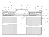
- FIG. 1 is a cross-sectional view of a battery that is an example of an electricity storage device according to an embodiment.
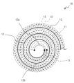
- FIG. 4 is a diagram illustrating a wound state of the electrode body.
- 5A and 5B are schematic diagrams showing the developed state of the positive electrode of the electrode assembly, in which FIG. 5A shows the state before the insulating tape is applied, and FIG. 5B shows the state after the insulating tape is applied.
- 13 is a longitudinal cross-sectional view showing a state in which a positive electrode tab is connected to an exposed portion of the positive electrode core material and is covered with insulating tape.
- Fig. 1 is a cross-sectional view of a battery 1, which is an example of an electricity storage device according to an embodiment.
- the battery 1 includes an electrode body 10 and an exterior can 20 that houses the electrode body 10.
- the exterior can 20 has a cylindrical portion 21, a bottom portion 22 that closes one end of the cylindrical portion, and an opening formed at the other end of the cylindrical portion, and the opening is closed with a sealing member 24.
- the exterior can 20 also houses an electrolyte together with the electrode body 10.
- the exterior can 20 has an annular groove 23 formed in the cylindrical portion 21, and the sealing member 24 is supported by the groove 23 to close the opening of the exterior can 20.
- the sealing member 24 side of the battery 1 will be referred to as the top, and the bottom 22 side of the exterior can 20 as the bottom.
- the battery 1 further includes a plurality of electrode tabs extending from various points of the electrode body 10 toward the sealing member 24 and directly connecting the first electrode constituting the electrode body 10 to the current collector 26 of the sealing member 24, and an upper insulating plate 34 arranged between the electrode body 10 and the sealing member 24.
- the electrode body 10 is a wound type electrode body in which the first electrode and the second electrode are wound with a separator interposed therebetween, and in this embodiment, the first electrode is a positive electrode and the second electrode is a negative electrode, and the electrode tab is a positive electrode tab 19.
- a plurality of positive electrode tabs 19 are arranged at predetermined intervals in the longitudinal direction of the positive electrode, and extend upward from the top of the positive electrode.
- the positive electrode tab 19 electrically connects the positive electrode to the sealing member 24.
- the negative electrode has a protruding portion electrically connected to the outer can 20 via the negative electrode current collector plate. Therefore, the sealing member 24 functions as the positive electrode terminal, and the outer can 20 functions as the negative electrode terminal.
- the upper insulating plate 34 prevents the positive electrode and the positive electrode tab 19 from touching the outer can 20, and also prevents the positive electrode tab 19 from touching the negative electrode of the electrode body 10.
- the electrode body 10 includes a positive electrode 11, a negative electrode 12, and a separator 13, all of which are strip-shaped long bodies that are wound in a spiral shape and alternately stacked in the radial direction of the electrode body 10.
- the negative electrode 12 has a composite layer, and the composite layer of the negative electrode 12 is formed with dimensions one size larger than the composite layer of the positive electrode 11 to prevent lithium precipitation. That is, the composite layer of the negative electrode 12 is formed longer in the longitudinal direction and width direction (short direction) than the composite layer of the positive electrode 11. In the example of FIG.
- the inner starting end of the positive electrode 11 is located outside the starting end of the negative electrode 12, and only the negative electrode 12 and the separator 13 are wound in the center of the electrode body 10.
- the separator 13 is formed with dimensions at least one size larger than the positive electrode 11, and two sheets are arranged to sandwich the positive electrode 11. As a result, when wound, the separator 13 is interposed between the positive electrode 11 and the negative electrode 12.
- the positive electrode 11 has a strip-shaped positive electrode core material and a positive electrode composite layer formed on at least one surface of the core material.
- the positive electrode core material can be a foil of a metal that is stable in the potential range of the positive electrode, such as aluminum or an aluminum alloy, or a film with the metal disposed on the surface.
- the positive electrode composite layer contains a positive electrode active material, a conductive agent such as acetylene black, and a binder such as polyvinylidene fluoride, and is preferably formed on both sides of the positive electrode core material.
- a lithium transition metal composite oxide is used as the positive electrode active material.
- the positive electrode tab 19 is connected to the positive electrode, but is preferably directly joined to the positive electrode core material by welding or the like.
- the negative electrode 12 has a strip-shaped negative electrode core material and a negative electrode composite layer formed on at least one surface of the core material.
- the negative electrode core material can be a foil of a metal that is stable in the potential range of the negative electrode, such as copper or a copper alloy, or a film with the metal disposed on the surface.
- the negative electrode composite layer contains a negative electrode active material and a binder such as styrene-butadiene rubber (SBR), and is preferably formed on both sides of the negative electrode core material.
- SBR styrene-butadiene rubber
- graphite or a silicon-containing compound is used as the negative electrode active material.
- a tongue-shaped negative electrode tab may be directly joined to the negative electrode core material by welding or the like, and then joined to the current collector plate.
- the non-aqueous electrolyte contained in the exterior can 20 includes a non-aqueous solvent and an electrolyte salt dissolved in the non-aqueous solvent.
- a non-aqueous solvent for example, esters, ethers, nitriles, amides, and mixed solvents of two or more of these are used as the non-aqueous solvent.
- the non-aqueous solvent may contain a halogen-substituted product in which at least a part of the hydrogen of these solvents is replaced with a halogen atom such as fluorine.
- the non-aqueous solvent include ethylene carbonate (EC), ethyl methyl carbonate (EMC), dimethyl carbonate (DMC), and mixed solvents of these.
- a lithium salt such as LiPF6 is used as the electrolyte salt.
- the outer can 20 is a cylindrical metal container with a bottom and an open axial end (top end), and has a cylindrical tube portion 21 and a circular bottom portion 22 when viewed from the bottom.
- the outer can 20 is generally made of a metal whose main component is iron, but may be made of a metal whose main component is aluminum, etc., especially when the outer can 20 is electrically connected to the positive electrode.
- the outer can 20 also has a groove portion 23 formed along the circumferential direction of the tube portion 21.
- the groove portion 23 is formed in the vicinity of the opening of the outer can 20, at a position a predetermined length away from the opening edge (the top end of the outer can 20).
- the predetermined length is, for example, a length equivalent to 1 to 20% of the axial length of the outer can 20.
- the bottom 22 of the exterior can 20 is provided with a safety valve mechanism that operates when an abnormality occurs in the battery 1.
- the sealing member 24 is not provided with a safety valve mechanism.
- the bottom 22 has, for example, a thin-walled portion. When an abnormality occurs in the battery 1 and the internal pressure rises, this thin-walled portion breaks preferentially, and a gas exhaust port is formed in the bottom 22.
- the groove portion 23 is a portion of the tubular portion 21 that protrudes inwardly from the exterior can 20, and is formed, for example, by spinning the tubular portion 21 from the outside. At the position where the groove portion 23 is formed, the exterior can 20 is reduced in diameter, and a thin groove is formed on the outer circumferential surface of the tubular portion 21.
- the groove portion 23 preferably has a substantially U-shaped cross section and is formed in a ring shape over the entire circumferential length of the tubular portion 21.
- the groove portion 23 is formed by processing the tubular portion 21 after the electrode body 10 is placed inside the exterior can 20.
- the inner diameter of the outer can 20 at the position where the groove 23 is formed is, for example, 80 to 99% of the maximum inner diameter of the outer can 20.
- An example of the length of the groove 23 along the radial direction of the outer can 20 is 0.5 to 2.0 mm. Since the diameter of the electrode body 10 is approximately the same as the maximum inner diameter of the outer can 20, the electrode body 10 and the groove 23 overlap in the vertical direction of the battery 1.
- the lower end of the positive electrode tab 19 is connected to the upper end of the positive electrode at multiple points, and the other end is connected to the cap 25 via the current collector plate 26.
- the sealing member 24 has a cap 25, a current collecting plate 26, and a gasket 33, and is formed into a disk shape as a whole.
- the sealing member 24 is placed on the groove 23 of the outer can 20 and is fixed to the opening of the outer can 20.
- the upper end of the opening is bent inward and crimped to the sealing member 24 via the gasket 33.
- the sealing member 24 is fixed to the upper end of the outer can 20 by the groove 23 of the outer can 20 and the crimping portion, and closes the opening of the outer can 20.
- the crimping portion is formed in a ring shape along the circumferential direction of the outer can 20, and holds the sealing member 24 together with the groove 23.
- the sealing member 24 includes a member for covering the upper opening of the outer can 20, such as an upper insulating plate 34.
- the cap 25 is a disk-shaped metal member that is exposed to the outside of the exterior can 20 and forms the top surface of the battery 1.
- the cap 25 has a shape (raised portion) in which the radial center part protrudes outward from the battery 1.
- Wiring material is connected to the cap 25 when the batteries 1 are modularized to form a battery pack. For this reason, the cap 25 functions as an external terminal of the battery 1, and is also called an external terminal or top cover.
- the positive electrode tab 19 is connected to the current collector 26, and the cap 25 functions as a positive electrode external terminal.
- the current collector 26 is a metal member having a diameter similar to that of the cap 25, and is disposed closer to the electrode body 10 than the cap 25.
- the current collector 26 has an opening 26a in the radial center and is formed in a ring shape.
- the cap 25 and the current collector 26 are welded together, and the current collector 26 is welded, for example, to a position closer to the outer periphery of the cap 25 than to the radial center.
- the current collector 26 has a ring-shaped protrusion 26b, which will be described later, and the protrusion 26b forms the welded portion with the cap 25.
- the positive electrode tab 19 connected to the positive electrode of the electrode body 10 is connected to the current collector 26, so that the current collector 26 functions as a positive electrode current collector.
- the gasket 33 is provided on the outer periphery of the laminate of the cap 25 and the current collector plate 26.
- the gasket 33 is an annular resin or rubber member that prevents contact between the cap 25 and the current collector plate 26 and the outer can 20, and ensures insulation between the outer can 20 and the sealing member 24.
- the gasket 33 covers the upper surface of the cap 25, the sides of the cap 25 and the current collector plate 26, and the lower surface of the current collector plate 26 on the outer periphery of the laminate.
- the gasket 33 also seals the inside of the battery 1 by filling the gap between the outer can 20 and the sealing member 24.
- the gasket 33 is formed to cover most of the lower surface of the current collector 26, and is interposed between the current collector 26 and the upper insulating plate 34.
- An opening 33a is formed in the radial center of the gasket 33, which overlaps with the opening 26a of the current collector 26 in the vertical direction.
- the gasket 33 may have a through hole 33b formed in a portion located below the current collector 26. It is expected that electrolyte will accumulate on the upper surface of the gasket 33, and by providing the through hole 33b, such electrolyte can be efficiently returned to the electrode body 10 side.
- multiple through holes 33b are formed along the circumferential direction of the gasket 33.
- the gasket 33 has an inward extension portion 33c that extends inward from the outer periphery of the cap 25.
- the upper end of the exterior can 20 may be bent inward to form a bent portion 210 and used as a negative electrode external terminal.
- FIG. 3 is a schematic diagram showing the developed state of the positive electrode 11 of the electrode body 10, where (a) shows the state before the insulating tape is applied, and (b) shows the state after the insulating tape is applied.
- the positive electrode 11 has a positive electrode tab 19 connected to one end (upper side).
- the positive electrode 11 includes a positive electrode core material 11-1 and a positive electrode composite layer 11-2 formed on its surface.
- the positive electrode tab 19 is directly connected to the positive electrode core material 11-1. Therefore, a positive electrode core material exposed portion 11a without a positive electrode composite layer 11-2 is formed on the upper side of the positive electrode 11, and the base of the positive electrode tab 19 is welded to this portion.
- the positive electrode tab 19 extends above the electrode body 10 and is connected to the current collector plate 26 as shown in FIG. 1.
- the positive electrode composite layer 11-2 is formed on both sides of the positive electrode core material 11-1, and the positive electrode core material exposed portion 11a is also formed on both sides.
- the positive electrode tab 19 is usually connected to one side.
- the positive electrode composite layer 11-2 is formed on the positive electrode core material 11-1 by intermittent spot coating (SKC). That is, by stopping the coating of the positive electrode composite layer 11-2 for a predetermined period of time, the positive electrode core material exposed portion 11a is formed at predetermined intervals.
- the positive electrode composite layer 11-2 is formed by continuous coating.
- the positive electrode mixture layer 11-2 contains a positive electrode active material, a conductive agent such as acetylene black, and a binder such as polyvinylidene fluoride, and has a predetermined thickness (for example, less than 1 mm).
- the positive electrode tab 19 is a metal foil such as aluminum, and its thickness is thinner than that of the positive electrode mixture layer 11-2.
- an insulating member such as an insulating tape 15 is attached to insulate the base of the positive electrode tab 19.
- a polyimide insulating tape is used as the insulating tape 15, but an insulating tape such as polypropylene may also be used.
- the insulating tape 15 is also usually thinner than the positive electrode mixture layer 11-2.
- the positive electrode tab 19 and the insulating tape 15 mitigate the reduction in thickness caused by the positive electrode core material exposed portion 11a.
- the average thickness of the ⁇ layer taking into account the thickness reduction due to the presence of the positive electrode core exposed portion 11a and the thickness increase due to the presence of the positive electrode tab 19 and the insulating tape 15, is somewhat smaller than the average thickness of the ⁇ layer.
- the stress during expansion is relatively small in the upper part of the electrode body 10 (laminated part of the ⁇ layer) where the exposed part of the positive electrode core material 11a is present, while the stress is large in the central and lower parts (laminated part of the ⁇ layer) where the exposed part of the positive electrode core material 11a is not present, and the generated stress becomes non-uniform.
- the shear force and the radial force received from the outer periphery can 20 become large.
- the positive electrode 11 is likely to float at the top of the electrode body 10 (the laminated portion of the ⁇ layer) on the inner circumference side.
- buckling may occur on the outer circumference side other than the top of the electrode body 10 (the laminated portion of the ⁇ layer).
- a thin protective tape is placed on the outer periphery of the positive electrode 11 having an exposed portion 11a of the positive electrode core material, and a thick protective tape is placed on the inner periphery, improving the inter-electrode gap that occurs on the inner periphery after winding and suppressing the occurrence of buckling on the outer periphery.
- different insulating tapes are used for the outer peripheral side insulating tape 15-1 corresponding to the first insulating member and the inner peripheral side insulating tape (second insulator) 15-2 corresponding to the second insulating member. That is, a relatively thick insulating tape is used for the inner peripheral side insulating tape 15-2, and a relatively thin insulating tape is used for the outer peripheral side insulating tape 15-1. This prevents the positive electrode 11 from floating on the inner peripheral side (creation of gaps between the electrode plates) and the positive electrode from buckling on the outer peripheral side.
- two different thicknesses of insulating tape 15 are used, but this is not limited to this, and an intermediate thickness may be used in the middle section.
- Figure 4 is a longitudinal cross-sectional view showing the positive electrode tab 19 connected to the exposed portion 11a of the positive electrode core material and covered with insulating tape 15.
- the positive electrode composite layer 11-2 is not formed, and thus the positive electrode core exposed portion 11a is formed.
- the base of the positive electrode tab 19 is then welded to the positive electrode core 11-1 in the center of this positive electrode core exposed portion 11a.
- an insulating tape 15 is provided to cover the end of the positive electrode composite layer 11-2 on the positive electrode core exposed portion 11a side, as well as to cover the positive electrode tab 19 and the remaining positive electrode core exposed portion 11a.
- the spatial volume obtained by subtracting the volume of the positive electrode tab 19 and the volume of the insulating tape 15 from the total volume of the positive electrode core exposed portion 11a is the difference in volume with respect to the portion where the positive electrode core exposed portion 11a does not exist.
- the total volume of the positive electrode core exposed portion 11a is the volume if the positive electrode composite layer 11-2 were present here, and is the value obtained by multiplying the area of the positive electrode core exposed portion by the thickness of the positive electrode composite layer 11-2.
- the differential spatial volume can be reduced.
- the thickness of the insulating tape 15-2 on the inner circumferential side is preferably 30% or less of the thickness of the positive electrode mixture layer 12-2. Since the insulating tape 15-2 also covers the positive electrode tab 19, if the insulating tape 15-2 is too thick, the thickness of that portion will increase.
- the length of the positive electrode core exposed portion 11a in the longitudinal direction is preferably 30 mm or more, since the positive electrode tab 19 needs to be connected to the positive electrode core 11-1 over a certain area in order to reduce its electrical resistance, and the above length is preferable in consideration of the ease of the connection work.
- the inner insulating tape 15-2 when wound up, is made thicker and the outer insulating tape 15-1 is made relatively thin. This eliminates uneven stresses that occur when the electrode body 10 expands and contracts, and suppresses the occurrence of gaps and buckling.
- Table 1 shows the results of investigating the occurrence of lifting and buckling in the electrode body 10 when the thickness of the insulating tape 15 and the longitudinal length (spot length) of the positive electrode core material exposed portion 11a are changed.
- mm 3 is written as "mm3" for convenience.
- Increasing the thickness of the insulating tape 15 reduces the spatial volume and increases the surface pressure. Also, observations using a SIM (scanning ion microscope) showed that no inner gaps occur if the average spatial volume of the four inner exposed positive electrode core material portions 11a (tabs 1 to 4 (Tab1-Tab4)) is 17.4 mm3 or less.
- the spatial volume of one positive electrode core exposed portion 11a was fixed at 17.4 mm3, and the tape thickness and spot length were changed to obtain the conditions for an appropriate tape thickness. It was found that if the spot length was 30 mm or less, the tape thickness should be 0.040 mm or less.
- Table 3 shows the experimental results when there was a difference in tape thickness between the inner and outer circumferential tabs.
- Comparative Example 1 (0.175 mm on the inner circumference side, 0.175 mm on the outer circumference side), gaps occur.
- Comparative Example 2 (0.03 mm on the inner circumference side, 0.03 mm on the outer circumference side), both gaps occur and foil breaks occur.
- Comparative Example 3 (0.05 mm on the inner circumference side, 0.05 mm on the outer circumference side), only foil breaks occur.
- Example 4 (0.03 mm on the inner circumference side, 0.175 mm on the outer circumference side), a gap is generated, so it is marked as NG in Table 3, but in reality the gap has been improved, and it was found that 0.03 mm is the limit value.
- Example 5 (0.05 mm on the inner circumference side, 0.175 mm on the outer circumference side), both gaps and foil breaks were eliminated. Also, as shown in Example 7, even if the spot length is increased to 60-70 mm, gaps can be prevented by making the tape thickness on the inner circumference side 0.06 mm.
- the thickness of the positive electrode composite layer is 0.07 mm
- the thickness of the core material is 0.015 mm
- the thickness of the positive electrode tab is 0.070 mm.
- the thickness of the insulating tape 15 on the inner circumference side is increased, and the insulating tape 15 on the outer circumference side is made relatively thin. This prevents gaps from occurring between the plates on the inner circumference side of the electrode body 10, and prevents the foil from breaking on the outer circumference side.
- the thickness of the inner insulating tape 15 should be 0.03 mm or more, preferably 0.04 mm or more, and more preferably 0.05 mm.
Landscapes
- Chemical & Material Sciences (AREA)
- Chemical Kinetics & Catalysis (AREA)
- Electrochemistry (AREA)
- General Chemical & Material Sciences (AREA)
- Engineering & Computer Science (AREA)
- Manufacturing & Machinery (AREA)
- Connection Of Batteries Or Terminals (AREA)
- Secondary Cells (AREA)
Priority Applications (3)
| Application Number | Priority Date | Filing Date | Title |
|---|---|---|---|
| JP2025503717A JPWO2024181071A1 (https=) | 2023-02-28 | 2024-02-07 | |
| EP24763555.0A EP4675726A1 (en) | 2023-02-28 | 2024-02-07 | Secondary battery |
| CN202480013861.5A CN120731521A (zh) | 2023-02-28 | 2024-02-07 | 二次电池 |
Applications Claiming Priority (2)
| Application Number | Priority Date | Filing Date | Title |
|---|---|---|---|
| JP2023030486 | 2023-02-28 | ||
| JP2023-030486 | 2023-02-28 |
Publications (1)
| Publication Number | Publication Date |
|---|---|
| WO2024181071A1 true WO2024181071A1 (ja) | 2024-09-06 |
Family
ID=92589643
Family Applications (1)
| Application Number | Title | Priority Date | Filing Date |
|---|---|---|---|
| PCT/JP2024/004137 Ceased WO2024181071A1 (ja) | 2023-02-28 | 2024-02-07 | 二次電池 |
Country Status (5)
| Country | Link |
|---|---|
| EP (1) | EP4675726A1 (https=) |
| JP (1) | JPWO2024181071A1 (https=) |
| CN (1) | CN120731521A (https=) |
| TW (1) | TW202447998A (https=) |
| WO (1) | WO2024181071A1 (https=) |
Cited By (1)
| Publication number | Priority date | Publication date | Assignee | Title |
|---|---|---|---|---|
| WO2025094774A1 (ja) * | 2023-10-30 | 2025-05-08 | パナソニックIpマネジメント株式会社 | 非水電解質二次電池 |
Citations (4)
| Publication number | Priority date | Publication date | Assignee | Title |
|---|---|---|---|---|
| JP2004296159A (ja) | 2003-03-26 | 2004-10-21 | Japan Storage Battery Co Ltd | 円筒形蓄電池 |
| JP2021531618A (ja) * | 2018-07-20 | 2021-11-18 | エルジー・ケム・リミテッド | 電極組立体及びこれを含む二次電池 |
| WO2022249989A1 (ja) * | 2021-05-25 | 2022-12-01 | 三洋電機株式会社 | 非水電解質二次電池 |
| WO2023281973A1 (ja) * | 2021-07-05 | 2023-01-12 | 三洋電機株式会社 | 円筒形電池 |
-
2024
- 2024-02-07 EP EP24763555.0A patent/EP4675726A1/en active Pending
- 2024-02-07 CN CN202480013861.5A patent/CN120731521A/zh active Pending
- 2024-02-07 WO PCT/JP2024/004137 patent/WO2024181071A1/ja not_active Ceased
- 2024-02-07 JP JP2025503717A patent/JPWO2024181071A1/ja active Pending
- 2024-02-20 TW TW113105928A patent/TW202447998A/zh unknown
Patent Citations (4)
| Publication number | Priority date | Publication date | Assignee | Title |
|---|---|---|---|---|
| JP2004296159A (ja) | 2003-03-26 | 2004-10-21 | Japan Storage Battery Co Ltd | 円筒形蓄電池 |
| JP2021531618A (ja) * | 2018-07-20 | 2021-11-18 | エルジー・ケム・リミテッド | 電極組立体及びこれを含む二次電池 |
| WO2022249989A1 (ja) * | 2021-05-25 | 2022-12-01 | 三洋電機株式会社 | 非水電解質二次電池 |
| WO2023281973A1 (ja) * | 2021-07-05 | 2023-01-12 | 三洋電機株式会社 | 円筒形電池 |
Non-Patent Citations (1)
| Title |
|---|
| See also references of EP4675726A1 |
Cited By (1)
| Publication number | Priority date | Publication date | Assignee | Title |
|---|---|---|---|---|
| WO2025094774A1 (ja) * | 2023-10-30 | 2025-05-08 | パナソニックIpマネジメント株式会社 | 非水電解質二次電池 |
Also Published As
| Publication number | Publication date |
|---|---|
| CN120731521A (zh) | 2025-09-30 |
| JPWO2024181071A1 (https=) | 2024-09-06 |
| EP4675726A1 (en) | 2026-01-07 |
| TW202447998A (zh) | 2024-12-01 |
Similar Documents
| Publication | Publication Date | Title |
|---|---|---|
| EP2136429B1 (en) | Electrode assembly and lithium secondary battery with same | |
| WO2018079291A1 (ja) | 非水電解質二次電池用電極及び非水電解質二次電池 | |
| WO2023176730A1 (ja) | 二次電池用電極 | |
| JP7669293B2 (ja) | 密閉電池 | |
| JP6953422B2 (ja) | 非水電解質二次電池用電極及び非水電解質二次電池 | |
| WO2024181071A1 (ja) | 二次電池 | |
| EP4459783A1 (en) | Current collector plate and power storage device | |
| WO2024181065A1 (ja) | 二次電池 | |
| EP4675722A1 (en) | Cylindrical battery | |
| JP7854994B2 (ja) | 密閉電池 | |
| EP4700875A1 (en) | Battery | |
| WO2024247781A1 (ja) | 円筒形電池 | |
| WO2025047154A1 (ja) | 円筒形電池 | |
| WO2026094755A1 (ja) | 円筒形電池 | |
| WO2024247779A1 (ja) | 円筒形電池 | |
| WO2024181038A1 (ja) | 円筒形電池 | |
| WO2024048246A1 (ja) | 蓄電装置 | |
| WO2024262490A1 (ja) | 円筒形電池及びその製造方法 | |
| WO2026094792A1 (ja) | 円筒形電池 | |
| WO2024224957A1 (ja) | 円筒形電池及びその製造方法 | |
| WO2024181468A1 (ja) | 蓄電装置 | |
| CN120814085A (zh) | 圆筒形电池 | |
| WO2024181423A1 (ja) | 蓄電装置 | |
| WO2025183002A1 (ja) | 非水電解質二次電池 | |
| KR20250111639A (ko) | 전극 조립체 및 이를 구비한 이차 전지 |
Legal Events
| Date | Code | Title | Description |
|---|---|---|---|
| 121 | Ep: the epo has been informed by wipo that ep was designated in this application |
Ref document number: 24763555 Country of ref document: EP Kind code of ref document: A1 |
|
| ENP | Entry into the national phase |
Ref document number: 2025503717 Country of ref document: JP Kind code of ref document: A |
|
| WWE | Wipo information: entry into national phase |
Ref document number: 2025503717 Country of ref document: JP |
|
| WWE | Wipo information: entry into national phase |
Ref document number: 202517078721 Country of ref document: IN |
|
| WWE | Wipo information: entry into national phase |
Ref document number: 202480013861.5 Country of ref document: CN |
|
| WWE | Wipo information: entry into national phase |
Ref document number: 2024763555 Country of ref document: EP |
|
| NENP | Non-entry into the national phase |
Ref country code: DE |
|
| WWP | Wipo information: published in national office |
Ref document number: 202480013861.5 Country of ref document: CN |
|
| ENP | Entry into the national phase |
Ref document number: 2024763555 Country of ref document: EP Effective date: 20250929 |
|
| ENP | Entry into the national phase |
Ref document number: 2024763555 Country of ref document: EP Effective date: 20250929 |
|
| ENP | Entry into the national phase |
Ref document number: 2024763555 Country of ref document: EP Effective date: 20250929 |
|
| WWP | Wipo information: published in national office |
Ref document number: 202517078721 Country of ref document: IN |
|
| WWP | Wipo information: published in national office |
Ref document number: 2024763555 Country of ref document: EP |