WO2024180831A1 - ホルダ、切削工具及び切削加工物の製造方法 - Google Patents
ホルダ、切削工具及び切削加工物の製造方法 Download PDFInfo
- Publication number
- WO2024180831A1 WO2024180831A1 PCT/JP2023/042134 JP2023042134W WO2024180831A1 WO 2024180831 A1 WO2024180831 A1 WO 2024180831A1 JP 2023042134 W JP2023042134 W JP 2023042134W WO 2024180831 A1 WO2024180831 A1 WO 2024180831A1
- Authority
- WO
- WIPO (PCT)
- Prior art keywords
- central axis
- holder
- hole
- axis
- protrusion
- Prior art date
- Legal status (The legal status is an assumption and is not a legal conclusion. Google has not performed a legal analysis and makes no representation as to the accuracy of the status listed.)
- Ceased
Links
Images


Classifications
-
- B—PERFORMING OPERATIONS; TRANSPORTING
- B23—MACHINE TOOLS; METAL-WORKING NOT OTHERWISE PROVIDED FOR
- B23B—TURNING; BORING
- B23B29/00—Holders for non-rotary cutting tools; Boring bars or boring heads; Accessories for tool holders
-
- B—PERFORMING OPERATIONS; TRANSPORTING
- B23—MACHINE TOOLS; METAL-WORKING NOT OTHERWISE PROVIDED FOR
- B23B—TURNING; BORING
- B23B29/00—Holders for non-rotary cutting tools; Boring bars or boring heads; Accessories for tool holders
- B23B29/03—Boring heads
Definitions
- This disclosure relates to a method for manufacturing a holder, a cutting tool, and a machined product, and more specifically, to a method for manufacturing a holder having two members, a cutting tool, and a machined product.
- Patent Document 1 holders described in JP-T-2001-502252 (Patent Document 1) and JP-T-2016-516600 (Patent Document 2) are known.
- the holders in the cutting tools described in these patent documents consist of two members, a first component and a second component.
- a holder has a rod shape extending from a first end to a second end along a central axis, and includes a first member located on the side of the first end, a second member located closer to the second end than the first member, and a fastener for fixing the first member to the second member.
- the first member has a first end face located on the side of the second end, a first outer peripheral surface extending from the first end face toward the first end, a protrusion extending from the first end face toward the second end and having a first surface facing the second end, and a first hole extending from the first surface toward the first end.
- the second member has a second end face located on the side of the first end and facing the first end face, a second outer peripheral surface extending from the second end face toward the second end, and a second hole extending from the second outer peripheral surface toward the first hole.
- the fastener is inserted into the first hole through the second hole, and the protrusion is located on the central axis.
- FIG. 2 is a top view showing a holder according to an embodiment.
- 2 is a perspective view of the holder shown in FIG. 1 as viewed from the A1 direction.
- FIG. 3 is a perspective view of a state in which a first member and a second member shown in FIG. 2 are disassembled.
- 4 is a perspective view of the first member, the second member, etc. shown in FIG. 3 as viewed from a direction A2.
- 2 is a plan view of the holder shown in FIG. 1 as seen through from above;
- FIG. 6 is an enlarged view of a region B1 shown in FIG. 5 .
- FIG. 6 is a plan view of the first member shown in FIG. 5 .
- FIG. 4 is a plan view of the first member as viewed from the second end side.
- FIG. 1 is a perspective view of the holder shown in FIG. 1 as viewed from the A1 direction.
- FIG. 3 is a perspective view of a state in which a first member and
- FIG. 4 is a plan view of the second member as viewed from the first end side.
- 2 is a plan view of the holder shown in FIG. 1 as viewed from a direction A3.
- 4 is a plan view of the first member shown in FIG. 3 as viewed from the A4 direction.
- FIG. 2 is a schematic explanatory diagram showing one step of a method for producing a machined product according to one embodiment.
- FIG. 2 is a schematic explanatory diagram showing one step of a method for producing a machined product according to one embodiment.
- FIG. 2 is a schematic explanatory diagram showing one step of a method for producing a machined product according to one embodiment.
- the holder 1 of the present disclosure is rod-shaped and extends from a first end 1a to a second end 1b along a central axis O1.
- the central axis O1 is an axis that passes through the center of the holder 1.
- the first end 1a will be referred to as the front end 1a and the second end 1b as the rear end 1b.
- the holder 1 has a first member 3 located on the tip 1a side, a second member 5 located closer to the rear end 1b than the first member 3, and a fixture 7 that fixes the first member 3 to the second member 5.
- the first member 3 is called a head or the like, and is a portion to which a cutting insert is attached.
- the second member 5 is called a shank or the like, and is a portion that is gripped by a machine tool.
- the first member 3 includes the tip 1a
- the second member 5 includes the rear end 1b.
- Fig. 1 is a plan view of the holder 1 from above
- Fig. 2 is a perspective view of the holder 1 as viewed from the A1 direction shown in Fig. 1
- Fig. 3 is a perspective view showing the first member 3 shown in Fig. 2 separated from the second member 5, showing the first member 3, second member 5 and fixing device 7 disassembled
- Fig. 4 is a perspective view of the holder 1 shown in Fig. 3 as viewed from the A2 direction.
- the first member 3 has a first tip surface 9 located on the tip end 1a side, a first rear end surface 11 (first end surface) located on the rear end 1b side, and a first outer peripheral surface 13 located between the first tip surface 9 and the first rear end surface 11.
- the first outer peripheral surface 13 extends from the first rear end surface 11 toward the tip 1a.
- the first outer peripheral surface 13 has a first upper surface 15 (upper surface), a first lower surface 17 (lower surface) located opposite the first upper surface 15, a first front surface 19 located between the first upper surface 15 and the first lower surface 17, and a first back surface 21 located opposite the first front surface 19.
- the first tip surface 9, the first rear end surface 11, the first upper surface 15, the first lower surface 17, the first front surface 19, and the first back surface 21 may each have a flat shape.
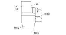
- the first member 3 has a pocket 23 located on the side of the tip 1a and opening at the first tip surface 9, the first upper surface 15, and the first front surface 19, and a protrusion 25 extending from the first rear end surface 11 toward the rear end 1b.
- the protrusion 25 may be cylindrical or conical extending along the central axis O1.
- the cylindrical shape does not have to be strictly cylindrical (conical), and may have a hole, as in the non-limiting example shown in FIG. 4.
- the pocket 23 is a portion where the cutting insert is attached.
- the cutting insert may be fixed to the pocket 23 by a fixing member such as a fixing screw or a clamp.
- a fixing member such as a fixing screw or a clamp.
- the first front surface 19 may be replaced with a side surface in order to identify the position of the pocket 23 in the first member 3.
- the protrusion 25 has a first surface 27 facing the rear end 1b. Facing the rear end 1b does not mean that the first surface 27 is substantially perpendicular to the central axis O1, but if the first surface 27 is substantially perpendicular to the central axis O1, the holder 1 has high holding stability. "Substantially perpendicular” means that the angle between the first surface 27 and the central axis O1 is within the range of ⁇ 5°.
- the protrusion 25 has a first opening 29 located on the first surface 27.
- the first member 3 may have a first hole 31 extending from the first opening 29 toward the tip 1a.
- the first member 3 may have a first hole 31 extending from the first surface 27 toward the tip 1a, and the first hole 31 may have a first opening 29 located on the first surface 27.
- the first member 3 has the entire first hole 31.
- the first hole 31 may approach either surface of the first outer peripheral surface 13 as it moves toward the tip 1a.
- the first hole 31 approaches the first front surface 19 as it moves toward the tip 1a.
- Figure 5 is a plan view seen through the top of the holder 1 shown in Figure 1
- Figure 6 is an enlarged view corresponding to region B1 shown in Figure 5
- Figure 7 is a plan view of the first member 3 shown in Figure 5.
- the second member 5 has a second tip surface 33 (second end surface) located on the tip 1a side and facing the first rear end surface 11, a second rear end surface 35 located on the opposite side to the second tip surface 33, and a second outer peripheral surface 37 located between the second tip surface 33 and the second rear end surface 35.
- the second outer peripheral surface 37 extends from the second tip surface 33 toward the rear end 1b.
- the second outer peripheral surface 37 has a second upper surface 39, a second lower surface 41 located opposite the second upper surface 39, a second front surface 43 located between the second upper surface 39 and the second lower surface 41, and a second rear surface 45 (rear surface) located opposite the second front surface 43.
- the second tip surface 33, the second rear end surface 35, the second upper surface 39, the second lower surface 41, the second front surface 43, and the second rear surface 45 may each be flat.
- the second front surface 43 may face the same side as the first front surface 19.
- the second rear surface 45 may face the opposite side to the second front surface 43.
- the directions in which the first upper surface 15, the first lower surface 17, the first front surface 19, and the first rear surface 21 face are the same as the directions in which the second upper surface 39, the second lower surface 41, the second front surface 43, and the second rear surface 45 face, respectively.
- the first upper surface 15 is connected to the second upper surface 39
- the first lower surface 17 is connected to the second lower surface 41
- the first front surface 19 is connected to the second front surface 43
- the first rear surface 21 is connected to the second rear surface 45.
- the direction in which the second upper surface 39 faces will be referred to as the upper side, the direction in which the second lower surface 41 faces as the lower side, the direction in which the second front surface 43 faces as the foreside, and the direction in which the second back surface 45 faces as the backside.
- the second outer surface 37 has a second opening 47 (opening).
- the second opening 47 is located on the second back surface 45.
- the second member 5 also has a second hole 49 extending from the second opening 47 toward the tip 1a.
- the second member 5 may have a second hole 49 extending from the second outer surface 37 toward the tip 1a, and the second hole 49 may have a second opening 47 located on the second outer surface 37.
- the second hole 49 may extend from the second outer surface 37 toward the first hole 31.
- the second opening 47 may be used to insert the fastener 7.
- the second member 5 has the entire second hole 49.
- the second hole 49 may approach either surface of the second outer peripheral surface 37 as it moves toward the tip 1a.
- the second hole 49 moves toward the second front surface 43 as it moves toward the tip 1a.
- the portion into which the fastener 7 is inserted examples include the first hole 31 and the second hole 49, but the portion into which the fastener 7 is inserted is not limited to these. In addition to the first hole 31 and the second hole 49, the portion into which the fastener 7 is inserted may also have a portion that connects these holes.
- the second member 5 has a recess 50 located closer to the tip 1a than the second hole 49.
- the protrusion 25 is inserted into the recess 50.
- the inner diameter of the recess 50 may be larger than the inner diameter of the second hole 49.
- the recess 50 may be connected to the second hole 49 on the rear end 1b side.
- the end of the second hole 49 on the side of the tip 1a is located at the end of the recess 50 on the side of the rear end 1b. More specifically, the recess 50 has a second surface 51 located on the side of the rear end 1b, and the second hole 49 has a third opening 53 located at the end on the side of the tip 1a. The third opening 53 is located on the second surface 51 of the recess 50.
- the second surface 51 may face the first surface 27.
- the inner diameter of the recess 50 may be slightly larger than the outer diameter of the protrusion 25, i.e., a slight "play" may be provided between the recess 50 and the protrusion 25.
- the fastener 7 is inserted into the first hole 31 through the second hole 49.
- the fastener 7 and the first hole 31 are provided with threaded grooves, and by tightening the fastener 7 inserted into the first hole 31, the second member 5 moves relatively closer to the first member 3, and the first member 3 is fixed to the second member 5.
- the portion where the threads are provided may be located closer to the tip 1a than the portion where the threads are not provided.
- the inner diameter of the portion where the threads are provided may be smaller than the inner diameter of the portion where the threads are not provided.
- the second hole 49 does not need to have a thread groove.
- the inner diameter of the second hole 49 may be slightly larger than the outer diameter of the fastener 7, i.e., a slight "play" may be provided between the second hole 49 and the fastener 7. In such a case, the second hole 49 is less likely to be an obstacle when the fastener 7 is inserted into the first hole 31, and the fastener 7 can be easily inserted into the first hole 31.
- the protrusion 25 is located on the central axis O1.
- the central axis O1 passes through the protrusion 25.
- the central axis O1 passes through the center P1 of the first rear end face 11, and the center P1 of the first rear end face 11 is located at the protrusion 25.
- the center P1 of the first rear end face 11 is located on the first surface 27.
- FIG. 8 is a plan view of the first member 3 as viewed from the rear end 1b side
- FIG. 9 is a plan view of the second member 5 as viewed from the tip 1a side.
- the second member 5 in the non-limiting example shown in FIG. 1 etc. has a rectangular prism shape.
- the central axis of the second member 5 may be regarded as the central axis O1 of the holder 1.
- the central axis of the second member 5 passing through the center P2 of the second rear end face 35 and extending in a direction parallel to the second outer peripheral surface 37 may be regarded as the central axis O1 of the holder 1.
- an opening for inserting the fixing device 7 may be provided on the side of the shank from the viewpoint of ease of insertion of the fixing device 7.
- a protrusion 25 is provided only on the top surface side of the head, the hole in the center of the head is located closer to the tip 1a, which tends to reduce the rigidity of the head.
- the central axis O1 passes through the protrusion 25, i.e., the protrusion 25 is located at the center P1 of the first rear end face 11, so the rigidity of the first member 3 is increased, and in addition, the cutting load applied to the first member 3 can be stably received by the second member 5. Therefore, the holder 1 has high holding stability and high joining stability. Furthermore, when the first surface 27 is located on the central axis O1, in other words, when the central axis O1 passes through the first surface 27, the rigidity of the first member 3 tends to be higher.
- the end of the first member 3 on the side of the rear end 1b may be located on the protrusion 25. More specifically, the end of the first member 3 on the side of the rear end 1b may be located on the first surface 27. In this case, it becomes easier to insert the first member 3 into the second member 5. In addition, the rigidity of the portion of the second member 5 that is joined to the first member 3 and is located on the side of the tip 1a is increased.
- the end of the second member 5 on the side of the tip 1a may be located on the second tip surface 33. In this case, it becomes easier to insert the first member 3 into the second member 5. In addition, the rigidity of the portion of the first member 3 on the side of the tip 1a that joins with the second member 5 is increased.
- the fixing device 7 may have a shaft portion 54 extending along the axis of the fixing device 7.
- the shaft portion 54 may have a thread groove on the side of the tip 1a.
- the first hole 31 is provided with a thread groove
- the second hole 49 is not provided with a thread groove, so it is sufficient that the portion of the shaft portion 54 that is inserted into the first hole 31 is provided with a thread groove.
- the outer diameter of the portion of the shaft portion 54 that has the thread groove may be smaller than the outer diameter of the portion of the shaft portion 54 that does not have the thread groove.
- the fixing device 7 may have a head 55 located closer to the rear end 1b than the shaft 54.
- the head 55 may have an outer diameter larger than the shaft 54.
- the head 55 may be configured to apply a force to the second member 5 in the direction of the tip 1a by abutting against a third surface 56 located between the small diameter portion 49a and the large diameter portion 49b.
- the small diameter portion 49a may be connected to the large diameter portion 49b, and the large diameter portion 49b may have the third surface 56.
- the head 55 may be separated from the first member 3. In such a case, the head 55 can apply force to the second member 5 in the direction of the tip 1a more efficiently.
- the second opening 47 may be located on the back surface. In the holder 1 shown in this embodiment, the second opening 47 is located on the second back surface 45. When the second member 5 is attached to a machine tool, the second back surface 45 generally faces the operator, so when the holder 1 has the above configuration, it becomes easier to insert the fixing device 7 into the second member 5.
- the protrusion 25 may be spaced apart from the side surface. In the holder 1 shown in this embodiment, the protrusion 25 is spaced apart from the first outer peripheral surface 13. In such a case, it becomes easier to insert the first member 3 into the second member 5 from the tip 1a side.
- the first hole 31 may be located closer to the tip 1a than the protrusion 25.
- the protrusion 25 is not longer than necessary, making it easier to insert the first member 3 into the second member 5.
- the fastener 7 may also be located closer to the rear end 1b than the first rear end face 11. In the holder 1 shown in this embodiment, the entire fastener 7 is located closer to the rear end 1b than the first rear end face 11.
- the first opening 29 may be located on the rear side of the central axis O1.
- the first hole 31 is more likely to be located on the rear side, and the first hole 31 is more likely to be located away from the pocket 23.
- the rigidity of the first member 3 is more likely to be high.
- the entire first opening 29 is located on the rear side of the central axis O1, i.e., on the side of the first rear surface 21.
- the center of the second opening 47 may be located on the lower side.
- the center of the second opening 47 is located on the side of the second lower surface 41.
- the first hole 31 communicating with the second hole 49 is also located on the lower side, so that the first hole 31 tends to be located away from the pocket 23.
- the rigidity of the first member 3 tends to be high.
- at least a part of the second opening 47 is located below the central axis O1.
- Figure 10 is a plan view of the holder 1 shown in Figure 1 as viewed from the A3 direction.
- the protrusion 25 When the first member 3 is viewed from the rear end 1b side, the protrusion 25 may be asymmetric with respect to the central axis O1. In other words, the protrusion 25 does not have to have n-fold symmetry (n is an integer equal to or greater than 2) around the central axis O1. For example, when the first member 3 is viewed from the rear end 1b side, the center of the protrusion 25 may be away from the central axis O1.
- being asymmetric means, for example, that the first surface 27 is an ellipse, or a polygon with rounded vertices. In such a case, when attaching the first member 3, for example, mistakes such as attaching the first member 3 upside down are less likely to occur.
- the fixing device 7 may have a bottom portion 57 located on the side of the tip end 1a.
- the fixing device 7 may also have a head end portion 58 located on the side of the rear end 1b.
- the bottom portion 57 and the head end portion 58 may be ends in a direction along the central axis O2 of the fixing device 7.
- the center P3 of the bottom portion 57 and the center P4 of the head end portion 58 may pass through the central axis O2 of the fixing device 7.
- the imaginary line segment connecting the center P3 of the bottom 57 and the center P4 of the head end 58 is defined as the axis S of the fixture 7.
- the length L1 of the axis S in the direction along the central axis O1 may be longer than the length L2 of the axis S in the direction perpendicular to the central axis O1.
- the first member 3 is more easily moved toward the rear end 1b, or the second member 5 is more easily moved toward the tip 1a.
- the case where the axis S is viewed from a direction perpendicular to both the axis S and the central axis O1 may be the case where the axis S is viewed from a direction perpendicular to the second upper surface 39.
- the axis S may be located closer to the lower surface (first lower surface 17) than the central axis O1.
- the first hole 31 communicating with the second hole 49 is also located on the lower side, so that the first hole 31 tends to be located away from the pocket 23. As a result, the rigidity of the first member 3 tends to be high.
- the protrusion 25 may further have a peripheral wall portion 59 connected to the first surface 27 and the first rear end surface 11. Furthermore, the outer diameter of the protrusion 25 may become smaller from the tip 1a side toward the rear end 1b side. In such a case, the holding stability between the first member 3 and the second member 5 is likely to be high.
- the peripheral wall portion 59 may have a tapered shape in which the outer diameter becomes smaller from the tip 1a side toward the rear end 1b side.
- Figure 11 is a plan view of the first member 3 shown in Figure 3 as viewed from the A4 direction.
- the inclination ⁇ 1 of the peripheral wall portion 59 relative to the central axis O1 may be smaller than the inclination ⁇ 2 of the axis S relative to the central axis O1.
- the inclination of the fixing device 7 relative to the central axis O1 becomes relatively small, so that it becomes easier to retract the first member 3 and/or the second member 5 in the direction along the central axis O1.
- the inclination ⁇ 1 of the peripheral wall portion 59 relative to the central axis O1 is smaller than the inclination ⁇ 2 of the axis S relative to the central axis O1.
- the magnitude relationship of the above inclinations may be evaluated when viewed from the top surface (first top surface 15) side.
- the size of the first member 3 and the second member 5 is not particularly limited.
- the length from the tip 1a to the first rear end surface 11 may be 10 to 100 mm.
- the length from the first upper surface 15 to the first lower surface 17 may be 5 to 50 mm.
- the length from the second tip surface 33 to the rear end 1b may be 50 to 200 mm.
- the length from the second upper surface 39 to the second lower surface 41 may be 5 to 50 mm.
- the holder 1 can be made of a material such as steel, cast iron, or cemented carbide.
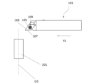
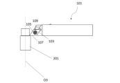
- the cutting tool 101 of the present disclosure has a rod shape extending from a tip 1a to a rear end 1b, as in a non-limiting example shown in Figs. 12 to 14.
- the cutting tool 101 has a holder 1 and a cutting insert 103 fixed to the holder 1.
- the cutting insert 103 may be located in a pocket 23 in the holder 1.
- the cutting insert 103 has a through hole 105.
- the cutting tool 101 has an insert screw 109 that can be used to fix the cutting insert 103 in the pocket 23.
- the pocket 23 may have a pocket hole 111 extending from the first upper surface 11 side toward the first lower surface 13 side.
- Materials for the cutting insert 103 include, for example, cemented carbide and cermet.
- Cemented carbide compositions include, for example, WC-Co, WC-TiC-Co, and WC-TiC-TaC-Co.
- WC-Co is produced by adding cobalt (Co) powder to tungsten carbide (WC) and sintering the mixture.
- WC-TiC-Co is produced by adding titanium carbide (TiC) to WC-Co.
- WC-TiC-TaC-Co is produced by adding tantalum carbide (TaC) to WC-TiC-Co.
- Cermets are sintered composite materials that combine ceramic components with metals.
- cermets include materials that contain titanium compounds such as titanium carbide (TiC) and titanium nitride (TiN) as the main component.
- the surface of the cutting insert 103 may be coated with a coating by chemical vapor deposition (CVD) or physical vapor deposition ( PVD ).
- the coating may have a composition such as titanium carbide (TiC), titanium nitride (TiN), titanium carbonitride (TiCN), and alumina ( Al2O3 ).
- the machined product is produced by cutting the workpiece 201.
- the manufacturing method of the machined product in the present disclosure includes the following steps. (C1) rotating the workpiece 201; (C2) contacting the cutting tool 101 with the rotating workpiece 201; (C3) a step of separating the cutting tool 101 from the workpiece 201; It is equipped with:
- the workpiece 201 is rotated around the rotation axis O3 and the cutting tool 101 is brought relatively close to the workpiece 201.
- the cutting edge 107 of the cutting tool 101 is brought into contact with the rotating workpiece 201 to cut the workpiece 201.
- the cutting tool 101 is moved relatively away from the workpiece 201.
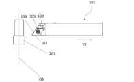
- the cutting tool 101 is moved in the Y1 direction while the workpiece 201 is rotating with the rotation axis O3 fixed, to bring it closer to the workpiece 201.
- the cutting edge 107 of the insert is brought into contact with the rotating workpiece 201 to cut the workpiece 201.
- the cutting tool 101 is moved in the Y2 direction while the workpiece 201 is rotating to move it away.
- the cutting tool 101 is moved in each step to bring the cutting tool 101 into contact with the workpiece 201 or to move the cutting tool 101 away from the workpiece 201, but it is not limited to this form.
- step (C1) the workpiece 201 may be brought closer to the cutting tool 101.
- step (C3) the workpiece 201 may be moved away from the cutting tool 101.
- the workpiece 201 may be kept rotating and the process of contacting the cutting edge 107 of the insert with different locations on the workpiece 201 may be repeated.
- examples of the material of the workpiece 201 include carbon steel, alloy steel, stainless steel, cast iron, and non-ferrous metals.
- a rod-shaped holder extending from a first end to a second end along a central axis has a first member located on the side of the first end, a second member located closer to the second end than the first member, and a fastener for fixing the first member to the second member
- the first member has a first end face located on the side of the second end, a first outer peripheral surface extending from the first end face toward the first end, and a second outer peripheral surface extending from the first end face toward the second end
- the second member has a protrusion having a first surface facing the second end and a first hole extending from the first surface toward the first end
- the second member has a second end surface located on the first end side and facing the first end surface, a second outer peripheral surface extending from the second end surface toward the second end, and a second hole extending from the second outer peripheral surface toward the first hole
- the fastener is inserted into the first hole through the second hole
- the protrusion may be located on the central hole
- the first surface may be located on the central axis.
- the end of the first member on the side of the second end may be located on the protrusion.
- the end of the first member on the side of the second end may be located on the first surface.
- the end of the second member on the side of the first end may be located on the second end surface.
- the fixture has a shaft portion extending along the axis of the fixture, and a head portion located closer to the second end than the shaft portion and having a larger outer diameter than the shaft portion, and the head portion may be separated from the first member.
- the protrusion may be spaced apart from the first outer circumferential surface.
- the protrusion when the first member is viewed from the second end side, the protrusion may be asymmetric with respect to the central axis.
- the first member when the first end surface is a first rear end surface, the first member may further have a first tip surface located on the first end side, the first outer peripheral surface may have an upper surface, a lower surface located opposite the upper surface, a first front surface located between the upper surface and the lower surface, and a pocket located on the first end side and opening at the first tip surface, the upper surface, and the first front surface, the second outer peripheral surface may have a second front surface facing the same side as the first front surface and a back surface facing the opposite side to the second front surface, and the second opening may be located on the back surface.
- the axis of the fixing device may be located closer to the bottom surface than the central axis.
- the fixture has a bottom portion located on the side of the first end and a head end portion located on the side of the second end, and an imaginary line segment connecting the center of the bottom portion and the center of the head end portion is the axis of the fixture, and when viewed from a direction perpendicular to the axis and central axis of the fixture, the length of the axis of the fixture in the direction along the central axis may be longer than the length of the axis of the fixture in the direction perpendicular to the central axis.
- the protrusion further has a peripheral wall portion connected to the first surface and the first end surface, the outer diameter of the protrusion decreases from the first end side toward the second end side, the first outer peripheral surface has an upper surface, and when viewed from the upper surface side, the inclination of the peripheral wall portion relative to the central axis may be smaller than the inclination of the axis of the fixing device relative to the central axis.
- the cutting tool may have a holder as described above in any one of (1) to (12) and a cutting insert fixed to the holder.
- a method for manufacturing a machined product may include a step of rotating a workpiece, a step of bringing the cutting tool described above in (13) into contact with the rotating workpiece, and a step of removing the cutting tool from the workpiece.
Landscapes
- Engineering & Computer Science (AREA)
- Mechanical Engineering (AREA)
- Cutting Tools, Boring Holders, And Turrets (AREA)
Priority Applications (1)
| Application Number | Priority Date | Filing Date | Title |
|---|---|---|---|
| JP2025503580A JPWO2024180831A1 (https=) | 2023-02-28 | 2023-11-24 |
Applications Claiming Priority (2)
| Application Number | Priority Date | Filing Date | Title |
|---|---|---|---|
| JP2023029999 | 2023-02-28 | ||
| JP2023-029999 | 2023-02-28 |
Publications (1)
| Publication Number | Publication Date |
|---|---|
| WO2024180831A1 true WO2024180831A1 (ja) | 2024-09-06 |
Family
ID=92589523
Family Applications (1)
| Application Number | Title | Priority Date | Filing Date |
|---|---|---|---|
| PCT/JP2023/042134 Ceased WO2024180831A1 (ja) | 2023-02-28 | 2023-11-24 | ホルダ、切削工具及び切削加工物の製造方法 |
Country Status (2)
| Country | Link |
|---|---|
| JP (1) | JPWO2024180831A1 (https=) |
| WO (1) | WO2024180831A1 (https=) |
Citations (3)
| Publication number | Priority date | Publication date | Assignee | Title |
|---|---|---|---|---|
| JPH0379203U (https=) * | 1989-11-30 | 1991-08-13 | ||
| US20060230890A1 (en) * | 2005-04-19 | 2006-10-19 | Roger Little | Miniature cutting insert holder |
| KR101442688B1 (ko) * | 2012-01-17 | 2014-09-19 | 구철회 | 절삭 공구 |
-
2023
- 2023-11-24 JP JP2025503580A patent/JPWO2024180831A1/ja active Pending
- 2023-11-24 WO PCT/JP2023/042134 patent/WO2024180831A1/ja not_active Ceased
Patent Citations (3)
| Publication number | Priority date | Publication date | Assignee | Title |
|---|---|---|---|---|
| JPH0379203U (https=) * | 1989-11-30 | 1991-08-13 | ||
| US20060230890A1 (en) * | 2005-04-19 | 2006-10-19 | Roger Little | Miniature cutting insert holder |
| KR101442688B1 (ko) * | 2012-01-17 | 2014-09-19 | 구철회 | 절삭 공구 |
Also Published As
| Publication number | Publication date |
|---|---|
| JPWO2024180831A1 (https=) | 2024-09-06 |
Similar Documents
| Publication | Publication Date | Title |
|---|---|---|
| JP6470405B2 (ja) | 切削インサート、切削工具及びこれを用いた切削加工物の製造方法 | |
| JPWO2015147214A1 (ja) | 切削インサート、切削工具及び切削加工物の製造方法 | |
| JPWO2019065525A1 (ja) | 切削インサート、切削工具及び切削加工物の製造方法 | |
| JP6462719B2 (ja) | 切削インサート、切削工具及び切削加工物の製造方法 | |
| JP7128185B2 (ja) | 切削インサート、切削工具及び切削加工物の製造方法 | |
| WO2016208536A1 (ja) | 切削インサート、切削工具及びこれを用いた切削加工物の製造方法 | |
| JP7102283B2 (ja) | ホルダ、切削工具及び切削加工物の製造方法 | |
| WO2024180831A1 (ja) | ホルダ、切削工具及び切削加工物の製造方法 | |
| JP7281532B2 (ja) | 旋削工具及び切削加工物の製造方法 | |
| JP7594672B2 (ja) | 切削インサート、切削工具及び切削加工物の製造方法 | |
| JP7756789B2 (ja) | 切削工具及び切削加工物の製造方法 | |
| JP7727750B2 (ja) | 切削工具及び切削加工物の製造方法 | |
| CN120344336A (zh) | 切削刀具以及切削加工物的制造方法 | |
| JP7784551B2 (ja) | 切削工具及び切削加工物の製造方法 | |
| JP7045460B2 (ja) | 切削工具及び切削加工物の製造方法 | |
| US20230415239A1 (en) | Cutting insert, cutting tool, and method for manufacturing machined product | |
| WO2016208771A1 (ja) | 切削工具及び切削加工物の製造方法 | |
| JP7527489B2 (ja) | ホルダ、切削工具及び切削加工物の製造方法 | |
| US20250196235A1 (en) | Cutting insert, cutting tool, and method for manufacturing machined product | |
| JP7117389B2 (ja) | 切削インサート、切削工具及び切削加工物の製造方法 | |
| JP2025150903A (ja) | ホルダ、切削工具、及び切削加工物の製造方法 | |
| JP2026060591A (ja) | ホルダ、切削工具、及び切削加工物の製造方法 | |
| WO2024209781A1 (ja) | 切削インサート、切削工具及び切削加工物の製造方法 | |
| JP2018034215A (ja) | 切削工具及び切削加工物の製造方法 | |
| WO2024224816A1 (ja) | 切削インサート、切削工具及び切削加工物の製造方法 |
Legal Events
| Date | Code | Title | Description |
|---|---|---|---|
| 121 | Ep: the epo has been informed by wipo that ep was designated in this application |
Ref document number: 23925383 Country of ref document: EP Kind code of ref document: A1 |
|
| WWE | Wipo information: entry into national phase |
Ref document number: 2025503580 Country of ref document: JP |
|
| NENP | Non-entry into the national phase |
Ref country code: DE |
|
| 122 | Ep: pct application non-entry in european phase |
Ref document number: 23925383 Country of ref document: EP Kind code of ref document: A1 |