WO2024180738A1 - 搬送システム - Google Patents
搬送システム Download PDFInfo
- Publication number
- WO2024180738A1 WO2024180738A1 PCT/JP2023/007643 JP2023007643W WO2024180738A1 WO 2024180738 A1 WO2024180738 A1 WO 2024180738A1 JP 2023007643 W JP2023007643 W JP 2023007643W WO 2024180738 A1 WO2024180738 A1 WO 2024180738A1
- Authority
- WO
- WIPO (PCT)
- Prior art keywords
- path unit
- transport path
- unit
- transport
- state
- Prior art date
- Legal status (The legal status is an assumption and is not a legal conclusion. Google has not performed a legal analysis and makes no representation as to the accuracy of the status listed.)
- Ceased
Links
Images


Classifications
-
- H—ELECTRICITY
- H02—GENERATION; CONVERSION OR DISTRIBUTION OF ELECTRIC POWER
- H02P—CONTROL OR REGULATION OF ELECTRIC MOTORS, ELECTRIC GENERATORS OR DYNAMO-ELECTRIC CONVERTERS; CONTROLLING TRANSFORMERS, REACTORS OR CHOKE COILS
- H02P29/00—Arrangements for regulating or controlling electric motors, appropriate for both AC and DC motors
- H02P29/60—Controlling or determining the temperature of the motor or of the drive
- H02P29/68—Controlling or determining the temperature of the motor or of the drive based on the temperature of a drive component or a semiconductor component
-
- G—PHYSICS
- G05—CONTROLLING; REGULATING
- G05B—CONTROL OR REGULATING SYSTEMS IN GENERAL; FUNCTIONAL ELEMENTS OF SUCH SYSTEMS; MONITORING OR TESTING ARRANGEMENTS FOR SUCH SYSTEMS OR ELEMENTS
- G05B19/00—Program-control systems
- G05B19/02—Program-control systems electric
- G05B19/418—Total factory control, i.e. centrally controlling a plurality of machines, e.g. direct or distributed numerical control [DNC], flexible manufacturing systems [FMS], integrated manufacturing systems [IMS] or computer integrated manufacturing [CIM]
- G05B19/4189—Total factory control, i.e. centrally controlling a plurality of machines, e.g. direct or distributed numerical control [DNC], flexible manufacturing systems [FMS], integrated manufacturing systems [IMS] or computer integrated manufacturing [CIM] characterised by the transport system
-
- B—PERFORMING OPERATIONS; TRANSPORTING
- B65—CONVEYING; PACKING; STORING; HANDLING THIN OR FILAMENTARY MATERIAL
- B65G—TRANSPORT OR STORAGE DEVICES, e.g. CONVEYORS FOR LOADING OR TIPPING, SHOP CONVEYOR SYSTEMS OR PNEUMATIC TUBE CONVEYORS
- B65G54/00—Non-mechanical conveyors not otherwise provided for
- B65G54/02—Non-mechanical conveyors not otherwise provided for electrostatic, electric, or magnetic
-
- H—ELECTRICITY
- H02—GENERATION; CONVERSION OR DISTRIBUTION OF ELECTRIC POWER
- H02K—DYNAMO-ELECTRIC MACHINES
- H02K1/00—Details of the magnetic circuit
- H02K1/06—Details of the magnetic circuit characterised by the shape, form or construction
- H02K1/22—Rotating parts of the magnetic circuit
- H02K1/27—Rotor cores with permanent magnets
-
- H—ELECTRICITY
- H02—GENERATION; CONVERSION OR DISTRIBUTION OF ELECTRIC POWER
- H02K—DYNAMO-ELECTRIC MACHINES
- H02K41/00—Propulsion systems in which a rigid body is moved along a path due to dynamo-electric interaction between the body and a magnetic field travelling along the path
- H02K41/02—Linear motors; Sectional motors
- H02K41/03—Synchronous motors; Motors moving step by step; Reluctance motors
- H02K41/031—Synchronous motors; Motors moving step by step; Reluctance motors of the permanent magnet type
-
- H—ELECTRICITY
- H02—GENERATION; CONVERSION OR DISTRIBUTION OF ELECTRIC POWER
- H02P—CONTROL OR REGULATION OF ELECTRIC MOTORS, ELECTRIC GENERATORS OR DYNAMO-ELECTRIC CONVERTERS; CONTROLLING TRANSFORMERS, REACTORS OR CHOKE COILS
- H02P25/00—Arrangements or methods for the control of AC motors characterised by the kind of AC motor or by structural details
- H02P25/02—Arrangements or methods for the control of AC motors characterised by the kind of AC motor or by structural details characterised by the kind of motor
- H02P25/06—Linear motors
-
- H—ELECTRICITY
- H02—GENERATION; CONVERSION OR DISTRIBUTION OF ELECTRIC POWER
- H02P—CONTROL OR REGULATION OF ELECTRIC MOTORS, ELECTRIC GENERATORS OR DYNAMO-ELECTRIC CONVERTERS; CONTROLLING TRANSFORMERS, REACTORS OR CHOKE COILS
- H02P25/00—Arrangements or methods for the control of AC motors characterised by the kind of AC motor or by structural details
- H02P25/02—Arrangements or methods for the control of AC motors characterised by the kind of AC motor or by structural details characterised by the kind of motor
- H02P25/06—Linear motors
- H02P25/064—Linear motors of the synchronous type
-
- H—ELECTRICITY
- H02—GENERATION; CONVERSION OR DISTRIBUTION OF ELECTRIC POWER
- H02P—CONTROL OR REGULATION OF ELECTRIC MOTORS, ELECTRIC GENERATORS OR DYNAMO-ELECTRIC CONVERTERS; CONTROLLING TRANSFORMERS, REACTORS OR CHOKE COILS
- H02P29/00—Arrangements for regulating or controlling electric motors, appropriate for both AC and DC motors
- H02P29/02—Providing protection against overload without automatic interruption of supply
- H02P29/024—Detecting a fault condition, e.g. short circuit, locked rotor, open circuit or loss of load
- H02P29/027—Detecting a fault condition, e.g. short circuit, locked rotor, open circuit or loss of load the fault being an over-current
-
- H—ELECTRICITY
- H02—GENERATION; CONVERSION OR DISTRIBUTION OF ELECTRIC POWER
- H02P—CONTROL OR REGULATION OF ELECTRIC MOTORS, ELECTRIC GENERATORS OR DYNAMO-ELECTRIC CONVERTERS; CONTROLLING TRANSFORMERS, REACTORS OR CHOKE COILS
- H02P29/00—Arrangements for regulating or controlling electric motors, appropriate for both AC and DC motors
- H02P29/60—Controlling or determining the temperature of the motor or of the drive
-
- H—ELECTRICITY
- H02—GENERATION; CONVERSION OR DISTRIBUTION OF ELECTRIC POWER
- H02P—CONTROL OR REGULATION OF ELECTRIC MOTORS, ELECTRIC GENERATORS OR DYNAMO-ELECTRIC CONVERTERS; CONTROLLING TRANSFORMERS, REACTORS OR CHOKE COILS
- H02P6/00—Arrangements for controlling synchronous motors or other dynamo-electric motors using electronic commutation dependent on the rotor position; Electronic commutators therefor
- H02P6/34—Modelling or simulation for control purposes
-
- H—ELECTRICITY
- H02—GENERATION; CONVERSION OR DISTRIBUTION OF ELECTRIC POWER
- H02K—DYNAMO-ELECTRIC MACHINES
- H02K11/00—Structural association of dynamo-electric machines with electric components or with devices for shielding, monitoring or protection
- H02K11/20—Structural association of dynamo-electric machines with electric components or with devices for shielding, monitoring or protection for measuring, monitoring, testing, protecting or switching
- H02K11/25—Devices for sensing temperature, or actuated thereby
-
- H—ELECTRICITY
- H02—GENERATION; CONVERSION OR DISTRIBUTION OF ELECTRIC POWER
- H02K—DYNAMO-ELECTRIC MACHINES
- H02K11/00—Structural association of dynamo-electric machines with electric components or with devices for shielding, monitoring or protection
- H02K11/30—Structural association with control circuits or drive circuits
Definitions
- This disclosure relates to a transport system for transporting objects.
- conveyor systems are commonly used to transport workpieces.
- conveyor systems have been widely used in which the transport path along which the workpieces are transported is divided into multiple zones, and carts carrying the workpieces are driven by control devices located in each zone. This type of conveyor system is known as one of the conveyor systems with superior production efficiency.
- One type of transport system uses a so-called moving magnet type linear motor, in which a magnet is placed on the carriage, which acts as the mover, and a coil is placed on the stator that forms the transport path.
- a moving magnet type linear motor is suitable for moving a mover with a stroke that is long compared to the length of the mover. Multiple coils are lined up on the transport path in the direction in which the mover is moved.
- Patent document 1 discloses a system that includes a carriage as a transport body and multiple coils arranged on a transport path, generates a magnetic field by passing an electric current through each coil, and moves the carriage by the action of the magnetic field.
- This disclosure has been made in consideration of the above, and aims to provide a transport system that provides overload protection appropriate for the operation of the transport system.
- the transport system includes a plurality of transport path units constituting a transport path along which one or a plurality of transport bodies move.
- Each of the plurality of transport path units has a plurality of drive units that generate a thrust for moving the transport body by flowing an electric current, and a processor that determines whether each of the plurality of drive units is in an overloaded state, and determines whether the transport path unit is in an overloaded state.
- the processor executes an overload protection process that reduces the temperature of a drive unit determined to be in an overloaded state or the temperature of a transport path unit determined to be in an overloaded state.
- the conveying system disclosed herein has the effect of enabling overload protection that is appropriate for the operation of the conveying system.
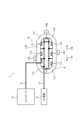
- FIG. 1 is a diagram showing a configuration example of a transport system according to a first embodiment
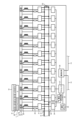
- FIG. 1 is a diagram showing a configuration example of a transport path unit provided in the transport system according to the first embodiment
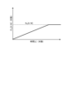
- FIG. 1 is a diagram for explaining thermal resistance of elements constituting a driving unit in a transport system according to a first embodiment
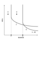
- FIG. 1 is a diagram showing an example of a first overload judgment curve that is a first criterion for judging an overload state in the transport system according to the first embodiment
- FIG. 1 is a first diagram for explaining a worst-case loss of a transport path unit in a transport system according to a first embodiment
- FIG. 2 is a second diagram for explaining the worst loss of the transport path unit in the transport system according to the first embodiment
- FIG. 13 is a diagram showing an example of a second overload judgment curve that is a second criterion for judging an overload state in the transport system according to the first embodiment
- FIG. 1 is a first diagram for explaining a maximum rated loss of a transport path unit in a transport system according to a first embodiment
- FIG. 2 is a second diagram for explaining the maximum rated loss of the transport path unit in the transport system according to the first embodiment
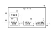
- FIG. 13 is a diagram showing a configuration example of a controller provided in a transport system according to a fourth embodiment
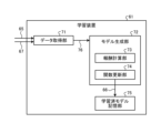
- FIG. 13 is a diagram showing a configuration example of a learning device provided in a controller according to a fourth embodiment
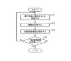
- 13 is a flowchart showing a processing procedure of a learning device provided in a controller according to a fourth embodiment.
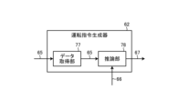
- FIG. 13 is a diagram showing a configuration example of an operation command generator provided in a controller according to a fourth embodiment
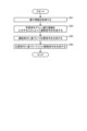
- 11 is a flowchart showing the processing procedures of an operation command generator, a position command generator, and a coil drive command generator provided in a controller according to a fourth embodiment.
- FIG. 1 shows an example of the configuration of a control circuit according to first to fourth embodiments
- FIG. 1 is a diagram showing an example of a configuration of a dedicated hardware circuit according to first to fourth embodiments;
- Embodiment 1. 1 is a diagram showing a configuration example of a conveyance system 1 according to a first embodiment.
- the conveyance system 1 is a system used for conveying objects.
- the conveyance system 1 conveys objects by moving a conveyance body on which the objects are placed.
- the transport system 1 comprises multiple transport path units 11A-11H, a controller 12, a direct current (DC) power supply 13, and carts 16A, 16B, and 16C.
- the controller 12 controls the operation of each of the carts 16A, 16B, and 16C via the transport path units 11A-11H.
- the transport path unit 11 refers to each of the transport path units 11A-11H without distinction.
- the multiple transport path units 11 are connected to each other and form the transport path 10 along which the transport body moves.
- the multiple transport path units 11 move the transport body by applying power to the transport body.
- Each of the carriages 16A, 16B, and 16C is a transport body. In the following description, the carriage 16 refers to each of the carriages 16A, 16B, and 16C without distinction.
- the conveying path 10 shown in FIG. 1 is circular. That is, the conveying path 10 shown in FIG. 1 is a closed path.
- the conveying path 10 of the conveying system 1 may be an open path. That is, the conveying path 10 of the conveying system 1 may be a path having a start point and an end point that are located apart from each other.
- the transport path units 11A, 11B, 11E, and 11F are linear transport path units 11 that form a linear path.
- the transport path units 11C, 11D, 11G, and 11H are curved transport path units 11 that form a curved path, and change the traveling direction of the transport body.
- the transport path 10 may not have transport path units 11 that form a linear path, and may consist only of transport path units 11 that form a curved path.
- a transport path 10 having a start point and an end point that are located at positions separated from each other may consist only of transport path units 11 that form a linear path.
- the overall shape of the transport path 10 is arbitrary.
- the cart 16 is attached to the side of the conveying path 10.
- the cart 16 moves along a guide rail provided on the side of the conveying path 10.
- the cart 16 moves on the side of the conveying path 10 and stops on the side of the conveying path 10.
- the conveying system 1 is a moving magnet type linear motor.
- the cart 16 may move along a guide rail provided on the upper surface of the conveying path 10.
- the cart 16 includes a permanent magnet that constitutes the mover, a permanent magnet for the linear scale, and a guide roller that moves on the guide rail by rotating. In FIG. 1, the guide rail, the guide roller, the permanent magnet that constitutes the mover, and the permanent magnet for the linear scale are not shown.
- the traveling direction of each cart 16 is either clockwise in FIG. 1 or counterclockwise in FIG. 1.
- the clockwise direction in FIG. 1 is the forward direction.
- the counterclockwise direction in FIG. 1 is the reverse direction.
- Arrow 17A indicates the forward direction.
- Arrow 17B indicates the reverse direction.
- the transport system 1 includes eight transport path units 11 and three carts 16.
- the number of transport path units 11 included in the transport system 1 is arbitrary. In other words, the number of transport path units 11 that make up the transport path 10 is arbitrary.
- the transport system 1 may include multiple transport path units 11.
- the number of carts 16 that move on the transport path 10 is arbitrary.
- the transport system 1 may include one or multiple carts 16.
- the conveying system 1 is not limited to a system equipped with a linear motor, and may be a system equipped with a rotary motor.
- the conveying system 1 may be a belt conveyor equipped with a rotary motor and a belt rotated by the rotary motor.
- the belt conveyor moves workpieces placed on the belt.
- the conveying system 1 may be a roller conveyor equipped with multiple rollers and a rotary motor that rotates the rollers.
- the roller conveyor moves workpieces placed on the rollers.
- the DC power supply 13 is connected to each transport path unit 11 via a DC power supply bus 15.
- the DC power supply 13 is a power supply device or power supply circuit that outputs a direct current voltage.
- the DC power supply 13 supplies power to each transport path unit 11.
- Each transport path unit 11 shares the DC power supply 13.
- the DC power bus 15 has a positive DC busbar and a negative DC busbar.
- the positive DC busbar is called the P busbar.
- the negative DC busbar is called the N busbar.
- the P busbar is connected to the positive pole of the DC power source 13.
- the N busbar is connected to the negative pole of the DC power source 13.
- PN busbar When referring to both the P busbar and the N busbar, they will be referred to as the PN busbar.
- Each of the multiple transport path units 11 that make up the transport path 10 is connected to a common PN busbar.
- the transport system 1 has a configuration in which each transport path unit 11 is connected to a DC power source 13 by a multi-drop connection.
- the connection between each transport path unit 11 and the DC power source 13 is not limited to a multi-drop connection, and may be a daisy chain connection.
- the transport system 1 is provided with one DC power source 13, but the transport system 1 may be provided with multiple DC power sources 13. In other words, the transport system 1 may be configured with multiple power source domains.
- the controller 12 is connected to each transport path unit 11 via a data communication line 14.
- the data communication line 14 is composed of a line that connects the transport path unit 11A, which is one of the multiple transport path units 11, to the controller 12, and a line that connects adjacent transport path units 11 to each other.
- the transport system 1 has a configuration in which each transport path unit 11 is connected to the controller 12 by a daisy chain connection.
- each transport path unit 11 and the controller 12 is not limited to a daisy chain connection.
- the connection between each transport path unit 11 and the controller 12 may be a star connection in which each transport path unit 11 is connected to the controller 12 via a communication hub.
- the transport system 1 may be provided with multiple data communication lines 14, and each transport path unit 11 and the controller 12 may be directly connected by the data communication lines 14.
- the controller 12 generates driving commands indicating the manner of movement for each of the multiple trolleys 16, and generates a position command for each trolley 16 based on the driving commands.
- the driving commands include information such as acceleration, deceleration, and movement speed.
- the controller 12 generates a coil drive command based on the position command for each trolley 16.
- the controller 12 outputs a coil drive command to each transport path unit 11.
- the coil drive command includes a current command indicating a command value for the current to be passed through each coil of the transport path unit 11.
- Each transport path unit 11 controls the current flowing through each coil according to the current command included in the coil drive command.
- the controller 12 controls the movement of each trolley 16 by outputting a coil drive command to each transport path unit 11.
- a control device that is higher than the controller 12, such as a programmable logic controller, may be connected to the controller 12. Such a control device outputs commands for sequence control to the controller 12.
- a human-machine interface may be connected to the controller 12. An operator operates the human-machine interface to input information to the human-machine interface. The human-machine interface also outputs information indicating the status of the transport system 1. The human-machine interface displays, for example, information indicating the status of the transport system 1.
- the controller 12 may obtain operation information of the carts 16 from the higher-level control device or human-machine interface, and generate a position command based on the operation information.
- the operation information is information that indicates a schedule for the movement of each of the multiple carts 16 on the transport path 10.
- the operation information includes information on the movement start position, stop position, movement time, etc.
- the configuration of the transport path unit 11 will be described.
- the configuration of the transport path unit 11 will be described using a straight-type transport path unit 11 as an example.
- the coil arrangement is different from that in the case of a straight-type transport path unit 11.
- the configuration of the curved-type transport path unit 11 is similar to the configuration of the straight-type transport path unit 11, except for the difference in the coil arrangement.
- FIG. 2 is a diagram showing an example of the configuration of the transport path unit 11 provided in the transport system 1 according to the first embodiment.
- FIG. 2 shows a schematic configuration of the transport path unit 11 and a schematic configuration of the carriage 16 present on the transport path unit 11.
- the carriage 16 has a permanent magnet 40 that constitutes a mover and a permanent magnet 41 for a linear scale.
- one north pole magnet and one south pole magnet are shown as the permanent magnets 40 that make up the mover, but the permanent magnets 40 that make up the mover can have any number of north pole magnets and any number of south pole magnets.
- the north pole magnets and south pole magnets are arranged alternately along the direction in which the multiple coils 20 described below are arranged.
- the cart 16 moves by obtaining a driving force due to the interaction between the electromagnetic force generated by the coils 20 described below that the transport path unit 11 has and the magnetic field generated by the permanent magnets 40 that make up the mover.
- FIG. 2 four north pole magnets and four south pole magnets are shown as the permanent magnet 41 for the linear scale. As shown in FIG. 2, in the permanent magnet 41, the north pole magnets and the south pole magnets are arranged alternately along the direction in which the multiple coils 20 described below are arranged.
- the permanent magnet 41 for the linear scale can have any number of north pole magnets and any number of south pole magnets.
- the transport path unit 11 includes multiple coils 20.
- the transport path unit 11 includes 12 coils 20.
- the number of coils 20 included in the transport path unit 11 is arbitrary.
- the multiple coils 20 are arranged along a linear path.
- the multiple coils 20 are arranged along a curved path.
- Each coil 20 of the transport path unit 11 includes not only a pure inductance component but also coil resistance.
- An inverter 21 is connected to each coil 20 of the transport path unit 11.
- the inverter 21 includes a switching element, and supplies the coil 20 with power that has been converted by switching the switching element. The switching element is not shown.
- the inverter 21 controls the current flowing through the coil 20.
- the inverter 21 is a single-phase full-bridge inverter circuit or a single-phase half-bridge inverter circuit.
- the inverter 21 may be a three-phase inverter circuit connected to three coils 20.
- Each inverter 21 of the conveying path unit 11 is connected between a P bus 31, which is the positive wiring of the DC power supply bus 15, and an N bus 32, which is the negative wiring of the DC power supply bus 15.
- Each inverter 21 converts DC power from the PN bus into AC power and supplies the AC power to the coil 20.
- the inverter 21 performs power conversion from DC power to AC power by switching the switching element.
- the coil 20 generates electromagnetic force, which is a thrust force that moves the cart 16, by receiving power from the inverter 21.
- the coil 20 and the inverter 21 function as a drive unit that generates a thrust force that moves the cart 16 by passing an electric current through them.
- the transport path unit 11 is equipped with multiple drive units.
- a current sensor 22 is connected to each coil 20 of the transport path unit 11.
- the current sensor 22 detects the actual coil current value, which is the current value of the current flowing through the coil 20.
- a capacitor 23, which is an electrolytic capacitor is connected between the P bus 31 and the N bus 32. By providing the capacitor 23, sudden voltage fluctuations in the PN bus are prevented in the transport path unit 11.
- a voltage detector 33 is connected between the P bus 31 and the N bus 32. The voltage detector 33 detects the bus voltage, which is the voltage between the P bus 31 and the N bus 32, based on the potential of the N bus 32. The voltage detector 33 outputs the detection result of the bus voltage to the processor 27.
- a current controller 24 that controls each inverter 21 of the conveying path unit 11 is connected to each inverter 21.
- the current controller 24 calculates the voltage value of the voltage to be applied to the coil 20 based on the command value of the current to be passed through the coil 20 and the actual coil current value detected by the current sensor 22.
- the current controller 24 transmits a pulse width modulation (PWM) signal obtained by comparing the calculated voltage value with a triangular wave to the inverter 21.
- PWM pulse width modulation
- the current controller 24 causes the inverter 21 to perform switching by transmitting a PWM signal to the inverter 21.
- the current controller 24 applies a voltage to the coil 20 for passing a current of a desired current value through the coil 20.
- the current controller 24 may calculate the voltage value of the voltage to be applied to the coil 20 by performing PID (Proportional Integral Differential) control of the voltage to be applied to the coil 20 based on the deviation between the current command value and the actual coil current value. In addition, the current controller 24 outputs the actual coil current value detected by the current sensor 22 to the processor 27.
- PID Proportional Integral Differential
- the transport path unit 11 includes a linear scale 25, a processor 27, and a communication slave station 28.
- the linear scale 25 is a detection unit that detects the position of the cart 16 on the transport path unit 11.
- the linear scale 25 is provided on the transport path 10 when multiple transport path units 11 are connected to each other to form the transport path 10.
- the processor 27 is a CPU (Central Processing Unit).
- the processor 27 may be an arithmetic device, a processing device, a microprocessor, a microcomputer, or a DSP (Digital Signal Processor).
- the linear scale 25 includes a plurality of position sensors 26.
- Each position sensor 26 is a sensor that detects a magnetic field, such as a Hall sensor or a magnetic resistance sensor.
- Each position sensor 26 detects the magnetic field of the permanent magnet 40 or the magnetic field of the permanent magnet 41.
- the position sensor 26 is a Hall sensor equipped with two Hall elements. The distance between the two Hall elements is equivalent to half the magnetic pole pitch of the permanent magnet 41.
- Each Hall element converts the magnetic field into an electric signal and outputs the electric signal.
- the electric signal output by each Hall element changes with the movement of the trolley 16.
- the waveform of the electric signal output by one Hall element in the position sensor 26 is a sine wave.
- the waveform of the electric signal output by the other Hall element in the position sensor 26 is a cosine wave.
- the electrical signals from each position sensor 26 of the linear scale 25 are input to the processor 27.
- An AD (Analog to Digital) converter provided with the processor 27 detects sine waves and cosine waves.
- the processor 27 detects the position of the trolley 16 with respect to the position sensor 26 by calculating the arctan based on the sine wave information and cosine wave information. In this way, the processor 27 obtains position sensor information that indicates the relative position of the trolley 16 with respect to the position sensor 26. Note that communication lines between each position sensor 26 and the processor 27 are not shown in FIG. 2.
- the processor 27 obtains the voltage value, which is the detection result of the bus voltage, from the voltage detector 33.
- the processor 27 obtains the actual coil current value from the current controller 24.
- the processor 27 performs a calculation that incorporates the actual coil current value. The determination of whether or not there is an overload state will be described later.
- the communication slave station 28 is a communication slave station on the transport path unit 11 side.
- the data communication line 14 is connected to the communication slave station 28.
- the communication slave station 28 is configured to be able to connect the two lines that make up the data communication line 14.
- the communication slave station 28 receives a coil drive command transmitted from the controller 12.
- the communication slave station 28 transmits a current command contained in the coil drive command to each of the multiple current controllers 24.
- the transport path unit 11 controls the current flowing through each of the multiple coils 20 in accordance with the coil drive command.
- the communication slave 28 also acquires position sensor information from the processor 27.
- the communication slave 28 transmits the acquired position sensor information to the controller 12.
- the communication slave 28 performs, for example, periodic communication in which it receives coil drive commands at a fixed period and transmits position sensor information. Instead of such periodic communication, the communication slave 28 may receive coil drive commands and transmit position sensor information non-periodically.
- the transport path unit 11 is equipped with a temperature sensor 34.
- the temperature sensor 34 measures the temperature of the transport path unit 11.
- the temperature sensor 34 outputs the temperature measurement result to the processor 27.
- the processor 27 monitors the temperature measured by the temperature sensor 34.
- the transport path unit 11 mainly has the function of controlling the current supply to the coil 20 and the function of acquiring position sensor information.
- Each of the multiple transport path units 11 that make up the transport path 10 similarly controls the current supply to the coil 20 and similarly acquires position sensor information.
- overload protection in the transport path unit 11 will be described.
- the processor 27 determines whether each of the multiple drive units is in an overloaded state, and determines whether the transport path unit 11 is in an overloaded state.
- the processor 27 executes an overload protection process to lower the temperature of the drive unit determined to be in an overloaded state or the temperature of the transport path unit 11 determined to be in an overloaded state.
- the drive unit being in an overloaded state means that the elements that make up the drive unit are in an overheated state. In other words, the drive unit being in an overloaded state means that the temperature of the elements that make up the drive unit exceeds the temperature at which the elements can continue to operate normally.
- the transport path unit 11 being in an overloaded state means that the entire interior of the transport path unit 11 is in an overheated state. In other words, the transport path unit 11 being in an overloaded state means that the temperature inside the transport path unit 11 exceeds the temperature at which each of the elements provided inside the transport path unit 11 can continue to operate normally.
- the elements provided inside the transport path unit 11 include elements that make up the drive unit and elements other than the elements that make up the drive unit. Elements other than the elements that make up the drive unit include, for example, the capacitor 23 or the processor 27.
- Processor 27 monitors whether or not one or more elements included in the drive unit are in an overload state.
- the drive unit includes elements to be monitored for whether or not they are in an overload state.
- inverter 21, which is the first element included in the drive unit, and coil 20, which is the second element included in the drive unit, are assumed to be the elements to be monitored.
- Each of the coil 20 and the inverter 21 has an electrical resistance component.
- the coil 20 generates losses according to the current value of the current flowing through the coil 20.
- the inverter 21 generates losses according to the current value of the current flowing through the inverter 21.
- the coil resistance is the cause of losses.
- the inverter 21 is equipped with semiconductor switching elements such as MOSFETs (Metal Oxide Semiconductor Field Effect Transistors) or IGBTs (Insulated Gate Bipolar Transistors) and diodes for commutation. In the inverter 21, losses may occur due to resistance when a current is passed through the MOSFET or IGBT, or forward losses in the diodes.
- MOSFETs Metal Oxide Semiconductor Field Effect Transistors
- IGBTs Insulated Gate Bipolar Transistors
- the transport path unit 11 provides overload protection for the coil 20 and the inverter 21, which are elements that make up the drive unit.
- ⁇ T is expressed by the following formula (1): R th [K/W] is the thermal resistance of the element and represents the thermal resistance in the steady state; P [W] represents the loss.
- R th Rth ⁇ P...(1)
- Processor 27 acquires the actual coil current value from current controller 24. Processor 27 calculates the effective value of the current flowing through the element constituting the drive unit based on the actual coil current value. The current value at which the element's temperature becomes the allowable temperature of the element as a result of current flowing through the element is set to the maximum rated current value. If the effective value of the current flowing through the element constituting the drive unit is equal to or less than the maximum rated current value of the element, it is possible to continuously flow current through the element.
- the thermal resistance of the elements that make up the drive unit also includes thermal resistance due to transient losses. Thermal resistance due to transient losses is called transient thermal resistance. Even if a current that exceeds the maximum rated current value of an element flows through that element, the element will not be destroyed if the current flows for a short period of time and the element's temperature falls below the allowable temperature.
- Fig. 3 is a diagram for explaining the thermal resistance of elements constituting the driving unit in the transport system 1 according to the first embodiment.
- Fig. 3 shows a graph showing the relationship between the transient thermal resistance and time.
- the vertical axis shown in Fig. 3 represents the transient thermal resistance ⁇ th [K/W].
- the horizontal axis shown in Fig. 3 represents time [s]. Both the vertical axis in Fig. 3 and the horizontal axis in Fig. 3 are on a logarithmic scale.
- the transient thermal resistance increases as time increases, and becomes constant when the time exceeds a certain time.
- the value of the transient thermal resistance when it becomes constant is equal to the value of Rth , which is the thermal resistance in the steady state.
- FIG. 4 is a diagram showing an example of a first overload judgment curve that is the first judgment criterion for an overload state in the conveyance system 1 according to the first embodiment.
- the first overload judgment curve which is the first judgment criterion, represents the relationship between a first load judgment value and time.
- the first load judgment value is a threshold value of the current flowing through an element when the element is not in an overload state and when the element is in an overload state.
- the vertical axis shown in FIG. 4 represents time [s].
- the horizontal axis shown in FIG. 4 represents the current effective value, which is the effective value of the current flowing through the element. It can also be said that the horizontal axis shown in FIG. 4 represents the amount of load applied to the element.
- the processor 27 uses the first criterion, which is the relationship between the first load judgment value and the time during which current flows through the element, i.e., the preset first overload judgment curve, to compare the effective value of the current flowing through the element constituting the drive unit and the time during which current flows through the element constituting the drive unit with the first overload judgment curve to judge whether the element is in an overload state.
- the processor 27 judges whether the element constituting the drive unit is in an overload state by comparing the first criterion with the effective value of the current flowing through the element constituting the drive unit and the time during which current flows through the element.
- the first overload judgment curve which is the first criterion, may be preset in the processor 27, or the processor 27 may read out the first overload judgment curve that is preset by recording it on a recording medium, and use the first overload judgment curve in the operation of the processor 27.
- Curve 51 shown in FIG. 4 is an example of a first overload judgment curve for coil 20.
- Curve 52 shown in FIG. 4 is an example of a first overload judgment curve for inverter 21.
- the effective current value which is the first load judgment value, decreases as time increases and becomes constant when the time exceeds a certain time.
- I1 which is the effective current value when the effective current value becomes constant
- I2 which is the effective current value when the effective current value becomes constant
- I2 which is the effective current value when the effective current value becomes constant, is the maximum rated current value of inverter 21.
- Points 53, 54, and 55 each represent a current conduction pattern that is a combination of the time during which current flows through the coil 20 and the inverter 21 and the effective value of the current flowing through the coil 20 and the inverter 21.
- the effective value of the current flowing through the coil 20 and the inverter 21, which are elements that constitute the drive unit is smaller than the maximum rated current value of the coil 20 and is also smaller than the maximum rated current value of the inverter 21.
- the processor 27 determines that neither the coil 20 nor the inverter 21 is in an overload state. In other words, the processor 27 determines that the drive unit is not in an overload state.
- the effective value of the current flowing through the coil 20 and the inverter 21, which are elements constituting the drive unit is greater than the maximum rated current value of the coil 20 and greater than the maximum rated current value of the inverter 21.
- the effective value of the current flowing through the coil 20 and the inverter 21 is smaller than the first load judgment value represented by the curve 51 and smaller than the first load judgment value represented by the curve 52.
- the processor 27 determines that neither the coil 20 nor the inverter 21 is in an overload state. In other words, the processor 27 determines that the drive unit is not in an overload state.
- the effective value of the current flowing through the coil 20 and inverter 21, which are elements constituting the drive unit is greater than the maximum rated current value of the coil 20 and less than the maximum rated current value of the inverter 21.
- the effective current value of the current flowing through the coil 20 and inverter 21 is greater than the first load judgment value represented by curve 51.
- the processor 27 determines that the inverter 21 is not in an overload state, but the coil 20 is in an overload state. Since the coil 20 is in an overload state, the processor 27 determines that the drive unit is in an overload state.
- the processor 27 judges whether or not the drive unit is in an overload state based on the effective value of the current flowing through the element and the time that the current flows through the element.
- the objects to be monitored in the drive unit are the coil 20 and the inverter 21, but the objects to be monitored may be either the coil 20 or the inverter 21. Furthermore, elements other than the coil 20 and the inverter 21 may also be included in the objects to be monitored. Any element through which a current flows may be monitored.
- the processor 27 judges whether or not the drive unit is in an overload state using an overload judgment curve that matches the elements that make up the drive unit to be monitored.
- the processor 27 acquires the actual coil current value from the current controller 24, it performs first-order lag filtering of the actual coil current value.
- the processor 27 determines whether or not each of the coil 20 and the inverter 21 is in an overload state by comparing the current flow pattern, which is a combination of the actual coil current value after first-order lag filtering and the time during which current flows through the coil 20 and the inverter 21, with a first overload determination curve.
- the processor 27 has the function of determining whether or not the coil 20 and the inverter 21 provided in each of the multiple drive units provided in the transport path unit 11 are in an overload state in this manner.
- the processor 27 transmits an alarm indicating an overloaded state to each transport path unit 11 of the transport system 1.
- the processor 27 of each transport path unit 11 executes overload protection processing when the transport path unit 11 receives an alarm.
- the current controller 24 stops the power supply to each drive unit.
- the processor 27 of each transport path unit 11 controls to stop all the carts 16 present in the transport system 1.
- the multiple transport path units 11 stop all the carts 16 present on the transport path 10 by overload protection processing.
- the overload protection processing in this case is a process of lowering the temperature of the drive units by reducing the load on the coil 20 and the load on the inverter 21 to zero.
- Each transport path unit 11 may perform overload protection processing to decelerate and then stop each cart 16. Each transport path unit 11 may perform overload protection processing to activate regenerative braking by shorting the coil 20.
- the processor 27 of each transport path unit 11 may also perform overload protection processing to reduce the amount of current flowing to each drive unit. In this case, the processor 27 of each transport path unit 11 decelerates all carts 16 present in the transport system 1 by controlling to reduce the amount of current.
- the overload protection processing in this case is processing to reduce the temperature of the drive units by reducing the load on the coil 20 and the load on the inverter 21.
- the multiple transport path units 11 may slow down all of the carts 16 present on the transport path 10 through overload protection processing.
- the transport system 1 can avoid problems such as burnout due to overheating.
- all the trolleys 16 present on the conveying path 10 are stopped or decelerated by the overload protection process, but the overload protection process executed by the conveying system 1 is not limited to this.
- the overload protection process executed by the conveying system 1 is not limited to this.
- only the conveying path unit 11 including the drive unit determined to be in an overloaded state may stop or decelerate the trolley 16 by the overload protection process.
- the trolleys 16 present on the conveying path 10 composed of the conveying path units 11 other than the conveying path unit 11 including the drive unit determined to be in an overloaded state are not stopped or decelerated.
- the processor 27 stops the power supply to each drive unit or reduces the amount of current flowing to each drive unit only in the transport path unit 11 that includes the drive unit determined to be in an overloaded state.
- the transport system 1 can also avoid problems such as burnout due to overheating.
- the overload protection process may be to stop the flow of electricity only to the drive unit determined to be in an overloaded state.
- the transport system 1 can avoid problems such as burnout due to overheating.
- the processor 27 determines whether or not the transport path unit 11 is in an overloaded state. In each of the multiple transport path units 11, the processor 27 executes an overload protection process to lower the temperature of the transport path unit 11 that has been determined to be in an overloaded state.
- the coil 20 and inverter 21 which are elements that make up the drive unit, electronic components such as a capacitor 23 and a processor 27 are provided inside the housing of the transport path unit 11.
- the allowable temperature of the capacitor 23 and the allowable temperature of the processor 27 are lower than the allowable temperature of the coil 20 or the allowable temperature of the inverter 21.
- the worst loss of the transport path unit 11 is defined as the loss when the current value flowing through all the coils 20 of the transport path unit 11 is the maximum rated current value of the coils 20.
- the worst loss of the transport path unit 11 is expressed by the following formula (3).
- R coil [ ⁇ ] represents the resistance value of the coil 20.
- R inv [ ⁇ ] represents the resistance of the inverter 21 when it is energized.
- I crated [Arms] represents the maximum rated current value of the coil 20.
- Worst case loss of the transport path unit 12 ⁇ (R coil +R inv ) ⁇ I crated 2 (3)
- Heat is generated due to the resistance of the coil 20 and the inverter 21, and the heat is diffused within the transport path unit 11, or heat is transferred to substrates and the like within the transport path unit 11, causing the temperature of the entire transport path unit 11 to rise.
- the coil 20 or inverter 21 will not exceed the allowable temperature, but the capacitor 23 or processor 27 may exceed the allowable temperature.
- the length of the transport path unit 11 is longer than the length of the cart 16. In this case, it can be said that it is rare for the current values of all the coils 20 in the transport path unit 11 to be the maximum rated current value of the coils 20. Note that the length refers to the length in the traveling direction of the cart 16.
- FIG. 5 is a first diagram for explaining the worst-case loss of the transport path unit 11 in the transport system 1 according to the first embodiment.
- FIG. 5 shows an example of a state in which the current value flowing through all the coils 20 of the transport path unit 11 is the maximum rated current value of the coils 20.
- L [mm] represents the distance between adjacent carts 16. In the example shown in FIG. 5, L [mm] is assumed to be as close as possible to the length of the cart 16 in the traveling direction of the cart 16. Here, it is assumed that there are four or more carts 16 in the transport system 1.
- FIG. 5 shows a state in which four carts 16A, 16B, 16C, and 16D are present on the transport path unit 11 with no gaps between them. Arrow 42 represents the traveling direction of the cart 16.
- the transport system 1 can move the cart 16 without reducing the rated thrust if the rated current flows only through the coils 20 in the portion of the multiple coils 20 in the transport path unit 11 where the cart 16 is present.
- the loss of the transport path unit 11 will be the worst loss.
- the transport system 1 which is a moving magnet type linear motor, it is considered that the operation pattern of the multiple carts 16 provided in the transport system 1 will rarely be such an operation pattern. For this reason, it can be said that it is rare for the current value of all the coils 20 in the transport path unit 11 to be the maximum rated current value of the coils 20.
- FIG. 6 is a second diagram for explaining the worst-case loss of the transport path unit 11 in the transport system 1 according to the first embodiment.
- FIG. 6 shows the waveform of the current flowing through one coil 20 when multiple carriages 16 pass on the transport path unit 11 without any spacing between them. That is, the waveform shown in FIG. 6 is the waveform of the current flowing through one coil 20 when the loss of the transport path unit 11 is the worst-case loss.
- the vertical axis shown in FIG. 6 represents the current [A] flowing through the coil 20.
- the horizontal axis shown in FIG. 6 represents time [s].
- t1 is the time when the center of cart 16A comes directly above the coil 20.
- t2 is the time when the boundary between carts 16A and 16B comes directly above the coil 20.
- t3 is the time when the center of cart 16B comes directly above the coil 20.
- t4 is the time when the boundary between carts 16B and 16C comes directly above the coil 20.
- t5 is the time when the center of cart 16C comes directly above the coil 20.
- t6 is the time when the boundary between carts 16C and 16D comes directly above the coil 20.
- t7 is the time when the center of cart 16D comes directly above the coil 20.
- a current with a waveform close to a sine wave, as shown in Fig. 6, is continuously passed through the coil 20.
- Currents having the same waveform but with appropriately different phases flow through each of the multiple coils 20 of the conveyance system 1.
- the effective value of the current flowing through one coil 20 when constantly applying the rated thrust to each of the carriages 16 that continue to pass without any gaps is defined as I cratedmax .
- the overload state of the transport path unit 11 is a state in which the load is smaller than when the same thrust is always applied to each carriage 16 that continues to pass without any gaps.
- a loss smaller than the worst-case loss of the transport path unit 11 is set as the maximum rated loss, which is the loss of the transport path unit 11 when the transport path unit 11 is in an overload state.
- the processor 27 executes overload protection processing when the loss of the transport path unit 11 reaches the maximum rated loss. This enables the transport system 1 to provide overload protection appropriate for the operation of the transport system 1.
- overload protection appropriate for the operation of the transport system 1 it is possible to prevent the configuration of the transport system 1 from becoming larger than necessary and the manufacturing costs of the transport system 1 from becoming higher than necessary.
- the power loss which is the loss in the transport path unit 11, is expressed by the following formula (4).
- P load [W] represents the power loss in the transport path unit 11.
- I coil [Arms] represents the effective value of the current flowing through the coil 20.
- the sum on the right side of formula (4) is the sum for all the coils 20 in the transport path unit 11.
- the processor 27 calculates the loss in the transport path unit 11 using formula (4).
- P load ⁇ (I coil 2 )...(4)
- P loadrated which is the maximum rated loss of the transport path unit 11, is expressed by the following formula (5).
- the sum on the right side of formula (5) is the sum for all the coils 20 in the transport path unit 11.
- P loadrated ⁇ (I cratedmax 2 ) ... (5)
- FIG. 7 is a diagram showing an example of a second overload judgment curve that is the second judgment criterion for the overload state in the transport system 1 according to the first embodiment.
- the second overload judgment curve which is the second judgment criterion, represents the relationship between the second load judgment value and time.
- the second load judgment value is a threshold value for the loss of the transport path unit 11 when the transport path unit 11 is not in an overload state and when the transport path unit 11 is in an overload state.
- the vertical axis shown in FIG. 7 represents time [s].
- the horizontal axis shown in FIG. 7 represents the loss of the transport path unit 11. It can also be said that the horizontal axis shown in FIG. 7 represents the amount of load applied to the transport path unit 11.
- applying a load to the transport path unit 11 refers to a current flowing through at least one of the multiple coils 20 in the transport path unit 11.
- the processor 27 calculates the effective value of the current flowing through the coil 20 based on the coil actual current value acquired from the current controller 24.
- the processor 27 uses the second judgment criterion, which is the relationship between the second load judgment value and the time when the load is applied to the transport path unit 11, that is, the second overload judgment curve set in advance, to compare the loss of the transport path unit 11 and the time when the load is applied to the transport path unit 11, which are calculated based on the effective value of the current flowing through each of the multiple driving units, with the second overload judgment curve, thereby judging whether the transport path unit 11 is in an overload state.
- the processor 27 judges whether the transport path unit 11 is in an overload state by comparing the loss of the transport path unit 11 and the time when the load is applied to the transport path unit 11 with the second judgment criterion.
- the second overload judgment curve which is the second judgment criterion, may be set in advance in the processor 27, or the processor 27 may read out the second overload judgment curve set in advance by recording on a recording medium, and use the second overload judgment curve in the operation of the processor 27.
- Curve 56 shown in FIG. 7 is an example of a second overload judgment curve.
- the loss value which is the second load judgment value
- the second load judgment value decreases as time increases and becomes constant once the time exceeds a certain time. That is, in the second overload judgment curve, the second load judgment value converges to a constant value over time.
- P1 which is the loss value when the loss value becomes constant
- P1 is the maximum rated loss value of the transport path unit 11.
- the loss of the transport path unit 11 when the second load judgment value is a constant value is the maximum rated loss.
- Points 57, 58, and 59 each represent a loss pattern that is a combination of the time that the load is applied to the transport path unit 11 and the loss of the transport path unit 11.
- the loss of the transport path unit 11 is smaller than the maximum rated loss. Therefore, even if the state in which losses of the first loss pattern occur continues, the transport path unit 11 does not enter an overloaded state. Therefore, the processor 27 determines that the transport path unit 11 is not in an overloaded state for the first loss pattern.
- the loss of the transport path unit 11 is greater than the maximum rated loss. However, the loss of the transport path unit 11 in the second loss pattern is less than the second overload judgment value represented by curve 56. In the case of the second loss pattern, the load applied to the transport path unit 11 is transient and short, and the transport path unit 11 does not enter an overloaded state. Therefore, the processor 27 determines that the transport path unit 11 is not in an overloaded state for the second loss pattern.
- the loss of the transport path unit 11 is greater than the maximum rated loss. Also, the loss of the transport path unit 11 in the third loss pattern is greater than the second overload judgment value represented by curve 56.
- the processor 27 determines that the transport path unit 11 is in an overloaded state for the third loss pattern.
- the processor 27 determines whether the transport path unit 11 is overloaded based on the loss in the transport path unit 11 and the time that the transport path unit 11 is under load.
- FIG. 8 is the first diagram for explaining the maximum rated loss of the transport path unit 11 in the transport system 1 according to the first embodiment.
- FIG. 8 shows an example of a state in which the loss of the transport path unit 11 is the maximum rated loss.
- L [mm] is the distance between the carts 16 when they are lined up without any gaps as shown in FIG. 5.
- the distance between adjacent carts 16 is 2L [mm].
- FIG. 8 shows two carts 16A and 16B on the transport path unit 11 with a distance of 2L [mm] between them.
- the loss of the carriage unit 11 is set to Ploadrated , which is the maximum rated loss of the carriage unit 11. In this case, the maximum rated loss of the carriage unit 11 is smaller than the worst-case loss of the carriage unit 11.
- the transport system 1 is capable of appropriate overload protection of the transport path unit 11 by an overload protection function with performance that matches the operation of the transport system 1.
- FIG. 9 is a second diagram for explaining the maximum rated loss of the transport path unit 11 in the transport system 1 according to the first embodiment.
- FIG. 9 shows the waveform of the current flowing through one coil 20 when there are multiple carts 16 spaced apart at intervals corresponding to the length of one cart 16, and the carts 16 on the transport path unit 11 are continuously moved at rated thrust and rated speed. That is, the waveform shown in FIG. 9 is the waveform of the current flowing through one coil 20 when the loss of the transport path unit 11 is the maximum rated loss.
- the vertical axis shown in FIG. 9 represents the current [A] flowing through the coil 20.
- the horizontal axis shown in FIG. 9 represents time [s].
- t11 is the time when the center of cart 16A comes directly above the coil 20.
- t12 is the time when the center of cart 16B comes directly above the coil 20.
- I crated1 is the effective value of the current flowing through one coil 20 when the loss in the transport path unit 11 is the maximum rated loss.
- I cratedmax is the effective value of the current flowing through one coil 20 when the loss in the transport path unit 11 is the worst loss, as described with reference to Fig. 6.
- I crated1 is smaller than I cratedmax .
- P loadrated which is the maximum rated loss of the transport path unit 11, is expressed by the following equation (6):
- the sum on the right side of equation (6) is the sum for all the coils 20 in the transport path unit 11.
- P loadrated ⁇ (I crated1 2 )...(6)
- Equation (7) indicates that P loadrated , which is the maximum rated loss of the transport path unit 11, is smaller than the loss of the transport path unit 11 when the value of the current flowing through each of the multiple coils 20 in the transport path unit 11 is the maximum rated current value of the coil 20.
- P loadrated which is the maximum rated loss of the transport path unit 11
- Equation (7) satisfies equation (7), so that the transport system 1 can continue many possible operation patterns without any problems and the transport path unit 11 can be appropriately protected from overload.
- the maximum rated loss is the loss when the spacing between multiple bogies 16 is equivalent to the length of one bogie 16, but this is not limited to the above.
- the maximum rated loss can be set arbitrarily as long as it is smaller than the worst-case loss.
- the maximum rated loss may be the loss when the spacing between multiple bogies 16 is equivalent to half the length of a bogie 16.
- the maximum rated loss value may be the same for multiple transport path units 11, or may be a different value for each transport path unit 11.
- the maximum rated loss value for each transport path unit 11 may be a value adjusted based on the size of the housing of the transport path unit 11 or the type of electronic components used in the transport path unit 11.
- the maximum rated loss value may be different between a straight-type transport path unit 11 and a curved-type transport path unit 11.
- the second load judgment value in the second overload judgment curve which is the second judgment criterion, may be different for each conveying path unit 11.
- a different second load judgment value may be set for each of the multiple conveying path units 11.
- the conveying system 1 may set a second load judgment value adjusted to match the configuration of the conveying path unit 11.
- the conveying system 1 is able to determine whether or not the conveying path unit 11 is in an overloaded state, taking into account the configuration of the conveying path unit 11.
- the processor 27 determines that the transport path unit 11 is in an overloaded state, it transmits an alarm indicating that the transport path unit 11 is in an overloaded state to each transport path unit 11 of the transport system 1.
- the processor 27 of each transport path unit 11 executes overload protection processing upon receiving the alarm.
- the processor 27 of each transport path unit 11 stops the current supply to each drive unit by the current controller 24 as overload protection processing.
- the processor 27 of each transport path unit 11 reduces the amount of current flowing to each drive unit as overload protection processing. In this way, the processor 27 of each transport path unit 11 controls to stop or decelerate all the carts 16 present in the transport system 1.
- the multiple transport path units 11 stop or decelerate all the carts 16 present on the transport path 10 as overload protection processing.
- each transport path unit 11 executes an overload protection process that reduces the temperature of the transport path unit 11 by reducing the load on the transport path unit 11 to zero or by reducing the load on the transport path unit 11.
- the transport system 1 can avoid problems such as burnout due to overheating by stopping or slowing down all the carts 16 present on the transport path 10 through the overload protection process.
- each transport path unit 11 may decelerate and then stop each cart 16, as in the case where the drive unit is determined to be in an overloaded state.
- Each transport path unit 11 may also activate a regenerative brake by shorting the coil 20 through the overload protection process.
- all the trolleys 16 present on the transport path 10 are stopped or decelerated by the overload protection process, but the overload protection process executed by the transport system 1 is not limited to this.
- the overload protection process executed by the transport system 1 is not limited to this.
- only the transport path unit 11 determined to be in an overloaded state may stop or decelerate the trolleys 16 by the overload protection process.
- the trolleys 16 present on the transport path 10 composed of the transport path units 11 other than the transport path unit 11 determined to be in an overloaded state are not stopped or decelerated.
- the transport system 1 can also avoid malfunctions such as burnout due to overheating.
- the processor 27 acquires the actual coil current value detected by the current sensor 22, and determines whether the transport path unit 11 is in an overloaded state based on the effective current value calculated based on the actual coil current value. That is, the processor 27 determines whether the transport path unit 11 is in an overloaded state based on the effective value of the current flowing through each of the multiple driving units. In this case, the processor 27 estimates the load of the transport path unit 11 from the detection result of the current flowing through each of the multiple driving units. The processor 27 may estimate the load of the transport path unit 11 from the detection result of the temperature of the transport path unit 11. That is, the processor 27 may determine whether the transport path unit 11 is in an overloaded state based on the temperature detected by the temperature sensor 34.
- the temperature detected by the temperature sensor 34 is used to calculate P load , which is the loss of the transport path unit 11, and P loadrated , which is the maximum rated loss of the transport path unit 11, and a second overload judgment curve, which is the second judgment criterion, can be set in advance.
- P load which is the loss of the transport path unit 11
- P loadrated which is the maximum rated loss of the transport path unit 11
- a second overload judgment curve which is the second judgment criterion
- the processor 27 stops the power supply to the drive unit or reduces the amount of current flowing through the drive unit as the overload protection process, but the overload protection process is not limited to this.
- the processor 27 may also reduce the switching frequency of the inverter 21 as the overload protection process.
- the transport path unit 11 may be provided with a cooling structure that cools the inside of the transport path unit 11.
- the cooling structure is, for example, a fan.
- the processor 27 may operate the cooling structure as the overload protection process.
- the transport path unit 11 can also reduce the temperature of the drive unit determined to be in an overloaded state or the temperature of the transport path unit 11 determined to be in an overloaded state.
- the conveying system 1 determines in the processor 27 whether each of the multiple driving units is in an overloaded state, and determines whether the conveying path unit 11 is in an overloaded state.
- the processor 27 executes an overload protection process to lower the temperature of the driving unit determined to be in an overloaded state or the temperature of the conveying path unit 11 determined to be in an overloaded state.
- the conveying system 1 does not lower the maximum load, which is the maximum allowable load for each driving unit, and can lower the maximum allowable load for the entire conveying path unit 11 compared to when all of the driving units of the conveying path unit 11 are at maximum load.
- the conveying system 1 By not lowering the maximum load for each driving unit, the conveying system 1 can move the cart 16 without lowering the rated thrust. By lowering the maximum allowable load for the entire conveying path unit 11, the conveying system 1 can provide overload protection appropriate to the operation of the conveying system 1. As a result, the transport system 1 has the effect of providing overload protection appropriate for the operation of the transport system 1.
- Embodiment 2 In the transport system 1, the transport path units 11 are adjacent to each other. For example, when the temperature of a first transport path unit, which is one of the two adjacent transport path units 11, rises, the heat of the first transport path unit may be transferred to the second transport path unit, which is the other transport path unit 11, thereby causing the temperature of the second transport path unit to rise. For this reason, even if it is determined from the driving state of the second transport path unit that the second transport path unit is not in an overload state, the second transport path unit may become overheated due to heat conduction from the first transport path unit. In this case, it becomes difficult to appropriately protect the second transport path unit from overload.
- the transport system 1 in the second embodiment has a similar configuration to the transport system 1 in the first embodiment.
- the same components as those in the first embodiment above are given the same reference numerals, and the processing different from the first embodiment will be mainly described.
- the processor 27 of each of the multiple transport path units 11 judges whether the transport path unit 11 is in a high load state.
- the high load state is a state in which the load is smaller than the overload state and is expected to reach an overload state.
- the processor 27 of the second transport path unit which is the transport path unit 11 adjacent to the first transport path unit, which is the transport path unit 11 judged to be in a high load state, corrects the second load judgment value to be smaller than a preset value in the relationship represented by the second overload judgment curve preset as the second judgment criterion.
- the processor 27 of the second transport path unit judges whether the second transport path unit is in an overload state based on the second judgment criterion corrected to make the second load judgment value smaller than a preset value.
- the power loss which is the loss in the transport path unit 11, is expressed by the above formula (4).
- the processor 27 calculates the loss in the transport path unit 11 using formula (4).
- a loss value that is a threshold for determining whether the transport path unit 11 is in a high load state is set in advance in the transport path unit 11.
- the loss value that is the threshold is referred to as a high load determination value.
- the processor 27 compares the value of P load , which is the loss calculated by the formula (4), with P loadh , which is the high load determination value.
- the processor 27 determines that the transport path unit 11 is in a high load state. When the processor 27 determines that the transport path unit 11 is in a high load state, it transmits an alarm indicating that the transport path unit 11 is in a high load state to the controller 12.
- the first transport path unit which is the transport path unit 11 determined to be in a high load state, notifies the controller 12 that the first transport path unit is in a high load state by transmitting an alarm.
- the controller 12 When the controller 12 receives an alarm from the first transport path unit, it sends an alarm indicating that the first transport path unit is in a high load state to the second transport path unit. For example, if the transport path unit 11A in the transport system 1 shown in FIG. 1 is the first transport path unit, then the transport path units 11B and 11H are each the second transport path units.
- the processor 27 of the second transport path unit When the processor 27 of the second transport path unit receives the alarm from the controller 12, it corrects the value of P loadrated , which is the maximum rated loss of the transport path unit 11, to a value smaller than the preset value. That is, the processor 27 of the second transport path unit corrects the second load judgment value in the second overload judgment curve to a value smaller than the preset value. In this way, the processor 27 of the second transport path unit corrects the second judgment criterion represented by the second overload judgment curve by being notified by the controller 12 that the first transport path unit is in a high load state.
- the processor 27 of the second transport path unit determines whether the second transport path unit is in an overload state based on the second overload determination curve, which is the modified second determination criterion. This allows the transport system 1 to appropriately execute overload protection processing for the second transport path unit when the temperature of the second transport path unit rises due to heat conduction from the first transport path unit.
- the transport system 1 when the first transport path unit is in a high load state, the transport system 1 applies a correction to the second overload judgment curve in the second transport path unit to make the second load judgment value smaller than a preset value. This allows the transport system 1 to prevent the transport path units 11 from becoming overheated due to heat being applied from one of the adjacent transport path units 11 to the other.
- Embodiment 3 a second example of overload protection for preventing the transport path units 11 from becoming overheated due to heat being applied from one of the adjacent transport path units 11 to the other will be described.
- the transport system 1 according to the third embodiment has a configuration similar to that of the transport system 1 according to the first embodiment.
- the same components as those in the first or second embodiment are denoted by the same reference numerals, and processing different from that in the first or second embodiment will be mainly described.
- the processor 27 of each transport path unit 11 determines whether the transport path unit 11 is in a high load state. In the third embodiment, the controller 12 determines whether each of the multiple transport path units 11 is in a high load state.
- the power loss which is the loss in the transport path unit 11, is expressed by the above formula (4).
- the processor 27 of each transport path unit 11 calculates the loss in the transport path unit 11 by formula (4).
- the processor 27 transmits the value of P load , which is the loss calculated by formula (4), to the controller 12.
- a high load determination value P loadh for determining whether or not the transport path unit 11 is in a high load state is preset in the controller 12.
- the controller 12 compares the value of P loadh , which is the loss calculated by equation (4), with the loss P loadh for each of the multiple transport path units 11. In this way, the controller 12 determines whether or not each of the multiple transport path units 11 is in a high load state.
- the controller 12 determines that the transport path unit 11 for which Pload > Ploadh is true is in a high-load state.
- the controller 12 transmits an alarm indicating that the first transport path unit is in a high-load state to a second transport path unit adjacent to the first transport path unit determined to be in a high-load state. By transmitting the alarm, the controller 12 notifies the second transport path unit that the first transport path unit is in a high-load state.
- the processor 27 of the second transport path unit When the processor 27 of the second transport path unit receives the alarm from the controller 12, it corrects the value of P loadrated , which is the maximum rated loss of the transport path unit 11, to a value smaller than the preset value. That is, the processor 27 of the second transport path unit corrects the second load judgment value in the second overload judgment curve to a value smaller than the preset value. In this way, the processor 27 of the second transport path unit corrects the second judgment criterion represented by the second overload judgment curve by being notified by the controller 12 that the first transport path unit is in a high load state.
- the processor 27 of the second transport path unit determines whether the second transport path unit is in an overloaded state based on the second overload determination curve, which is the modified second determination criterion. This allows the second transport path unit to execute overload protection processing when the second transport path unit is in an overloaded state due to a temperature rise caused by heat conduction from the first transport path unit.
- the processor 27 of the second transport path unit corrects the second load judgment value to a value smaller than a preset value.
- the controller 12 may correct the second load judgment value to a value smaller than a preset value.
- the controller 12 holds a second judgment criterion represented by a second overload judgment curve for each of the multiple transport path units 11.
- the controller 12 corrects the second judgment criterion represented by the second overload judgment curve for the second transport path unit adjacent to the first transport path unit determined to be in a high load state.
- the controller 12 transmits information indicating the corrected second judgment criterion to the second transport path unit.
- the processor 27 of the second transport path unit acquires information sent from the controller 12 and determines whether the second transport path unit is in an overload state based on the second overload determination curve, which is the modified second determination criterion. This allows the transport system 1 to appropriately execute overload protection processing for the second transport path unit when the temperature of the second transport path unit rises due to heat conduction from the first transport path unit.
- the controller 12 may adjust the value of P loadrated of the second transport path unit according to the value of P load of the first transport path unit determined to be in a high load state. For example, when P load /P loadh , which is the load factor of the first transport path unit, is 0.9, the controller 12 adjusts the value of P loadrated of the second transport path unit by multiplying the value of P loadrated , which is the maximum rated loss of the second transport path unit, by 0.9. In this method, the value of P loadrated of the second transport path unit is adjusted by multiplying the load factor of the first transport path unit, but the controller 12 can adjust the value of P loadrated of the second transport path unit by any method according to the value of P load of the first transport path unit. A program for adjusting the value of P loadrated of the second transport path unit is preset in the controller 12.
- the transport system 1 when the first transport path unit is in a high load state, the transport system 1 applies a correction to the second overload judgment curve in the second transport path unit to make the second load judgment value smaller than a preset value. This allows the transport system 1 to prevent the transport path units 11 from becoming overheated due to heat being applied from one of the adjacent transport path units 11 to the other.
- Embodiment 4 In the conveyance system 1 according to the first to third embodiments, the controller 12 generates an operation command indicating a movement mode for each of the multiple carriages 16, and generates a position command for each carriage 16 based on the operation command.
- the operation command includes information on the movement of the carriage 16, such as acceleration, deceleration, and movement speed.
- an example in which machine learning is applied to the generation of the operation command will be described.
- any pattern can be taken as the pattern of the movement command to move the trolley 16.
- One possible pattern is a pattern in which the trolley 16 is moved by trapezoidal acceleration/deceleration from the start point to the end point of the 2 seconds.
- Other patterns include a pattern in which the trolley 16 is moved by trapezoidal acceleration/deceleration for 1 second from the start point and then stopped for the remaining 1 second, or a pattern in which the trolley 16 is stopped for 1 second from the start point and then moved by trapezoidal acceleration/deceleration for the remaining 1 second.
- the maximum value among the multiple transport path units 11 among the values of power consumed in each transport path unit 11 is as small as possible.
- the maximum value among the multiple transport path units 11 among the values of power used in each transport path unit 11 is referred to as the maximum power value.
- an operation command that reduces the maximum power value is derived by machine learning from the countless patterns of operation commands that exist.
- FIG. 10 is a diagram showing an example of the configuration of a controller 60 provided in the conveying system 1 according to the fourth embodiment.
- the controller 60 includes a learning device 61, an operation command generator 62, a position command generator 63, and a coil drive command generator 64.
- Operation information 65 is input to the operation command generator 62.
- the operation command generator 62 generates an operation command 67 based on the operation information 65.
- the operation command 67 generated by the operation command generator 62 is input to the position command generator 63.
- the position command generator 63 generates a position command 68 based on the operation command 67.
- the position command 68 generated by the position command generator 63 is input to the coil drive command generator 64.
- the coil drive command generator 64 generates a coil drive command 69 based on the position command 68.
- the controller 60 transmits the coil drive command 69 generated by the coil drive command generator 64 to each transport path unit 11.
- the controller 60 controls the movement of each carriage 16 by transmitting the coil drive command 69 to each transport path unit 11.
- Operation information 65 and operation commands 67 are input to the learning device 61.
- the learning device 61 learns the relationship between the operation information 65 and operation commands 67 that reduce the maximum power value.
- the learning device 61 outputs a learned model 66 that is the result of learning.
- the operation command generator 62 acquires the learned model 66 from the learning device 61.
- the operation command generator 62 inputs the operation information 65 to the learned model 66, thereby inferring an operation command 67 that reduces the maximum power value.
- the operation command generator 62 generates the operation command 67 based on this inference.
- FIG. 11 is a diagram showing an example of the configuration of a learning device 61 provided in a controller 60 according to the fourth embodiment.
- the learning device 61 includes a data acquisition unit 71, a model generation unit 72, and a learned model storage unit 75.
- the data acquisition unit 71 acquires learning data 76 and creates a data set by compiling the learning data 76.
- the learning data 76 includes operation information 65 and driving commands 67. That is, the data acquisition unit 71 acquires learning data 76 including operation information 65 and driving commands 67.
- the learning data 76 is input to the model generation unit 72.
- the model generation unit 72 generates a trained model 66 using the training data 76.
- the model generation unit 72 generates a trained model 66 used to infer driving commands 67 from the operation information 65 based on the training data 76.
- the trained model storage unit 75 stores the trained model 66.
- the learning algorithm used by the model generation unit 72 can be any known algorithm, such as supervised learning, unsupervised learning, or reinforcement learning. As an example, a case where reinforcement learning is applied to the learning algorithm used by the model generation unit 72 will be described.
- reinforcement learning an agent acting as an actor in an environment observes the current state and decides which action to take. The agent obtains rewards from the environment by selecting an action, and learns a strategy that will obtain the most rewards through a series of actions.
- Q-learning and TD-learning are well-known as representative methods of reinforcement learning.
- the action value table which is a general update formula for the action value function Q(s, a)
- the action value function Q(s, a) represents the action value Q, which is the value of the action of selecting action "a" in environment "s".
- the update formula expressed by equation (8) increases the action value Q if the action value of the best action "a" at time “t+1” is greater than the action value Q of the action "a” executed at time “t”, and decreases the action value Q in the opposite case.
- the action value function Q(s, a) is updated so that the action value Q of the action "a” at time “t” approaches the best action value at time "t+1".
- the best action value in a certain environment is propagated sequentially to the action value in the previous environment.
- the model generation unit 72 has a reward calculation unit 73 and a function update unit 74.
- the reward calculation unit 73 calculates a reward based on the data set.
- the function update unit 74 updates the function for determining the driving command 67 according to the reward calculated by the reward calculation unit 73.
- the reward calculation unit 73 calculates the reward "r" based on the maximum power value. For example, if the maximum power value decreases, the reward calculation unit 73 increases the reward "r". The reward calculation unit 73 increases the reward "r” by giving it a reward value of "1". Note that the reward value is not limited to "1". On the other hand, if the maximum power value increases, the reward calculation unit 73 decreases the reward "r”. The reward calculation unit 73 decreases the reward "r” by giving it a reward value of "-1". Note that the reward value is not limited to "-1".
- the function update unit 74 updates the function, which is a model for determining the driving command 67, according to the reward calculated by the reward calculation unit 73.
- the function can be updated by updating, for example, an action value table according to a data set.
- the action value table is a data set in which any action is associated with its action value and stored in the form of a table.
- the action value function Q(s t , a t ) expressed by the above formula (8) is used as a function for determining the driving command 67.
- FIG. 12 is a flowchart showing the processing procedure of the learning device 61 provided in the controller 60 according to the fourth embodiment.
- the reinforcement learning method for updating the action value function Q(s, a) will be described with reference to the flowchart in FIG. 12.
- step S11 the learning device 61 acquires the operation information 65 and the driving command 67 through the data acquisition unit 71. That is, the learning device 61 acquires the learning data 76.
- the data acquisition unit 71 outputs a data set that compiles the learning data 76 to the model generation unit 72.
- step S12 the learning device 61 calculates a reward using the reward calculation unit 73.
- the reward calculation unit 73 calculates a reward for a combination of the operation information 65 for each bogie 16 and the operation command 67 for each bogie 16.
- the reward calculation unit 73 increases or decreases the reward based on the maximum power value.
- step S13 the learning device 61 updates the action value function by the function update unit 74.
- the function update unit 74 updates the action value function Q(s, a) based on the reward calculated in step S12.
- the learning device 61 updates the action value function Q(s t , a t ) stored in the learned model storage unit 75.
- step S14 the learning device 61 uses the function update unit 74 to determine whether the action value function Q(s, a) has converged.
- the function update unit 74 determines that the action value function Q(s, a) has converged when the update of the action value function Q(s, a) in step S13 is no longer performed.
- step S14 If it is determined that the action value function Q(s, a) has not converged (step S14, No), the learning device 61 returns the procedure to step S11. On the other hand, if it is determined that the action value function Q(s, a) has converged (step S14, Yes), the learning device 61 ends the processing according to the procedure shown in FIG. 12. Note that the learning device 61 may continue learning by returning the procedure from step S13 to step S11 without making the determination in step S14.
- the learned model storage unit 75 stores the learned model 66, which is the generated action value function Q(s, a).
- the learning device 61 may perform machine learning using a known learning algorithm other than reinforcement learning, such as a learning algorithm such as deep learning, a neural network, genetic programming, inductive logic programming, or a support vector machine.
- a learning algorithm such as deep learning, a neural network, genetic programming, inductive logic programming, or a support vector machine.
- the learning device 61 shown in Figures 10 and 11 is a device built into the controller 60.
- the learning device 61 may be a device external to the controller 60.
- the learning device 61 which is a device external to the controller 60, constitutes the transport system 1.
- the learning device 61 may be a device that can be connected to the controller 60 via a network.
- the learning device 61 may be a device that exists on a cloud server.
- the learned model storage unit 75 is built into the learning device 61.
- the learned model storage unit 75 may be provided outside the learning device 61.
- the learning device 61 may learn an operation command 67 that reduces the maximum power value according to a data set created for multiple transport systems 1.
- the learning device 61 may acquire operation information 65 and operation commands 67 from multiple transport systems 1 used in the same location, or may acquire operation information 65 and operation commands 67 from multiple transport systems 1 used in different locations.
- the operation information 65 and operation commands 67 may be collected from multiple transport systems 1 that operate independently of each other in multiple locations. After starting to collect the operation information 65 and operation commands 67 from the multiple transport systems 1, a new transport system 1 may be added to the targets from which the operation information 65 and operation commands 67 are collected. In addition, after starting to collect the operation information 65 and operation commands 67 from the multiple transport systems 1, some of the multiple transport systems 1 may be excluded from the targets from which the operation information 65 and operation commands 67 are collected.
- the learning device 61 that has learned about one transport system 1 may also learn about other transport systems 1 other than the one in question.
- the learning device 61 that learns about the other transport system 1 can update the learned model 66 by re-learning on the other transport system 1.
- FIG. 13 is a diagram showing an example of the configuration of a driving command generator 62 provided in a controller 60 according to the fourth embodiment.
- the driving command generator 62 has a function as an inference device that infers a driving command 67 from operation information 65.
- the driving command generator 62 has a data acquisition unit 77 and an inference unit 78.
- Operation information 65 for each of the multiple carts 16 included in the conveyance system 1 is input to the data acquisition unit 77.
- the data acquisition unit 77 acquires the operation information 65, which is data for inference.
- the operation information 65 acquired by the data acquisition unit 77 is input to the inference unit 78.
- the learned model 66 stored in the learned model storage unit 75 of the learning device 61 is input to the inference unit 78.
- the inference unit 78 infers an operation command 67 by inputting the operation information 65 to the learned model 66.
- the inference unit 78 outputs the operation command 67, which is the result of the inference, to the position command generator 63.
- FIG. 14 is a flowchart showing the processing steps of the operation command generator 62, the position command generator 63, and the coil drive command generator 64 provided in the controller 60 according to the fourth embodiment.
- step S21 the operation command generator 62 acquires operation information 65 of each bogie 16 by the data acquisition unit 77.
- the data acquisition unit 77 outputs the acquired operation information 65 to the inference unit 78.
- step S22 the driving command generator 62 generates a driving command 67 by inputting the operation information 65 to the trained model 66 in the inference unit 78.
- the driving command generator 62 outputs the generated driving command 67 to the position command generator 63.
- step S23 the position command generator 63 generates a position command 68 based on the operation command 67.
- the position command generator 63 outputs the generated position command 68 to the coil drive command generator 64.
- step S24 the coil drive command generator 64 generates a coil drive command 69 based on the position command 68.
- the coil drive command generator 64 transmits the generated coil drive command 69 to each transport path unit 11 via the data communication line 14.
- the conveying system 1 is equipped with a learning device 61 and an operation command generator 62, which is an inference device, and is thus able to derive an operation command 67 that reduces the maximum power value. This enables the conveying system 1 to reduce the load on each conveying path unit 11.
- the controllers 12, 60 are realized by a processing circuit.
- the processing circuit may be a circuit in which a processor executes software, or may be a dedicated circuit.
- FIG. 15 is a diagram showing an example configuration of the control circuit 80 according to the first to fourth embodiments.
- the control circuit 80 includes an input unit 81, a processor 82, a memory 83, and an output unit 84.
- the input unit 81 is an interface circuit that receives data input from outside the control circuit 80 and provides the data to the processor 82.
- the output unit 84 is an interface circuit that sends data from the processor 82 or memory 83 to outside the control circuit 80.
- the controllers 12, 60 are realized by software, firmware, or a combination of software and firmware.
- the software or firmware is written as a program and stored in memory 83.
- the processing circuit realizes each function of the controllers 12, 60 by the processor 82 reading and executing the program stored in the memory 83.
- the processing circuit has memory 83 for storing the program that will result in the processing of the controllers 12, 60 being executed. It can also be said that these programs cause a computer to execute the procedures and methods of the controllers 12, 60.
- Processor 82 is a CPU.
- Processor 82 may be a central processing unit, processing unit, arithmetic unit, microprocessor, microcomputer, processor, or DSP.
- Memory 83 may be, for example, a non-volatile or volatile semiconductor memory such as RAM (Random Access Memory), ROM (Read Only Memory), flash memory, EPROM (Erasable Programmable Read Only Memory), EEPROM (registered trademark) (Electrically Erasable Programmable Read Only Memory), a magnetic disk, a flexible disk, an optical disk, a compact disk, a mini disk, or a DVD (Digital Versatile Disc).
- FIG. 15 shows an example of hardware in which the controllers 12 and 60 are realized by a general-purpose processor 82 and memory 83, but the controllers 12 and 60 may also be realized by a dedicated hardware circuit.
- FIG. 16 shows an example of the configuration of a dedicated hardware circuit 85 according to the first to fourth embodiments.
- the dedicated hardware circuit 85 includes an input unit 81, an output unit 84, and a processing circuit 86.
- the processing circuit 86 is a single circuit, a composite circuit, a programmed processor, a parallel programmed processor, an ASIC (Application Specific Integrated Circuit), an FPGA (Field Programmable Gate Array), or a combination of these.
- Each function of the controllers 12, 60 may be realized by the processing circuit 86 separately, or each function may be realized collectively by the processing circuit 86.
- the controllers 12, 60 may be realized by combining the control circuit 80 and the hardware circuit 85.
- the learning device 61 When the learning device 61 is an external device to the controller 60, the learning device 61 is realized by a processing circuit, similar to the controllers 12 and 60.
- the processing circuit that realizes the learning device 61 is the control circuit 80 shown in FIG. 15, or a dedicated hardware circuit 85 shown in FIG. 16.
- each component in the transport system 1 according to the first to fourth embodiments is not limited to those described in the first to fourth embodiments. All or part of the components of the transport system 1 may be functionally or physically distributed or integrated in any unit.
- Transport system 10. Transport path, 11, 11A, 11B, 11C, 11D, 11E, 11F, 11G, 11H. Transport path unit, 12, 60. Controller, 13. DC power supply, 14. Data communication line, 15. DC power supply bus, 16, 16A, 16B, 16C, 16D. Cart, 17A, 17B, 42. Arrow, 20. Coil, 21. Inverter, 22. Current sensor, 23. Capacitor, 24. Current controller, 25. Linear scale, 26. Position sensor, 27, 82. Processor, 28. Communication slave station, 31. P bus, 32. N bus, 33. Voltage detector, 34.
- Temperature sensor, 40 41 permanent magnets, 51, 52, 56 curve, 53, 54, 55, 57, 58, 59 points, 61 learning device, 62 driving command generator, 63 position command generator, 64 coil drive command generator, 65 operation information, 66 trained model, 67 driving command, 68 position command, 69 coil drive command, 71, 77 data acquisition unit, 72 model generation unit, 73 reward calculation unit, 74 function update unit, 75 trained model storage unit, 76 learning data, 78 inference unit, 80 control circuit, 81 input unit, 83 memory, 84 output unit, 85 hardware circuit, 86 processing circuit.
Landscapes
- Engineering & Computer Science (AREA)
- Power Engineering (AREA)
- Physics & Mathematics (AREA)
- Chemical & Material Sciences (AREA)
- Combustion & Propulsion (AREA)
- Electromagnetism (AREA)
- General Engineering & Computer Science (AREA)
- Manufacturing & Machinery (AREA)
- Quality & Reliability (AREA)
- General Physics & Mathematics (AREA)
- Automation & Control Theory (AREA)
- Control Of Conveyors (AREA)
- Non-Mechanical Conveyors (AREA)
- Control Of Linear Motors (AREA)
Priority Applications (6)
| Application Number | Priority Date | Filing Date | Title |
|---|---|---|---|
| PCT/JP2023/007643 WO2024180738A1 (ja) | 2023-03-01 | 2023-03-01 | 搬送システム |
| JP2023558244A JP7427142B1 (ja) | 2023-03-01 | 2023-03-01 | 搬送システム |
| US19/130,180 US12706558B2 (en) | 2023-03-01 | 2023-03-01 | Transfer system |
| DE112023004534.8T DE112023004534B4 (de) | 2023-03-01 | 2023-03-01 | Fördersystem |
| KR1020257020911A KR102960318B1 (ko) | 2023-03-01 | 2023-03-01 | 반송 시스템 |
| CN202380089549.XA CN120418176B (zh) | 2023-03-01 | 2023-03-01 | 输送系统 |
Applications Claiming Priority (1)
| Application Number | Priority Date | Filing Date | Title |
|---|---|---|---|
| PCT/JP2023/007643 WO2024180738A1 (ja) | 2023-03-01 | 2023-03-01 | 搬送システム |
Publications (1)
| Publication Number | Publication Date |
|---|---|
| WO2024180738A1 true WO2024180738A1 (ja) | 2024-09-06 |
Family
ID=89718081
Family Applications (1)
| Application Number | Title | Priority Date | Filing Date |
|---|---|---|---|
| PCT/JP2023/007643 Ceased WO2024180738A1 (ja) | 2023-03-01 | 2023-03-01 | 搬送システム |
Country Status (6)
| Country | Link |
|---|---|
| US (1) | US12706558B2 (cg-RX-API-DMAC7.html) |
| JP (1) | JP7427142B1 (cg-RX-API-DMAC7.html) |
| KR (1) | KR102960318B1 (cg-RX-API-DMAC7.html) |
| CN (1) | CN120418176B (cg-RX-API-DMAC7.html) |
| DE (1) | DE112023004534B4 (cg-RX-API-DMAC7.html) |
| WO (1) | WO2024180738A1 (cg-RX-API-DMAC7.html) |
Cited By (1)
| Publication number | Priority date | Publication date | Assignee | Title |
|---|---|---|---|---|
| JP7721039B1 (ja) * | 2024-11-27 | 2025-08-08 | 三菱電機株式会社 | 搬送システム |
Citations (6)
| Publication number | Priority date | Publication date | Assignee | Title |
|---|---|---|---|---|
| JPH0974616A (ja) * | 1995-09-07 | 1997-03-18 | Murata Mach Ltd | リニア搬送車システム |
| JPH09208051A (ja) * | 1996-02-05 | 1997-08-12 | Murata Mach Ltd | リニア搬送車システム |
| JP2003037991A (ja) * | 2001-05-15 | 2003-02-07 | Hitachi Metals Ltd | リニアモータ及びそれを保護する装置及び方法 |
| JP2012095415A (ja) * | 2010-10-26 | 2012-05-17 | Murata Mach Ltd | モータの過負荷保護装置 |
| JP2013212018A (ja) * | 2012-03-30 | 2013-10-10 | Nikon Corp | 駆動装置、ステージ装置、及び露光装置 |
| JP2017042029A (ja) * | 2015-08-21 | 2017-02-23 | 村田機械株式会社 | リニアモータシステム |
Family Cites Families (22)
| Publication number | Priority date | Publication date | Assignee | Title |
|---|---|---|---|---|
| US4633148A (en) * | 1985-01-25 | 1986-12-30 | Chrysler Motors Corporation | Linear drive motor multiple carrier control system |
| US6583527B2 (en) | 2001-05-15 | 2003-06-24 | Hitachi Metals, Ltd. | Linear motor and apparatus and method for protecting it |
| JP3994956B2 (ja) | 2002-12-18 | 2007-10-24 | ソニー株式会社 | ロボット装置、並びに負荷吸収装置及び負荷吸収方法 |
| US6989645B2 (en) | 2002-12-18 | 2006-01-24 | Sony Corporation | Robot apparatus, and load absorbing apparatus and method |
| KR101440644B1 (ko) * | 2006-08-02 | 2014-09-22 | 티에치케이 가부시끼가이샤 | 동력 분기 시스템 및 동력 분기 방법 |
| JP2010068588A (ja) | 2008-09-09 | 2010-03-25 | Muratec Automation Co Ltd | 走行制御システム |
| KR101584022B1 (ko) * | 2011-06-15 | 2016-01-08 | 가부시키가이샤 야스카와덴키 | 반송 시스템 |
| US20130135603A1 (en) * | 2011-11-30 | 2013-05-30 | Nikon Corporation | C-core actuator for moving a stage |
| JP6040360B2 (ja) | 2012-12-07 | 2016-12-07 | 株式会社 神崎高級工機製作所 | モータ駆動車両の制御システム |
| JP5648722B1 (ja) * | 2013-08-02 | 2015-01-07 | 株式会社安川電機 | リニアモータシステム |
| EP3148904B1 (en) * | 2014-06-02 | 2021-05-05 | ATS Automation Tooling Systems Inc. | System and method for controlling a moving element in a linear motor conveyor |
| JP2016146693A (ja) * | 2015-02-06 | 2016-08-12 | トヨタ自動車株式会社 | 過負荷保護装置 |
| US9812939B2 (en) | 2015-08-21 | 2017-11-07 | Murata Machinery, Ltd. | Linear motor system |
| CN108328249B (zh) * | 2017-07-06 | 2019-10-25 | 上海果栗自动化科技有限公司 | 一种线性传输系统 |
| CN112203812B (zh) | 2018-05-25 | 2023-05-16 | 川崎重工业株式会社 | 机器人系统及追加学习方法 |
| DE102018006259A1 (de) * | 2018-06-14 | 2019-12-19 | Robert Bosch Gmbh | Beförderungsvorrichtung zum Befördern mindestens eines Wafers |
| JP7321847B2 (ja) * | 2019-09-04 | 2023-08-07 | キヤノン株式会社 | リニアアクチュエータ |
| JP2021090343A (ja) * | 2019-12-03 | 2021-06-10 | ベーウントエル・インダストリアル・オートメイション・ゲゼルシャフト・ミト・ベシュレンクテル・ハフツング | 安全機能 |
| JP7502020B2 (ja) * | 2019-12-16 | 2024-06-18 | ファナック株式会社 | 保護機構を有するモータ駆動装置 |
| US11831182B1 (en) * | 2022-08-16 | 2023-11-28 | Rockwell Automation Technologies, Inc. | System and method for in-line wireless energy transfer and sensing in an independent cart system |
| US12673704B2 (en) * | 2022-08-16 | 2026-07-07 | Rockwell Automation Technologies, Inc. | System and method for mover self-navigation in an independent cart system |
| US12126294B2 (en) * | 2022-11-29 | 2024-10-22 | Alpha And Omega Semiconductor International Lp | Post measurement calibrating translation circuit |
-
2023
- 2023-03-01 JP JP2023558244A patent/JP7427142B1/ja active Active
- 2023-03-01 KR KR1020257020911A patent/KR102960318B1/ko active Active
- 2023-03-01 CN CN202380089549.XA patent/CN120418176B/zh active Active
- 2023-03-01 DE DE112023004534.8T patent/DE112023004534B4/de active Active
- 2023-03-01 WO PCT/JP2023/007643 patent/WO2024180738A1/ja not_active Ceased
- 2023-03-01 US US19/130,180 patent/US12706558B2/en active Active
Patent Citations (6)
| Publication number | Priority date | Publication date | Assignee | Title |
|---|---|---|---|---|
| JPH0974616A (ja) * | 1995-09-07 | 1997-03-18 | Murata Mach Ltd | リニア搬送車システム |
| JPH09208051A (ja) * | 1996-02-05 | 1997-08-12 | Murata Mach Ltd | リニア搬送車システム |
| JP2003037991A (ja) * | 2001-05-15 | 2003-02-07 | Hitachi Metals Ltd | リニアモータ及びそれを保護する装置及び方法 |
| JP2012095415A (ja) * | 2010-10-26 | 2012-05-17 | Murata Mach Ltd | モータの過負荷保護装置 |
| JP2013212018A (ja) * | 2012-03-30 | 2013-10-10 | Nikon Corp | 駆動装置、ステージ装置、及び露光装置 |
| JP2017042029A (ja) * | 2015-08-21 | 2017-02-23 | 村田機械株式会社 | リニアモータシステム |
Cited By (1)
| Publication number | Priority date | Publication date | Assignee | Title |
|---|---|---|---|---|
| JP7721039B1 (ja) * | 2024-11-27 | 2025-08-08 | 三菱電機株式会社 | 搬送システム |
Also Published As
| Publication number | Publication date |
|---|---|
| KR20250105478A (ko) | 2025-07-08 |
| CN120418176B (zh) | 2026-05-15 |
| JP7427142B1 (ja) | 2024-02-02 |
| JPWO2024180738A1 (cg-RX-API-DMAC7.html) | 2024-09-06 |
| DE112023004534T5 (de) | 2025-08-28 |
| CN120418176A (zh) | 2025-08-01 |
| KR102960318B1 (ko) | 2026-05-04 |
| US20260012120A1 (en) | 2026-01-08 |
| US12706558B2 (en) | 2026-08-11 |
| DE112023004534B4 (de) | 2026-06-18 |
Similar Documents
| Publication | Publication Date | Title |
|---|---|---|
| US12362694B2 (en) | Conveyance system | |
| US10951138B2 (en) | Method and apparatus for commutation of drive coils in a linear drive system with independent movers | |
| US10256023B2 (en) | Method and apparatus for interleaved switching of track segments in a motion control system | |
| KR102763064B1 (ko) | 반송 시스템 | |
| EP3872589B1 (en) | Independent mover transport system and method of extending range of operations in an independent mover transport system | |
| EP3989432A1 (en) | System and method of monitoring disturbance force in an independent cart system, compensation of said disturbance force | |
| EP4286968B1 (en) | Automatic tuning and control of a linear drive based independent cart system with initial value compensation | |
| JP2019511191A (ja) | センサレス整流またはセンサ付き整流を備える統合型モータドライバ/コントローラ | |
| JP7427142B1 (ja) | 搬送システム | |
| EP4401303A1 (en) | Thrust monitoring in a linear drive for independent cart system | |
| JP7204053B1 (ja) | 搬送システム及び搬送モジュール | |
| Kosmodamianskii et al. | Control system of a tractive drive with temperature control of thermally loaded elements | |
| EP4019314A1 (en) | Variable dc bus voltage in an independent cart system | |
| Stopkin et al. | Model for a Direct Torque Control System of an Alternating Current Electric Drive for Urban Transport Rolling Stock Tasks | |
| KR20250006345A (ko) | 반송 시스템 | |
| RU2605233C1 (ru) | Способ автоматизированного управления асинхронным электроприводом передвижения с коррекцией поперечного смещения | |
| JP2022105370A (ja) | 電気車制御装置 | |
| EP3827514B1 (en) | Method for controlling a plurality of electric motors of an industrial robot and industrial robot | |
| JP7665874B1 (ja) | 搬送システム |
Legal Events
| Date | Code | Title | Description |
|---|---|---|---|
| WWE | Wipo information: entry into national phase |
Ref document number: 2023558244 Country of ref document: JP |
|
| 121 | Ep: the epo has been informed by wipo that ep was designated in this application |
Ref document number: 23925293 Country of ref document: EP Kind code of ref document: A1 |
|
| WWE | Wipo information: entry into national phase |
Ref document number: 1020257020911 Country of ref document: KR |
|
| WWE | Wipo information: entry into national phase |
Ref document number: 112023004534 Country of ref document: DE |
|
| WWE | Wipo information: entry into national phase |
Ref document number: 202380089549.X Country of ref document: CN |
|
| WWP | Wipo information: published in national office |
Ref document number: 1020257020911 Country of ref document: KR |
|
| WWP | Wipo information: published in national office |
Ref document number: 202380089549.X Country of ref document: CN |
|
| WWP | Wipo information: published in national office |
Ref document number: 112023004534 Country of ref document: DE |
|
| 122 | Ep: pct application non-entry in european phase |
Ref document number: 23925293 Country of ref document: EP Kind code of ref document: A1 |
|
| WWG | Wipo information: grant in national office |
Ref document number: 112023004534 Country of ref document: DE |