WO2024176997A1 - 光計測装置、および光計測方法 - Google Patents
光計測装置、および光計測方法 Download PDFInfo
- Publication number
- WO2024176997A1 WO2024176997A1 PCT/JP2024/005689 JP2024005689W WO2024176997A1 WO 2024176997 A1 WO2024176997 A1 WO 2024176997A1 JP 2024005689 W JP2024005689 W JP 2024005689W WO 2024176997 A1 WO2024176997 A1 WO 2024176997A1
- Authority
- WO
- WIPO (PCT)
- Prior art keywords
- laser light
- source
- time
- image sensor
- measurement device
- Prior art date
- Legal status (The legal status is an assumption and is not a legal conclusion. Google has not performed a legal analysis and makes no representation as to the accuracy of the status listed.)
- Ceased
Links
Images


Classifications
-
- A—HUMAN NECESSITIES
- A61—MEDICAL OR VETERINARY SCIENCE; HYGIENE
- A61B—DIAGNOSIS; SURGERY; IDENTIFICATION
- A61B10/00—Instruments for taking body samples for diagnostic purposes; Other methods or instruments for diagnosis, e.g. for vaccination diagnosis, sex determination or ovulation-period determination; Throat striking implements
-
- G—PHYSICS
- G01—MEASURING; TESTING
- G01N—INVESTIGATING OR ANALYSING MATERIALS BY DETERMINING THEIR CHEMICAL OR PHYSICAL PROPERTIES
- G01N21/00—Investigating or analysing materials by the use of optical means, i.e. using sub-millimetre waves, infrared, visible or ultraviolet light
- G01N21/17—Systems in which incident light is modified in accordance with the properties of the material investigated
Definitions
- This disclosure relates to an optical measurement device and an optical measurement method for measuring light modulated by ultrasonic waves.
- Non-Patent Document 3 discloses that a CCD camera is used to capture speckle patterns both when focused pulsed ultrasound is applied and when it is not applied, and changes in the speckle pattern are found based on the difference between the captured images, thereby obtaining information on the local area indexed by ultrasound.
- the present disclosure has been made to solve such problems, and aims to suppress the effect of biological fluctuations on the measured speckle pattern in an optical measurement device and optical measurement method using ultrasound-modulated optical tomography.
- the optical measurement device disclosed herein includes a light source that irradiates a pulsed laser beam into a living body, an ultrasound source that irradiates ultrasound to a measurement position at a predetermined depth in the living body, an image sensor that detects the laser beam that has passed through an area in the living body including the measurement position, a control circuit that controls the irradiation timing of the laser beam from the light source, and an arithmetic circuit that extracts a signal component modulated by ultrasound from the laser beam detected by the image sensor.
- the control circuit irradiates a first laser beam and a second laser beam at a time interval shorter than the time of one frame of the image sensor, and controls the irradiation timing so that the irradiation time of the first laser beam and the irradiation time of the second laser beam correspond to different exposure times of consecutive frames, respectively.
- the ultrasound source irradiates ultrasound so that the ultrasound reaches the measurement position at the irradiation time of the first laser beam or the second laser beam.
- the arithmetic circuit extracts the signal component modulated by ultrasound based on the detection signal of the first laser beam and the detection signal of the second laser beam detected by the image sensor.
- the optical measurement method disclosed herein is an optical measurement method in an optical measurement device that includes a light source that irradiates a pulsed laser light into a living body, an ultrasound source that irradiates an ultrasound wave to a measurement position at a predetermined depth in the living body, an image sensor that detects the laser light that has passed through an area in the living body including the measurement position, a control circuit that controls the irradiation timing of the laser light from the light source, and an arithmetic circuit that extracts a signal component modulated by ultrasound from the laser light detected by the image sensor.
- the optical measurement method includes the steps of irradiating a first laser light and a second laser light at a time interval shorter than the time of one frame of the image sensor, and controlling the irradiation timing so that the irradiation time of the first laser light and the irradiation time of the second laser light correspond to different exposure times of consecutive frames, respectively, the step of the ultrasound source irradiating ultrasound so that the ultrasound reaches the measurement position at the irradiation time of the first laser light or the second laser light, and the step of extracting the signal component modulated by ultrasound based on the detection signal of the first laser light and the detection signal of the second laser light detected by the image sensor.
- the optical measurement device and optical measurement method disclosed herein irradiates a first laser light and a second laser light at a time interval shorter than the time of one frame of the image sensor, and the first exposure time for irradiating the first laser light and the second exposure time for irradiating the second laser light are different exposure times for consecutive frames, so that it is possible to complete measurement by the image sensor within the decorrelation time, reducing the effects of decorrelation and improving measurement accuracy.
- FIG. 1 is a schematic diagram of an optical measurement device according to an embodiment. 1 is a flowchart showing an optical measurement method according to an embodiment. 10 is a timing chart showing timing of turning on a pulse laser of the optical measurement device according to the embodiment. 5A and 5B are schematic diagrams showing a lighting form of a pulse laser of the optical measurement device according to the embodiment. 10 is a timing chart showing another lighting timing of the pulse laser of the optical measurement device according to the embodiment.
- FIG. 13 is a schematic diagram of a measurement system according to a modified example using the optical measurement device according to the embodiment. FIG. 13 is a block diagram of a measurement system according to a modified example.
- optical measurement device In this embodiment, an optical measurement device that measures light modulated by ultrasonic waves to measure tissue in a living body in a minimally invasive manner will be described below.
- the optical measurement device according to this embodiment can be applied to an optical measurement device that optically measures the brain activity of a subject in a minimally invasive manner using near-infrared spectroscopy (NIRS).
- NIRS near-infrared spectroscopy
- the optical measurement device according to this embodiment can be applied to a measurement device that measures blood oxygen saturation in addition to an optical measurement device that measures brain activity using near-infrared spectroscopy.
- FIG. 1 is a schematic diagram of an optical measurement device 10 according to an embodiment.
- the optical measurement device 10 is composed of a laser source 1, an ultrasound source 2, a camera 3, a control circuit 4, and a data analysis unit 5.
- the control circuit 4 and the data analysis unit 5 can be configured on a single computer (not shown), and external devices such as a memory or a printer can be connected as necessary.
- the laser source 1, ultrasound source 2, camera 3, etc. can also be configured as an integrated unit, and these can also be configured as an integrated unit with the control circuit 4 so that they can be worn by the subject.
- the laser source 1 is a light source that irradiates laser light into the living body 20, and is, for example, a semiconductor laser element.
- the laser source 1 is controlled to generate pulsed laser light (pulsed laser light).
- the laser source 1 irradiates laser light in the near-infrared wavelength region (for example, 780 nm, etc.) that has high transparency to the living body 20.
- the laser light irradiated from the laser source 1 to the living body 20 is scattered by the tissue in the living body 20 as shown in FIG. 1, and reaches the measurement position.
- the laser source 1 can also irradiate pulsed laser light of about several tens of nanoseconds to a few nanoseconds.
- the ultrasonic source 2 is an ultrasonic generator that irradiates ultrasonic waves to a measurement position at a predetermined depth in the living body 20.
- the ultrasonic source 2 is provided with a converger 2a for converging the irradiated ultrasonic waves at the measurement position in the living body 20.
- the speckle fluctuation becomes large when the sound pressure of the ultrasonic waves is high. Therefore, by converging the ultrasonic waves at the measurement position in the living body 20 by the converger 2a, the area with high sound pressure is limited to the measurement position, and this makes it possible to reduce the speckle fluctuation that occurs in the area where ultrasonic waves exist other than the measurement position.
- the ultrasonic waves irradiated from the ultrasonic source 2 may be continuous ultrasonic waves or pulsed ultrasonic waves. However, by making the ultrasonic waves irradiated from the ultrasonic source 2 into pulsed ultrasonic waves, the length in the direction of propagation of the ultrasonic waves can be shortened, and the area where the ultrasonic waves exist can be limited to the measurement position. In addition, when irradiating pulsed ultrasonic waves from the ultrasonic source 2, a time (delay time) is required for the pulsed ultrasonic waves irradiated from the surface of the living body 20 to reach the measurement position.
- the timing (second timing) of emitting ultrasonic waves from ultrasonic source 2 so that the pulsed ultrasonic waves reach the measurement position in accordance with the time when the pulsed laser light emitted from laser source 1 reaches the measurement position. Note that since the distance to the measurement position is sufficiently short compared to the speed of light, the time when the pulsed laser light emitted from laser source 1 reaches the measurement position is approximately the same as the time when the pulsed laser light was emitted from laser source 1.
- the camera 3 includes an image sensor 3a that detects laser light from the measurement position and a lens 3b for forming an image on the image sensor 3a.
- the image sensor 3a is a multi-element photodetector such as a CCD (Charge Coupled Device) sensor or a CMOS (Complementary Metal-Oxide-Semiconductor) sensor, rather than a single-element photodetector such as a photomultiplier tube.
- CCD Charge Coupled Device
- CMOS Complementary Metal-Oxide-Semiconductor
- the speckle pattern is a collection of speckle grains (spot-shaped particles) that are generated by multiple interference of light that is multiplexed and scattered inside the tissue of the living body 20. Therefore, it is preferable that the pixel size of the image sensor 3a is smaller than the average size of the speckle grains to be captured.
- Image sensors 3a such as CCD sensors generally have a frame rate of several tens to several hundreds of fps. In contrast, the frequency of ultrasound is as fast as several MHz, and the image sensor 3a cannot keep up with the changes in ultrasound. Therefore, the optical measurement device 10 uses stroboscopic photography to irradiate the tissue in the living body 20 to which ultrasound is being irradiated with pulsed laser light, and captures the speckle pattern with the image sensor 3a in an exposed state. Furthermore, the optical measurement device 10 controls the irradiation timing (first timing) at which the laser source 1 irradiates the laser light so that the measurement can be completed within the decorrelation time to prevent the autocorrelation of the measured speckle pattern from being lost due to fluctuations in the living body.
- first timing the irradiation timing
- the control circuit 4 controls the first timing at which the laser source 1 emits the laser light and the second timing at which the ultrasonic source 2 emits the ultrasonic wave.
- the control circuit 4 has a control unit 4a and a signal generator 4b.
- the control unit 4a sets the first timing at which the first laser light and the second laser light are emitted at different exposure times for consecutive frames at a time interval shorter than the time of one frame of the image sensor 3a based on the frame rate of the image sensor 3a.
- the control unit 4a also sets the second timing so that the ultrasonic wave reaches the measurement position at the irradiation time of the second laser light.
- the control unit 4a controls the timing (second timing) at which the ultrasonic wave is emitted from the ultrasonic source 2, but the ultrasonic source 2, not the control unit 4a, may control the timing at which the ultrasonic wave is emitted so that the ultrasonic wave reaches the measurement position at the irradiation time of the first laser light or the second laser light.
- the laser light is a pulsed laser light, so it is a laser light with a pulse width. Therefore, the irradiation time of the laser light is defined as, for example, the rise time of the pulse.
- the time when the laser light is emitted may be defined as, for example, the time of the median value of the pulse or the time when the pulse falls.
- the signal generator 4b supplies a drive signal to the laser source 1 so that the first laser light and the second laser light are emitted at the first timing set by the control unit 4a.
- the signal generator 4b also supplies a drive signal to the ultrasonic source 2 so that the ultrasonic wave is emitted at the second timing set by the control unit 4a.
- the data analysis unit 5 is an arithmetic circuit that extracts signal components modulated by ultrasound from the laser light detected by the camera 3. Specifically, the data analysis unit 5 extracts signal components (speckle pattern) modulated by ultrasound based on the detection signal of the first laser light and the detection signal of the second laser light detected by the camera 3. Specifically, the data analysis unit 5 obtains a first speckle pattern that is not modulated by ultrasound from the detection signal of the first laser light, and obtains a second speckle pattern modulated by ultrasound from the detection signal of the second laser light.
- the first speckle pattern and the second speckle pattern are speckle patterns photographed within a decorrelation time in which no biological fluctuation occurs. Therefore, the data analysis unit 5 can obtain a speckle pattern with a high S/N ratio by determining the difference value between the first speckle pattern and the second speckle pattern.
- Optical measurement method A method for obtaining a speckle pattern modulated by ultrasonic waves using the optical measurement device 10 will be described.
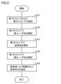
- Fig. 2 is a flowchart showing an optical measurement method according to an embodiment.
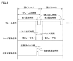
- Fig. 3 is a timing chart showing the timing of turning on the pulse laser of the optical measurement device 10 according to an embodiment.
- the optical measurement device 10 sets the first timing for irradiating the laser light from the laser source 1 and the second timing for irradiating the ultrasonic wave from the ultrasonic source 2 in the control unit 4a (step S101).
- the first timing is the timing for turning on the pulse laser to realize optical measurement by UOT within the decorrelation time with the camera 3 using the image sensor 3a.
- the first timing is the timing for irradiating the laser source 1 with two pulse laser lights of the first laser light and the second laser light at a time interval shorter than the time of one frame of the image sensor 3a at the timing of frame switching of the image sensor 3a.
- the first timing is such that the irradiation time of the first laser light and the irradiation time of the second laser light correspond to different exposure times of consecutive frames.
- the irradiation time of the first laser light corresponds to the exposure time of the first frame (first exposure time)
- the irradiation time of the second laser light corresponds to the exposure time of the second frame (second exposure time).
- the time for one frame of the image sensor 3a includes the exposure time and the readout time of the data captured during that exposure time.
- the period during which the frame signal is ON is the exposure time
- the period during which the frame signal is OFF is the readout time.
- the time interval during which the first laser light and the second laser light are irradiated is also called the pulse interval.
- This pulse interval need only be equal to or less than the decorrelation time. It is known that the decorrelation time is generally less than 1 ms, and it is preferable to find the average decorrelation time for multiple subjects and set the pulse interval to, for example, 500 ⁇ s or less.
- the control unit 4a controls the timing of laser light irradiation so that the timing of laser light irradiation corresponds to the exposure times of different frames, as described below. Specifically, the control unit 4a synchronizes the laser source 1, the ultrasonic source 2, and the camera 3 in advance with a signal (e.g., a synchronization signal) output from the signal generator 4b, and controls the laser source 1 to irradiate laser light at a timing corresponding to the exposure times of different frames.
- the control unit 4a may determine that the exposure times of the frames are different and control the timing of laser light irradiation. For example, the control unit 4a determines the exposure times of different frames using a signal for each frame (e.g., a trigger signal) output from the camera 3, and controls the timing of laser light irradiation.
- the period during which the first laser light and the second laser light are on (the period during which the laser drive signal is ON) is also called the pulse lighting time.
- the pulse lighting time By making the pulse lighting time shorter than the ultrasonic wave period (for example, 1/8 the ultrasonic wave period or less), the optical measurement device 10 can measure at a time width in which the speckle fluctuation caused by the ultrasonic wave can be considered to be stationary. Therefore, the optical measurement device 10 can obtain a direct difference value between a speckle pattern not modulated by ultrasonic waves and a speckle pattern modulated by ultrasonic waves in a certain state, enabling measurement with a high S/N ratio.
- the pulse lighting time is made shorter than the ultrasonic wave period, the amount of light that can be detected by the image sensor 3a decreases. In order to obtain an amount of light that can be detected by the image sensor 3a, it is preferable to configure the first laser light and the second laser light so that they include multiple pulsed laser lights.
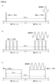
- FIG. 4 is a schematic diagram showing the lighting form of the pulsed laser of the optical measurement device 10 according to the embodiment.
- a first laser light including one pulsed laser light is irradiated in the first frame
- a second laser light including one pulsed laser light is irradiated in the second frame.
- the time interval (pulse interval) between the first laser light and the second laser light is 10 ⁇ s.
- the pulse lighting time of the first laser light and the second laser light is shorter than the period of the ultrasonic wave as shown in FIG. 4(a).
- the first laser light and the second laser light shown in FIG. 3 adopt the lighting form of the pulsed laser shown in FIG. 4(a), but the lighting forms of the pulsed laser shown in FIG. 4(b) and FIG. 4(c) described below may also be adopted.
- the first laser light including four pulsed laser lights is irradiated in the first frame
- the second laser light including four pulsed laser lights is irradiated in the second frame.
- the time interval (pulse interval) from the first pulsed laser light of the first laser light to the fourth pulsed laser light of the second laser light is 10 ⁇ s.
- the pulse lighting time of each of the first pulsed laser light and the second pulsed laser light is shorter than the period of the ultrasonic wave as shown in FIG. 4(b). However, since the total pulse lighting time of the four pulsed laser lights is four times the pulse lighting time of FIG. 4(a), the amount of light that can be detected by the image sensor 3a increases.
- the four pulsed laser lights are irradiated so as to be at the same peak position of each ultrasonic wave, a speckle pattern modulated by the part of the ultrasonic wave at the same peak position is obtained, and optical measurement that is not affected by the speckle pattern modulated by the part of the ultrasonic wave other than the peak is possible.
- the number of pulsed laser lights included in the first laser light and the second laser light is not limited to four, and may be more than one.
- the first laser light including one pulsed laser light is irradiated in the first frame
- the second laser light including one pulsed laser light is irradiated in the second frame.
- the time interval (pulse interval) between the first laser light and the second laser light is 10 ⁇ s.
- the pulsed lighting time of the first laser light and the second laser light is 4 ⁇ m, which corresponds to the length of four cycles of the ultrasonic wave, as shown in FIG. 4(c). Since the pulsed lighting time is four cycles of the ultrasonic wave, the amount of light that can be detected by the image sensor 3a increases.
- the speckle patterns modulated by four cycles of the ultrasonic wave are superimposed on the first laser light and the second laser light, the time average of the speckle patterns modulated by four cycles of the ultrasonic wave is obtained.
- the second timing is the timing at which the ultrasonic source 2 irradiates ultrasonic waves so that the ultrasonic waves reach the measurement position at the irradiation time of the second laser light.
- the second timing is the timing at which the ultrasonic source 2 irradiates the ultrasonic source 2 with pulsed ultrasonic waves before the ultrasonic delay time from the irradiation time of the second laser light.
- the ultrasonic delay time can be calculated from the distance from the ultrasonic source 2 to the measurement position.
- the ultrasonic waves irradiated by the ultrasonic source 2 are pulsed ultrasonic waves
- the period during which the ultrasonic waves are irradiated is also called the ultrasonic pulse width.
- the ultrasonic waves irradiated by the ultrasonic source 2 are not limited to pulsed ultrasonic waves, and may be continuous ultrasonic waves.
- FIG. 3 describes irradiating ultrasonic waves in accordance with the time when the second laser light irradiates the measurement position
- ultrasonic waves may be irradiated in accordance with the time when the first laser light irradiates the measurement position.
- the second timing is the timing at which the ultrasonic source 2 irradiates ultrasonic waves so that the ultrasonic waves reach the measurement position at the irradiation time of the first laser light.
- the ultrasonic source 2 may irradiate ultrasonic waves so that the ultrasonic waves reach the measurement position in accordance with either the irradiation time of the first laser light or the irradiation time of the second laser light.
- the optical measurement device 10 supplies a laser drive signal from the signal generator 4b to the laser source 1 based on the first timing set by the control unit 4a, causing the laser source 1 to irradiate the first laser light (step S102).
- the optical measurement device 10 supplies an ultrasonic drive signal from the signal generator 4b to the ultrasonic source 2 based on the second timing set by the control unit 4a, causing the ultrasonic source 2 to emit ultrasonic waves (step S103).
- the optical measurement device 10 supplies a laser drive signal from the signal generator 4b to the laser source 1 based on the first timing set by the control unit 4a, causing the laser source 1 to irradiate the second laser light (step S104).
- the optical measurement device 10 uses the data analysis unit 5 to extract signal components modulated by ultrasonic waves from the speckle patterns of the two detected frames (step S105).
- the data analysis unit 5 obtains a first speckle pattern that is not modulated by ultrasonic waves from the detection signal of the first laser light, and obtains a second speckle pattern modulated by ultrasonic waves from the detection signal of the second laser light.
- the data analysis unit 5 can extract a signal component (speckle pattern) with a high S/N ratio by determining the difference value between the first speckle pattern and the second speckle pattern.
- the time of one frame of the image sensor 3a shown in FIG. 3 includes an exposure time and a read time of data captured during the exposure time.
- the configuration of one frame of the image sensor varies depending on the type of sensor and the read method, and is not limited to the configuration shown in FIG. 3.
- FIG. 5 is a timing chart showing another lighting timing of the pulse laser of the optical measurement device 10 according to the embodiment.
- the time of one frame of the image sensor shown in FIG. 5 includes an exposure time and a read time of data captured in a frame prior to the exposure time. In the image sensor shown in FIG. 5, data captured during the first exposure time of the first frame is read out during the read time of the second frame. Therefore, in the second frame, the second exposure time of the second frame and the read time for reading the data of the first frame are performed in the same time zone.
- the first exposure time during which the first laser beam is irradiated and the second exposure time during which the second laser beam is irradiated are exposure times of different frames.
- the first exposure time is the exposure time of the first frame
- the second exposure time is the exposure time of the second frame.
- the period during which the exposure signal is ON is the exposure time
- the period during which the readout signal is ON is the readout time.
- the pulse interval is equal to or shorter than the decorrelation time
- the pulse illumination time is shorter than the ultrasonic period.
- the optical measurement device 10 can be applied to a measurement device for measuring brain function, and can measure the brain activity of a subject in a minimally invasive manner by near-infrared spectroscopy.
- a laser source 1, an ultrasound source 2, and a camera 3 shown in FIG. 1 are arranged on the surface of the subject's head.
- the living body 20 shown in FIG. 1 is the surface of the subject's head. This allows the optical measurement device 10 to measure the brain activity of the subject in a minimally invasive manner, and the activity state near the brain surface can be visualized in real time by functional near-infrared spectroscopy (fNIRS).
- fNIRS functional near-infrared spectroscopy
- Laser source 1 is configured to irradiate the first and second laser lights shown in FIG. 3 from the surface of the subject's head to the measurement position.
- Laser source 1 includes, for example, a semiconductor laser, and is configured to be able to irradiate laser lights of multiple wavelengths (for example, light of three wavelengths of 780 nm, 805 nm, and 830 nm) in the near-infrared wavelength range that has high biological permeability.
- Camera 3 includes an image sensor such as a CCD sensor, and detects the laser light from the measurement position. Camera 3 outputs an electrical signal according to the detected light.
- Ultrasound source 2 irradiates ultrasound to the measurement position on the subject's head.
- the data analysis unit 5 analyzes the change in the amount of hemoglobin (oxygenated hemoglobin, deoxygenated hemoglobin, and total hemoglobin) associated with brain activity based on the speckle pattern measured by the camera 3. This enables the optical measurement device 10 to minimally acquire the change in the amount of hemoglobin associated with brain activity, i.e., the change in blood flow and the activation state of oxygen metabolism.
- the device When the optical measurement device 10 is applied to a measurement system for measuring brain functions, the device may be configured to irradiate the subject's head with measurement light from a plurality of measurement probes arranged on the subject's head and receive the measurement light scattered in the brain of the subject's head.
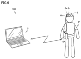
- Fig. 6 is a schematic diagram of a measurement system 100 of a modified example using the optical measurement device according to the embodiment.
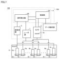
- Fig. 7 is a block diagram of the measurement system 100 of the modified example.
- the measurement system 100 for measuring brain function can measure brain activity of a subject P in a minimally invasive manner, and is configured as a brain function imaging device that visualizes the activity state near the brain surface in real time using functional near-infrared spectroscopy.
- the measurement system 100 is also configured, for example, from a main unit 10A that is attached to the subject P, and a data analysis section 5 that is a computer that receives and analyzes the data measured by the main unit 10A via wireless communication.
- the subject P is not constrained to the vicinity of the data analysis section 5 even during brain function measurement, and the subject P can move freely while carrying the main unit 10A, making it possible to perform brain function measurement in an environment closer to everyday life.
- the main unit 10A is composed of a laser source 1, an ultrasound source 2, a camera 3, and a control circuit 4.
- the measurement system 100 also includes a holder 6 that is attached to the head of the subject P and includes a plurality of attachment portions 61 for attaching a light-transmitting probe 6a, a light-receiving probe 6b, and an ultrasound probe 6c.
- the light-transmitting probe 6a, the light-receiving probe 6b, and the ultrasound probe 6c are each attached to the holder 6 attached to the head of the subject P, and thereby positioned on the surface of the subject P's head.
- the light-transmitting probe 6a is connected to the laser source 1 via an optical fiber, and irradiates the first laser light and the second laser light shown in FIG. 3 from the surface of the subject P's head to the measurement position.
- the light-receiving probe 6b is connected to the camera 3 via an optical fiber, and detects the laser light from the measurement position.
- the ultrasound probe 6c is connected to the ultrasound source 2 via wiring, and irradiates ultrasound from the surface of the subject P's head to the measurement position.
- the laser source 1 is configured to irradiate the first and second laser lights from the light-transmitting probe 6a to the head of the subject P via an optical fiber.
- the laser source 1 includes, for example, a semiconductor laser, and is configured to be able to irradiate laser lights of multiple wavelengths in the near-infrared wavelength range that has high biological permeability.
- the camera 3 includes an image sensor such as a CCD sensor, and is configured to acquire and detect the light that is incident on the light-receiving probe 6b via an optical fiber. The camera 3 outputs an electrical signal according to the detected light.
- the ultrasound source 2 irradiates ultrasound from the ultrasound probe 6c to a measurement position on the head of the subject P.
- the data analysis unit 5 is configured to analyze the change in hemoglobin amount associated with brain activity based on the speckle pattern measured by the camera 3. This enables the measurement system 100 to minimally acquire the change in hemoglobin amount associated with brain activity, i.e., the change in blood flow and the activation state of oxygen metabolism.
- the measurement system 100 is also configured to measure brain activity and acquire a two-dimensional distribution at each measurement point (measurement channel) formed by the light-transmitting probe 6a, light-receiving probe 6b, and ultrasound probe 6c.
- the ultrasonic probe 6c may further be an ultrasonic phased array, enabling ultrasonic steering and scanning.
- a bundle fiber may be used as the optical fiber for receiving light that connects the light receiving probe 6b and the camera 3.
- An optical measurement device includes a light source for irradiating a pulsed laser light into a living body, an ultrasound source for irradiating an ultrasound wave to a measurement position at a predetermined depth in the living body, an image sensor for detecting the laser light that has passed through a region in the living body including the measurement position, a control circuit for controlling the irradiation timing of the laser light from the light source, and an arithmetic circuit for extracting a signal component modulated by the ultrasound wave from the laser light detected by the image sensor.
- the control circuit irradiates a first laser light and a second laser light at a time interval shorter than the time of one frame of the image sensor, and controls the irradiation timing so that the irradiation time of the first laser light and the irradiation time of the second laser light correspond to different exposure times of consecutive frames, respectively.
- the ultrasound source irradiates ultrasound so that the ultrasound reaches the measurement position at the irradiation time of the first laser light or the second laser light.
- the arithmetic circuit extracts the signal component modulated by the ultrasound wave based on the detection signal of the first laser light and the detection signal of the second laser light detected by the image sensor.
- the first laser light and the second laser light are irradiated at a time interval shorter than the time of one frame of the image sensor, and the first exposure time for irradiating the first laser light and the second exposure time for irradiating the second laser light are different exposure times for consecutive frames, so that it is possible to complete measurement by the image sensor within the decorrelation time, reducing the effects of decorrelation and improving measurement accuracy.
- multiple pulsed laser beams are irradiated onto the measurement position, so the amount of laser beam detected by the image sensor can be increased.
- a pulse illumination time of the first laser light and the second laser light is shorter than a period of the ultrasonic wave.
- the speckle fluctuations caused by the ultrasonic waves can be considered to be stationary.
- the light source can irradiate laser light having different peak wavelengths.
- the light source can emit laser light with different peak wavelengths, making it possible to perform various measurements such as blood oxygen saturation.
- the ultrasonic source can irradiate a pulsed ultrasonic wave.
- the ultrasonic source irradiates pulsed ultrasonic waves, thereby reducing speckle fluctuations caused by ultrasonic waves.
- the ultrasonic source irradiates ultrasonic waves so that the ultrasonic waves are converged at the measurement position.
- the ultrasonic source irradiates ultrasonic waves so that the ultrasonic waves converge at the measurement position, thereby reducing speckle fluctuations caused by ultrasonic waves at positions other than the measurement position.
- a time interval for irradiating the first laser light and the second laser light is 500 ⁇ s or less.
- the light source irradiates laser light of multiple wavelengths in the near-infrared wavelength region, making it possible to measure oxygen saturation in the blood.
- An optical measurement method is an optical measurement method in an optical measurement device including a light source for irradiating a pulsed laser light into a living body, an ultrasound source for irradiating an ultrasound to a measurement position at a predetermined depth in the living body, an image sensor for detecting the laser light passing through a region in the living body including the measurement position, a control circuit for controlling the irradiation timing of the laser light from the light source, and an arithmetic circuit for extracting a signal component modulated by ultrasound from the laser light detected by the image sensor.
- the optical measurement method includes a step of irradiating a first laser light and a second laser light at a time interval shorter than the time of one frame of the image sensor, and controlling the irradiation timing so that the irradiation time of the first laser light and the irradiation time of the second laser light correspond to different exposure times of consecutive frames, a step of the ultrasound source irradiating ultrasound so that the ultrasound reaches the measurement position at the irradiation time of the first laser light or the second laser light, and a step of extracting the signal component modulated by ultrasound based on the detection signal of the first laser light and the detection signal of the second laser light detected by the image sensor.
- the first laser light and the second laser light are irradiated at a time interval shorter than the time of one frame of the image sensor, and the first exposure time for irradiating the first laser light and the second exposure time for irradiating the second laser light are different exposure times for consecutive frames, so that it is possible to complete measurement by the image sensor within the decorrelation time, reducing the effects of decorrelation and improving measurement accuracy.
Landscapes
- Health & Medical Sciences (AREA)
- Life Sciences & Earth Sciences (AREA)
- Pathology (AREA)
- General Health & Medical Sciences (AREA)
- Heart & Thoracic Surgery (AREA)
- Physics & Mathematics (AREA)
- Medical Informatics (AREA)
- Molecular Biology (AREA)
- Surgery (AREA)
- Animal Behavior & Ethology (AREA)
- Engineering & Computer Science (AREA)
- Public Health (AREA)
- Veterinary Medicine (AREA)
- Biomedical Technology (AREA)
- Chemical & Material Sciences (AREA)
- Analytical Chemistry (AREA)
- Biochemistry (AREA)
- General Physics & Mathematics (AREA)
- Immunology (AREA)
- Ultra Sonic Daignosis Equipment (AREA)
- Measurement Of The Respiration, Hearing Ability, Form, And Blood Characteristics Of Living Organisms (AREA)
- Measurement Of Mechanical Vibrations Or Ultrasonic Waves (AREA)
- Investigating Or Analyzing Materials By The Use Of Ultrasonic Waves (AREA)
Priority Applications (2)
| Application Number | Priority Date | Filing Date | Title |
|---|---|---|---|
| JP2025502705A JPWO2024176997A1 (enExample) | 2023-02-20 | 2024-02-19 | |
| CN202480012889.7A CN120693513A (zh) | 2023-02-20 | 2024-02-19 | 光测量装置及光测量方法 |
Applications Claiming Priority (2)
| Application Number | Priority Date | Filing Date | Title |
|---|---|---|---|
| JP2023024079 | 2023-02-20 | ||
| JP2023-024079 | 2023-02-20 |
Publications (1)
| Publication Number | Publication Date |
|---|---|
| WO2024176997A1 true WO2024176997A1 (ja) | 2024-08-29 |
Family
ID=92501155
Family Applications (1)
| Application Number | Title | Priority Date | Filing Date |
|---|---|---|---|
| PCT/JP2024/005689 Ceased WO2024176997A1 (ja) | 2023-02-20 | 2024-02-19 | 光計測装置、および光計測方法 |
Country Status (3)
| Country | Link |
|---|---|
| JP (1) | JPWO2024176997A1 (enExample) |
| CN (1) | CN120693513A (enExample) |
| WO (1) | WO2024176997A1 (enExample) |
Cited By (2)
| Publication number | Priority date | Publication date | Assignee | Title |
|---|---|---|---|---|
| WO2025100325A1 (ja) * | 2023-11-10 | 2025-05-15 | 株式会社島津製作所 | 光計測装置および解析方法 |
| WO2025100326A1 (ja) * | 2023-11-10 | 2025-05-15 | 株式会社島津製作所 | 光計測装置および解析方法 |
Citations (9)
| Publication number | Priority date | Publication date | Assignee | Title |
|---|---|---|---|---|
| WO2007035934A2 (en) * | 2005-09-22 | 2007-03-29 | Skyline Biomedical, Inc. | Apparatus and method for non-invasive and minimally-invasive sensing of parameters relating to blood |
| JP2009052915A (ja) * | 2007-08-23 | 2009-03-12 | Olympus Medical Systems Corp | 生体観測装置 |
| JP2012200478A (ja) * | 2011-03-28 | 2012-10-22 | Konica Minolta Medical & Graphic Inc | 超音波変調光計測装置および超音波変調光計測方法 |
| JP2016217860A (ja) * | 2015-05-20 | 2016-12-22 | キヤノン株式会社 | 制御装置、測定装置、制御方法、プログラム、記憶媒体 |
| JP2018008040A (ja) * | 2016-07-05 | 2018-01-18 | キヤノン株式会社 | 波面制御装置、波面制御方法、情報取得装置、プログラム、および、記憶媒体 |
| WO2018212115A1 (ja) * | 2017-05-15 | 2018-11-22 | 公立大学法人大阪市立大学 | 組織の粘弾性を断層可視化する装置および方法 |
| US20190083049A1 (en) * | 2017-09-18 | 2019-03-21 | The Charles Stark Draper Laboratory, Inc. | Massively Multi-Frequency Ultrasound-Encoded Tomography |
| US20190150743A1 (en) * | 2017-11-22 | 2019-05-23 | Hi Llc | Pulsed ultrasound modulated optical tomography using lock-in camera |
| US20190269331A1 (en) * | 2018-03-02 | 2019-09-05 | Hi Llc | Ultrasound modulating optical tomography using reduced laser pulse duration |
-
2024
- 2024-02-19 JP JP2025502705A patent/JPWO2024176997A1/ja active Pending
- 2024-02-19 CN CN202480012889.7A patent/CN120693513A/zh active Pending
- 2024-02-19 WO PCT/JP2024/005689 patent/WO2024176997A1/ja not_active Ceased
Patent Citations (9)
| Publication number | Priority date | Publication date | Assignee | Title |
|---|---|---|---|---|
| WO2007035934A2 (en) * | 2005-09-22 | 2007-03-29 | Skyline Biomedical, Inc. | Apparatus and method for non-invasive and minimally-invasive sensing of parameters relating to blood |
| JP2009052915A (ja) * | 2007-08-23 | 2009-03-12 | Olympus Medical Systems Corp | 生体観測装置 |
| JP2012200478A (ja) * | 2011-03-28 | 2012-10-22 | Konica Minolta Medical & Graphic Inc | 超音波変調光計測装置および超音波変調光計測方法 |
| JP2016217860A (ja) * | 2015-05-20 | 2016-12-22 | キヤノン株式会社 | 制御装置、測定装置、制御方法、プログラム、記憶媒体 |
| JP2018008040A (ja) * | 2016-07-05 | 2018-01-18 | キヤノン株式会社 | 波面制御装置、波面制御方法、情報取得装置、プログラム、および、記憶媒体 |
| WO2018212115A1 (ja) * | 2017-05-15 | 2018-11-22 | 公立大学法人大阪市立大学 | 組織の粘弾性を断層可視化する装置および方法 |
| US20190083049A1 (en) * | 2017-09-18 | 2019-03-21 | The Charles Stark Draper Laboratory, Inc. | Massively Multi-Frequency Ultrasound-Encoded Tomography |
| US20190150743A1 (en) * | 2017-11-22 | 2019-05-23 | Hi Llc | Pulsed ultrasound modulated optical tomography using lock-in camera |
| US20190269331A1 (en) * | 2018-03-02 | 2019-09-05 | Hi Llc | Ultrasound modulating optical tomography using reduced laser pulse duration |
Non-Patent Citations (4)
| Title |
|---|
| "Ultrasound-mediated optical tomography: a review of current methods", INTERFACE FOCUS, vol. 1, 2 June 2011 (2011-06-02), pages 632 - 648, XP055482557, DOI: 10.1098/rsfs.2011.0021 * |
| HISAKA, MASAKI: "Ultrasound-Modulated Optical Speckle Measurement for Biological Tissues", KOGAKU - JAPANESE JOURNAL OF OPTICS, OYO BUTSURI GAKKAI. KOGAKU KONWAKAI, TOKYO, JP, vol. 38, no. 6, 1 June 2009 (2009-06-01), JP , pages 310 - 315, XP009556928, ISSN: 0389-6625 * |
| LI RUI, DANIEL S ELSON, CHRIS DUNSBY, ROBERT ECKERSLEY, MENG-XING TANG: "Effects of acoustic radiation force and shear waves for absorption and stiffness sensing in ultrasound modulated optical tomography", OPTICS EXPRESS, vol. 19, no. 8, 11 April 2011 (2011-04-11), pages 7299 - 7311, XP093202646, DOI: 10.1364/OE.19.007299 * |
| MASAKI HISAKA, SHOHEI MATSUDA: "Locally Ultrasound-Modulated Optical Speckle Measurement for Scattering Medium", KOGAKU - JAPANESE JOURNAL OF OPTICS, OYO BUTSURI GAKKAI. KOGAKU KONWAKAI, TOKYO, JP, vol. 34, no. 12, 1 December 2005 (2005-12-01), JP , pages 660 - 668, XP009556929, ISSN: 0389-6625 * |
Cited By (2)
| Publication number | Priority date | Publication date | Assignee | Title |
|---|---|---|---|---|
| WO2025100325A1 (ja) * | 2023-11-10 | 2025-05-15 | 株式会社島津製作所 | 光計測装置および解析方法 |
| WO2025100326A1 (ja) * | 2023-11-10 | 2025-05-15 | 株式会社島津製作所 | 光計測装置および解析方法 |
Also Published As
| Publication number | Publication date |
|---|---|
| CN120693513A (zh) | 2025-09-23 |
| JPWO2024176997A1 (enExample) | 2024-08-29 |
Similar Documents
| Publication | Publication Date | Title |
|---|---|---|
| CN101385638B (zh) | 测量装置 | |
| EP0904011B1 (en) | Apparatus for imaging microvascular blood flow | |
| KR101336048B1 (ko) | 광 단층촬영의 촬상방법 및 그 장치 | |
| US7496395B2 (en) | Laser doppler perfusion imaging with a plurality of beams | |
| US8289502B2 (en) | Measurement apparatus and measurement method | |
| JP4739363B2 (ja) | 生体情報イメージング装置、生体情報の解析方法、及び生体情報のイメージング方法 | |
| JP4167144B2 (ja) | 散乱吸収体計測装置 | |
| US7144370B2 (en) | Method and apparatus for imaging of tissue using multi-wavelength ultrasonic tagging of light | |
| JP6146955B2 (ja) | 装置、表示制御方法、及びプログラム | |
| WO2024176997A1 (ja) | 光計測装置、および光計測方法 | |
| US11022540B2 (en) | Camera-based photoacoustic remote sensing (C-PARS) | |
| JP2005114473A (ja) | 光検出方法及び生体光計測装置 | |
| CN103169480B (zh) | 基于单光子计数器的近红外三维动态成像仪系统 | |
| JP2017187471A (ja) | 撮像装置 | |
| US20190142277A1 (en) | Photoacoustic apparatus and object information acquiring method | |
| JP6461288B2 (ja) | 生体情報イメージング装置、生体情報の解析方法、及び生体情報のイメージング方法 | |
| JP2007020735A (ja) | 生体光計測装置 | |
| KR102859405B1 (ko) | 다층 및 다중모드 광학 영상 장치 및 분석 방법 | |
| JP4647449B2 (ja) | 試料分析装置 | |
| WO2025100325A1 (ja) | 光計測装置および解析方法 | |
| WO2025100326A1 (ja) | 光計測装置および解析方法 | |
| US20130116553A1 (en) | Biological measuring apparatus and biological measuring method | |
| CN119924830B (zh) | 一种用于监测血氧饱和度和血流速度的一体化成像装置及方法 | |
| JP2010017375A (ja) | 超音波変調光断層画像化装置、およびそれを用いた超音波変調光断層画像化方法 | |
| JP6501820B2 (ja) | 処理装置、処理方法、及びプログラム |
Legal Events
| Date | Code | Title | Description |
|---|---|---|---|
| 121 | Ep: the epo has been informed by wipo that ep was designated in this application |
Ref document number: 24760296 Country of ref document: EP Kind code of ref document: A1 |
|
| ENP | Entry into the national phase |
Ref document number: 2025502705 Country of ref document: JP Kind code of ref document: A |
|
| WWE | Wipo information: entry into national phase |
Ref document number: 2025502705 Country of ref document: JP |
|
| WWE | Wipo information: entry into national phase |
Ref document number: 202480012889.7 Country of ref document: CN |
|
| NENP | Non-entry into the national phase |
Ref country code: DE |
|
| WWP | Wipo information: published in national office |
Ref document number: 202480012889.7 Country of ref document: CN |