WO2024176753A1 - インクジェットインク及び印刷物製造方法 - Google Patents
インクジェットインク及び印刷物製造方法 Download PDFInfo
- Publication number
- WO2024176753A1 WO2024176753A1 PCT/JP2024/002971 JP2024002971W WO2024176753A1 WO 2024176753 A1 WO2024176753 A1 WO 2024176753A1 JP 2024002971 W JP2024002971 W JP 2024002971W WO 2024176753 A1 WO2024176753 A1 WO 2024176753A1
- Authority
- WO
- WIPO (PCT)
- Prior art keywords
- ink
- inkjet
- gas barrier
- layered compound
- examples
- Prior art date
- Legal status (The legal status is an assumption and is not a legal conclusion. Google has not performed a legal analysis and makes no representation as to the accuracy of the status listed.)
- Ceased
Links
Images



Classifications
-
- B—PERFORMING OPERATIONS; TRANSPORTING
- B41—PRINTING; LINING MACHINES; TYPEWRITERS; STAMPS
- B41J—TYPEWRITERS; SELECTIVE PRINTING MECHANISMS, i.e. MECHANISMS PRINTING OTHERWISE THAN FROM A FORME; CORRECTION OF TYPOGRAPHICAL ERRORS
- B41J2/00—Typewriters or selective printing mechanisms characterised by the printing or marking process for which they are designed
- B41J2/005—Typewriters or selective printing mechanisms characterised by the printing or marking process for which they are designed characterised by bringing liquid or particles selectively into contact with a printing material
- B41J2/01—Ink jet
-
- C—CHEMISTRY; METALLURGY
- C09—DYES; PAINTS; POLISHES; NATURAL RESINS; ADHESIVES; COMPOSITIONS NOT OTHERWISE PROVIDED FOR; APPLICATIONS OF MATERIALS NOT OTHERWISE PROVIDED FOR
- C09D—COATING COMPOSITIONS, e.g. PAINTS, VARNISHES OR LACQUERS; FILLING PASTES; CHEMICAL PAINT OR INK REMOVERS; INKS; CORRECTING FLUIDS; WOODSTAINS; PASTES OR SOLIDS FOR COLOURING OR PRINTING; USE OF MATERIALS THEREFOR
- C09D11/00—Inks
- C09D11/30—Inkjet printing inks
Definitions
- the present invention relates to an ink-jet ink and a method for producing a printed product. More specifically, the present invention relates to an inkjet ink that provides good productivity for forming a coating film having gas barrier properties, and a method for producing a printed matter using the inkjet ink.
- Packaging materials used for food, medicines, precision equipment, etc. are required to have gas barrier properties that block gases such as oxygen and water vapor in order to protect the contents.
- Materials that have traditionally been used to impart gas barrier properties to packaging materials include aluminum, polyvinylidene chloride, and polyvinyl alcohol.
- Cellulose nanofibers have also been attracting attention as a new material for imparting gas barrier properties to packaging materials.
- the cellulose that constitutes cellulose nanofibers accounts for approximately half of the biomass materials produced on Earth.
- cellulose nanofibers also have excellent physical properties such as strength, elastic modulus, dimensional stability, heat resistance, and crystallinity. For this reason, cellulose nanofibers are expected to be used in functional materials.
- Non-Patent Document 1 reports that by producing a coating film that combines this cellulose nanofiber with an inorganic layered mineral, a higher oxygen gas barrier property is achieved.
- Patent Documents 1 and 2 disclose techniques that enable further improvement of the barrier property and improvement of the moisture resistance of the coating film. In these techniques, in addition to cellulose nanofibers and inorganic layered minerals, water-soluble polymers, sizing agents, crosslinking agents, and auxiliary agents are used in the coating liquid for forming the gas barrier film.
- these conventional coating fluids for forming gas barrier films were designed for application using a bar coater method, a gravure coater method, etc. These coating methods require plate changes every time the amount of coating is changed for various substrates.
- these coating methods require the packaging material to have a laminated structure when functions other than gas barrier properties are to be imparted to the packaging material. Therefore, when conventional coating fluids for forming gas barrier films are used, there is a problem that the production process for packaging materials with gas barrier films becomes complicated and productivity is low.
- the coating fluids for forming other functional films may affect the gas barrier properties.
- the present invention was made in consideration of the above problems and circumstances, and the problem to be solved is to provide an inkjet ink that has good productivity for producing a coating film with gas barrier properties, and a method for producing printed matter using the inkjet ink.
- the inventors have investigated the causes of the above problems. As a result, the inventors have found that the above problems can be solved by limiting the lower limit of the total content of cellulose nanofiber and layered compound, and the upper limit of the viscosity of the ink. Based on this, the inventors have arrived at the present invention.
- the above problems are solved by the following means.
- An inkjet ink for forming a coating on a substrate comprising: For forming gas barrier films, Contains cellulose nanofibers and a layered compound, The total content of the cellulose nanofibers and the layered compound is 1% by mass or more, An ink-jet ink having a viscosity of 100 mPa ⁇ s or less at 25° C. at a shear rate of 1000 (1/S).
- a method for producing a printed matter using an inkjet ink comprising the steps of: 5.
- a method for producing a printed matter comprising a step of ejecting the ink-jet ink according to any one of claims 1 to 4 onto a substrate by an ink-jet system to form a coating film.
- the above-mentioned means of the present invention can provide an inkjet ink that has good productivity for producing a coating film with gas barrier properties, and a method for producing printed matter using the inkjet ink.
- the present invention provides a composition (inkjet ink) that can impart gas barrier properties to a substrate and is suitable for application by an inkjet method.
- the inkjet ink of the present invention contains both cellulose nanofibers and a layered compound in a total content of 1% by mass or more.
- the inkjet ink of the present invention can impart high gas barrier properties to a substrate with a relatively small amount of application. A small amount of application leads to a reduction in the drying load and a shortened drying process.
- the inkjet ink of the present invention has a viscosity of 100 mPa ⁇ s or less at 25°C at a shear rate of 1000 (1/S).
- the inkjet ink of the present invention allows the inkjet ink of the present invention to be applied by an inkjet method. If the viscosity under these conditions exceeds 100 mPa ⁇ s, the inkjet ink is poorly ejected by the inkjet method and cannot be applied.
- coating can be performed using the inkjet method, there is no need for plate changing operations, which are required with conventional coating methods.
- patterning using the inkjet method can impart gas barrier properties and other functions to the same surface of the substrate, reducing the number of layers of packaging material. This can improve the productivity of printed materials such as coating films with gas barrier properties and packaging materials that have such coating films.
- FIG. 1 is a schematic diagram showing the main components of an inkjet image forming apparatus equipped with an example of an inkjet head suitable for the ink of the present invention.
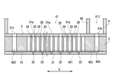
- FIG. 2 is an enlarged cross-sectional view of a head chip of the inkjet head shown in FIG. 1 .
- FIG. 2 is a plan view of a nozzle plate of the inkjet head shown in FIG. 1; Schematic diagram of the layer structure of conventional packaging materials Schematic diagram of the layer structure of a packaging material produced using the ink of the present invention.
- the inkjet ink of the present invention is an inkjet ink for forming a coating film on a substrate, is for forming a gas barrier film, contains cellulose nanofibers and a layered compound, the total content of the cellulose nanofibers and the layered compound is 1 mass% or more, and has a viscosity of 100 mPa ⁇ s or less at 25°C at a shear rate of 1000 (1/S).
- This characteristic is a technical characteristic common to or corresponding to the following embodiments.
- the ink contains a hydrophilic organic solvent having a boiling point of 200°C or less in the range of 5 to 30% by mass.
- the hydrophilic organic solvent contributes to adjusting the viscosity of the ink and preventing the nozzle surface from drying out during inkjet ejection.
- the hydrophilic organic solvent is less likely to remain in the coating film and is less likely to impair the gas barrier properties of the coating film.
- the ink drying conditions to prevent the hydrophilic organic solvent from remaining can be less strict.
- the ink contains a neutralizing agent and has a pH value at 25°C within the range of 5 to 10.
- the inkjet ink of the present invention it is preferable to contain a dispersant for the layered compound. This increases the dispersion stability of the layered compound in water, and increases the density of the gas barrier film. This further improves the gas barrier properties of the gas barrier film.
- the method for producing a printed matter of the present invention is a method for producing a printed matter using an inkjet ink, and includes a step of ejecting the inkjet ink of the present invention onto a substrate using an inkjet method to form a coating film.
- the inkjet method it is preferable to constantly vibrate the meniscus of the nozzle at 1 kHz or more. This makes it easier to form a coating film with small variations in gas barrier properties.
- the inkjet ink of the present invention is an inkjet ink for forming a coating film on a substrate, for forming a gas barrier film, containing cellulose nanofibers and a layered compound, the total content of the cellulose nanofibers and the layered compound being 1 mass % or more, and having a viscosity of 100 mPa s or less at 25°C at a shear rate of 1000 (1/S).
- inkjet ink will simply be referred to as "ink.”
- the ink of the present invention is for forming a gas barrier film.
- "For forming a gas barrier film” means that the application is to form a coating film with gas barrier properties.
- Gas barrier film and “coating film with gas barrier properties” refer to a film that can improve the gas barrier properties of a substrate having the film. Gas barrier properties can be evaluated, for example, by oxygen permeability [cm3/(m2 ⁇ day ⁇ atm)].
- the ink of the present invention contains both cellulose nanofibers and a layered compound. This allows it to exhibit higher gas barrier properties than if each of them was contained alone.
- the content ratio of cellulose nanofiber to layered compound in the ink can be selected according to the viscosity and thixotropy of the ink, and the required gas barrier properties.
- the content ratio, in terms of "mass of cellulose nanofiber: mass of layered compound”, is preferably within the range of 1:100 to 100:1, more preferably within the range of 1:10 to 10:1, and even more preferably within the range of 1:5 to 5:1.
- Ink containing cellulose nanofibers and a layered compound has thixotropy, which means that the viscosity decreases when a shear force is applied.
- thixotropy By controlling this thixotropy, the ejection performance of the ink can be suitably controlled.
- a shear force is applied to the ink when the ink is ejected.
- the viscosity when a high shear force is applied is particularly important.
- the ink of the present invention has a viscosity of 100 mPa ⁇ s or less at 25°C at a shear rate of 1000 (1/s). This allows the inkjet ink of the present invention to be applied by the inkjet method. If the viscosity exceeds 100 mPa ⁇ s, the inkjet ink cannot be applied because of poor ejection properties in the inkjet method. From the viewpoint of ejection properties, the viscosity of the ink under these conditions is preferably 50 mPa ⁇ s or less, and more preferably 25 mPa ⁇ s or less. There is no particular limit to the lower limit of the viscosity of the ink under these conditions, but from the viewpoint of ejection properties, 5 mPa ⁇ s or more is preferable.
- the ink of the present invention contains cellulose nanofibers.
- Cellulose nanofibers are cellulose that has been made into nanofibers.
- known cellulose nanofibers can be used.
- Cellulose nanofibers are generally produced by mechanical treatment of unmodified cellulose, chemical modification treatment, or biological synthesis with enzyme modification. Cellulose nanofibers produced by any method can be suitably used in the present invention.
- Unmodified cellulose nanofibers produced by mechanical processing without modification are also called unmodified cellulose nanofibers.
- Unmodified cellulose nanofibers are unmodified cellulose fibers that have been mechanically defibrated. Examples of defibration methods include the high-pressure homogenizer method (Gaulin method), the microfluidizer method (opposed jet collision method), the grinder method using abrasive stones, the ball mill crushing method, and the underwater counter collision method (ACC method).
- Chemically modified cellulose nanofibers produced by chemical modification treatment are also called chemically modified cellulose nanofibers.
- Chemically modified cellulose nanofibers are cellulose nanofibers in which a substituent has been introduced.
- Examples of chemically modified cellulose nanofibers include nanofibers in which the hydroxyl groups of cellulose have been carboxymethylated, nanofibers in which carboxyl groups have been introduced by oxidation using an N-oxy radical such as 2,2,6,6-tetramethyl-1-piperidine-N-oxyl (TEMPO) as a catalyst, nanofibers with phosphoric acid groups or substituents derived from phosphoric acid groups, nanofibers in which phosphorous acid ester groups have been introduced into some of the hydroxyl groups of cellulose fibers, and nanofibers obtained from xanthated cellulose.
- Chemically modified cellulose nanofibers in which carboxyl groups, phosphoric acid ester groups, or phosphorous acid ester groups have been introduced may be either metal salt type or acid type.
- Enzyme-modified cellulose nanofibers are cellulose nanofibers that have been treated with enzymes.
- Examples of enzyme-modified cellulose nanofibers include cellulose nanofibers that have been mechanically defibrated using cellulase enzymes. The treatment with enzymes may be carried out at any stage, before defibration, simultaneously with defibration, or after defibration.
- the cellulose nanofiber may be bacterial cellulose synthesized by microorganisms.
- the average fiber diameter of the cellulose nanofibers is 200 nm or less.
- the average fiber diameter of the cellulose nanofibers is preferably 1 to 200 nm, more preferably 1 to 100 nm, and even more preferably 1 to 50 nm.
- the average aspect ratio of cellulose nanofibers is preferably 10 to 2000, more preferably 10 to 500, and even more preferably 100 to 350. "Aspect ratio" is the value obtained by dividing the fiber length by the fiber diameter.
- Short-fiber cellulose nanofibers which have a fine fiber diameter and a small aspect ratio, have weaker hydrogen bonds between the fibers and can suppress increases in ink viscosity. Therefore, from the perspective of inkjet ejection stability, short-fiber cellulose nanofibers are preferred.
- cellulose nanofibers for example, the following can be suitably used.
- LeoCrysta (registered trademark) manufactured by Daiichi Kogyo Seiyaku Co., Ltd.
- Ciellenpia is a registered trademark
- AuroVisco manufactured by Oji Paper Co.
- XCNF registered trademark
- Stellafine registered trademark manufactured by Marusumi Paper Co., Ltd.
- Aronfibro T-OP 100 manufactured by Toagosei Co., Ltd. (“Aronfibro” is a registered trademark); Bacterial nanocellulose from Samsung Industries Co., Ltd.; Fibrima manufactured by Masuko Sangyo Co., Ltd.; Nanoforest manufactured by Chuetsu Pulp Industry Co., Ltd.; Cellulose nanofiber manufactured by Tarui Chemical Co., Ltd.
- the content of cellulose nanofiber in the ink is preferably 5% by mass or less, and more preferably 3% by mass or less.
- the content of cellulose nanofiber is preferably 0.25% by mass or more, and more preferably 0.5% by mass or more.
- Cellulose nanofibers are often produced as an aqueous dispersion due to the fiberization process from hydrophilic cellulose. Therefore, from the viewpoint of the ink preparation process, it is preferable to mix the aqueous dispersion of cellulose nanofibers with a layered compound to produce an aqueous inkjet ink. Dried cellulose nanofibers may also be redispersed in water for use.
- Cellulose nanofibers may be used in combination of two or more types.
- the ink-jet ink of the present invention contains a layered compound.
- nanosheets When layered compounds are used in coating fluids for forming gas barrier films, the layers peel off and are dispersed as nanosheets.
- the size, shape, and composition of nanosheets of layered compounds vary depending on the type of layered compound.
- the thickness of a typical nanosheet of a layered compound is about 1 nm.
- the average length in the longitudinal direction of the nanosheet varies depending on the place of origin and synthesis method of the layered compound.
- the average length in the longitudinal direction of nanosheets is generally, for example, 40 to 50 nm for synthetic smectite, 200 to 400 nm for natural montmorillonite, 0.1 to 10 ⁇ m for synthetic mica and hectorite, and several tens of ⁇ m for particularly large synthetic products of natural mica or hydrotalcite.
- Many nanosheets have a permanent charge, and in order to compensate for the charge, inorganic ions often exist between the layers of the nanosheet to maintain electrical neutrality.
- any layered compound that, when used in combination with cellulose nanofibers, provides a coating with gas barrier properties can be freely used.
- a crystalline inorganic compound having a layered structure can be used as the layered compound.
- An example of a layered compound is an inorganic layered compound.
- An inorganic layered compound is a layered material in which plate-shaped inorganic crystals are stacked.
- inorganic layered compounds include clay minerals such as talc, kaolinite, smectite, and mica.
- clay minerals include clay minerals such as kaolinite, montmorillonite, bentonite, saponite, hectorite, beidellite, stevensite, magadiite, ilealite, kanemite, nontronite, vermiculite, halloysite, tetrasilicic mica, and hydrotalcite.
- montmorillonite, mica, bentonite, beidellite, saponite, stevensite, and hectorite is preferred.
- Compounds other than clay minerals can also be used as inorganic layered compounds.
- inorganic layered compounds other than clay minerals include metal oxides having a layered structure, such as titanates, niobates, manganates, phosphates, tin oxide, cobalt oxide, copper oxide, iron oxide, nickel oxide, platinum oxide, ruthenium oxide, and rhodium oxide.
- Composite oxides of the component elements of the above-mentioned metal oxides can also be used as layered compounds other than clay minerals.
- Graphite can also be used as an inorganic layered compound other than clay minerals.
- the layered compounds may be natural or synthetic.
- the layered compounds may be used in combination of two or more types.
- the average length in the longitudinal direction of the nanosheet of the layered compound is preferably within the range of 10 to 2000 nm, and more preferably within the range of 10 to 500 nm. This makes it easier to achieve a balance between gas barrier properties, dispersion stability in the ink, dispersibility in the coating film, and prevention of clogging in the inkjet nozzle.
- the longer the nanosheet of the layered compound is in the longitudinal direction the longer the diffusion path of the gas when it permeates the coating film, so the higher the gas barrier properties tend to be.
- the longer the nanosheet of the layered compound is in the longitudinal direction the larger the surface area for interlayer interaction, making peeling and dispersion more difficult.
- the average length and average thickness of a nanosheet of a layered compound can be measured, for example, using an electron microscope or an atomic force microscope.
- the average thickness of a nanosheet of a layered compound is, for example, the average of 50 thicknesses measured at a specified cross section.
- the average length of a nanosheet of a layered compound is the average of 50 lengths measured as the maximum diameter when the nanosheet is viewed in a planar view.
- the aspect ratio of a nanosheet of a layered compound is calculated as the length divided by the thickness.
- the layered compounds may be, for example, Kunipia-F and Kunipia-G, which are refined natural bentonite, Sumecton-SA, which is a synthetic saponite, Sumecton-ST, which is a synthetic stevensite, Sumecton-SWN, which is a synthetic hectorite (all manufactured by Kunimine Industries Co., Ltd.), Laponite, which is a synthetic layered silicate (manufactured by Big-Chemie Co., Ltd.), synthetic mica PDM-5B (manufactured by Topy Industries Co., Ltd.), and Bengel, which is a refined natural bentonite (manufactured by Hoshun Yoko Co., Ltd.).
- Kunipia-F and Kunipia-G which are refined natural bentonite
- Sumecton-SA which is a synthetic saponite
- Sumecton-ST which is a synthetic stevensite
- the layered compounds may also be those obtained by complexing layered minerals with organic compounds.
- Examples of those obtained by complexing layered minerals with organic compounds include complexes in which quaternary ammonium ions having long-chain alkyl groups are intercalated between layers by ion exchange.
- Examples of commercially available products of such complexes include Benton 27 and Benton 38 (manufactured by Elementis Specialties Co., Ltd.).
- the content of the layered compound in the ink is preferably 5% by mass or less, and more preferably 3% by mass or less.
- the content of the layered compound is preferably 0.25% by mass or more, and more preferably 0.5% by mass or more.
- the ink-jet ink of the present invention is preferably an aqueous ink containing water as a dispersion medium.
- the water contained in the ink is not particularly limited, and can be, for example, ion-exchanged water, distilled water, or pure water.
- the amount of water contained in the ink is not particularly limited, and constitutes the balance of the other components.
- the ink-jet ink of the present invention preferably contains a hydrophilic organic solvent in order to adjust the viscosity of the ink and to prevent the nozzle surface from drying during ink-jet ejection.
- Hydrophilic organic solvents contained in the ink include, for example, alcohols, polyhydric alcohols, amines, amides, glycol ethers, and 1,2-alkanediols with 4 or more carbon atoms.
- alcohols examples include methanol, ethanol, 1-propanol, 2-propanol, 1-butanol, 2-butanol, 2-methyl-1-propanol, t-butanol, 3-methoxy-1-butanol, 3-methoxy-3-methylbutanol, 1-octanol, 2-octanol, n-nonyl alcohol, tridecyl alcohol, n-undecyl alcohol, stearyl alcohol, oleyl alcohol, and benzyl alcohol.
- polyhydric alcohols examples include ethylene glycol, diethylene glycol, triethylene glycol, tetraethylene glycol, polyethylene glycols with 5 or more ethylene oxide groups, propylene glycol, dipropylene glycol, tripropylene glycol, polypropylene glycols with 4 or more propylene oxide groups, butylene glycol, hexanediol, pentanediol, glycerin, hexanetriol, and thiodiglycol.
- amines include ethanolamine, diethanolamine, triethanolamine, N-methyldiethanolamine, N-ethyldiethanolamine, morpholine, N-ethylmorpholine, ethylenediamine, diethylenediamine, triethylenetetramine, tetraethylenepentamine, polyethyleneimine, pentamethyldiethylenetriamine, and tetramethylpropylenediamine.
- amides include formamide, N,N-dimethylformamide, and N,N-dimethylacetamide.
- glycol ethers examples include ethylene glycol monoethyl ether, ethylene glycol monobutyl ether, diethylene glycol monoethyl ether, diethylene glycol monobutyl ether, triethylene glycol monobutyl ether, propylene glycol monopropyl ether, dipropylene glycol monomethyl ether, and tripropylene glycol monomethyl ether.
- 1,2-alkanediols with 4 or more carbon atoms examples include 1,2-butanediol, 1,2-pentanediol, 1,2-hexanediol, and 1,2-heptanediol.
- Two or more hydrophilic organic solvents may be used in combination.
- the boiling point of the hydrophilic organic solvent is preferably 200°C or lower. If the organic solvent remains in the coating film, it becomes difficult to improve the gas barrier properties. A hydrophilic organic solvent with a boiling point of 200°C or lower is less likely to remain in the coating film. In addition, if the boiling point of the hydrophilic organic solvent is 200°C or lower, the ink drying conditions to prevent the hydrophilic organic solvent from remaining do not need to be strict.
- the content of the hydrophilic organic solvent in the ink is preferably 30% by mass or less, and more preferably 20% by mass or less.
- the content of the hydrophilic organic solvent in the ink is preferably 5% by mass or more.
- the inkjet ink of the present invention preferably contains a neutralizing agent as necessary.
- Layered compounds, particularly layered clay minerals, are often alkaline with a pH of about 10 to 11 due to their large surface charge. Therefore, inks containing layered compounds tend to have a high pH.
- the pH of the ink is not too high.
- the ink further contains a neutralizing agent, and the pH at 25° C. is preferably adjusted to within a range of 5 to 10, more preferably within a range of 6 to 9.
- the type of neutralizing agent is not particularly limited, but it is preferable to use an acidic neutralizing agent that is weakly acidic and easy to handle, such as citric acid.
- the neutralizing agent When the ink contains a neutralizing agent, the surface charge of the layered compound is neutralized, which may reduce the dispersibility of the layered compound. Therefore, it is preferable that the neutralizing agent also functions as a dispersant for the layered compound.
- acidic neutralizing agents that also function as dispersants for layered compounds include disodium dihydrogen pyrophosphate and disodium etidronate. It is also preferable to use a neutralizing agent in combination with a dispersant for layered compounds, which will be described later.
- the inkjet ink of the present invention preferably contains a dispersant for the layered compound as necessary.
- the dispersant for the layered compound enhances the dispersion stability of the layered compound in water, forms a dense gas barrier film, and contributes to improving the gas barrier properties.
- the dispersant for the layered compound is particularly useful when the ink contains a neutralizer.
- dispersants for layered compounds include phosphate-based dispersants and polycarboxylate-based dispersants.
- Phosphate-based dispersants are believed to be adsorbed to the particle side of layered compounds, and to increase the dispersion stability of layered compounds by electrostatic repulsion based on the negative charge of phosphate.
- Specific examples of phosphate-based dispersants include sodium orthophosphate, sodium pyrophosphate (sodium diphosphate), disodium dihydrogen pyrophosphate, tetrasodium etidronate, disodium etidronate, sodium tripolyphosphate (sodium triphosphate), sodium tetraphosphate, sodium hexametaphosphate, sodium polyphosphate, trisodium phosphate, and sodium dihydrogen phosphate.
- Preferred examples of phosphate-based dispersants include sodium pyrophosphate, disodium dihydrogen pyrophosphate, sodium tripolyphosphate, disodium etidronate, and sodium hexametaphosphate.
- Polycarboxylate-based dispersants are believed to increase the dispersion stability of layered compounds by adsorbing to the particle side of the layered compound and by electrostatic repulsion due to the negative charge of the polycarboxylate (carboxylate).
- Polycarboxylate-based dispersants are polymers of salts of cations, such as inorganic cations (metal cations) such as sodium or organic cations such as ammonium, and carboxylic acids.
- metal cations such as sodium or organic cations such as ammonium, and carboxylic acids.
- Examples of polycarboxylate-based dispersants include poly(meth)acrylates and poly(meth)acrylate/maleate copolymers.
- Examples of polycarboxylate-based dispersants include sodium polycarboxylate and ammonium polycarboxylate.
- sodium polycarboxylate examples include sodium poly(meth)acrylate and sodium (meth)acrylate/sodium maleate copolymers.
- ammonium polycarboxylate examples include ammonium poly(meth)acrylate and ammonium (meth)acrylate/ammonium maleate copolymers.
- the content of the phosphate-based dispersant in the ink is preferably within the range of 1 to 100 parts by mass, more preferably within the range of 10 to 60 parts by mass, and even more preferably within the range of 20 to 40 parts by mass, per 100 parts by mass of the layered compound.
- the content of the polycarboxylate dispersant in the ink is preferably within the range of 1 to 100 parts by mass, more preferably within the range of 10 to 60 parts by mass, and even more preferably within the range of 20 to 40 parts by mass, per 100 parts by mass of the layered compound.
- the dispersant content is mainly cellulose nanofiber, but also includes water-soluble resins such as polyvinyl alcohol and water-dispersible resins.
- the inkjet ink of the present invention preferably contains a dispersant for the cellulose nanofibers as necessary.
- a dispersant for the cellulose nanofibers a compound having a hydrophilic group can be used.
- the hydrophilic group include a hydroxy group, an amino group, a carboxy group, a sulfo group, and a phosphate group.
- the dispersant for cellulose nanofibers can be a monomer having a hydrophilic group or a surfactant.
- monomers having a hydrophilic group include propylene glycol and N-vinylacetamide.
- a surfactant is a compound that has a chemical structure in which a portion having a hydrophilic substituent and a portion having a hydrophobic substituent are covalently bonded.
- the ink-jet ink of the present invention preferably contains a surfactant as necessary, which makes it possible to improve the ejection stability of the ink and to control the spread (dot diameter) of the ink droplets that have landed on the substrate.
- Surfactants can be used without particular restrictions as long as they do not impair the effects of the present invention, but nonionic surfactants are preferred. This is because ionic surfactants interact with the permanent charge of the layered compound, making it difficult for them to exhibit surface activity.
- fluorine-based or silicone-based surfactants that have a high static surface tension reducing ability; anionic surfactants such as dioctyl sulfosuccinate that have a high dynamic surface tension reducing ability; and nonionic surfactants such as relatively low molecular weight polyoxyethylene alkyl ethers, polyoxyethylene alkyl phenyl ethers, acetylene glycols, Pluronic surfactants ("Pluronic" is a registered trademark), and sorbitan derivatives are preferably used. It is also preferable to use a fluorine-based or silicone-based surfactant in combination with a surfactant that has a high dynamic surface tension reducing ability.
- the silicone surfactant is preferably a polyether-modified polysiloxane compound.
- silicone surfactants include KF-351A and KF-642 manufactured by Shin-Etsu Chemical Co., Ltd., BYK345, BYK347 and BYK348 manufactured by BYK-Chemie, and TEGOWET250 manufactured by Evonik.
- a fluorosurfactant is a surfactant in which some or all of the hydrogen atoms bonded to the carbon of the hydrophobic group of a normal surfactant have been replaced with fluorine. Fluorine-based surfactants that have a perfluoroalkyl group in the molecule are preferred.
- fluorine-based surfactants include Megafac F manufactured by Dainippon Ink & Chemicals, Surflon manufactured by Asahi Glass, Fluorad FC manufactured by Minnesota Mining & Manufacturing Company, Monflor manufactured by Imperial Chemical Industries, Zonyls manufactured by E.I. duPont Nemelas & Company, and Licowet VPF manufactured by Parkwerke Hoechst.
- the amount of surfactant contained in the ink is not particularly limited, but is preferably within the range of 0.1 to 5.0% by mass.
- the inkjet ink of the present invention may further contain a resin other than the cellulose nanofiber in order to improve the gas barrier properties of the coating film and the fixation to the substrate.
- a resin other than the cellulose nanofiber is also referred to as "other resin”.
- the other resin include a water-soluble resin and a water-dispersible resin other than the cellulose nanofiber.
- the ink may contain one or more types of other resins.
- the ink preferably contains at least one polyvinyl alcohol resin selected from the group consisting of polyvinyl alcohol polymers and their derivatives as other resins.
- the saponification degree of the polyvinyl alcohol resin is preferably 95% or more.
- the polymerization degree of the polyvinyl alcohol resin is preferably 300 to 2400, more preferably 450 to 2000. The higher the saponification degree and polymerization degree of the polyvinyl alcohol resin, the lower the moisture absorption and swelling property. When the saponification degree of the polyvinyl alcohol resin is 95% or more, sufficient gas barrier properties are easily obtained. When the polymerization degree of the polyvinyl alcohol resin is 300 or more, the gas barrier properties and film cohesive strength are easily excellent.
- the polymerization degree of the polyvinyl alcohol resin is 2400 or less, the increase in the viscosity of the ink is suppressed, it is easy to mix uniformly with other components, and problems such as a decrease in gas barrier properties and adhesion strength are easily suppressed.
- the saponification degree and polymerization degree of the polyvinyl alcohol resin can be measured by the method described in JIS K 6726:1994.
- resins besides polyvinyl alcohol resin include polyester resin, polyurethane resin, polyacrylic resin, etc.
- the polyester resin can be obtained by using a polyhydric alcohol component and a polycarboxylic acid component.
- the polycarboxylic acid component can be a polycarboxylic acid, a polycarboxylic acid anhydride, a polycarboxylic acid ester, etc.
- Examples of the polyhydric alcohol component include dihydric alcohols (diols).
- Dihydric alcohols (diols) include alkylene glycols having 2 to 36 carbon atoms (ethylene glycol, 1,2-propylene glycol, 1,3-propylene glycol, 1,4-butylene glycol, 1,6-hexanediol, etc.), alkylene ether glycols having 4 to 36 carbon atoms (diethylene glycol, triethylene glycol, dipropylene glycol, polyethylene glycol, polypropylene glycol, polybutylene glycol, etc.), alicyclic diols having 6 to 36 carbon atoms (1,4-cyclohexanediol, etc.), and cyclohexanediols having 6 to 36 carbon atoms (1,4-cyclohexanediol, etc.).
- alkylene oxides ethylene oxide (hereinafter abbreviated as EO), propylene oxide (hereinafter abbreviated as PO), butylene oxide (hereinafter abbreviated as BO)) adducts of the alicyclic diols having 2 to 4 carbon atoms (addition moles in the range of 1 to 30), alkylene oxides (EO, PO, BO, etc.) adducts of bisphenols (bisphenol A, bisphenol F, bisphenol S, etc.) having 2 to 4 carbon atoms (addition moles in the range of 2 to 30), etc. These may be used alone or in combination of two or more.
- EO ethylene oxide
- PO propylene oxide
- BO butylene oxide
- Examples of the polyvalent carboxylic acid component include divalent carboxylic acids (dicarboxylic acids).
- Examples of divalent carboxylic acids (dicarboxylic acids) include alkane dicarboxylic acids having 4 to 36 carbon atoms (succinic acid, apidic acid, sebacic acid, etc.), alkenyl succinic acids (dodecenyl succinic acid, etc.), alicyclic dicarboxylic acids having 4 to 36 carbon atoms (dimerized linoleic acid, etc.), alkene dicarboxylic acids having 4 to 36 carbon atoms (maleic acid, fumaric acid, citraconic acid, mesaconic acid, etc.), aromatic dicarboxylic acids having 8 to 36 carbon atoms (phthalic acid, isophthalic acid, terephthalic acid or derivatives thereof, naphthalenedicarboxylic acid, etc.), etc. These may be used alone or in combination of two or more.
- the number average molecular weight of the polyester resin is preferably in the range of 1,000 to 50,000, and more preferably in the range of 2,000 to 20,000.
- polyester resin a commercially available product may be used.
- a commercially available product for example, a dispersion in which a polyester resin is dispersed in an aqueous solvent may be used.
- polyester resin dispersions include the following. In the examples, the number average molecular weight of the polyester resin contained in the product (dispersion) is shown in parentheses. These may be used alone or in combination of two or more types.
- polyester resin dispersions include Elitel KA-5034 (Unitika Ltd., number average molecular weight: 8500), Elitel KA-5071S (Unitika Ltd., number average molecular weight: 8500), Elitel KA-1449 (Unitika Ltd., number average molecular weight: 7000), Elitel KA-0134 (Unitika Ltd., number average molecular weight: 8500), Elitel KA-3556 (Unitika Ltd., number average molecular weight: 8000), Elitel KA-6137 (Unitika Ltd., number average molecular weight: 5000), Elitel KZA-6034 (Unitika Ltd., number average molecular weight: 6 500), Elitel KT-8803 (manufactured by Unitika Ltd., number average molecular weight: 15,000), Elitel KT-8701 (manufactured by Unitika Ltd., number average molecular weight: 13,000), Elitel KT-9204 (manufactured by Unitika Ltd., number average molecular weight:
- hydrophilic group examples include a carboxy group (-COOH) and its salts, a sulfonic acid group (-SO3H) and its salts, etc.
- the salts include alkali metal salts and amine salts.
- the alkali metal salts include sodium salts and potassium salts.
- a carboxy group or a salt thereof is preferable.
- the polyurethane resin is preferably a dispersion in which a self-emulsifying polyurethane having water-soluble functional groups in its molecules is dispersed in an aqueous solvent, or a dispersion in which a forced-emulsifying polyurethane emulsified under strong mechanical shear force in combination with a surfactant is dispersed in an aqueous solvent.
- the polyurethane resin in the dispersion can be obtained by reacting a polyol with an organic polyisocyanate and a hydrophilic group-containing compound.
- polyester polyols include condensates of low molecular weight polyols and polycarboxylic acids.
- low molecular weight polyols include ethylene glycol, diethylene glycol, triethylene glycol, 1,2-propylene glycol, 1,3-propylene glycol, neopentyl glycol, 1,3-butanediol, 1,4-butanediol, 3-methylpentanediol, hexamethylene glycol, 1,8-octanediol, 2-methyl-1,3-propanediol, bisphenol A, hydrogenated bisphenol A, trimethylolpropane, cyclohexanedimethanol, etc.
- polycarboxylic acids examples include succinic acid, glutaric acid, adipic acid, sebacic acid, phthalic acid, isophthalic acid, terephthalic acid, trimellitic acid, tetrahydrofuran acid, endomethinetetrahydrofuran acid, hexahydrophthalic acid, etc.
- polyether polyols examples include polyethylene glycol, polypropylene glycol, polyethylene polytetramethylene glycol, polypropylene polytetramethylene glycol, polytetramethylene glycol, etc.
- polycarbonate polyols include reaction products of carbonic acid derivatives and diols.
- carbonic acid derivatives include diphenyl carbonate, dimethyl carbonate, phosgene, etc.
- diols include ethylene glycol, diethylene glycol, triethylene glycol, 1,2-propylene glycol, 1,3-propylene glycol, neopentyl glycol, 1,3-butanediol, 1,4-butanediol, 3-methylpentanediol, hexamethylene glycol, 1,8-octanediol, 2-methyl-1,3-propanediol, bisphenol A, hydrogenated bisphenol A, trimethylolpropane, cyclohexanedimethanol, etc.
- organic polyisocyanates that can be used to prepare polyurethane resin dispersions include aromatic isocyanates, aliphatic isocyanates, and alicyclic isocyanates.
- aromatic isocyanates include tolylene diisocyanate (TDI), diphenylmethane diisocyanate (MDI), polymeric MDI, xylylene diisocyanate (XDI), and tetramethylxylylene diisocyanate (TMXDI).
- aliphatic isocyanates include hexamethylene diisocyanate (HMDI).
- alicyclic isocyanates examples include sophorone diisocyanate (IPDI), 4,4'-dicyclohexylmethane diisocyanate (hydrogenated MDI, H12MDI), and the like. These may be used alone or in combination of two or more types.
- hydrophilic group-containing compounds that can be used to prepare polyurethane resin dispersions include carboxylic acid-containing compounds, derivatives of carboxylic acid-containing compounds, sulfonic acid-containing compounds, derivatives of sulfonic acid-containing compounds, etc.
- carboxylic acid-containing compounds include 2,2-dimethylolpropionic acid, 2,2-dimethylolbutanoic acid, 2,2-dimethylolbutyric acid, 2,2-dimethylolvaleric acid, glycine, etc.
- derivatives of carboxylic acid-containing compounds include sodium salts of carboxylic acid-containing compounds, potassium salts of carboxylic acid-containing compounds, amine salts of carboxylic acid-containing compounds, etc.
- sulfonic acid-containing compounds examples include taurine (aminoethylsulfonic acid), ethoxypolyethyleneglycolsulfonic acid, etc.
- derivatives of sulfonic acid-containing compounds include sodium salts of sulfonic acid-containing compounds, potassium salts of sulfonic acid-containing compounds, amine salts of sulfonic acid-containing compounds, etc.
- the polyurethane resin can be obtained by a known method.
- the above-mentioned polyol, organic polyisocyanate, and hydrophilic group-containing compound are mixed and reacted at 30 to 130°C for 30 minutes to 50 hours to obtain the polyurethane resin.
- the polyurethane resin becomes a polyurethane resin having hydrophilic groups when it is polymerized by extending the chain with a chain extender.
- the chain extender is preferably water and/or an amine compound. By using water or an amine compound as the chain extender, it is possible to react with free isocyanate in a short time and efficiently extend the isocyanate-terminated prepolymer.
- Examples of amine compounds as chain extenders include aliphatic polyamines, aromatic polyamines, polyhydrazino compounds, etc.
- Examples of aliphatic polyamines include ethylenediamine, triethylenediamine, etc.
- Examples of aromatic polyamines include metaxylenediamine, toluylenediamine, etc.
- Examples of polyhydrazino compounds include hydrazine, adipic dihydrazide, etc.
- monovalent amines such as dibutylamine or methyl ethyl ketoxime may be used as reaction terminators, provided they do not significantly inhibit polymerization.
- a solvent that is inactive with isocyanates and capable of dissolving the urethane prepolymer may be used.
- solvents include dioxane, methyl ethyl ketone, dimethylformamide, tetrahydrofuran, N-methyl-2-pyrrolidone, toluene, propylene glycol monomethyl ether acetate, etc. It is preferable that these hydrophilic organic solvents used in the reaction stage are ultimately removed.
- catalysts such as amine catalysts, tin catalysts, titanium catalysts, etc. may be added to promote the reaction.
- amine catalysts include triethylamine, N-ethylmorpholine, triethyldiamine, etc.
- tin catalysts include dibutyltin dilaurate, dioctyltin dilaurate, tin octoate, etc.
- titanium catalysts include tetrabutyl titanate, etc.
- the number average molecular weight of the polyurethane resin is, for example, 50,000 to 10,000,000.
- the number average molecular weight (Mn) of the resin is a value measured by gel permeation chromatography (GPC).
- the number average molecular weight (Mn) can be determined from a calibration curve created with a polystyrene standard sample using, for example, Shimadzu Corporation's "RID-6A.” In this case, Tosoh Corporation's "TSK-GEL" is used as the column, and tetrahydrofuran (THF) is used as the solvent.
- the column temperature is 40°C.
- the polyurethane resin may be a commercially available product.
- a dispersion in which the polyurethane resin is dispersed in an aqueous solvent may be used as a commercially available polyurethane resin.
- polyurethane resin dispersions include WBR-016U (manufactured by Taisei Fine Chemical Co., Ltd.), Superflex 620, Superflex 650, Superflex 500M, Superflex E-2000 (all manufactured by Daiichi Kogyo Seiyaku Co., Ltd., "Superflex” is a registered trademark of the company), Permarin UC-20 (manufactured by Sanyo Chemical Industries, Ltd., "Permarin” is a registered trademark of the company), Parasurf UP-22 (manufactured by Ohara Palladium Chemical Co., Ltd.), and Evaphanol HA-560 (manufactured by Nicca Chemical Co., Ltd.).
- Polyacrylic resins include polymers of (meth)acrylic acid ester components, copolymers of multiple (meth)acrylic acid ester components, and copolymers of (meth)acrylic acid ester components and other polymerizable components.
- An example of the other polymerizable component is a styrene component.
- (meth)acrylic acid is a general term for acrylic acid and methacrylic acid.
- Examples of (meth)acrylic acid ester components include methyl (meth)acrylate, ethyl (meth)acrylate, propyl (meth)acrylate, blue (meth)acrylate, 2-hydroxyethyl (meth)acrylate, 2-hydroxypropyl (meth)acrylate, 4-hydroxybutyl (meth)acrylate, cyclohexyl (meth)acrylate, tetrahydrofurfuryl (meth)acrylate, isobornyl (meth)acrylate, benzyl (meth)acrylate, 2-hydroxyethyl (meth)acrylate, 4-hydroxybutyl (meth)acrylate, cyclohexyl (meth)acrylate, tetrahydrofurfuryl (meth)acrylate, isobornyl (meth)acrylate, benzyl (meth)acrylate, 2-hydroxyethyl (meth)acrylate, These include dibutyl, benzyl (meth)acrylate,
- styrene components include styrene, 4-methylstyrene, 4-hydroxystyrene, 4-acetoxystyrene, 4-acetylstyrene, styrenesulfonic acid, etc. These components may be used alone or in combination of two or more types.
- the number average molecular weight (Mn) of the polyacrylic resin is preferably 1,000 to 50,000, and more preferably 2,000 to 20,000.
- polyacrylic resin a commercially available product may be used.
- a dispersion liquid in which the above-mentioned polyacrylic resin is dispersed in an aqueous solvent may be used.
- polyacrylic resin dispersions include Delpet 60N and 80N (manufactured by Asahi Kasei Corporation, “Delpet” is a registered trademark of the company), Dianall BR52, BR80, BR83, BR85, and BR88 (manufactured by Mitsubishi Chemical Corporation, “Dianall” is a registered trademark of the company), KT75 (manufactured by Denka Company, Ltd.), Vinyblan 2680, 2682, 2684, and 2685 (manufactured by Nissin Chemical Industry Co., Ltd., "Vinyblan” is a registered trademark of the company), and Mowinyl 6800D (manufactured by Japan Coating Resins).
- the inkjet ink of the present invention may further contain other components as necessary within the range that does not impair the effects of the present invention.
- other components include sizing agents, crosslinking agents, assistants, viscosity modifiers, resistivity modifiers, film-forming agents, UV absorbers, antioxidants, anti-fading agents, anti-mold agents, and anti-rust agents.
- These components can be used for the purpose of improving, for example, the ejection stability of the ink, the compatibility of the ink with inkjet components, the storage stability of the ink, the gas barrier properties of the coating film, the moisture resistance of the coating film, the adhesion of the coating film, the strength of the coating film, the abrasion resistance of the coating film, etc.
- Method of preparing inkjet ink When preparing the inkjet ink of the present invention, it is difficult to disperse the cellulose nanofibers and the layered compound simultaneously. Therefore, a method of preparing an aqueous dispersion of either one of them and then mixing the other powder, dry body or aqueous dispersion with the aqueous dispersion is preferred. For example, a method of mixing and dispersing a powder of the layered compound with an aqueous dispersion of cellulose nanofiber is preferred. Alternatively, a method of mixing and dispersing a dry body of cellulose nanofiber with an aqueous dispersion of the layered compound is preferred. Alternatively, a method of preparing an aqueous dispersion of cellulose nanofiber and an aqueous dispersion of the layered compound separately and mixing the two types of aqueous dispersions is more preferred.
- the above-mentioned dispersant is added to the aqueous dispersion of cellulose nanofiber or layered compound.
- a dispersant When adding a dispersant to an aqueous dispersion of a layered compound, it is preferable to first immerse the layered compound in water and add the dispersant after stirring. This allows the water to fully penetrate between the layers of the layered compound, making it easier to disperse the layered compound.
- dispersing machines such as stirrers, homomixers, dispersers, ultrasonic dispersers, ball mills, sand mills, line mills, and high-pressure homogenizers can be used.
- the peripheral speed is set to, for example, 400 m/s or more, preferably 800 m/s or more, and preferably 2000 m/s or less. This makes it easier to thoroughly disperse each component.
- the method for producing a printed matter of the present invention includes a step of ejecting the inkjet ink of the present invention onto a substrate by an inkjet method to form a coating film.
- the term "printed matter” refers to a substrate on which a coating film is printed, and includes other processed substrates such as packaging materials.
- the substrate is not particularly limited as long as it can be coated with inkjet ink.
- thin materials such as paper, film, sheet, woven fabric, and nonwoven fabric can be used as the substrate.
- the substrate may have multiple layers. There is no particular limit to the thickness of the substrate.
- the ink is usually applied once using the inkjet method, but may be applied multiple times if necessary.
- the thickness of the coating before drying is, for example, within the range of 1 to 500 ⁇ m.
- the inkjet ink of the present invention contains cellulose nanofibers and a layered compound, which gives it high viscosity and thixotropy at low shear. Therefore, when forming a coating film by the inkjet method using this ink, an inkjet head equipped with an ink circulation mechanism can be suitably used.
- the inkjet head is preferably equipped with an ink circulation mechanism.
- the inkjet head may be of either an on-demand type or a continuous type.
- on-demand type inkjet heads include single cavity type, double cavity type, bender type, piston type, electro-mechanical conversion type, and electro-thermal conversion type.
- Electro-mechanical conversion types include the share mode type and shared wall type.
- Electro-thermal conversion types include the thermal inkjet type and bubble jet type ("Bubble Jet" is a registered trademark of Canon Inc.).
- inkjet heads that use a piezoelectric element as the electro-mechanical conversion element used in the electro-mechanical conversion method are preferred.
- Such inkjet heads are also called piezoelectric type inkjet heads.
- the inkjet head may be either a scanning type or a line type, but the line type is preferred.
- Line-type inkjet head refers to an inkjet head whose length is equal to or greater than the width of the printing range.
- a line-type inkjet head may be configured so that a single head is equal to or greater than the width of the printing range, or it may be configured so that multiple heads are combined to be equal to or greater than the width of the printing range.
- multiple heads may be arranged side-by-side with the nozzles in a staggered arrangement to increase the overall resolution of the heads.
- the inkjet head preferably comprises a pressure chamber into which ink is injected via an injection path, a pressure generating means for generating pressure fluctuations in the pressure chamber, a nozzle that communicates with the pressure chamber and serves as a flow path for ink that is ejected from the pressure chamber to the outside due to the pressure fluctuations in the pressure chamber, and two or more circulation paths that communicate with the pressure chamber and eject ink inside the nozzle and return it to the injection path.
- a pressure generating means for generating pressure fluctuations in the pressure chamber
- a nozzle that communicates with the pressure chamber and serves as a flow path for ink that is ejected from the pressure chamber to the outside due to the pressure fluctuations in the pressure chamber
- two or more circulation paths that communicate with the pressure chamber and eject ink inside the nozzle and return it to the injection path.
- FIG. 1 is a schematic diagram showing the main components of an inkjet image forming device 100 equipped with an inkjet head.
- FIG. 1 shows a cross section of a portion of an inkjet head 1.
- the inkjet head shown in FIG. 1 is merely an example, and inkjet heads that can be used in the printed matter production method of the present invention are not limited to this.
- ink droplets are ejected from the inkjet head 1 onto the substrate 109 being transported, and the droplets are dried to form a coating.
- the substrate 109 is transported in a fixed direction (sub-scanning direction) by the transport means 108.
- the inkjet head 1 is fixedly disposed.
- the inkjet head 1 ejects ink droplets from the nozzle 22 toward the substrate 109 while the substrate 109 is being transported.
- the inkjet head 1 is mounted on the carriage mechanism 107.
- the inkjet head 1 ejects ink droplets from the nozzle 22 toward the substrate 109 while the carriage mechanism 107 reciprocates in the main scanning direction.
- the transport means 108 and the carriage mechanism 107 are driven and controlled by the control unit 104.
- the number of inkjet heads 1 may be multiple, for example, corresponding to multiple types of ink.
- the ink tank 101 stores ink.
- the ink tank 101 and the common ink chamber 41 of the inkjet head 1 are connected by an ink transfer tube 102, which serves as a transfer path, and an ink return tube 103, which serves as a recovery path.
- a transfer pump 105a is provided in the ink transfer tube 102, and is driven and controlled by the control unit 104 of the inkjet image forming device 100. When this transfer pump 105a is driven, the ink in the ink tank 101 is transferred to the inkjet head 1 via the ink transfer tube 102.
- a transfer side sub-tank 111a is provided midway along the ink transfer tube 102.
- the transfer side sub-tank 111a is configured as a buffer space in which ink to be transferred to the inkjet head 1 is temporarily stored.
- the pressure of the ink in the ink transfer tube 102 can be controlled via the transfer side sub-tank 111a by a transfer pressure control pump 110a, which constitutes a pressure control means.
- the transfer pressure control pump 110a is controlled by a control unit 104a in the inkjet head 1.
- a return pump 105b which is driven and controlled by the control unit 104, is provided in the ink return pipe 103.
- the return pump 105b is driven, the ink in the inkjet head 1 is returned to the ink tank 101 via the ink return pipe 103.
- a return side sub-tank 111b is provided midway along the ink return tube 103.
- the return side sub-tank 111b is configured as a buffer space in which ink returned from the inkjet head 1 is temporarily stored.
- the pressure of the ink in the ink return tube 103 can be controlled via the return side sub-tank 111b by the return pressure control pump 110b, which constitutes the pressure control means.
- the return pressure control pump 110b is controlled by the control unit 104a in the inkjet head 1.
- the pressure control means is not limited to being composed of the transfer pressure control pump 110a and the return pressure control pump 110b, but may be composed of any of them.
- the return pressure control pump 110b becomes the first pressure control means
- the transfer pressure control pump 110a becomes the second pressure control means.
- the ink tank 101 is preferably divided into an ink transfer chamber 101b and an ink return chamber 101c by a partition plate 101a that does not reach the bottom of the tank.
- one end of the ink transfer tube 102 is disposed in the ink transfer chamber 101b
- one end of the ink return tube 103 is disposed in the ink return chamber 101c.
- the partition plate 101a is provided to sufficiently degas the ink so that air bubbles contained in the ink returned to the ink return chamber 101c do not flow back into the ink transfer tube 102. Since the air bubbles themselves have high buoyancy, the air bubbles are prevented from passing under the partition plate 101a and flowing into the ink transfer chamber 101b. This type of configuration is preferable when circulating ink.
- the inkjet head 1 is composed of an ink manifold 4, a wiring board 3, a head chip 2, and a nozzle plate 21.
- the ink manifold 4 forms a common ink chamber 41.
- the wiring board 3 is bonded to the ink manifold 4.
- the head chip 2 is bonded to the bottom surface of the wiring board 3.
- the nozzle plate 21 is bonded to the bottom surface of the head chip 2.
- the ink manifold 4 is made of a synthetic resin material or the like and is shaped like a horizontally long box with an opening 4a on the bottom surface.
- the opening 4a of the ink manifold 4 is blocked by a wiring board 3 that is bonded to the bottom surface.
- the internal space of the ink manifold 4 becomes a common ink chamber 41 in which ink transferred from the ink tank 101 is stored.
- the wiring board 3 is, for example, a glass board. This wiring board 3 has a wiring pattern (not shown) formed thereon, which is connected to a power supply circuit (not shown) via an FPC board.
- An ink supply tube 5a is connected to the common ink chamber 41, which serves as a flow path for supplying ink into the common ink chamber 41.
- the ink supply tube 5a is connected to the common ink chamber 41 on the side (upper side) farther from the wiring board 3.
- a connection part 7a is provided on the upper end side of the ink supply tube 5a.
- the connection part 7a is detachably connected to a connection part 106a on the inkjet image forming device 100 side.
- the connection part 106a on the inkjet image forming device 100 side is connected to the ink transport tube 102. This enables the inkjet head 1 to transport ink from the ink tank 101 and supply ink to the common ink chamber 41.
- An ink recovery tube 5b is connected to the common ink chamber 41, which serves as a flow path for recovering ink from the common ink chamber 41.
- the ink recovery tube 5b is connected to the common ink chamber 41 on the side (upper side) farther from the wiring board 3.
- a connection part 7b is provided at the upper end of the ink recovery tube 5b.
- the connection part 7b is detachably connected to the connection part 106b on the inkjet image forming device 100 side.
- the connection part 106b on the inkjet image forming device 100 side is connected to the ink return tube 103. This enables the inkjet head 1 to recover ink from the common ink chamber 41 and return ink to the ink tank 101.
- the flow path from the ink supply tube 5a to the buffer space 6 midway through the ink recovery tube 5b is the main flow path F1.
- FIG. 2 is an enlarged cross-sectional view of the head chip 2 provided in the inkjet head 1.
- FIG. 3 is a plan view of the nozzle plate 21 provided in the inkjet head 1.
- the head chip 2 has multiple ink channels (pressure chambers) 23 and multiple dummy channels (pseudo pressure chambers) 25.
- Each ink channel 23 and each dummy channel 25 is a through hole drilled from the top surface to the bottom surface of the head chip 2.
- the upper end of each ink channel 23 is connected to the common ink chamber 41 via an injection hole 31a opened in the wiring board 3.
- Each ink channel 23 is filled with ink that flows in from the injection hole 31a under pressure controlled by the transfer pressure control pump 110a. This pressure is due to the potential energy of the ink in the ink tank 101 and the transfer pump 105a.
- each ink channel 23 is connected to the outside (downward) via the nozzle 22.
- the area inside the nozzle 22 is inside the ink channel 23. If a communication path exists between the ink channel 23 and the nozzle 22, the area inside the nozzle 22 is inside the communication path.
- the upper end of each dummy channel 25 is closed by the wiring board 3, and the lower end is closed by the nozzle plate 21, forming a sealed air chamber.
- the ink channels 23 and dummy channels 25 are arranged in one direction (the direction of the arrow X in Figure 2) to form a channel row.
- Both walls of each ink channel 23 are composed of a pair of piezoelectric elements (driving walls) 24, 24 that serve as pressure generating means.
- the two walls of each ink channel 23 are partitions between the ink channel 23 and the dummy channel 25.
- the piezoelectric elements 24, 24 are shear deformed when a voltage is applied from a power supply circuit (not shown) via the wiring pattern of the FPC board and the wiring board 3.
- the shear deformation of the piezoelectric elements 24, 24 that form the two walls of the ink channel 23 causes pressure fluctuations in the ink channel 23, such as reduced pressure due to expansion or increased pressure due to contraction.
- the pressure fluctuations in the ink channel 23 apply pressure to the ink in the ink channel 23.
- the pressurized ink is ejected through the nozzle 22.
- Two piezoelectric elements 24, 24 are provided per ink channel 23, forming both walls of each ink channel 23. There is a gap between the piezoelectric element 24 that forms the wall of one ink channel 23 and the piezoelectric element 24 that forms the wall of an adjacent ink channel 23. This gap is the dummy channel 25. Therefore, each ink channel 23 can be driven independently.
- the head chip 2 has an introduction path 425 formed therein.
- the introduction path 425 is provided at one end of the channel row formed by each ink channel 23 and each dummy channel 25, and is positioned outside the channel row.
- the introduction path 425 is a through hole drilled from the upper surface to the lower surface of the head chip 2.
- the cross-sectional opening area of the introduction path 425 is larger than the cross-sectional opening area of one ink channel 23.
- the upper end of the introduction path 425 communicates with the common ink chamber 41 via the introduction hole 31c opened in the wiring board 3. Ink flows into the common ink chamber 41 from the introduction hole 31c due to the pressure controlled by the transfer pressure control pump 110a. This pressure is due to the potential energy of the ink in the ink tank 101 and the transfer pump 105a.
- a flat nozzle plate 21 is attached to the underside of the head chip 2, and is provided with a number of nozzles 22 corresponding to each ink channel 23.
- the nozzles 22 are through holes that connect the ink channels 23 to the outside.
- the ink in each ink channel 23 is given an ejection pressure by the action of the piezoelectric element 24, and is ejected through the nozzles 22 towards the substrate outside (below).
- the nozzles 22 serve as flow paths for ink that is ejected from each ink channel 23 to the outside (below).
- the underside of the nozzle plate 21 forms the ink ejection surface 1S.
- the inkjet head 1 is equipped with a nozzle circulation mechanism that discharges ink injected into the ink channel 23 from the vicinity of the nozzle 22 and returns it to the injection path to the ink channel 23.
- Each ink channel 23 is connected to two individual ink circulation paths 26a, 26a.
- the individual ink circulation paths 26a, 26a are connected to the ink channel 23 at both ends in the longitudinal direction of the cross section of the ink channel 23. Air bubbles often remain near both ends of the ink channel 23. For this reason, it is preferable to provide the individual ink circulation paths 26a, 26a at both ends in the longitudinal direction of the cross section of the ink channel 23.
- the individual ink circulation paths 26a, 26a may be connected to the ink channel 23 at any point of the ink channel 23.
- the number of individual ink circulation paths 26a for one ink channel 23 may be increased or decreased, but two or more are preferable. By having two or more circulation paths, even thixotropic ink can be circulated without stagnation, and even if air bubbles are generated in the nozzle, they can be easily removed.
- the individual ink circulation paths 26a, 26a are formed by a flow path forming groove 28 that is closed by the lower surface of the head chip 2.
- the flow path forming groove 28 is formed on the upper surface of the nozzle plate 21 with a starting end near the nozzle 22.
- Two introduction grooves 425a, 425a are connected to the introduction passage 425.
- the introduction grooves 425a, 425a are connected to the introduction passage 425 on both sides of the introduction passage 425.
- the introduction grooves 425a, 425a may be connected to the introduction passage 425 at any point of the introduction passage 425.
- the number of introduction grooves 425a, 425a for one introduction passage 425 may be increased or decreased.
- the introduction grooves 425a, 425a are formed on the upper surface of the nozzle plate 21 with their starting ends near the introduction path 425, and are closed by the lower surface of the head chip 2 to form a flow path.
- a common ink circulation path 421 is formed on the underside of the head chip 2.
- the common ink circulation path 421 is formed by butting together a groove formed on the underside of the head chip 2 and a groove 422 formed on the upper surface of the nozzle plate 21.
- the common ink circulation path 421 is composed of multiple flow paths formed in the direction of the channel row (X direction). Each individual ink circulation path 26a, 26a connected to each ink channel 23 merges by communicating with the common ink circulation path 421. Due to the pressure difference between the inside of each ink channel 23 and the inside of the common ink circulation path 421, ink flows from each ink channel 23 to the common ink circulation path 421.
- the introduction grooves 425a, 425a communicate with the common ink circulation path 421. Due to the pressure difference between the inside of the introduction path 425 and the inside of the common ink circulation path 421, ink flows from the introduction path 425 to the common ink circulation path 421. These flows then merge to generate ink flow in the common ink circulation path 421.
- the other end of the common ink circulation path 421 is connected to the lower end of the discharge channel 424 formed in the head chip 2.
- the discharge channel 424 is located outside the other end of the channel row formed by each ink channel 23 and each dummy channel 25.
- the ink flow rate in the discharge channel 424 is greater than the ink flow rate in the introduction path 425 by the amount of ink that has passed through each ink channel 23 and merged. Therefore, in order to avoid increasing the flow path resistance, the cross-sectional opening area of the discharge channel 424 is made large.
- the ink discharged from the individual ink circulation path 26a to the common ink circulation path 421 passes through the discharge channel 424, the ink discharge chamber 412, and the ink discharge pipe 5c, and reaches the buffer space 6.
- the ink that reaches the buffer space 6 is returned to the ink tank 101 via the above-mentioned path, and is again introduced into the injection path to the ink channel 23.
- an ink discharge chamber 412 is provided in the ink manifold 4, located above the discharge channel 424.
- the ink discharge chamber 412 is provided adjacent to the common ink chamber 41 in the ink manifold 4.
- the ink discharge chamber 412 is separated from the common ink chamber 41 by a partition wall 45.
- the partition wall 45 can be formed integrally with the ink manifold 4.
- a portion of the ink that flows into the ink channel 23 from the injection hole 31a passes through the individual ink circulation paths 26a, 26a, and the common ink circulation path 421 to reach the discharge channel 424.
- the ink that reaches the discharge channel 424 then passes through the discharge hole 31b formed in the wiring board 3 to reach the ink discharge chamber 412.
- the portion of the ink that flows into the ink channel 23 from the injection hole 31a is ink that is not ejected from the nozzle 22.
- the ink that flows into the introduction path 425 from the introduction hole 31c passes through the introduction grooves 425a, 425a and the common ink circulation path 421 to reach the discharge channel 424.
- the ink that reaches the discharge channel 424 then passes through the discharge hole 31b to reach the ink discharge chamber 412.
- the ink discharge chamber 412 is connected to an ink discharge tube 5c, which forms a flow path for discharging ink from within the ink discharge chamber 412, via a circulation path connection portion 5d.
- the circulation path connection portion 5d is located above the discharge channel 424.
- the circulation path connection portion 5d is located outside the other end of the channel row formed by each ink channel 23 and each dummy channel 25.
- the upper end of the ink discharge tube 5c merges with the ink recovery tube 5b.
- the ink recovery tube 5b and the ink discharge tube 5c merge by being connected to the buffer space portion 6.
- the flow path from the inlet path 425 and the individual ink circulation paths 26a, 26a through the common ink circulation path 421, the discharge channel 424, the discharge hole 31b, the ink discharge chamber 412, and the ink discharge tube 5c to the buffer space portion 6 becomes the circulation path 423.
- the circulation path 423 is a flow path that communicates with the inlet path 425 and the ink channel 23, discharges the ink in the inlet path 425 and the ink channel 23, and merges with the ink recovery tube 5b in the buffer space portion 6.
- the circulation path 423 only needs to discharge the ink from the individual ink circulation paths 26a, 26a near the nozzle 22 and return the ink to the injection path to the ink channel 23.
- the flow path that reaches the circulation path 423 through the inlet hole 31c and each injection hole 31a becomes the sub-flow path F2.
- the meniscus of the nozzle 22 it is preferable to constantly oscillate the meniscus of the nozzle 22 at a vibration frequency of 1 kHz or more in the inkjet method. Oscillating the meniscus in this manner makes it easier to form a coating film with small variations in gas barrier properties. The mechanism behind this is not clearly understood, but it is presumed that meniscus oscillation suppresses the aggregation of the cellulose nanofibers and layered compounds during ejection, making it easier to form a uniform and dense coating film.
- Constant oscillation means that after the printer is started, the meniscus is oscillated until just before the ink ejection pulse is input.
- the meniscus of the nozzle 22 can be oscillated by vibrating the piezoelectric element 24 to a degree that does not cause ink to be ejected.
- the ink may be applied to the entire surface of the substrate, or may be applied in a pattern.
- the ink is applied by an inkjet method, which makes it easy to create a pattern.
- the coating film may be dried naturally or using a drying means. Any known drying means can be used without restriction. Examples of drying means include an electric drying oven, a hot air circulation drying oven, a drying oven that combines far-infrared heating and hot air circulation, and a reduced-pressure drying oven that can reduce pressure while heating.
- the electric drying oven may be of either a natural convection type or a forced convection type. There are no particular restrictions on the thickness of the coating film after drying, but it is, for example, within the range of 0.1 to 5 ⁇ m.
- the coating film formed using the ink of the present invention has high barrier properties against various gases, such as oxygen, water vapor, nitrogen, and carbon dioxide contained in the air, and has particularly high barrier properties against oxygen.
- the gas barrier properties of a coating film formed using the ink of the present invention can be evaluated by measuring the gas permeability of the substrate on which the coating film is formed.
- the oxygen barrier properties of a coating film can be evaluated by measuring the oxygen permeability [cm3/(m2 ⁇ day ⁇ atm)] of the substrate on which the coating film is formed.
- the oxygen permeability is measured, for example, using an oxygen permeability measuring device MOCON (OX-TRAN2/21, manufactured by Modern Control Co., Ltd.) in an atmosphere of 25°C and 50% RH.
- the inkjet ink of the present invention is particularly suitable for use with packaging materials that have gas barrier properties.
- packaging materials that have gas barrier properties.
- packaging materials that use the inkjet ink of the present invention. Note that the following description is not limited to packaging materials, but also relates to other printed materials.
- packaging materials with gas barrier properties have generally been designed with a laminated structure in which a functional layer is added on top of a gas barrier layer.
- a coating film with gas barrier properties is formed by patterning, so that gas barrier properties and other functions can be imparted to the same layer.
- the patterning conditions for each region can be adjusted as appropriate depending on the final packaging design, the type of function to be imparted to each region, the strength of the function required for each region, etc. Patterning conditions include, for example, the area of each region, the shape of each region, the amount of material attached to each region, etc. Patterning may be performed so that multiple regions form a partially laminated structure.
- FIG. 4 is a schematic diagram of the layer structure of the conventional packaging material.
- the packaging material shown in FIG. 4 has a base material 50, a printing layer 51, an overcoat layer 52, an oxygen barrier layer 53, an adhesive layer 54, and an adherend 56.
- the overcoat layer 52 protects the printing layer 51.
- the adherend 56 can be, for example, a polyethylene film having heat sealability.
- FIG. 5 is a schematic diagram of the layer structure of a packaging material manufactured using the ink of the present invention.
- the packaging material shown in FIG. 5 has a composite layer 55 instead of the oxygen barrier layer 53 and the adhesive layer 54. In the composite layer 55, an area 55a having oxygen barrier properties and an area 55b having adhesive properties are formed by patterning each area.
- gas barrier properties include functions that are generally required for packaging materials. Examples of other functions include coloring, adhesion, heat sealability, easy peelability, anti-fogging, heat resistance, oil resistance, stain resistance, liquid repellency, water repellency, hydrophilicity, non-adsorption, antistatic, UV protection, lamination, scratch resistance, hard coating properties, moisture control, electrical conductivity, insulation, adhesiveness, etc.
- gas barrier properties may be imparted to a substrate to which other functions have already been imparted, or other functions may be imparted to a substrate to which gas barrier properties have already been imparted.
- the order of these steps may be freely changed depending on the desired design of the gas barrier packaging material.
- inks for imparting various functions can be prepared, and all inks can be printed using the inkjet method, making it easier to impart multiple functions to the same substrate.
- Example 1 In Example 1, the ink composition and inkjet conditions were changed, and an inkjet suitability evaluation and a coating film evaluation were performed.
- Cellenpia TC-01A 1% aqueous dispersion product name, manufactured by Nippon Paper Industries Co., Ltd., cellulose nanofiber, average width 3 to 4 nm, average length 0.8 ⁇ m, aspect ratio 200
- Cellenpia TC-02X 5% water dispersion product name, manufactured by Nippon Paper Industries Co., Ltd., cellulose nanofiber, average width 3 to 4 nm, average length 0.4 ⁇ m, aspect ratio 100
- Laponite RD (product name, manufactured by Big Chemie, smectite clay mineral, average thickness 0.92 nm, average major axis 25 nm, aspect ratio 27)
- Sumecton ST product name, manufactured by Kunimine Kogyo Co., Ltd., synthetic stevensite, thickness approximately 1.0 nm, size 30-50 nm, aspect ratio 30-50
- Kunipia-F product name, manufactured by Kunimine Kogyo Co., Ltd., a product of natural bentonite, thickness approximately 1.0 nm, size 300-500 nm, aspect ratio 300-500
- Citric acid monohydrate manufactured by Fujifilm Wako Pure Chemical Industries, Ltd.
- Disodium dihydrogen pyrophosphate Nacalai Tesque
- Disodium etidronate Tokyo Chemical Industry Co., Ltd.
- aqueous polyvinyl alcohol solution 5 g of polyvinyl alcohol (5-98, Kuraray Co., Ltd.) was weighed out into a beaker, and 500 g of pure water was added. This was heated to 100° C. and dissolved to obtain a 1% aqueous solution of polyvinyl alcohol.
- Kunipia F While stirring 100 g of pure water with a propeller rotating at 500 rpm, powdered Kunipia F was added. This was stirred at room temperature for 30 minutes to obtain a 5% aqueous dispersion of Kunipia F.
- Inkjet inks having the compositions shown in the following table were prepared according to the following procedure.
- the content [mass %] shown in the following table indicates the content of solids contained in a dispersion or solution when the component is a dispersion or solution.
- the content of the cellulose nanofiber itself, excluding water as a dispersion medium is 0.8 mass %.
- Inks for Examples 1-11, 1-12, and Comparative Examples 1-9) The components were mixed to obtain the composition shown in the table below.
- the inks for Examples 1-11, 1-12, and Comparative Examples 1-9 had a relatively high total content of cellulose nanofiber and layered compound. Therefore, in preparing these inks, an aqueous dispersion of the layered compound was not used to adjust the content, and the layered compound powder was directly added to the aqueous dispersion of cellulose nanofiber. This was stirred, and the resulting mixture was filtered through a 1 ⁇ m filter to obtain an ink.
- Inks for Examples 1-28 The components were mixed to obtain the composition shown in the table below.
- the polyvinyl alcohol dispersion was added after mixing the cellulose nanofibers and the aqueous dispersions of the layered compound.
- the mixture was stirred and filtered through a 1 ⁇ m filter to obtain an ink.
- the image forming device used was an inkjet printer manufactured by Tritec.
- the inkjet head used was a KM1024aLHG-RC manufactured by Konica Minolta.
- the inkjet head has a mechanism for circulating ink within the head using two or more circulation paths. For Examples 1-13 and 1-15 to 1-28, printing was performed while the nozzle meniscus was constantly vibrating at 1 kHz. For Comparative Example 1-1, no ink was used, so inkjet suitability was not evaluated. The evaluation results are shown in the table below.
- Comparative Example 1-1 no ink was used. Therefore, there are no evaluation results for Comparative Example 1-1 regarding the inkjet suitability evaluation.
- A1 Inkjet discharge evaluation A 125 ⁇ m thick polyethylene terephthalate film (PET film, manufactured by Futamura Chemical Co., Ltd.) was used as the substrate. Solid and linear images were printed on the substrate at 720 ⁇ 720 dpi. The state of streaks in the solid images and the state of straight lines in the straight line images were evaluated according to the following criteria.
- AA There are no streaks in a solid image, and no jaggedness in a straight line image.
- A There are no streaks in the solid image, but some of the straight line images are jagged.
- B There are streaks in the solid image and gaps in the straight line image.
- C Inkjet ejection was not possible and the image could not be printed.
- a 125 ⁇ m thick polyethylene terephthalate film (PET film, manufactured by Futamura Chemical Co., Ltd.) was used as the substrate.
- a coating was printed on the substrate under the same conditions as for printing the solid image in (A1). The coating was printed so that the dry thickness was 0.6 ⁇ m and the area was 100 mm x 100 mm. After printing, the coating was dried to prepare a film on which the coating was formed. Five films on which the coating was formed were prepared for each ink. Note that for Examples 1-13 and 1-15 to 1-28, printing was performed while constantly vibrating the nozzle meniscus at 1 kHz. The evaluation results are shown in the table below.
- Comparative Example 1-1 no ink was used. Therefore, the coating evaluation results for Comparative Example 1-1 shown in the table below are evaluation results for a substrate on which no coating was formed.
- Comparative Examples 1-2 to 1-6 show that when inks having a total content of cellulose nanofibers and layered compounds of less than 1% by mass are used, the gas barrier properties are hardly exhibited. The following two reasons are considered to be the causes of this. [1] If the total content of the cellulose nanofibers and the layered compound is less than 1% by mass, the ejection properties in the inkjet method are not excellent, and a uniform gas barrier film cannot be formed. [2] If the total content of cellulose nanofibers and layered compounds is less than 1 mass%, the coating film before drying needs to be relatively thick, which increases the drying load and makes it difficult to form a uniform gas barrier film.
- Comparative Examples 1-7 and 1-8 show that when ink containing only cellulose nanofibers or layered compounds is used, gas barrier properties are hardly expressed. This is thought to be because in order to express significant gas barrier properties, it is important to turn the layered compounds into nanosheets with cellulose nanofibers acting as a binder.
- Comparative Example 1-9 show that inks with a viscosity exceeding 100 mPa ⁇ s at a shear rate of 1000 (1/s) cannot be ejected using the inkjet method and therefore cannot form a coating.
- Examples 1-1 to 1-28 show that by setting the content of cellulose nanofiber and layered compound to 1% by mass or more and controlling the viscosity at a shear rate of 1000 (1/s) to 100 mPa ⁇ s or less, it is possible to achieve both inkjet ejection properties and the gas barrier properties of the coating film.
- Examples 1-14 to 1-18 show that the addition of 10 to 20% by mass of a hydrophilic organic solvent improves the inkjet ejection properties and open time evaluation without compromising the gas barrier properties.
- Examples 1-19 to 1-21 confirm that the addition of a dispersant further improves the gas barrier properties.
- the results of Examples 1-22 to 1-27 show that the addition of a neutralizer or a neutralizer/dispersant lowers the pH of the ink and improves material compatibility.
- Examples 1-23 to 1-27 show that the use of a dispersant or a neutralizer/dispersant can improve the transparency of the coating film, which is problematic due to the reduced dispersibility of the layered compound caused by neutralization.
- Example 1-28 show that the oxygen barrier properties are further improved by further adding a water-soluble resin to an ink containing a neutralizer and dispersant.
- Example 2 In Example 2, the substrate was changed, and the coating film was evaluated in the same manner as in Example 1.
- the ink used was the ink used in Example 1-23.
- the evaluation results are shown in the table below.
- (Substrate) No. 1 PET film, manufactured by Futamura Chemical Co., Ltd., thickness 125 ⁇ m
- No. 2 PET film with anti-fog coating on the PET film of No. 1
- Example 2-2 The printed matter produced in Example 2-2 had anti-fogging properties as well as gas barrier properties.
- Example 2 show that the ink of the present invention can provide gas barrier properties to various types of substrates, and that the use of the ink of the present invention makes it easy to produce printed materials with multiple functions.
- This invention can be used in inkjet inks and methods for producing printed matter.
Landscapes
- Chemical & Material Sciences (AREA)
- Life Sciences & Earth Sciences (AREA)
- Engineering & Computer Science (AREA)
- Materials Engineering (AREA)
- Wood Science & Technology (AREA)
- Organic Chemistry (AREA)
- Inks, Pencil-Leads, Or Crayons (AREA)
Abstract
Description
より詳しくは、ガスバリア性を有する塗膜の生産性が良好なインクジェットインク、及び当該インクジェットインクを用いた印刷物製造方法に関する。
ガスバリア膜形成用であり、
セルロースナノファイバーと層状化合物とを含有し、
前記セルロースナノファイバーと前記層状化合物の合計含有量が、1質量%以上であり、
せん断速度1000(1/S)時の25℃における粘度が、100mPa・s以下である
インクジェットインク。
第1項に記載のインクジェットインク。
25℃におけるpHが、5~10の範囲内である
第1項に記載のインクジェットインク。
第1項に記載のインクジェットインク。
基材に、第1項から第4項までのいずれか一項に記載のインクジェットインクをインクジェット方式で吐出し、塗膜を形成する工程を有する
印刷物製造方法。
第5項に記載の印刷物製造方法。
本発明のインクジェットインクは、基材上に塗膜を形成するためのインクジェットインクであって、ガスバリア膜形成用であり、セルロースナノファイバーと層状化合物とを含有し、前記セルロースナノファイバーと前記層状化合物の合計含有量が、1質量%以上であり、せん断速度1000(1/S)時の25℃における粘度が、100mPa・s以下である。
セルロースナノファイバー及び層状化合物を含有するインクは、せん断力がかかると粘度が低下するチキソトロピー性を有する。このチキソトロピー性を制御することで、インクの吐出性能を好適に制御できる。インクジェット方式では、インク吐出時に、インクにせん断力がかかる。チキソトロピー性を有するインクでは、高いせん断力がかかっているときの粘度が特に重要である。
本発明のインクの必須成分及び任意成分を以下説明する。
本発明のインクは、セルロースナノファイバーを含有する。
第一工業製薬社製のレオクリスタ(登録商標);
日本製紙社製のTEMPO酸化セルロースナノファイバー、セレンピアTC-01A、セレンピアTC-02X(「セレンピア」は登録商標);
スギノマシン社製IMa-10002、BMa-10002、WFo-10002、AFo-10002、FMa-10002;
大王製紙社製のELLEX-☆、ELLEX-S;
王子製紙社製のアウロ・ヴィスコ;
レンゴー社製のXCNF(登録商標);
丸住製紙社製のステラファイン(登録商標);
東亞合成社製のアロンフィブロT-OP 100(「アロンフィブロ」は登録商標);
三星工業社製のバクテリアナノセルロース;
増幸産業社製のフィブリマ;
中越パルプ工業社製のnanoforest;
垂井化学社製のセルロースナノファイバー
本発明のインクジェットインクは、層状化合物を含有する。
本発明のインクジェットインクは、好適には分散媒として水を含有する水性インクである。
本発明のインクジェットインクは、インクの粘度調整や、インクジェット吐出時のノズル面の乾燥防止のために、親水性有機溶剤を含有することが好ましい。
本発明のインクジェットインクは、必要に応じて中和剤を含有することが好ましい。層状化合物、特に層状粘土鉱物は、その大きい表面電荷からpH10~11程度のアルカリ性であることが多い。そのため、層状化合物を含有するインクは、pHが高くなりやすい。インクとインクジェットヘッドとのマテリアル・コンパチビリティの観点からは、インクのpHは、高過ぎない方が好ましい。インクのpHを適度に調整することによって、インクジェットヘッドの部材、接着剤等をインク成分が腐食したり溶解したりすることを防ぐことができる。そのため、インクは中和剤を更に含有し、25℃におけるpHが5~10の範囲内に調整されることが好ましく、6~9の範囲内に調整されることがより好ましい。
本発明のインクジェットインクは、必要に応じて層状化合物の分散剤を含有することが好ましい。層状化合物の分散剤は、層状化合物の水への分散安定性を高め、緻密なガスバリア膜を形成しガスバリア性の向上に寄与する。層状化合物の分散剤は、上述のとおり、インクが中和剤を含有する場合に特に有用である。中和剤と分散剤を併用したインクを調製する際には、層状化合物の水分散体に対し、先に分散剤を添加し攪拌した後に中和剤を添加し、系のpHを調整することが好ましい。
本発明のインクジェットインクは、必要に応じてセルロースナノファイバーの分散剤を含有することが好ましい。セルロースナノファイバーの分散剤としては、親水基を有する化合物を使用できる。親水基の例としては、ヒドロキシ基、アミノ基、カルボキシ基、スルホ基、リン酸基等が挙げられる。
本発明のインクジェットインクは、必要に応じて界面活性剤を含有することが好ましい。これにより、インクの吐出安定性の向上や、基材に着弾した液滴の広がり(ドット径)の制御ができる。
本発明のインクジェットインクは、塗膜のガスバリア性や基材への定着性を向上させるために、セルロースナノファイバー以外の樹脂を更に含有していてもよい。以下、セルロースナノファイバー以外の樹脂を「その他の樹脂」ともいう。その他の樹脂としては、水溶性樹脂や、セルロースナノファイバー以外の水分散性樹脂が挙げられる。
本発明のインクジェットインクは、本発明の効果を損なうことのない範囲で必要に応じて、その他の成分を更に含有していてもよい。その他の成分の例には、サイズ剤、架橋剤、助剤、粘度調整剤、比抵抗調整剤、皮膜形成剤、紫外線吸収剤、酸化防止剤、退色防止剤、防ばい剤、防錆剤等が含まれる。
本発明のインクジェットインクを調製する際には、セルロースナノファイバーと層状化合物を同時に分散することが難しい。そのため、いずれか一方の水分散体を調製した後に、その水分散体にもう一方の粉体、乾燥体又は水分散体を混合する方法が好ましい。例えば、セルロースナノファイバーの水分散体に対し、層状化合物の粉体を混合し分散する方法が好ましい。または、層状化合物の水分散体に対し、セルロースナノファイバーの乾燥体を混合し分散する方法が好ましい。または、セルロースナノファイバーの水分散体と層状化合物の水分散体をそれぞれ準備し、二種の水分散体を混合する方法がより好ましい。
本発明の印刷物製造方法は、基材に、本発明のインクジェットインクをインクジェット方式で吐出し、塗膜を形成する工程を有する。「印刷物」とは、基材に塗膜が印刷されたもののことをいい、包材等のその他の加工がされたものを含む。
実施例1では、インク組成やインクジェット条件を変更して、インクジェット適正評価及び塗膜評価を行った。
インクの調製に使用した成分は以下のとおりである。
・セレンピアTC-01A 1%水分散体(商品名、日本製紙社製、セルロースナノファイバー、平均幅3~4nm、平均長さ0.8μm、アスペクト比200)
・セレンピアTC-02X 5%水分散体(商品名、日本製紙社製、セルロースナノファイバー、平均幅3~4nm、平均長さ0.4μm、アスペクト比100)
・ラポナイトRD(商品名、ビッグケミー社製、スメクタイト粘土鉱物、平均厚さ0.92nm、平均長径25nm、アスペクト比27)
・スメクトンST(商品名、クニミネ工業社製、合成スチブンサイト、厚さ約1.0nm、サイズ30-50nm、アスペクト比30-50)
・クニピア-F(商品名、クニミネ工業社製、天然ベントナイトの生成品、厚さ約1.0nm、サイズ300-500nm、アスペクト比300-500)
・TEGOWET250(商品名、エボニック社製、シロキサン系化合物)
・5-98(商品名、クラレ社製、ポリビニルアルコール)
・クエン酸1水和物(富士フイルム和光純薬社製)
・二りん酸ナトリウム十水和物(別名:ピロリン酸ナトリウム、富士フイルム和光純薬社製)
・トリポリリン酸ナトリウム(富士フイルム和光純薬社製)
・ピロりん酸二水素二ナトリウム(ナカライテスク社製)
・エチドロン酸二ナトリウム(東京化成工業社製)
・イオン交換水
・プロピレングリコール(沸点:188℃)
5gのポリビニルアルコール(5-98、クラレ社製)をビーカーに量り採り、500gの純水を加えた。これを100℃に加熱し、溶解させ、ポリビニルアルコールの1%水溶液を得た。
500rpmで回転するプロペラで純水100gを攪拌しながら、ここに粉末状のスメクトンSTを添加した。これを室温で30分攪拌し、スメクトンSTの5%水分散体を得た。
以下の手順で、下記表に示す組成の各インクジェットインクを調製した。下記表に示す含有量[質量%]は、当該成分として分散液又は溶液を用いた場合は、当該分散液又は溶液が含有する固形分の含有量を示す。例えば、実施例1-1における、セレンピアTC-01Aについては、分散媒である水を除いたセルロースナノファイバー自体の含有量が、0.8質量%である。
各成分を、下記表に示す組成となるように混合した。これらのインクの調製では、層状化合物の混合に、上述の層状化合物の水分散体を用いた。得られた混合液を1μmのフィルターにより濾過して、インクを得た。
各成分を、下記表に示す組成となるように混合した。なお、実施例1-11、1-12、及び比較例1-9用のインクは、セルロースナノファイバーと層状化合物の合計含有量が、比較的多い。そのため、これらのインクの調製では、含有量の調整のために、層状化合物の水分散体は使用せず、セルロースナノファイバーの水分散体に層状化合物の粉体を直接投入した。これを攪拌し、得られた混合液を1μmのフィルターにより濾過して、インクを得た。
各成分を、下記表に示す組成となるように混合した。なお、プロピレングリコールは、セルロースナノファイバーと層状化合物の各水分散体を混合した後に添加した。これを攪拌し、得られた混合液を1μmのフィルターにより濾過して、インクを得た。
各成分を、下記表に示す組成となるように混合した。なお、中和剤及び分散剤は、層状化合物の水分散体に対して添加し、30分攪拌した後、セルロースナノファイバーの水分散体と混合した。実施例1-23及び1-24のように、中和剤と分散剤を併用するインクでは、層状化合物の水分散体に対して先に分散剤を添加して攪拌し、その後に中和剤を添加し、その後に層状化合物の水分散体とセルロースナノファイバーの水分散体とを混合した。これを攪拌し、得られた混合液を1μmのフィルターにより濾過して、インクを得た。
各成分を、下記表に示す組成となるように混合した。なお、ポリビニルアルコール分散液は、セルロースナノファイバーと層状化合物の各水分散体を混合した後に添加した。これを攪拌し、得られた混合液を1μmのフィルターにより濾過して、インクを得た。
上記で得たインクについて、25℃における、せん断速度1000(1/s)時の粘度及びpHを測定した。結果を下記表に示す。粘度は、アントンパール社製、MCR-102を用いて測定した。
上記で得たインクについて、以下の方法で、(A1)インクジェット吐出性評価、(A2)オープンタイム評価、及び(A3)ヘッドのマテリアル・コンパチビリティ評価を行った。
基材には、厚さ125μmのポリエチレンテレフタラートフィルム(PETフィルム、フタムラ化学社製)を用いた。当該基材の上に、ベタ状及び直線状の画像を、720×720dpiで印刷した。ベタ状の画像におけるスジの状態と、直線状の画像における直線の状態と、を以下の基準により評価した。
A :ベタ状の画像にスジがなく、直線状の画像の一部にガタツキがある。
B :ベタ状の画像にスジがあり、直線状の画像に抜けがある。
C :インクジェット吐出ができておらず、画像が印刷できていない。
インクジェットプリンターにインクを充填後、装置を開放系にしたまま1時間放置した。その後、(A1)と同様の評価を行い、ノズル欠の発生による吐出性の低下が発生していないかを確認した。
各インクに対し、インクジェットヘッドに用いている部材を浸漬し、マテリアル・コンパチビリティを以下の基準により評価した。
B:一部の部材に問題が見られる。
上記で得たインクを用いて形成した塗膜について、以下の方法で、(B1)塗膜の透明性評価、及び(B2)塗膜の酸素バリア性評価を行った。
各実施例等で得られたフィルムをそのまま測定用の試料として用いて、各塗膜のヘイズ値を求めた。測定装置には、日本電色工業株式会社製の商品名「ヘーズメーターNDH-4000」を用いた。
塗膜が形成されたフィルムの酸素透過度[cm3/(m2・day・atm)]を測定した。当該測定には、酸素透過度測定装置MOCON(OX-TRAN2/21、モダンコントロール社製)を用いた。当該測定は、25℃・50%RHの雰囲気下で行った。当該測定は、各条件で5枚ずつのフィルムで行った。測定した酸素透過度の平均値と標準偏差を算出した。

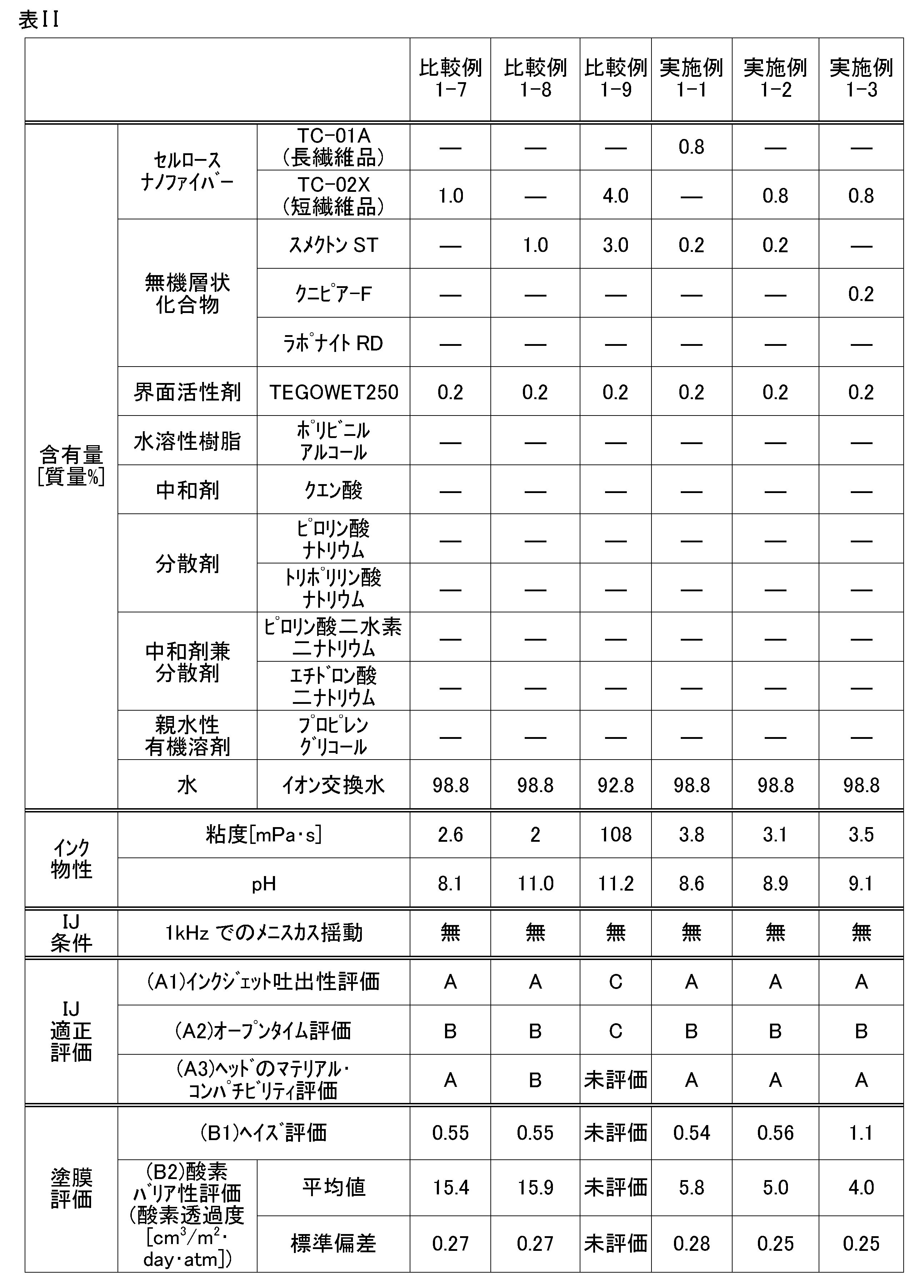
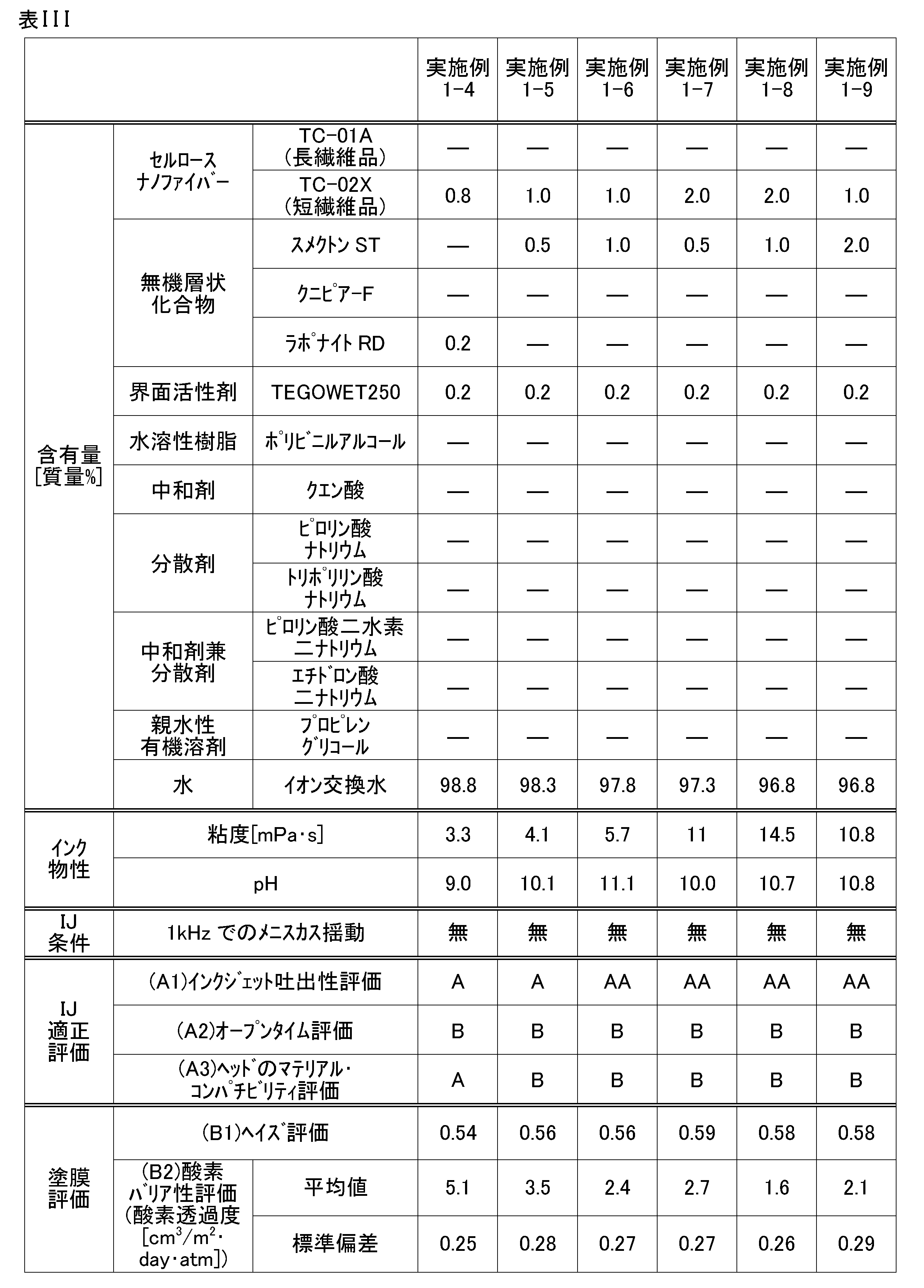
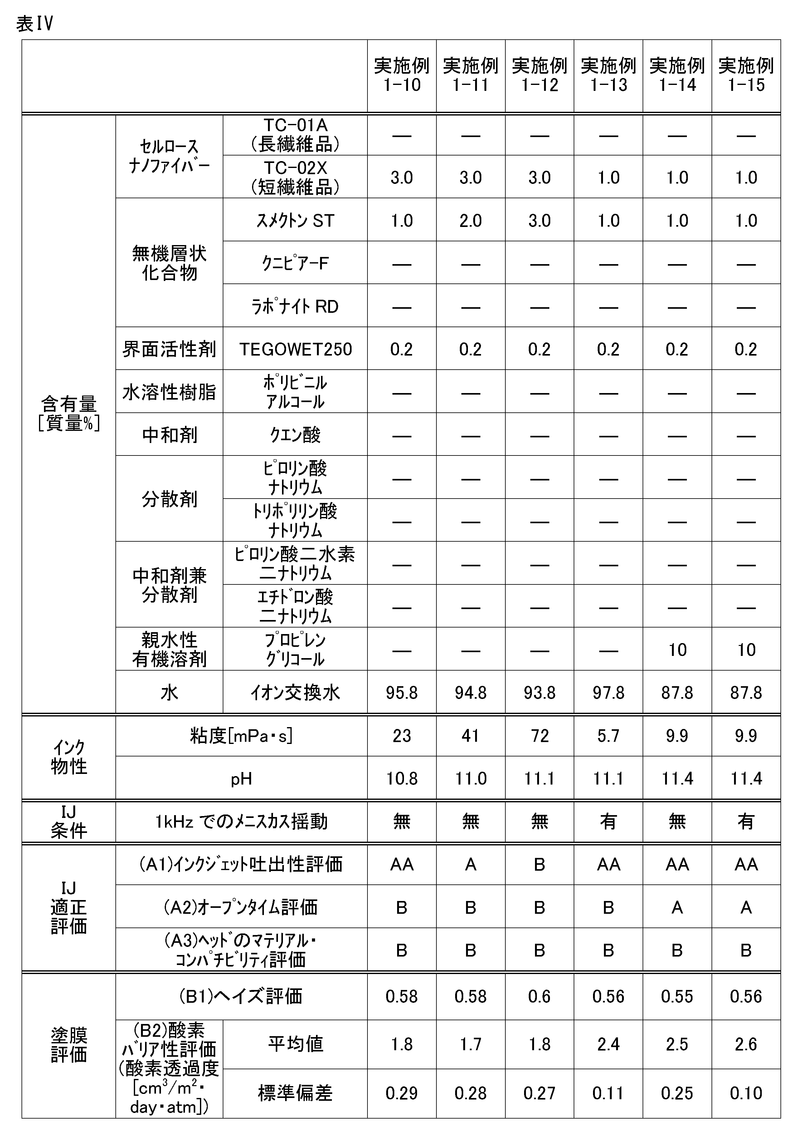

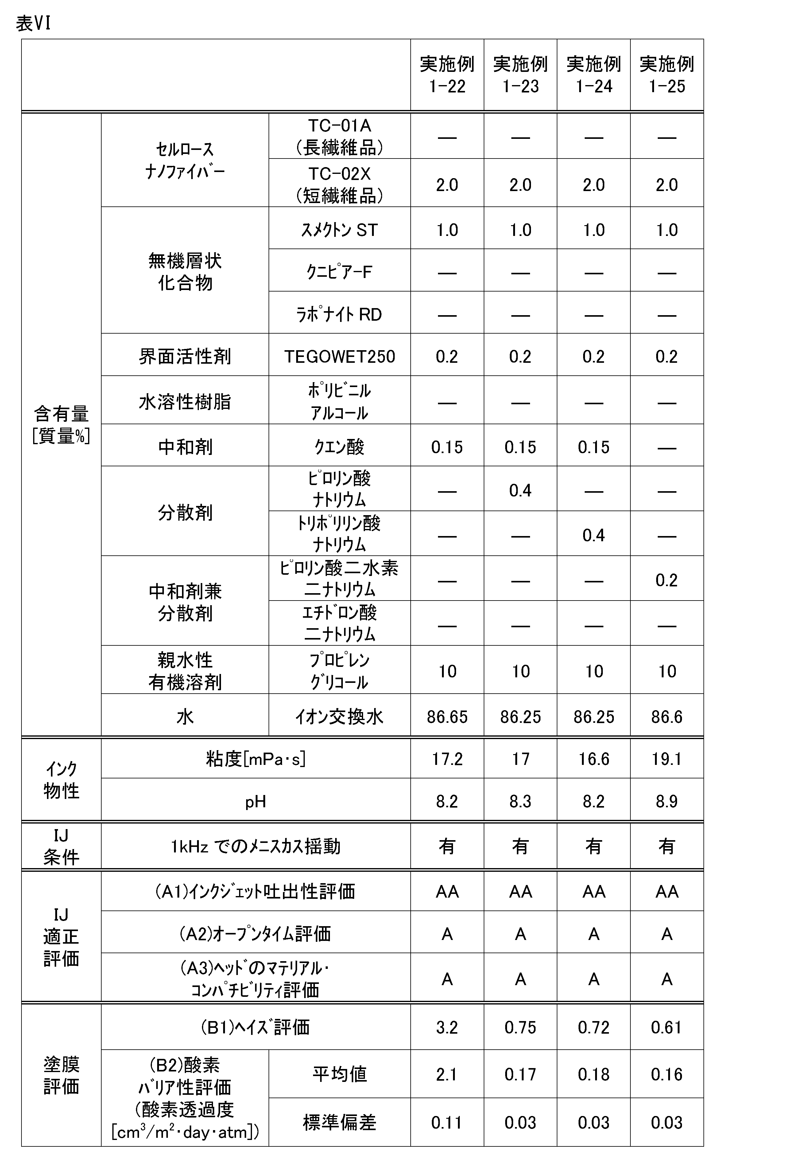
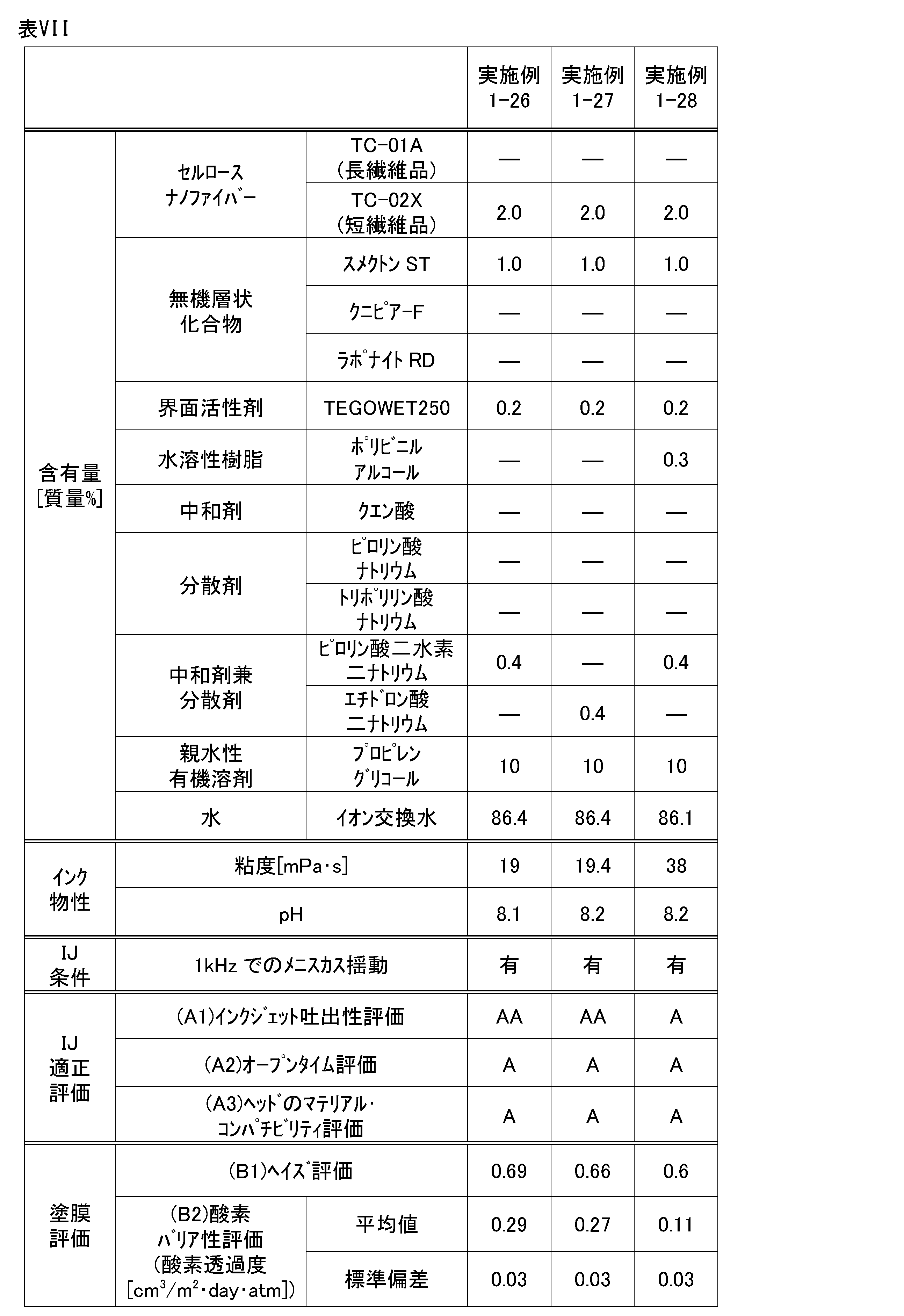
[1]セルロースナノファイバーと層状化合物の合計含有量が1質量%未満では、インクジェット方式での吐出性が優れず、均一なガスバリア膜を形成できないため。
[2]セルロースナノファイバーと層状化合物の合計含有量が1質量%未満では、乾燥前の塗膜を比較的厚くする必要があり、乾燥負荷が大きくなり、均一なガスバリア膜を形成できないため。
実施例2では、基材を変更して、実施例1と同様の塗膜評価を行った。インクには、実施例1-23用のインクを用いた。評価結果は下記表に示すとおりである。
No.1:PETフィルム、フタムラ化学社製、厚さ125μm
No.2:No1のPETフィルムに防曇コーティングされたPETフィルム
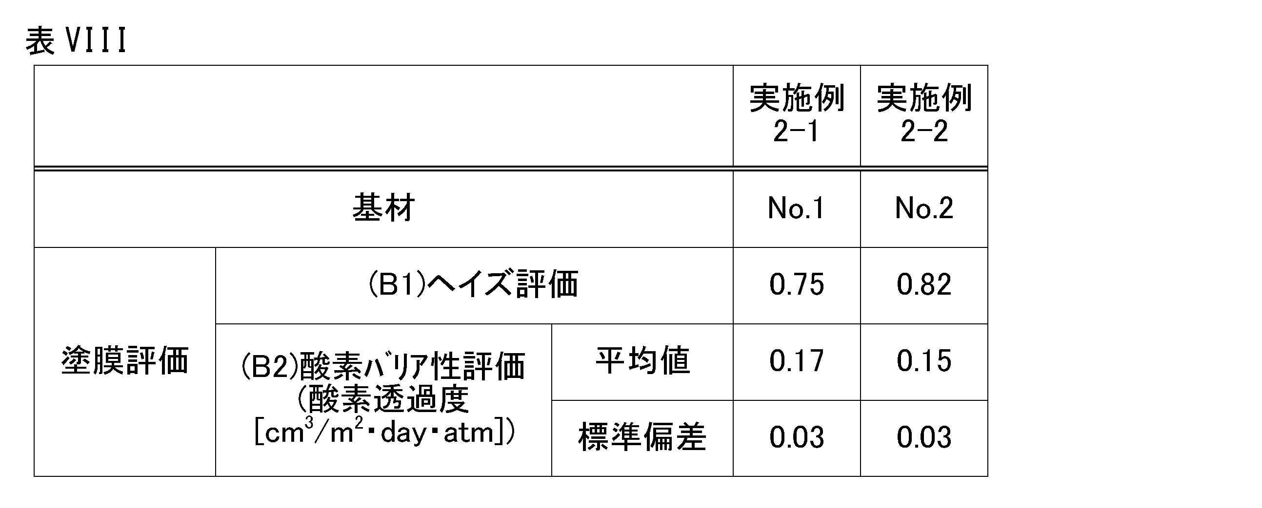
11:インクジェットヘッド(MEMS型)
2:ヘッドチップ
21:ノズルプレート
22:ノズル
23:インクチャネル
24:圧電素子
25:ダミーチャネル
26a:個別インク循環路
28:流路形成溝
3:配線基板
31a:注入孔
31b:排出孔
31c:導入孔
4:インクマニホールド
41:共通インク室
412:インク排出室
421:共通インク循環路
422:溝
423:循環路
424:排出チャネル
425:導入路
425a:導入溝
45:隔壁
5a:インク供給管
5b:インク回収管
5c:インク排出管
5d:循環路連結部
6:バッファ空間部
7a:接続部
7b:接続部
F1:主流路
F2:副流路
100:インクジェット記録装置
101:インクタンク
102:インク移送管
103:インク返送管
104:制御部
104a:制御部
105a:移送ポンプ
105b:返送ポンプ
107:キャリッジ機構
108:搬送手段
109:基材
110a:移送圧力制御ポンプ
110b:返送圧力制御ポンプ
111a:移送側サブタンク
111b:返送側サブタンク
50:基材
51:印刷層
52:オーバーコート層
53:酸素バリア層
54:接着層
55:複合層
55a:酸素バリア性を有する領域
55b:接着性を有する領域
56:被着材
Claims (6)
- 基材上に塗膜を形成するためのインクジェットインクであって、
ガスバリア膜形成用であり、
セルロースナノファイバーと層状化合物とを含有し、
前記セルロースナノファイバーと前記層状化合物の合計含有量が、1質量%以上であり、
せん断速度1000(1/S)時の25℃における粘度が、100mPa・s以下である
インクジェットインク。 - 沸点200℃以下の親水性有機溶剤を5~30質量%の範囲内で含有する
請求項1に記載のインクジェットインク。 - 中和剤を含有し、
25℃におけるpHが、5~10の範囲内である
請求項1に記載のインクジェットインク。 - 前記層状化合物の分散剤を含有する
請求項1に記載のインクジェットインク。 - インクジェットインクを用いた印刷物製造方法であって、
基材に、請求項1から請求項4までのいずれか一項に記載のインクジェットインクをインクジェット方式で吐出し、塗膜を形成する工程を有する
印刷物製造方法。 - 前記インクジェット方式において、ノズルのメニスカスを1kHz以上で常時揺らす
請求項5に記載の印刷物製造方法。
Priority Applications (1)
| Application Number | Priority Date | Filing Date | Title |
|---|---|---|---|
| JP2025502210A JPWO2024176753A1 (ja) | 2023-02-24 | 2024-01-31 |
Applications Claiming Priority (2)
| Application Number | Priority Date | Filing Date | Title |
|---|---|---|---|
| JP2023-026846 | 2023-02-24 | ||
| JP2023026846 | 2023-02-24 |
Publications (1)
| Publication Number | Publication Date |
|---|---|
| WO2024176753A1 true WO2024176753A1 (ja) | 2024-08-29 |
Family
ID=92500754
Family Applications (1)
| Application Number | Title | Priority Date | Filing Date |
|---|---|---|---|
| PCT/JP2024/002971 Ceased WO2024176753A1 (ja) | 2023-02-24 | 2024-01-31 | インクジェットインク及び印刷物製造方法 |
Country Status (2)
| Country | Link |
|---|---|
| JP (1) | JPWO2024176753A1 (ja) |
| WO (1) | WO2024176753A1 (ja) |
Citations (6)
| Publication number | Priority date | Publication date | Assignee | Title |
|---|---|---|---|---|
| JP2004216362A (ja) * | 2002-11-18 | 2004-08-05 | Sumitomo Chem Co Ltd | ガスバリア性成形体の製造方法およびガスバリア性成形体 |
| US20140093648A1 (en) * | 2011-05-05 | 2014-04-03 | Teknologian Tutkimuskeskus Vtt | Method for surface modification of a body |
| JP2014065837A (ja) * | 2012-09-26 | 2014-04-17 | Toppan Printing Co Ltd | ガスバリア層形成用塗工液の製造方法、ガスバリア性積層体及び包装材料 |
| JP2014218579A (ja) * | 2013-05-08 | 2014-11-20 | 凸版印刷株式会社 | ガスバリア層形成用の塗工液及びその製造方法、ガスバリア性積層体及び包装材料 |
| CN110564212A (zh) * | 2019-09-24 | 2019-12-13 | 华南理工大学 | 一种适用于喷墨打印的纳米纤维素墨水 |
| WO2021172007A1 (ja) * | 2020-02-28 | 2021-09-02 | コニカミノルタ株式会社 | インクジェットインク及び画像形成方法 |
-
2024
- 2024-01-31 JP JP2025502210A patent/JPWO2024176753A1/ja active Pending
- 2024-01-31 WO PCT/JP2024/002971 patent/WO2024176753A1/ja not_active Ceased
Patent Citations (6)
| Publication number | Priority date | Publication date | Assignee | Title |
|---|---|---|---|---|
| JP2004216362A (ja) * | 2002-11-18 | 2004-08-05 | Sumitomo Chem Co Ltd | ガスバリア性成形体の製造方法およびガスバリア性成形体 |
| US20140093648A1 (en) * | 2011-05-05 | 2014-04-03 | Teknologian Tutkimuskeskus Vtt | Method for surface modification of a body |
| JP2014065837A (ja) * | 2012-09-26 | 2014-04-17 | Toppan Printing Co Ltd | ガスバリア層形成用塗工液の製造方法、ガスバリア性積層体及び包装材料 |
| JP2014218579A (ja) * | 2013-05-08 | 2014-11-20 | 凸版印刷株式会社 | ガスバリア層形成用の塗工液及びその製造方法、ガスバリア性積層体及び包装材料 |
| CN110564212A (zh) * | 2019-09-24 | 2019-12-13 | 华南理工大学 | 一种适用于喷墨打印的纳米纤维素墨水 |
| WO2021172007A1 (ja) * | 2020-02-28 | 2021-09-02 | コニカミノルタ株式会社 | インクジェットインク及び画像形成方法 |
Also Published As
| Publication number | Publication date |
|---|---|
| JPWO2024176753A1 (ja) | 2024-08-29 |
Similar Documents
| Publication | Publication Date | Title |
|---|---|---|
| JP7677319B2 (ja) | 画像形成方法 | |
| EP3211048B1 (en) | Surface treatment liquid composition, ink set, recording method, and recording device | |
| US10286666B2 (en) | Ink discharge device and ink discharge method | |
| JP7331565B2 (ja) | インクジェット記録液セット、印刷物及びインクジェット記録方法 | |
| CN101537748B (zh) | 喷墨处理液、喷墨记录方法及记录物 | |
| JP7272072B2 (ja) | 水性インクジェットインク、インクジェット記録方法および印刷物 | |
| JP7806954B2 (ja) | 画像形成方法 | |
| JP4609606B1 (ja) | インクジェット印刷インク用バインダー、それを含むインクジェット印刷用インク及び印刷物 | |
| EP4289625B1 (en) | Image formation method | |
| JP7013967B2 (ja) | インク用白色顔料分散体、インク組成物、画像形成方法および画像形成装置 | |
| JP7067249B2 (ja) | 水性インクジェットインク、記録液セット及びインクジェット記録方法 | |
| WO2023001650A1 (en) | Pre-treatment composition for inkjet printing | |
| JP2017119415A (ja) | 記録装置及び記録方法 | |
| JP7167979B2 (ja) | 水性インクジェットインク、印刷物及びインクジェット記録方法 | |
| WO2024176753A1 (ja) | インクジェットインク及び印刷物製造方法 | |
| JP7192376B2 (ja) | インクジェット記録液セット、インクジェット記録用前処理液の製造方法、印刷物及びインクジェット記録方法 | |
| JP7331564B2 (ja) | 水性インクジェットインク、印刷物及びインクジェット記録方法 | |
| WO2019123597A1 (ja) | インクジェット記録用前処理液、その製造方法、インクジェット記録液セット、印刷物及びインクジェット記録方法 | |
| EP4495196A1 (en) | Inkjet recording ink, method for manufacturing inkjet recording ink, inkjet recording ink set, image forming method, and image forming device | |
| WO2019123595A1 (ja) | 水性インクジェットインク、水性インクジェットインクの製造方法、印刷物及びインクジェット記録方法 | |
| WO2024225212A1 (ja) | 画像形成方法及び画像形成システム | |
| WO2024195600A1 (ja) | インクセット、インクジェット記録方法及びインクジェット記録システム |
Legal Events
| Date | Code | Title | Description |
|---|---|---|---|
| 121 | Ep: the epo has been informed by wipo that ep was designated in this application |
Ref document number: 24760060 Country of ref document: EP Kind code of ref document: A1 |
|
| ENP | Entry into the national phase |
Ref document number: 2025502210 Country of ref document: JP Kind code of ref document: A |
|
| WWE | Wipo information: entry into national phase |
Ref document number: 2025502210 Country of ref document: JP |
|
| NENP | Non-entry into the national phase |
Ref country code: DE |
|
| 122 | Ep: pct application non-entry in european phase |
Ref document number: 24760060 Country of ref document: EP Kind code of ref document: A1 |