WO2024176456A1 - 走行データ出力装置、走行データ計測装置、走行データ計測出力装置及びリーン車両データ処理装置 - Google Patents
走行データ出力装置、走行データ計測装置、走行データ計測出力装置及びリーン車両データ処理装置 Download PDFInfo
- Publication number
- WO2024176456A1 WO2024176456A1 PCT/JP2023/006826 JP2023006826W WO2024176456A1 WO 2024176456 A1 WO2024176456 A1 WO 2024176456A1 JP 2023006826 W JP2023006826 W JP 2023006826W WO 2024176456 A1 WO2024176456 A1 WO 2024176456A1
- Authority
- WO
- WIPO (PCT)
- Prior art keywords
- coordinate system
- data
- moving body
- axis
- series
- Prior art date
- Legal status (The legal status is an assumption and is not a legal conclusion. Google has not performed a legal analysis and makes no representation as to the accuracy of the status listed.)
- Ceased
Links
Images



Classifications
-
- B—PERFORMING OPERATIONS; TRANSPORTING
- B62—LAND VEHICLES FOR TRAVELLING OTHERWISE THAN ON RAILS
- B62J—CYCLE SADDLES OR SEATS; AUXILIARY DEVICES OR ACCESSORIES SPECIALLY ADAPTED TO CYCLES AND NOT OTHERWISE PROVIDED FOR, e.g. ARTICLE CARRIERS OR CYCLE PROTECTORS
- B62J45/00—Electrical equipment arrangements specially adapted for use as accessories on cycles, not otherwise provided for
- B62J45/40—Sensor arrangements; Mounting thereof
- B62J45/41—Sensor arrangements; Mounting thereof characterised by the type of sensor
- B62J45/412—Speed sensors
-
- B—PERFORMING OPERATIONS; TRANSPORTING
- B62—LAND VEHICLES FOR TRAVELLING OTHERWISE THAN ON RAILS
- B62J—CYCLE SADDLES OR SEATS; AUXILIARY DEVICES OR ACCESSORIES SPECIALLY ADAPTED TO CYCLES AND NOT OTHERWISE PROVIDED FOR, e.g. ARTICLE CARRIERS OR CYCLE PROTECTORS
- B62J45/00—Electrical equipment arrangements specially adapted for use as accessories on cycles, not otherwise provided for
- B62J45/40—Sensor arrangements; Mounting thereof
- B62J45/41—Sensor arrangements; Mounting thereof characterised by the type of sensor
- B62J45/414—Acceleration sensors
-
- B—PERFORMING OPERATIONS; TRANSPORTING
- B62—LAND VEHICLES FOR TRAVELLING OTHERWISE THAN ON RAILS
- B62J—CYCLE SADDLES OR SEATS; AUXILIARY DEVICES OR ACCESSORIES SPECIALLY ADAPTED TO CYCLES AND NOT OTHERWISE PROVIDED FOR, e.g. ARTICLE CARRIERS OR CYCLE PROTECTORS
- B62J50/00—Arrangements specially adapted for use on cycles not provided for in main groups B62J1/00 - B62J45/00
- B62J50/20—Information-providing devices
- B62J50/21—Information-providing devices intended to provide information to rider or passenger
- B62J50/22—Information-providing devices intended to provide information to rider or passenger electronic, e.g. displays
-
- G—PHYSICS
- G01—MEASURING; TESTING
- G01P—MEASURING LINEAR OR ANGULAR SPEED, ACCELERATION, DECELERATION, OR SHOCK; INDICATING PRESENCE, ABSENCE, OR DIRECTION, OF MOVEMENT
- G01P21/00—Testing or calibrating of apparatus or devices covered by the preceding groups
Definitions
- This invention relates to a driving data output device, a driving data measurement device, a driving data measurement output device, and a lean vehicle data processing device.
- Non-Patent Document 1 discloses that a mobile terminal incorporating the sensor is attached to the steering wheel of a lean vehicle to detect physical quantities related to the behavior of the lean vehicle.
- Non-Patent Document 1 it is required that the screen of the mobile device be as perpendicular to the road as possible and that the mobile device be firmly fixed to the steering wheel of the leaning vehicle or its vicinity in a pre-instructed mounting position so that the mobile device does not tilt left or right.
- Patent Document 1 also discloses a technology for determining whether a measuring device incorporating a sensor that detects a physical quantity related to the behavior of a lean vehicle is correctly attached to the lean vehicle. In other words, Patent Document 1 discloses that the measuring device needs to be attached to the lean vehicle in a pre-specified mounting position.
- Patent Document 2 discloses a behavior information estimation method that uses a three-axis acceleration sensor to estimate behavior information of a lean vehicle that can travel in an inclined state and is equipped with a stand member for allowing the lean vehicle to stand still in the inclined state.
- acceleration measurement values are acquired by the three-axis acceleration sensor in two states: an upright stationary state in which the lean vehicle remains upright and stationary before starting to travel, and an inclined stationary state in which the stand member is used and the lean vehicle remains stationary while inclined.
- the acceleration measurement values of the three-axis acceleration sensor are converted to match the vehicle coordinate system that is predefined for the lean vehicle based on the acceleration measurement values measured in a lean vehicle posture that is pre-instructed before starting to travel.
- the mounting posture of the sensor relative to the lean vehicle depends on the installation action of the installer who mounts the sensor on the lean vehicle. Therefore, it is difficult to make the mounting posture of the sensor relative to the lean vehicle completely match the mounting posture that is instructed in advance.
- the detection accuracy of the physical quantity related to the behavior of the lean vehicle depends on the actions of the installer. Therefore, it is difficult to improve the detection accuracy of the physical quantity related to the behavior of the lean vehicle.
- acceleration and angular velocity measurement values are acquired by a three-axis acceleration sensor and an angular velocity sensor in two states, an upright stationary state and an inclined stationary state of the vehicle, before the vehicle starts traveling.
- the user is instructed to keep the "steering wheel pointed straight ahead" in the two states, an upright stationary state and an inclined stationary state of the vehicle. This is to acquire measurement values in two states where only the attitude of the vehicle in the roll direction has changed without changing the attitude of the vehicle in the pitch direction and yaw direction.
- the present invention aims to provide a driving data output device, a driving data measurement device, a driving data measurement output device, and a lean vehicle data processing device that can obtain highly accurate driving data without relying on the actions of the person who installs the detection device on the moving body.
- the inventors conducted a detailed study of the driving data of lean vehicles in order to obtain highly accurate driving data without relying on the actions of the person who installs the detection device on the moving body.
- a lean vehicle's body tilts to the left when turning left and to the right when turning right. Furthermore, since the lean vehicle has a smaller vehicle width than a four-wheeled vehicle, it may move left and right in the same lane even when traveling along a straight lane. For example, the lean vehicle may travel to the right in the same lane to turn right at an intersection, or to the left in the same lane to turn left at an intersection. Furthermore, if there is a manhole or the like in the center of the lane while traveling in the center of the lane, the lean vehicle may move to either the left or right in the same lane to avoid the manhole and then return to the center of the lane.
- the body tilts more left and right when changing lanes in the same lane compared to a four-wheeled vehicle. Furthermore, in the four-wheeled vehicle, even when changing lanes in the same lane, the body hardly tilts left and right.
- Non-Patent Document 1, Patent Document 1, and Patent Document 2 require that the mounting posture of the sensor mounted by the operator relative to the lean vehicle before starting driving be consistent with a pre-instructed mounting posture, or require that the posture of the lean vehicle on which the sensor is mounted be consistent with a pre-instructed lean vehicle posture when measuring acceleration before starting driving.
- the inventors considered that the sensor mounting posture or lean vehicle posture is required in the prior art as described above because the sensor output data on the lean vehicle while driving has the characteristics described above.
- the inventors also found that because the sensor output data of the lean vehicle while it is running has the above-mentioned characteristics, it is difficult to adopt the sensor output data processing technology for four-wheeled vehicles, as has been considered for the sensor output data of four-wheeled vehicles, to a lean vehicle.
- the inventors have further investigated the driving data of lean vehicles in order to obtain highly accurate driving data without relying on the actions of the person who installs the detection device on the moving body.
- a certain amount of data measured by the sensor may be required. For example, when calculating insurance rates for a lean vehicle or evaluating the driver's skills, a certain amount of data is required to ensure accuracy.
- the lean vehicle in order to accumulate a certain amount of data, it is assumed that the lean vehicle will travel a corresponding distance. Furthermore, it is assumed that the driving state of the lean vehicle until a certain amount of data is accumulated will include a mixture of straight scenes and turning scenes. Note that turning scenes also include left and right turns at intersections. For this reason, once a certain amount of data has been accumulated, it becomes easier to grasp the trends in the driving state of the lean vehicle.
- the sensor output data with a certain amount of data may include a speed change cycle's worth of sensor output data.
- the speed change cycle refers to one period of speed change of the lean vehicle during the period from when the lean vehicle's moving body posture and the moving body speed in the forward/rearward direction change from a predetermined state until when the lean vehicle returns to the predetermined state.
- the inventors came up with the following configuration for a driving data output device that outputs driving data based on the detection data of the sensor, so as to improve user convenience while enabling highly accurate driving data to be obtained.
- a driving data output device is a driving data output device having a driving data output processor that is mounted on a moving body by an operator so as to be fixed thereto, and outputs driving data in the coordinate system of the moving body based on the output of a detection device that detects physical quantities related to the behavior of the moving body, and the driving data output processor outputs acceleration in three coordinate axis directions and is mounted on the moving body in a mounting position determined by the operator's free will rather than a mounting position that is specified in advance, and outputs angular velocities around the three coordinate axes and detects the driving data in a mounting position determined by the operator's free will rather than a mounting position that is specified in advance.
- the time-series running data being output in a time series manner from the detection device including an angular velocity sensor mounted on the vehicle body, and including speed data of the vehicle body, acceleration data in three coordinate axis directions in the coordinate system of the acceleration sensor, and angular velocity data about three coordinate axes in the coordinate system of the angular velocity sensor, the time-series running data being output in a time series manner from the detection device including an angular velocity sensor mounted on the vehicle body ...
- the time-series running data being acquired for at least a speed change cycle from when the vehicle body attitude and the vehicle body speed in the forward/rearward direction change from a predetermined state while the vehicle body is running at a mobile body attitude and mobile body speed determined by the free will of the vehicle user rather than a mobile body attitude and mobile body speed that are instructed in advance, until the mobile body returns to the predetermined state, and the time series running data for the acquired speed change cycle Among the time-series travel data, at least the time-series travel data when the moving body attitude and the moving body speed in the forward/backward direction change from the predetermined state and the time-series travel data when the moving body attitude and the moving body speed in the forward/backward direction return to the predetermined state are used to make three coordinate axes in the coordinate system of the acceleration sensor and the angular velocity
- the coordinate system is converted from the coordinate system of the acceleration sensor and the angular velocity sensor to the coordinate system of the moving body, and the time-series running data for at least the speed change cycle is output.
- This is different from the data acquired by the detection device mounted in a pre-instructed mounting attitude and the data acquired by the detection device before starting running in a pre-instructed moving body attitude, and is configured to perform the coordinate system conversion based on the time-series running data for at least the speed change cycle acquired while running in a moving body attitude and moving body speed at the free will of the user by the detection device mounted in a mounting attitude at the free will of the user.
- the time series travel data for a speed change cycle is acquired from when the mobile body attitude and the mobile body speed in the forward/reverse direction change from a predetermined state to when the mobile body returns to the predetermined state.
- the time series travel data for the speed change cycle acquired in this way includes both the time series travel data when changing from a predetermined state and the time series travel data when returning to the predetermined state.
- the time series travel data for the speed change cycle acquired in this way includes time series travel data in different attitudes, acceleration states, and deceleration states.
- the time series travel data is a continuous data group, the calculation and statistical processing of the time series travel data is easy.
- the yaw axis (Z axis) in the coordinate system of the mobile body can be easily estimated.
- the speed and angular velocity included in at least the time series travel data for the speed change cycle the straight line travel scene and/or turning scene of the mobile body can be easily estimated.
- the speed and acceleration included in the time series travel data for at least the speed change cycle the forward/reverse direction of the mobile body can be easily estimated.
- the predetermined state may be when the moving body is traveling at an extremely low speed or is stopped.
- Batch processing is performed on a certain amount of data, so it is possible to achieve both accuracy and convenience.
- the driving data output device of the present invention includes the following configuration:
- the driving data output processor makes a first axis of the sensor coordinate system, which is one of the three coordinate axes in the coordinate system of the sensor, parallel to or coincident with a first axis of the moving body coordinate system, which is one of the three coordinate axes in the coordinate system of the moving body.
- the above-mentioned configuration allows the degree of freedom in the conversion process of time-series driving data to be reduced, making it easier to realize the conversion process of time-series driving data.
- the traveling data output device of the present invention includes the following configuration.
- the traveling data output processor aligns a direction based on the sensor in the first axis of the sensor coordinate system with a direction based on the moving body in the first axis of the moving body coordinate system, with the first axis of the sensor coordinate system being parallel to or aligned with the first axis of the moving body coordinate system.
- the above-mentioned configuration allows the degree of freedom in the conversion process of time-series driving data to be reduced, making it easier to realize the conversion process of time-series driving data.
- the traveling data output device of the present invention includes the following configuration.
- the traveling data output processor makes the first axis of the sensor coordinate system parallel to or coincides with the first axis of the moving body coordinate system, and aligns the direction based on the sensor in the first axis of the sensor coordinate system with the direction based on the moving body in the first axis of the moving body coordinate system, and makes the remaining coordinate axes other than the first axis of the sensor coordinate system among the three coordinate axes in the sensor's coordinate system parallel to or coincide with the remaining coordinate axes other than the first axis of the moving body coordinate system among the three coordinate axes in the moving body's coordinate system, and aligns the direction based on the sensor in the remaining coordinate axes other than the first axis of the sensor coordinate system with the direction based on the moving body in the remaining coordinate axes other than the first axis of the moving body coordinate system.
- the first axis of the sensor coordinate system and its orientation are determined relative to the first axis of the moving body coordinate system. Therefore, the degree of freedom in the conversion process can be reduced accordingly. This makes it easier to convert the remaining coordinate axes.
- the traveling data output device of the present invention includes the following configuration.
- the traveling data output processor makes the remaining coordinate axes other than the first axis of the sensor coordinate system among the three coordinate axes in the sensor's coordinate system parallel to or coincident with the remaining coordinate axes other than the first axis of the moving body coordinate system among the three coordinate axes in the moving body's coordinate system.
- the traveling data output device of the present invention includes the following configuration:
- the first axis of the moving body coordinate system is a vertical axis extending in the vertical direction in the moving body coordinate system, or a front-rear axis extending in the front-rear direction in the moving body coordinate system.
- the up-down axis in the coordinate system of the moving body corresponds to the direction of gravity
- the front-rear axis in the coordinate system of the moving body corresponds to the direction of travel.
- the traveling data output device of the present invention includes the following configuration:
- the first axis of the moving body coordinate system is an up-down axis extending in the up-down direction in the coordinate system of the moving body, and the traveling data output processor makes the first axis of the sensor coordinate system parallel to or coincides with the up-down axis in the coordinate system of the moving body, and while the first axis of the sensor coordinate system is aligned with the orientation of the up-down axis in the coordinate system of the moving body, makes the second axis of the sensor coordinate system, which is one of the remaining coordinate axes of the sensor coordinate system, parallel to or coincides with the front-rear axis extending in the front-rear direction in the coordinate system of the moving body, thereby aligning the orientation of the second axis of the sensor coordinate system to the orientation of the front-rear axis in the coordinate system of the moving body.
- the driving data output processor first identifies the vertical axis and the direction of the vertical axis.
- the vertical axis in the coordinate system of the moving body corresponds to the direction of gravity.
- the remaining left-right axis and the front-rear axis can be aligned.
- the driving data measuring device includes the following configuration.
- the driving data measuring device is configured to be mountable on the moving body, and measures time-series driving data for at least the speed change cycle used for coordinate system conversion in the driving data output device.
- the driving data measuring device comprises the detection device including the acceleration sensor and the angular velocity sensor, and a measurement processor.
- the measurement processor acquires time-series driving data including time-series speed data of the moving body, acceleration data in the three coordinate axis directions in the coordinate system of the acceleration sensor and angular velocity data about the three coordinate axes in the coordinate system of the angular velocity sensor outputted in a time-series manner from the detection device while the driving data measuring device is mounted on the moving body in a mounting attitude determined by the user's free will rather than a mounting attitude previously instructed by the user, and while the driving data measuring device is traveling at a moving body attitude and moving body speed determined by the user's free will rather than a previously instructed moving body attitude and moving body speed, and outputs the time-series driving data including time-series speed data of the moving body and acceleration data in the three coordinate axis directions in the coordinate system of the acceleration sensor and angular velocity data about the three coordinate axes in the coordinate system of the angular velocity sensor outputted in a time-series manner from the detection device.
- the time-series running data which includes at least a cycle of speed change from when the mobile body attitude and the mobile body speed in the forward/reverse direction change from the predetermined state while running at a mobile body attitude and mobile body speed based on the free will of the user rather than a pre-instructed mobile body attitude and mobile body speed, to when the mobile body returns to the predetermined state, is output in a format that is the coordinate system of the acceleration sensor and the angular velocity sensor and that can be converted by the running data output processor of the running data output device, rather than in a format that is converted from the coordinate system of the acceleration sensor and the angular velocity sensor to the coordinate system of the mobile body.
- the time-series driving data can be output in a format that can be converted into a coordinate system by the driving data output processor of the driving data output device. Therefore, the driving data measurement device can output time-series driving data that is suitable for the coordinate system conversion process of the driving data output device.
- the above-mentioned configuration makes it possible to provide a driving data output device that can obtain highly accurate driving data without relying on the actions of the person who installs the detection device on the moving object.
- the driving data measuring device of the present invention includes the following configuration.
- the driving data measuring device further includes a communication device with an external device, and the measurement processor outputs, from the acquired time-series driving data, the time-series driving data including at least a cycle of speed change from when the mobile body attitude and the mobile body speed in the longitudinal direction change from the predetermined state while driving at a mobile body attitude and mobile body speed based on the free will of the user, rather than a previously instructed mobile body attitude and mobile body speed, to when the mobile body returns to the predetermined state, not in a format converted from the coordinate system of the acceleration sensor and the angular velocity sensor to the coordinate system of the mobile body, but in a format that is the coordinate system of the acceleration sensor and the angular velocity sensor and that can be converted by the driving data output processor of the driving data output device, to the outside of the driving data measuring device via the communication device.
- the above-mentioned configuration provides a driving data measurement device for supplying time-series driving data to a driving data output device that performs coordinate conversion processing. This allows the driving data measurement device and the driving data output device to be realized by separate devices. In this way, the present invention can also be realized by separate devices.
- the traveling data output device of the present invention includes the following configuration.
- the traveling data output device performs the coordinate system conversion based on the time-series traveling data for at least the speed change cycle acquired by the traveling data measurement device.
- the traveling data output device further includes a communication device with an external device, and the traveling data output processor acquires the time-series traveling data for at least the speed change cycle via the communication device, and converts the acquired time-series traveling data for at least the speed change cycle from the coordinate system of the acceleration sensor and the angular velocity sensor to the coordinate system of the moving body using both the time-series traveling data when the moving body attitude and the moving body speed in the forward and backward directions change from the predetermined state and the time-series traveling data when the moving body attitude and the moving body speed in the forward and backward directions return to the predetermined state out of the time-series traveling data for at least the speed change cycle acquired via the communication device, and outputs the coordinate system conversion of the acquired time-series traveling data for at least the speed change cycle from the
- the above-mentioned configuration provides a driving data output device that performs coordinate conversion processing based on time-series driving data supplied from a driving data measurement device. This allows the driving data measurement device and the driving data output device to be realized by separate devices. In this way, the present invention can also be realized by separate devices.
- the driving data measurement output device includes the following configuration.
- the driving data measurement output device has the driving data output device and the driving data measurement device.
- the driving data output processor and the measurement processor are configured by a single processor that is electrically connected to a memory and housed in a housing mounted on the moving body.
- the single processor acquires time-series driving data including time-series speed data of the moving body and acceleration data in the three coordinate axis directions in the coordinate system of the acceleration sensor and angular velocity data about the three coordinate axes in the coordinate system of the angular velocity sensor output in a time-series manner from the detection device while the housing is mounted on the moving body in a mounting attitude determined by the free will of the mounter rather than a mounting attitude previously instructed by the mounter, and while the moving body is traveling at a moving body attitude and moving body speed determined by the free will of the mounter rather than a moving body attitude and moving body speed previously instructed, and among the acquired time-series driving data, selects data in the moving body attitude and the time-series travel data including at least a speed change cycle after the mobile body attitude and the mobile body speed in the forward/reverse direction change from the predetermined state while traveling at a mobile body attitude and mobile body speed based on the free will of the user, rather than a mobile body speed based on the mobile body attitude and the mobile body speed
- the time-series travel data when the attitude of the moving body and the speed of the moving body in the forward and backward directions change from the predetermined state and the time-series travel data when the attitude of the moving body and the speed of the moving body in the forward and backward directions return to the predetermined state are used to make three coordinate axes in the coordinate system of the acceleration sensor and the angular velocity sensor parallel to or coincide with three coordinate axes in the coordinate system of the moving body, and to make the forward and backward directions, the up and down directions and the left and right directions based on the acceleration sensor and the angular velocity sensor different from each other in the forward and backward directions, the up and down directions and the left and right directions based on the moving body.
- the coordinate system is converted from the coordinate system of the acceleration sensor and the angular velocity sensor to the coordinate system of the moving body to convert the acquired time-series travel data for at least a speed change cycle into the coordinate system of the moving body so that the coordinate system is consistent with the data acquired by the detection device mounted in a pre-specified mounting attitude and the data acquired before the start of travel in a pre-specified moving body attitude, and the coordinate system is converted based on the time-series travel data for at least a speed change cycle acquired while traveling in a moving body attitude and moving body speed at the free will of the user by the detection device mounted in a mounting attitude at the free will of the user.
- the above-mentioned configuration provides a driving data measurement output device that has both the functions of a driving data output device and a driving data measurement device. This allows the driving data measurement output device to perform coordinate conversion processing on its own. In addition, since there is no need for communication between the driving data measurement device and the driving data output device, it is possible to avoid being affected by the network.
- the lean vehicle data processing device preferably includes the following configuration.
- the lean vehicle data processing device includes any one of the driving data output device, the driving data measurement device, and the driving data measurement output device.
- the moving body includes a lean vehicle in which the body tilts to the left when turning left and to the right when turning right, and the time-series driving data for at least a speed change cycle acquired by the driving data output processor and used for coordinate system transformation is acquired while traveling at a moving body attitude and moving body speed based on the free will of the user, rather than a previously instructed moving body attitude and moving body speed, and is time-series driving data for a speed change cycle from when the moving body attitude, including at least the left-right tilt attitude of the moving body, and the moving body speed in the front-rear direction of the moving body, change from the predetermined state to when they return to the predetermined state, and the coordinate system transformation is performed using the time-series driving data for at least a speed change cycle including at least a change
- connection As used herein, the terms “attached,” “connected,” “coupled,” and/or their equivalents are used broadly to encompass both “direct and indirect” attachments, connections, and couplings. Furthermore, “connected” and “coupled” are not limited to physical or mechanical connections or couplings, but can include direct or indirect electrical connections or couplings.
- This specification describes an embodiment of a driving data output device according to the present invention.
- a lean vehicle is a vehicle that turns in a leaning posture.
- a lean vehicle is a vehicle that, in the left-right direction of the vehicle, leans to the left when turning left and leans to the right when turning right.
- a lean vehicle may be a vehicle for one person or a vehicle that can accommodate multiple people.
- lean vehicles include not only two-wheeled vehicles, but also three-wheeled and four-wheeled vehicles.
- lean vehicles are not limited in the number of wheels or the presence or absence of wheels, and include all vehicles that turn in a leaning posture.
- Lean vehicles also include scooters and the like.
- the moving mechanism includes a device driven by human power and a device equipped with a power unit such as an engine and a motor.
- the moving body may or may not have wheels as the moving mechanism.
- the moving body includes a terrestrial moving body, a surface moving body, an underwater moving body, and an aerial moving body.
- the moving body includes not only a moving body driven by a pilot or a driver, but also a moving body that moves autonomously.
- the ground moving body includes two-wheeled vehicles (e.g., motorcycles and bicycles) and four-wheeled vehicles (e.g., automobiles).
- the ground moving body also includes devices having wheels, caterpillar tracks, and other ground moving mechanisms.
- the ground moving body also includes snow bikes that move on snow.
- the ground moving body may have a moving mechanism other than wheels, such as skis.
- the above water-based vehicles include small and large ships.
- the above water-based vehicles also include vehicles that travel on the sea.
- the underwater vehicles include submarines and ROVs (remotely operated vehicles).
- the aerial vehicle includes aircraft, unmanned aerial vehicles such as drones.
- the moving object also includes an artificial satellite or spacecraft that moves in a satellite orbit within the gravitational field.
- a moving body may refer in particular to a moving body that moves in one direction and in which gravity acts downward on the vertical axis of the moving body in a straight line at the start and end of the movement.
- the three coordinate axes refer to three axes, namely, an X-axis, a Y-axis, and a Z-axis, which are mutually orthogonal.
- the three coordinate axes are coordinate axes when a reference object is located at the origin.
- the coordinate system of a sensor is constituted by three coordinate axes based on a sensor.
- the coordinate system of a moving body is constituted by three coordinate axes based on a moving body.
- the three coordinate axes are also called a roll axis extending in the front-rear direction relative to the vehicle, a pitch axis extending in the left-right direction relative to the vehicle, and a yaw axis extending in the vertical direction relative to the vehicle.
- the coordinate system of the moving body includes, but is not limited to, the coordinate system of the designed moving body. It also includes a coordinate system of the moving body estimated based on the driving characteristics indicated by the driving data. In other words, the coordinate system of the moving body includes a coordinate system that is approximated to the coordinate system of the designed moving body.
- a physical quantity related to the behavior of a moving object means a physical quantity that changes due to the attitude or movement of the moving object, and includes at least one of the velocity, acceleration, and deceleration of the moving object in three axial directions (forward/backward, left/right, and up/down directions), and the angle, angular velocity, and angular acceleration around three axes (roll axis, yaw axis, and pitch axis).
- the physical quantity refers to a physical quantity including at least one of a physical quantity related to a roll motion, a physical quantity related to a yaw motion, and a physical quantity related to a pitch motion of a moving body, which are acquired while the moving body is traveling.
- the physical quantity is data including at least one of information on velocity, acceleration, jerk, angle, angular velocity, angular acceleration, position information, etc., related to at least one of roll, yaw, and pitch.
- the traveling data is data related to the traveling of a mobile object.
- the traveling data includes data based on the output of a sensor that detects a physical quantity related to the behavior of the mobile object.
- the traveling data may also include at least one of mobile object driving input data related to a driving input to the mobile object by a driver, mobile object behavior data related to the behavior of the mobile object, mobile object position data related to the traveling position of the mobile object, and mobile object traveling environment data related to the traveling environment in which the mobile object travels.
- time-series driving data refers to driving data that is output in a time series. Outputting in a time series means outputting in a time order according to the time.
- the time-series driving data includes information that combines the driving data and the time at which the driving data is output.
- a direction based on an object means a direction as seen from the object. If the object is a moving object, it is a direction as seen from the moving object. For example, if the moving object is a lean vehicle, it is a direction as seen from a driver riding in the lean vehicle. If the object is a sensor, it is a direction as seen from the sensor.
- the direction of a coordinate axis refers to the positive and negative directions of the coordinate axis.
- Matching the directions of two coordinate axes means, for example, matching the positive directions of the two coordinate axes.
- the acceleration in the three coordinate axis directions means the acceleration in the directions parallel to the three axes (X-axis, Y-axis, and Z-axis) of a coordinate system based on an object. If the object is, for example, a moving object, the acceleration in the three coordinate axis directions means the acceleration in the three axial directions of the moving object, namely, the "forward/rearward direction,” the "left/right direction,” and the "up/down direction.”
- the three coordinate axis directions mean the directions in which the X-axis, Y-axis, and Z-axis extend, respectively.
- the angular velocity about three coordinate axes means the angular velocity when an object rotates about each of three axes (X-axis, Y-axis, and Z-axis) of a coordinate system based on the object. If the object is, for example, a moving object, the angular velocity about three coordinate axes means the angular velocity when the moving object rotates about the roll axis, pitch axis, and yaw axis.
- a speed change cycle means one period of the speed change of the moving body during operation from when the moving body attitude and the moving body speed in the forward and backward directions change from a predetermined state to when they return to the predetermined state.
- the moving body attitude may be defined based on the direction of gravity. That is, the moving body attitude may be determined based on which direction the moving body faces in the up-down direction, left-right direction, and forward-backward direction with respect to the direction of gravity.
- the predetermined state may be a stopped state of the moving body.
- the speed change cycle may mean, for example, one period of the speed change of the moving body from when the moving body starts from a stopped state to when it stops thereafter.
- the moving body attitude at the start and end of the speed change cycle may be in an upright state or in an inclined state.
- the speed of the moving body at the start and end of the speed change cycle may be zero or a value other than zero.
- the time-series travel data for the speed change cycle may be a part or the whole of the time-series travel data acquired during one travel period from the start to the end of travel, so long as it includes a period from when the attitude of the moving body and the forward/rearward speed of the moving body change from a predetermined state to when they return to the predetermined state.
- one travel period may include one or a plurality of speed change cycles.
- the start and end of the speed change cycle and one or more acceleration and deceleration sections between the start and end may or may not include left and right turns at an intersection and cornering at a curve.
- the speed change cycle may include a stopped state or a very low speed state.
- the predetermined state may be a stopped state in which the posture of the lean vehicle is upright with respect to the ground.
- the speed change cycle may be, for example, one period of the speed change of the lean vehicle during a period from a stopped state in which the posture of the lean vehicle is upright with respect to the ground to a stopped state in which the posture of the lean vehicle is finally returned to a stopped state in which the posture of the lean vehicle is upright with respect to the ground.
- the stopped state of the lean vehicle includes not only an upright state of the lean vehicle but also a parked state in which the vehicle is parked by the center stand or the side stand, and an inclined state in which the driver stops with one foot on the ground in a scene such as waiting for a traffic light.
- converting time series driving data for at least a speed change cycle in the sensor's coordinate system into time series driving data for at least a speed change cycle in the coordinate system of the moving body means converting time series driving data for at least a speed change cycle in the sensor's coordinate system into time series driving data for at least a speed change cycle in the coordinate system of the moving body so that the three coordinate axes in the sensor's coordinate system are parallel to or coincident with the three coordinate axes in the coordinate system of the moving body, and so that the forward/backward, upward/downward and left/right directions based on the sensor match the forward/backward, upward/downward and left/right directions based on the moving body.
- a driving data output device a driving data measurement device, a driving data measurement output device, and a lean vehicle data processing device that can obtain highly accurate driving data without relying on the actions of the person who installs the detection device on the moving body.
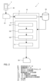
- FIG. 1 is a diagram showing a schematic configuration of a driving data output device according to a first embodiment of the present invention.
- FIG. 2 is a block diagram showing a schematic configuration of a running data output processor included in the running data output device shown in FIG.
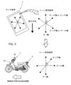
- FIG. 3 is a diagram for explaining the principle by which the coordinate transformation data generating unit shown in FIG. 2 makes the three coordinate axes in the sensor's coordinate system parallel to the three coordinate axes in the lean vehicle's coordinate system based on the acceleration.
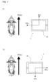
- FIG. 4 is a diagram for explaining the principle by which the coordinate transformation data generating unit shown in FIG.
- FIG. 5 is a functional block diagram showing a schematic configuration of a coordinate transformation data generating unit included in a driving data output device according to the second embodiment of the present invention.
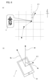
- 6A and 6B are diagrams for explaining the principle by which the coordinate transformation data generating unit shown in FIG.
- FIG. 5 determines front and rear based on geomagnetism, where (a) is a diagram showing the direction based on GPS, and (b) is a diagram showing the direction based on geomagnetism.
- 7A and 7B are diagrams for explaining the principle by which the coordinate transformation data generating unit shown in FIG. 5 determines front-to-back based on the relationship between the acceleration obtained from the GPS speed and the direction of the X-axis acceleration, in which (a) is a diagram showing a case where the front-to-back is correct, and (b) is a diagram showing a case where the front-to-back is not correct.
- FIG. 1 A driving data output device according to a first embodiment of the present invention will be described with reference to FIGS. 1 to 4.
- FIG. 1 A driving data output device according to a first embodiment of the present invention will be described with reference to FIGS. 1 to 4.
- FIG. 1 A driving data output device according to a first embodiment of the present invention will be described with reference to FIGS. 1 to 4.
- FIG. 1 A driving data output device according to a first embodiment of the present invention will be described with reference to FIGS. 1 to 4.
- the traveling data measuring device 5 is configured to be mountable on a lean vehicle X as a mobile body, and measures time-series traveling data for at least the speed change cycle used for coordinate system transformation in the traveling data output device 1 described later.
- the traveling data measuring device 5 is realized as, for example, a mobile terminal Y.
- the driving data measuring device 5 includes a detection device 30 and a measurement processor 50.
- the detection device 30 is built into a mobile terminal Y that is mounted on the lean vehicle X in a mounting position determined by the user's free will, rather than a pre-instructed mounting position.
- the detection device 30 includes sensors that can detect the speed of the lean vehicle X, acceleration in three axial directions (forward/backward, upward/downward, and left/right) based on the detection device 30, and angular velocity around three axes (roll axis, yaw axis, and pitch axis).
- the detection device 30 includes, for example, an inertial measurement unit (IMU) having an acceleration sensor 31 and an angular velocity sensor 32.
- IMU inertial measurement unit
- the detection device 30 may be a sensor other than an IMU as long as it can detect at least the speed of the lean vehicle X, the acceleration in the three coordinate axis directions in the coordinate system of the detection device 30, and the angular velocity around the three coordinate axes in the coordinate system of the detection device 30.
- the detection device 30 may be an IMU combined with other sensors.
- the detection device 30 also includes a GPS (Global Positioning System) mounted on the mobile terminal Y.
- the detection device 30 is a sensor capable of outputting the speed of the lean vehicle X based on GPS positioning data.
- the detection device 30 may also include a speed sensor capable of outputting the speed without based on GPS positioning data.
- the detection device 30 may be configured such that the GPS sensor is combined with another sensor.
- the detection device 30 may be configured such that the speed sensor is combined with another sensor.
- the detection device 30 may be a combination of one sensor capable of detecting one or more types of physical quantities among the speed of the lean vehicle X, the acceleration in the three coordinate axis directions, and the angular velocity around the three coordinate axes, and one or more sensors capable of detecting the remaining types of physical quantities.
- the detection device 30 may be capable of detecting at least one of the jerk in the three axis directions, and the angle or angular acceleration around the three axes.
- the mobile terminal Y which serves as the driving data measuring device 5, is attached to the handlebar of the lean vehicle X.
- the person who installs the mobile terminal Y on the lean vehicle X may be the driver of the lean vehicle X or a technician who performs maintenance on the lean vehicle X.
- the detection device 30 built into the mobile terminal Y attached to the handlebar of the lean vehicle X detects data of physical quantities related to the behavior of the lean vehicle X in a coordinate system based on the detection device 30, and outputs it as driving data.
- the detection data detected by the detection device 30 is not data in a coordinate system based on the lean vehicle X, but data in a coordinate system based on the detection device 30.
- the driving data output by the detection device 30 includes physical quantities such as speed in three axial directions (forward/backward, up/down, and left/right) in the coordinate system of the detection device 30, acceleration and jerk in the three coordinate axis directions in the coordinate system of the detection device 30, angles around three coordinate axes (roll axis, yaw axis, pitch axis) in the coordinate system of the detection device 30, angular velocity, and angular acceleration.
- the detection device 30 outputs the driving data in chronological order to the driving data output device 1.
- a speed change cycle is defined as one period of speed change of the lean vehicle X during the period from a predetermined state in which the lean vehicle X is upright relative to the ground (mobile body posture) and the forward/backward speed (mobile body speed) is zero until the lean vehicle X accelerates and decelerates one or more times and finally reaches the predetermined state in which the lean vehicle X is upright relative to the ground and the forward/backward speed is zero.
- the detection device 30 outputs the driving data in a time series manner to the driving data output device 1 for at least one speed change cycle.
- the driving data output by the detection device 30 in a time series manner will be referred to as "time series driving data.”
- the driving data measuring device 5 is mounted on the lean vehicle X as a moving body in a mounting posture determined by the user's free will, rather than a mounting posture instructed in advance by the user.
- the detection device 30 acquires time-series driving data D1 including time-series speed data of the lean vehicle X as a moving body, acceleration data in the three coordinate axis directions in the coordinate system of the acceleration sensor 31 and angular velocity data about the three coordinate axes in the coordinate system of the angular velocity sensor 32 output in time series from the detection device 30.
- the measurement processor 50 outputs the time-series driving data D1 to the driving data output device 1.
- the time-series driving data D1 includes at least a cycle of speed change from when the vehicle attitude and the vehicle speed in the longitudinal direction change from a predetermined state while driving at a vehicle attitude and vehicle speed based on the free will of the user, rather than a previously instructed vehicle attitude and vehicle speed, to when the vehicle returns to the predetermined state, among the acquired time-series driving data D1.
- the measurement processor 50 outputs the time-series driving data D1 not in a format converted from the coordinate system of the acceleration sensor 31 and the angular velocity sensor 32 to the coordinate system of the lean vehicle X as a moving body, but in a format that is the coordinate system of the acceleration sensor 31 and the angular velocity sensor 32 and that can be converted by the driving data output processor 10 of the driving data output device 1 described later.
- the time-series driving data D1 can be output in a format that can be converted into a coordinate system by the driving data output processor 10 of the driving data output device 1. Therefore, the driving data measurement device 5 can output time-series driving data that is suitable for the coordinate system conversion process of the driving data output device 1.
- (Travel data output device) 1 is a diagram showing a schematic configuration of a running data output device 1 according to a first embodiment of the present invention.
- the running data output device 1 is mounted by an operator so as to be fixed to a lean vehicle X as a moving body, and is a device that outputs running data in a coordinate system of the lean vehicle X based on the output of a detection device 30 that detects physical quantities related to the behavior of the lean vehicle X.
- the driving data output device 1 has a driving data output processor 10 and a memory 20.
- the memory 20 may be a memory capable of temporary storage, or may be a non-volatile readable/writable storage medium such as a flash memory or a hard disk.
- the memory 20 may have any configuration as long as it is capable of temporarily or permanently storing data acquired or calculated by the driving data output processor 10.
- the memory 20 stores time-series driving data D1 for at least one speed change cycle output from a detection device 30 built into a mobile terminal Y attached to the handlebar of a lean vehicle X.
- the time-series driving data D1 stored in the memory 20 includes speed data D21, acceleration data D22, and angular velocity data D23 of the lean vehicle X.
- the speed data D21 is speed data related to the speed at which the lean vehicle X is traveling.
- the speed data D21 includes a speed calculated based on changes in position detected by the GPS installed in the mobile terminal Y.
- the acceleration data D22 includes data regarding acceleration in the three coordinate axis directions in the coordinate system of the acceleration sensor 31 detected by the acceleration sensor 31 of the detection device 30 while the lean vehicle X is traveling.
- the angular velocity data D23 includes data on the angular velocity when the vehicle body Xa is tilted to the left or right from an upright state while the lean vehicle X is traveling, or when the vehicle body Xa is raised from a state inclined to the left or right.
- the angular velocity data D23 also includes data on the angular velocity in the three coordinate axis directions in the coordinate system of the angular velocity sensor 32 detected by the angular velocity sensor 32 of the detection device 30 while the lean vehicle X is traveling.
- the memory 20 may store data other than the speed data D21, acceleration data D22, and angular velocity data D23, but is not limited to this.
- the driving data output processor 10 is a central processing unit used in, for example, a computer. Although not shown, the driving data output processor 10 acquires time-series driving data D1 for at least a speed change cycle output from the detection device 30 of the driving data measurement device 5, and stores the acquired time-series driving data D1 in the memory 20.
- the driving data output processor 10 After acquiring the time-series driving data D1 for at least a speed change cycle, the driving data output processor 10 performs arithmetic processing using the time-series driving data D1 stored in the memory 20 to convert the time-series driving data D1 for at least a speed change cycle in the coordinate system of the detection device 30 into time-series driving data for at least a speed change cycle in the coordinate system of the lean vehicle X, and outputs the converted time-series driving data. The driving data output processor 10 outputs the converted time-series driving data to the outside as coordinate conversion data D3.
- the driving data output device 1 converts the time-series driving data D1 for at least one speed change cycle in the coordinate system of the detection device 30, which includes the acceleration sensor 31 and the angular velocity sensor 32, into time-series driving data for at least one speed change cycle in the coordinate system of the lean vehicle X, and outputs the converted data.
- the running data measuring device 5 may be realized by a mobile terminal Y, and the running data output device 1 may be realized by a server device capable of communicating with the mobile terminal Y.
- the running data measuring device 5 may be equipped with an external communications device 55.
- the running data output device 1 may obtain data output by the detection device 30 mounted on the mobile terminal Y as the running data measuring device 5 via the external communications device.
- the driving data output processor 10 has a function of acquiring time-series driving data D1 for at least a speed change cycle output from, for example, the detection device 30.
- the driving data output processor 10 is a processing device separate from the measurement processor 50.
- the data output from the measurement processor 50 to the driving data output processor 10 is data based on the coordinate system of the acceleration sensor 31 and the angular velocity sensor 32.
- the data output from the measurement processor 50 is data before it is converted into the coordinate system of the moving body, and is output in a format that allows for coordinate system conversion by the driving data output processor 10.
- the traveling data output processor 10 also uses both the time-series traveling data when the mobile body attitude and the mobile body speed in the longitudinal direction change from a predetermined state and the time-series traveling data when the mobile body attitude and the mobile body speed in the longitudinal direction return to the predetermined state among the acquired time-series traveling data for at least the speed change cycle, and outputs the acquired time-series traveling data for at least the speed change cycle by converting the coordinate system from the coordinate system of the acceleration sensor and the angular velocity sensor to the coordinate system of the mobile body.
- the traveling data output processor 10 performs the coordinate system conversion process as follows.
- the traveling data output processor 10 makes the three coordinate axes in the coordinate system of the acceleration sensor 31 and the angular velocity sensor 32 parallel to or coincident with the three coordinate axes in the coordinate system of the lean vehicle X as the mobile body. Furthermore, the traveling data output processor 10 aligns the forward/backward direction, the up/down direction, and the left/right direction based on the acceleration sensor 31 and the angular velocity sensor 32, respectively, with the forward/backward direction, the up/down direction, and the left/right direction based on the lean vehicle X as the mobile body.
- the driving data output processor 10 performs coordinate system transformation based on the time-series driving data D1 for at least a speed change cycle acquired while driving at a mobile body attitude and mobile body speed at the free will of the user by the detection device 30 mounted in a mounting attitude at the free will of the user, which is different from the data acquired by the detection device mounted in a pre-instructed mounting attitude and the data acquired by the detection device before driving begins at a pre-instructed mobile body attitude.
- the above-described configuration provides a driving data measurement device 5 for supplying time-series driving data D1 to a driving data output device 1 that performs coordinate conversion processing. Also, a driving data output device 1 that performs coordinate conversion processing based on the time-series driving data D1 supplied from the driving data measurement device 5 is provided. This allows the driving data measurement device and the driving data output device to be realized by separate devices. In this way, the present invention can also be realized by separate devices.
- the driving data output device 1 of this embodiment converts the time-series driving data D1 of the detection device 30 and outputs the coordinate transformation data D3, it uses the speed data D21 of the lean vehicle X contained in the time-series driving data D1, the acceleration data D22 in the directions of three coordinate axes in the coordinate system of the detection device 30, and the angular velocity data D23 about three coordinate axes in the coordinate system of the detection device 30.
- the coordinate transformation data D3 is data obtained by performing coordinate transformation on the time-series driving data D1 output by the detection device 30.
- the driving data output processor 10 generates coordinate transformation data D3 in which the coordinates are transformed from the time-series driving data D1, by making the three coordinate axes in the coordinate system of the detection device 30 parallel to or coincident with the three coordinate axes in the coordinate system of the lean vehicle X, respectively, in accordance with the time-series driving data D1, and by making the forward/backward direction, the up/down direction, and the left/right direction based on the detection device 30 match the forward/backward direction, the up/down direction, and the left/right direction based on the lean vehicle X. Specific processing contents of the driving data output processor 10 will be described later.
- the coordinate transformation data D3 is used, for example, to generate processed data that can be used for data related to insurance, education, markets, products, services, the environment, or customers.
- the mobile terminal Y does not need to be attached in a fixed position relative to the lean vehicle X.
- Fig. 2 is a block diagram showing a schematic configuration of the driving data output processor 10. As shown in Fig. 2, the driving data output processor 10 has a driving data acquisition unit 11, a coordinate transformation data generation unit 12, and an output unit 13.
- the driving data acquisition unit 11 acquires time-series driving data D1 output from a detection device 30 attached to the lean vehicle X, and stores it in the memory 20.
- the driving data acquisition unit 11 acquires speed data D21, acceleration data D22, and angular velocity data D23 of the lean vehicle X included in the time-series driving data D1, and stores it in the memory 20.
- the driving data acquisition unit 11 may acquire data other than the speed data D21, acceleration data D22, and angular velocity data D23 included in the time-series driving data D1.
- the driving data acquisition unit 11 may acquire physical quantities related to the behavior of the lean vehicle X other than the speed data D21, acceleration data D22, and angular velocity data D23 from the detection device 30 as time-series driving data D1 and store them in the memory 20.
- the driving data acquisition unit 11 may acquire at least one of the jerk in the three axial directions, and the angle or angular acceleration around the three axes from the time-series driving data D1 and store them in the memory 20.
- the coordinate transformation data generating unit 12 generates coordinate transformation data D3 by converting the time series driving data D1 for at least a speed change cycle in the coordinate system of the detection device 30 stored in the memory 20 into time series driving data for at least a speed change cycle in the coordinate system of the lean vehicle X, so that the three coordinate axes in the time series driving data D1 for at least a speed change cycle in the coordinate system of the detection device 30 are parallel to or coincident with the three coordinate axes in the coordinate system of the lean vehicle X, and the front-rear, up-down, and left-right directions of the three coordinate axes based on the detection device 30 match the directions of the three coordinate axes based on the lean vehicle X.
- the time-series driving data D1 for a speed change cycle includes turning scenes and straight-line scenes.
- the coordinate transformation data generation unit 12 separates the turning scenes and straight-line scenes included in the time-series driving data D1 in the axis alignment and direction alignment process for each axis in the coordinate transformation data generation process.
- the coordinate transformation data generation unit 12 performs the axis alignment and direction alignment process for at least one of the turning scenes and straight-line scenes, depending on the content of the axis alignment and direction alignment process for each axis.
- Coordinate transformation data generation process 3 and 4 are diagrams for explaining the principle by which the coordinate transformation data generating unit 12 makes the three coordinate axes in the coordinate system of the detection device 30 parallel to the three coordinate axes in the coordinate system of the lean vehicle X based on the speed, the angular velocity, and the acceleration, and aligns the front-rear direction, the up-down direction, and the left-right direction based on the detection device 30 with the front-rear direction, the up-down direction, and the left-right direction based on the lean vehicle X.
- the coordinate transformation data generation unit 12 of the driving data output processor 10 makes the first axis of the sensor coordinate system, which is one of the three coordinate axes in the coordinate system of the detection device 30, parallel to or coincides with the first axis of the lean vehicle coordinate system (first axis of the moving body coordinate system), which is one of the three coordinate axes in the coordinate system of the lean vehicle X, and aligns the orientation of the first axis of the sensor coordinate system to the orientation of the first axis of the lean vehicle coordinate system while making the first axis of the sensor coordinate system parallel to or coincident with the first axis of the lean vehicle coordinate system.
- the coordinate transformation data generation unit 12 of the driving data output processor 10 makes the first axis of the sensor coordinate system parallel to or coincides with the first axis of the lean vehicle coordinate system, and while aligning the orientation of the first axis of the sensor coordinate system with the orientation of the first axis of the lean vehicle coordinate system, makes the remaining coordinate axes other than the first axis of the sensor coordinate system among the three coordinate axes in the coordinate system of the detection device 30 parallel to or coincide with the remaining coordinate axes other than the first axis of the lean vehicle coordinate system among the three coordinate axes in the coordinate system of the lean vehicle X, and aligns the direction based on the orientation of the remaining coordinate axes other than the first axis of the sensor coordinate system to the orientation of the remaining coordinate axes other than the first axis of the lean vehicle coordinate system.
- the first axis of the sensor coordinate system and its orientation are determined relative to the first axis of the lean vehicle coordinate system, so the degree of freedom in the conversion process can be reduced accordingly. This makes it easier to convert the remaining coordinate axes.
- the first axis of the lean vehicle coordinate system is the up-down axis (yaw axis) that extends in the up-down direction in the coordinate system of the lean vehicle X.
- the up-down axis in the coordinate system of the lean vehicle X corresponds to the direction of gravity. Therefore, by using time-series driving data for a speed change cycle, it is easy to align the sensor coordinate system with the direction of gravity of the lean vehicle X.
- the coordinate transformation data generation unit 12 has a yaw axis processing unit 121, a roll axis alignment processing unit 122, and a roll axis direction alignment processing unit 123.
- the coordinate transformation data generation process in the coordinate transformation data generation unit 12 is not particularly limited, but can be realized, for example, by each unit of the coordinate transformation data generation unit 12 executing each process as follows.
- the yaw axis processing unit 121 aligns the sensor coordinate system yaw axis (first axis of the sensor coordinate system), which is one of the three coordinate axes in the coordinate system of the detection device 30, parallel to or aligned with the lean vehicle coordinate system yaw axis (first axis of the lean vehicle coordinate system), which is one of the three coordinate axes in the coordinate system of the lean vehicle X.
- the coordinate system of the detection device 30 and the coordinate system of the lean vehicle X can be, for example, a coordinate system with the center of gravity of each as the origin.
- making the coordinate axes in the sensor coordinate system parallel to the coordinate axes in the lean vehicle coordinate system includes, for example, when the origins of the coordinate system of the detection device 30 and the coordinate system of the lean vehicle X do not coincide, performing a rotation process around the origin for the coordinate axes in the coordinate system of the detection device 30, thereby making the coordinate axes in the coordinate system of the detection device 30 parallel to the coordinate axes in the coordinate system of the lean vehicle X.
- aligning the coordinate axes in the coordinate system of the detection device 30 with the coordinate axes in the coordinate system of the lean vehicle X includes, for example, when the origins of the coordinate systems of the detection device 30 and lean vehicle X coincide with each other, aligning the coordinate axes in the coordinate system of the detection device 30 with the coordinate axes in the coordinate system of the lean vehicle X by a rotation process around the origin.
- the yaw axis processing unit 121 identifies the roll axis of the lean vehicle X, for example, based on the acceleration data.
- the yaw axis processing unit 121 first calculates the average of the acceleration data to obtain the gravitational acceleration. Then, as shown in FIG. 3, the yaw axis processing unit 121 determines the yaw axis based on the lean vehicle X, using the direction of gravity obtained from the gravitational acceleration as a reference.
- the yaw axis processing unit 121 first obtains the gravitational acceleration by calculating the average of the accelerations included in the time-series driving data D1 for at least a speed change cycle. This makes it possible to identify the direction of gravity. Next, as shown in FIG. 3, the yaw axis processing unit 121 determines the yaw axis with respect to the lean vehicle X, based on the direction of gravity obtained from the gravitational acceleration.
- the yaw axis processing unit 121 can also align the positive and negative directions of the axis by making the sensor coordinate system yaw axis parallel to or aligned with the lean vehicle coordinate system yaw axis.
- the yaw axis processing unit 121 aligns the orientation of the lean vehicle coordinate system yaw axis to the direction of gravity while aligning the sensor coordinate system yaw axis parallel to or in line with the identified direction of gravity, i.e., the lean vehicle coordinate system yaw axis.
- the roll axis alignment processing unit 122 aligns the sensor coordinate system roll axis and the sensor coordinate system pitch axis that are perpendicular to the sensor coordinate system, using the sensor coordinate system yaw axis that has been aligned and aligned in direction, and the acceleration component during straight-line driving among the acceleration data (see the white arrow in Fig. 3). That is, the roll axis alignment processing unit 122 calculates a resultant acceleration vector by combining the accelerations included in the time-series driving data D1 for at least a speed change cycle, and makes the sensor coordinate system second axis parallel to or coincident with the calculated resultant acceleration vector.
- the roll axis alignment processing unit 122 determines that the lean vehicle X is traveling in a straight line, for example, when the change in position detected by the GPS is greater than a predetermined speed and the resultant angular velocity calculated from the angular velocity data is smaller than the predetermined angular velocity.
- the predetermined speed is the lower limit of the speed when it is determined that the lean vehicle X is traveling in a straight line.
- the predetermined angular velocity is the upper limit of the angular velocity when it is determined that the lean vehicle X is traveling in a straight line.
- the roll axis alignment processing unit 122 also calculates a resultant acceleration vector by combining the accelerations in the acceleration data, using the accelerations in the section where it is determined that the lean vehicle X is traveling in a straight line.
- the roll axis alignment processing unit 122 makes the sensor coordinate system roll axis (sensor coordinate system second axis) parallel to or coincident with the calculated resultant acceleration vector.
- the sensor coordinate system roll axis to be aligned with the lean vehicle coordinate system roll axis.
- the sensor coordinate system pitch axis is perpendicular to the lean vehicle coordinate system roll axis and aligned with the lean vehicle coordinate system pitch axis.
- the roll axis direction alignment processing unit 123 aligns the direction of the roll axis (the second axis of the sensor coordinate system) in the coordinate system of the detection device 30 with the direction of the front-rear axis in the coordinate system of the lean vehicle X.
- the principle of the roll axis direction alignment processing by the roll axis direction alignment processing unit 123 is as follows.
- the lean vehicle X has the characteristic of leaning to the left when turning left and to the right when turning right.
- FIG. 4A when the vehicle body Xa of the lean vehicle X is tilted to the left or right from an upright state before turning left, for example, the angular velocity around the yaw axis (solid arrow in FIG. 4) and the angular velocity around the roll axis (white arrow in FIG. 4) have opposite signs (opposite positive and negative). Also, as shown in FIG.
- the inventors realized that the fore-and-aft direction of the roll axis can be determined by setting the roll axis so that, among the driving data of the detection device 30 before and after a turn of the lean vehicle X, when the vehicle body Xa is leaned to the left or right from an upright state before the turn, the angular velocity around the yaw axis and the angular velocity around the roll axis have opposite signs, or, when the vehicle body Xa is raised from a state inclined to the left or right after the turn, the angular velocity around the yaw axis and the angular velocity around the roll axis have the same sign.
- the roll axis direction alignment processing unit 123 of this embodiment aligns the direction based on the detection device 30 to the direction based on the lean vehicle X during a turning scene, based on the angular velocity detected when the lean vehicle X turns.
- the roll axis direction alignment processing unit 123 identifies the front-rear direction of the roll axis based on angular velocity data relating to the angular velocity when the vehicle body Xa is tilted to the left or right from an upright state, or when the vehicle body Xa is raised from a state inclined to the left or right, while the lean vehicle X is traveling.
- the roll axis direction alignment processing unit 123 determines the fore-and-aft direction of the roll axis based on the angular velocity data, for example, as follows: The roll axis direction alignment processing unit 123 determines that the orientation of the roll axis is correct when the product of the angular velocity around the yaw axis and the angular velocity around the roll axis is negative when the vehicle body Xa is tilted to the left or right from an upright state while the lean vehicle X is traveling, as shown in (a) of Figure 4, or when the product of the angular velocity around the yaw axis and the angular velocity around the roll axis is positive when the vehicle body Xa is raised from a tilted state to the left or right while the lean vehicle X is traveling, as shown in (b) of Figure 4 (lower diagram in Figure 4).
- the roll axis direction alignment processing unit 123 determines that the direction of the roll axis is in the opposite direction when the product of the angular velocity around the yaw axis and the angular velocity around the roll axis is positive when the vehicle body Xa is tilted to the left or right from an upright state while the lean vehicle X is traveling, or when the product of the angular velocity around the yaw axis and the angular velocity around the roll axis is negative when the vehicle body Xa is raised from a state inclined to the left or right while the lean vehicle X is traveling.
- the roll axis direction alignment processing unit 123 aligns the direction of the roll axis based on the detection device 30 to the direction of the roll axis based on the lean vehicle X, based on the angular velocity detected when the lean vehicle X turns.
- each part of the coordinate transformation data generating unit 12 By configuring each part of the coordinate transformation data generating unit 12 as described above, the directions of the roll axis, pitch axis, and yaw axis in the coordinate system of the lean vehicle X are identified according to the time-series driving data D1 output from the detection device 30.
- the coordinate transformation data generating unit 12 generates coordinate transformation data D3 in which the coordinates are transformed from the time-series driving data D1 so that the three coordinate axes in the coordinate system of the detection device 30 are parallel to the roll axis, pitch axis, and yaw axis in the coordinate system of the lean vehicle X identified as described above, and the forward/backward direction, up/down direction, and left/right direction based on the detection device 30 match the directions based on the lean vehicle X.
- the coordinate transformation data generation unit 12 outputs the generated coordinate transformation data D3 to the output unit 13.
- the output unit 13 outputs the coordinate transformation data D3 to the outside of the driving data output device 1.
- the driving data output device 1 is equipped with a driving data output processor 10 that is mounted on the lean vehicle X as a moving body and outputs driving data in the coordinate system of the lean vehicle X based on the output of a detection device 30 that detects physical quantities related to the behavior of the lean vehicle X.
- the driving data output processor 10 and the detection device 30 are built into a mobile terminal Y attached to the lean vehicle X. This allows the mobile terminal Y attached to the lean vehicle X to perform calculations to generate coordinate transformation data D3 from the detection data of the detection device 30.
- the detection device 30 is mounted on the lean vehicle X in a mounting position determined by the user's free will, rather than a pre-instructed mounting position, and outputs driving data including the speed of the lean vehicle X, acceleration in the three coordinate axis directions in the coordinate system of the detection device 30, and angular velocities around the three coordinate axes in the coordinate system of the detection device 30.
- the driving data output processor 10 acquires time-series driving data D1, which is driving data output in a time series, from the detection device 30 for at least one speed change cycle.
- the speed change cycle is one period of the speed change of the lean vehicle X during the period from a predetermined state in which the lean vehicle X is upright on the ground and the forward/rearward speed is zero to the predetermined state in which the lean vehicle X is upright on the ground and the forward/rearward speed is zero after the lean vehicle X accelerates and decelerates one or more times.
- the driving data output processor 10 After acquiring the time series driving data D1 for at least a speed change cycle, the driving data output processor 10 outputs coordinate transformation data D3 that converts the time series driving data D1 for at least a speed change cycle in the coordinate system of the detection device 30 into time series driving data for at least a speed change cycle in the coordinate system of the lean vehicle X, according to the time series driving data D1 for at least a speed change cycle.
- the above conversion by the driving data output processor 10 involves the following processing:
- the three coordinate axes in the coordinate system of the detection device 30 are made parallel to or coincident with the three coordinate axes in the coordinate system of the lean vehicle X.
- the front-rear direction, up-down direction, and left-right direction based on the detection device 30 are aligned with the front-rear direction, up-down direction, and left-right direction based on the lean vehicle X for each coordinate axis.
- the time-series driving data D1 for a speed change cycle is acquired so that gravity acts in the upward and downward directions of the lean vehicle X at the beginning and end of the speed change cycle. Therefore, for example, by using the speed data D21 and the acceleration data D22 in the three-axis directions, the yaw axis (Z axis) can be easily estimated from the time-series driving data D1 for a speed change cycle. At the beginning and end of the speed change cycle, the moving speed of the lean vehicle X may be extremely slow.
- time-series driving data D1 for a speed change cycle for example, by using the speed data D21 and the angular velocity data D23 around three axes, it is easy to distinguish between straight-line scenes and turning scenes.
- the lean vehicle X In the time-series driving data for a speed change cycle, the lean vehicle X is in a stopped state at the start of the speed change cycle, and is also in a stopped state at the end of the speed change cycle.
- the section of one or more accelerations and decelerations between the start and end may include various scenes, such as straight scenes and turning scenes.
- the lean vehicle X tilts in the left and right directions when turning.
- the leaning vehicle X performs a tilting motion while traveling. For example, even when traveling on a straight lane, the leaning vehicle X may tilt left or right within the same lane. For this reason, for example, the leaning vehicle X may travel to the right within the lane in order to turn right at an intersection, or travel to the left within the lane in order to turn left at an intersection. In addition, if the leaning vehicle X is traveling in the center of the lane and there is a manhole or the like in the center of the lane, it may move to the left or right to avoid the manhole or the like, and then return to the center of the lane.
- the section between the start state and the end state may include the left/right tilt state while the lean vehicle X is traveling as described above, but the start state and the end state of the speed change cycle are the same. This improves the accuracy of the axis alignment process and the direction alignment process.
- the driving data output device 1 can also be expressed as follows.
- the driving data output processor 10 of the driving data output device 1 makes the first axis of the sensor coordinate system parallel to or coincides with the up-down axis in the coordinate system of lean vehicle X, and while aligning the orientation of the first axis of the sensor coordinate system with the orientation of the up-down axis in the coordinate system of lean vehicle X, makes the second axis of the sensor coordinate system, which is one of the remaining coordinate axes of the coordinate system of the detection device 30, parallel to or coincides with the front-rear axis extending in the front-rear direction in the coordinate system of lean vehicle X, thereby aligning the orientation of the second axis of the sensor coordinate system with the orientation of the front-rear axis in the coordinate system of lean vehicle X.
- the driving data output processor 10 identifies the vertical axis and the direction of the vertical axis.
- the vertical axis in the coordinate system of the lean vehicle X corresponds to the direction of gravity. Therefore, by using the time-series driving data D1 for the speed change cycle, it is easy to align the sensor coordinate system with the vertical axis of the lean vehicle X, and also easy to align the direction of the coordinate axis based on the detection device 30 with the direction of the coordinate axis based on the lean vehicle X.
- the remaining left-right axis and front-rear axis can be aligned.
- the time-series driving data D1 for the speed change cycle it is also easy to identify the direction of the front-rear axis and the front-rear axis in the coordinate system of the lean vehicle X. Therefore, the efficiency and accuracy of the coordinate axis conversion process is improved compared to when the conversion process is performed based on the up-down axis in the coordinate system of the lean vehicle X.
- the driving data output processor 10 of the driving data output device 51 performs conversion processing in the following order: yaw axis alignment and direction alignment processing, roll axis alignment processing, and roll axis direction alignment processing.
- the yaw axis alignment and direction alignment process is a process that determines the direction of gravity by calculating the average of the accelerations contained in the time-series driving data D1 for at least one speed change cycle, and aligns the first axis of the sensor coordinate system to the direction of gravity, while making the first axis of the sensor coordinate system parallel to or coincident with the determined direction of gravity.
- the roll axis alignment process calculates a resultant acceleration vector by combining the accelerations contained in the time-series driving data D1 for at least a speed change cycle, and aligns the second axis of the sensor coordinate system with or parallel to the calculated resultant acceleration vector.
- the roll axis direction alignment process is a process that aligns the direction based on the detection device 30 to the direction based on the lean vehicle X, based on the angular velocity detected when the lean vehicle X turns.
- the axis direction of the coordinate system of the sensor coordinate system can be aligned with the up-down axis and the direction of the up-down axis of the lean vehicle X by axial alignment and direction alignment processing of the yaw axis.
- the axis direction alignment processing of the roll axis can be aligned with the longitudinal axis of the lean vehicle X.
- the direction alignment processing of the roll axis can be aligned with the longitudinal axis of the lean vehicle X.
- FIG. 5 is a diagram showing a schematic configuration of the coordinate transformation data generation unit 12 of the travel data output device 51 according to the second embodiment of the present invention.
- FIG. 6 is a diagram explaining the principle of the coordinate transformation data generation unit 12 shown in FIG. 5 determining front/rear based on geomagnetism, where (a) is a diagram showing the direction by GPS, and (b) is a diagram showing the direction by geomagnetism.
- FIG. 7 is a diagram explaining the principle of the coordinate transformation data generation unit 12 shown in FIG.
- the driving data output device 51 according to the second embodiment differs from the driving data output device 1 according to the first embodiment in the coordinate transformation data generation process in the coordinate transformation data generation unit 12. In the explanation of the second embodiment, the details of the parts common to the driving data output device 1 according to the first embodiment will not be repeated.
- the driving data acquisition unit 11 generates GPS orientation data D24 and geomagnetic orientation data D25 when it acquires time-series driving data D1 from the detection device 30.
- the driving data acquisition unit 11 stores the generated GPS orientation data D24 and geomagnetic orientation data D25 in the memory 20.
- the detection device 30 includes a geomagnetic sensor mounted on the mobile terminal Y.
- the time-series driving data stored in the memory 20 further includes GPS direction data D24 and geomagnetic direction data D25 in addition to the aforementioned lean vehicle X speed data D21, acceleration data D22, and angular velocity data D23.
- the GPS orientation data D24 includes data on the azimuth angle ⁇ 1 of the traveling direction of the lean vehicle X, which can be obtained based on data output by the GPS mounted on the mobile terminal Y. That is, as shown in FIG. 6(a), the GPS orientation data D24 includes the azimuth angle ⁇ 1 calculated based on the change in position detected by the GPS.
- the geomagnetic direction data D25 includes data on the azimuth angle that can be obtained based on data output by the geomagnetic sensor mounted on the mobile terminal Y.
- the geomagnetic direction data D25 is specifically generated by the running data acquisition unit 11 as follows. That is, the geomagnetic sensor included in the detection device 30 measures magnetic field lines in three axial directions.
- the running data acquisition unit 11 calculates the geomagnetic direction, which is the component horizontal to the ground among the three axial directions of the magnetic field lines, based on the acceleration included in the time-series running data D1, for example. This direction calculation can be performed using known technology.
- the direction due to the geomagnetism obtained in this way is stored in the memory 20 as the geomagnetic direction data D25. For this reason, as shown in FIG. 6B, the geomagnetic direction data D25 includes an azimuth angle ⁇ 2 based on the geomagnetic direction M1 calculated based on the magnetic field lines detected by the geomagnetic sensor.
- the yaw axis processing unit 121 has a configuration similar to that of the above-described embodiment 1. Therefore, detailed description thereof will not be repeated here.
- the roll axis alignment processing section 122 has a first processing section 1221 and a second processing section 1222 .
- the first processing unit 1221 calculates a correction angle for making the second axis of the sensor coordinate system parallel to or coincident with the resultant acceleration vector.
- the first processing unit 1221 has a configuration similar to that of the roll axis alignment processing unit 122 in the above-mentioned first embodiment. For this reason, a detailed description will not be repeated here.
- the second processing unit 1222 determines a correction angle for making the roll axis (the second axis of the sensor coordinate system) in the coordinate system of the detection device 30 parallel to or in agreement with the longitudinal axis extending in the longitudinal direction in the coordinate system of the lean vehicle X, based on the GPS orientation and the geomagnetic orientation.
- the second processing unit 1222 determines the correction angle based on the GPS orientation data D24 and the geomagnetic orientation data D25 stored in the memory 20.
- the GPS orientation data D24 includes data on the azimuth angle ⁇ 1 of the traveling direction of the lean vehicle X. Furthermore, the geomagnetic orientation data D25 includes data on the azimuth angle ⁇ 2 between the geomagnetic orientation M1 and the sensor coordinate system roll axis Mx. More specifically, for example, on the sensor coordinate system roll axis Mx-sensor coordinate system pitch axis My plane after the yaw axis alignment and direction alignment have been completed, the azimuth angle ⁇ 2 with respect to the geomagnetic orientation M1 can be expressed as the angle between the geomagnetic orientation M1 and the sensor coordinate system roll axis Mx.
- the azimuth angle ⁇ 1 based on the GPS is data that is not affected by the orientation of the mobile terminal Y
- the azimuth angle ⁇ 2 based on the geomagnetic field is data that is affected by the orientation of the mobile terminal Y.
- the difference between the orientation based on the GPS and the orientation based on the geomagnetic field represents the difference in the roll axis of the lean vehicle X.
- the second processing unit 1222 determines a correction angle according to the difference between the GPS-based orientation and the geomagnetic orientation.
- the roll axis alignment processing unit 122 performs the final roll axis alignment processing based on the correction angle processing results of the first processing unit 1221 and the second processing unit 1222.
- the final roll axis alignment process includes processing based on parameters obtained by statistically processing the processing results of the first processing unit 1221 and the second processing unit 1222.
- the final roll axis alignment process includes processing based on parameters obtained by averaging or weighted averaging the processing results of the first processing unit 1221 and the second processing unit 1222.
- the final roll axis alignment process includes selecting the processing results of either the first processing unit 1221 or the second processing unit 1222.
- the roll axis alignment processing unit 122 aligns the second axis of the sensor coordinate system to be parallel to or aligned with the calculated resultant acceleration vector based on the processing results of the correction angles of the first processing unit 1221 and the second processing unit 1222.
- the roll axial direction alignment processing section 123 has a first processing section 1231 , a second processing section 1232 , and a third processing section 1233 .
- the first processing unit 1231 performs a forward/rearward determination of the aligned roll axis based on the angular velocity detected when the lean vehicle X turns.
- the first processing unit 1231 executes a process similar to the direction alignment process of the roll axis in the above-described first embodiment. For this reason, detailed description will not be repeated below.
- the second processing unit 1232 performs a front-rear determination of the aligned roll axis based on the accelerations in the three coordinate axis directions included in the time-series driving data D1 for at least a speed change cycle and the acceleration calculated from the speed of the lean vehicle X. More specifically, referring to FIG. 7, the second processing unit 1232 obtains the roll axis acceleration ACCx in the coordinate axis direction of the roll axis of the sensor coordinate system from the acceleration data D22 stored in the memory 20. The second processing unit 1232 also obtains the speed included in the speed data D21 stored in the memory 20, and calculates the GPS acceleration ACCgps based on the change in speed.
- the second processing unit 1232 may perform the above determination process if the correlation coefficient is equal to or greater than a predetermined threshold.
- the third processing unit 1233 performs a front-back determination of the aligned roll axis based on the GPS orientation contained in the GPS orientation data D24 and the geomagnetic orientation contained in the geomagnetic orientation data D25. More specifically, the third processing unit 1233 calculates the difference between the GPS orientation and the geomagnetic orientation. Furthermore, for example, if the calculated difference is greater than 180°, the third processing unit 1233 determines that the front-back orientation is reversed. On the other hand, if the calculated difference is 180° or less, the third processing unit 1233 determines that the front-back orientation is correct.
- the roll axis direction alignment processing unit 123 performs the final roll axis direction alignment processing based on the results of the front/rear determination processing by the first processing unit 1231, the second processing unit 1232, and the third processing unit 1233.
- the final roll axis direction alignment process includes processing based on parameters obtained by statistically processing the processing results of the first processing unit 1231, the second processing unit 1232, and the third processing unit 1233.
- the processing results of the first processing unit 1231, the second processing unit 1232, and the third processing unit 1233 may include a true/false value indicating whether the forward/backward direction of the roll axis is correct, and a score indicating the degree of certainty that the forward/backward direction of the roll axis is correct.
- the final roll axis direction alignment process includes processing to compare a value obtained by averaging or weighted averaging the scores included in the processing results of the first processing unit 1231, the second processing unit 1232, and the third processing unit 1233 with a predetermined threshold value.
- the final roll axis direction alignment process includes selecting one of the processing results of the first processing unit 1231, the second processing unit 1232, and the third processing unit 1233.
- the final roll axis direction alignment process includes a majority decision based on the truth values contained in the processing results of the first processing unit 1231, the second processing unit 1232, and the third processing unit 1233.
- the roll axis direction alignment processing unit 123 aligns the direction based on the detection device 30 to the direction based on the lean vehicle X based on the results of the front/rear determination processing by the first processing unit 1231, the second processing unit 1232, and the third processing unit 1233.
- the time-series driving data D1 further includes a direction based on the GPS as a positioning satellite system and a direction based on geomagnetism.
- the driving data output processor 10 of the driving data output device 51 executes the conversion process in the following order: yaw axis alignment and direction alignment process, roll axis alignment process, and roll axis direction alignment process.
- the yaw axis alignment and direction alignment process is a process that determines the direction of gravity by calculating the average of the accelerations contained in the time-series driving data D1 for at least one speed change cycle, and aligns the first axis of the sensor coordinate system to the direction of gravity, while making the first axis of the sensor coordinate system parallel to or coincident with the determined direction of gravity.
- the roll axis alignment process is at least one of the following processes: a process of calculating a resultant acceleration vector by combining the accelerations contained in the time-series driving data D1 for at least a speed change cycle, and making the second axis of the sensor coordinate system parallel to or coincident with the calculated resultant acceleration vector; or a process of making the second axis of the sensor coordinate system parallel to or coincident with the longitudinal axis extending in the longitudinal direction in the coordinate system of the lean vehicle X based on the GPS orientation and the geomagnetic orientation.
- the roll axis direction alignment process is at least one of the following processes: a process of aligning the direction based on the detection device 30 to the direction based on the lean vehicle X based on the angular velocity detected when the lean vehicle X turns; a process of aligning the direction based on the detection device 30 to the direction based on the lean vehicle X based on the acceleration in the three coordinate axis directions included in the time-series driving data D1 for at least a speed change cycle and the acceleration calculated from the speed of the lean vehicle X; and a process of aligning the direction based on the detection device 30 to the direction based on the lean vehicle X based on the GPS direction and the geomagnetic direction for the second axis of the sensor coordinate system.
- the conversion process of the time-series driving data D1 can be easily realized, and the efficiency and accuracy of the coordinate axis conversion process is improved.
- the driving data output device 1, 51 is applied to a lean vehicle X.
- a lean vehicle data processing device for processing sensor output data in a lean vehicle in which the body tilts to the left when turning left and to the right when turning right has been described.
- the posture of the moving body during traveling includes at least the tilt posture in the left-right direction of the moving body.
- the left-right tilt behavior of the body of the lean vehicle appears in the time-series driving data output by the detection device mounted on the vehicle, even though the vehicle is traveling in the same lane.
- the driving data output device 1, 51 can be applied to other moving bodies.
- the mobile body to which the traveling data output device 1, 51 can be applied is, in particular, a mobile body that moves in one direction and assumes a predetermined posture at the start and end of its movement.
- the mobile body includes a mobile body in which gravity acts downward on the vertical axis of the mobile body when moving in a straight line.
- the mobile body includes a terrestrial mobile body, a surface mobile body, an underwater mobile body, and an air mobile body. Furthermore, the mobile body includes not only a mobile body operated by a pilot or driver, but also a mobile body that moves autonomously. The mobile body also includes an artificial satellite or spacecraft that moves on a satellite orbit within the gravitational field.
- the speed change cycle is one period of the speed change of the lean vehicle X from a predetermined state in which the lean vehicle X is upright with respect to the ground and the longitudinal speed is zero, to the predetermined state in which the lean vehicle X is upright with respect to the ground and the longitudinal speed is zero after the lean vehicle X accelerates and decelerates one or more times.
- the predetermined state may be a state in which the vehicle is traveling at a constant speed.
- one period of the speed change during the period from when the moving body posture and longitudinal speed change from a predetermined state to when they return to the predetermined state can be defined as the speed change cycle.
- the running data output device may be a mobile terminal owned by the driver of the lean vehicle.
- the mobile terminal may be realized as a running data measurement output device having a running data output device and a running data measurement device.
- the running data measurement output device may be realized, for example, as a mobile terminal Y.
- the running data measurement output device includes a running data output processor 10, a measurement processor 50, and a detection device 30 built into the mobile terminal Y attached to the lean vehicle X.
- the running data output processor and the measurement processor may be electrically connected to a memory and configured as a single processor housed in a housing mounted on the moving body.
- the running data output processor and the measurement processor may each be individually realized by a dedicated processing device.
- the single processor may be configured to: (1) A process for acquiring time-series running data including time-series speed data of the moving body, acceleration data in the directions of three coordinate axes in the coordinate system of the acceleration sensor outputted in time series from the detection device, and angular velocity data around three coordinate axes in the coordinate system of the angular velocity sensor, while the housing is mounted on the moving body in a mounting attitude determined by the mounting body's free will rather than a mounting attitude previously instructed by the mounting body, and the moving body is running at a mobile body attitude and mobile body speed determined by the mounting body's free will rather than a mobile body attitude and mobile body speed previously instructed.
- the time-series travel data when the moving body attitude and the moving body speed in the forward/backward direction change from the predetermined state and the time-series travel data when the moving body attitude and the moving body speed in the forward/backward direction return to the predetermined state are used to make three coordinate axes in the coordinate system of the acceleration sensor and the angular velocity sensor parallel to or coincide with three coordinate axes in the coordinate system of the moving body, and to make the forward/backward direction, up/down direction and left/right direction based on the acceleration sensor and the angular velocity sensor parallel to or coincide with the forward/backward direction, up/down direction and left/right direction based on the moving body.
- the coordinate system conversion process converts the acquired time-series driving data for at least a speed change cycle from the coordinate system of the acceleration sensor and the angular velocity sensor to the coordinate system of the moving body so that the data matches the acceleration, angular velocity, and left and right directions, respectively, based on time-series driving data for at least a speed change cycle acquired by the detection device mounted in a mounting attitude determined by the free will of the user while traveling at a moving body attitude and moving body speed determined by the free will of the user, which is different from data acquired by the detection device mounted in a mounting attitude determined by the free will of the user and data acquired before the start of traveling at a moving body attitude determined by the free will of the user.
- the above-mentioned configuration provides a driving data measurement output device that has both the functions of a driving data output device and a driving data measurement device. This allows the driving data measurement output device to perform coordinate conversion processing on its own. In addition, since there is no need for communication between the driving data measurement device and the driving data output device, it is possible to avoid being affected by the network.
- the driving data output processor and the sensor may each be mounted on separate devices, and communication may be performed between the devices via a network.
- the driving data output processor may be a driving data output processor possessed by a processing device that acquires speed data, acceleration data, and angular velocity data from the sensor via communication.
- the processing device that acquires speed data, acceleration data, and angular velocity data via communication from the sensor attached to the lean vehicle can perform a calculation process to generate coordinate transformation data from the sensor detection data.
- positioning data such as the speed, position, and direction of lean vehicle X is detected by the GPS installed in mobile terminal Y.
- GPS Global Navigation Satellite System
- GNSS Global Navigation Satellite System
- the coordinate transformation data generation unit 12 separates turning scenes and straight-line scenes included in the time-series driving data in the axis alignment and direction alignment process for each axis.
- the coordinate transformation data generation unit 12 also performs the axis alignment and direction alignment process for each axis for at least one of turning scenes and straight-line scenes.
- the time-series driving data may include only straight-line scenes. Therefore, when the time-series driving data includes only straight-line scenes, for example, the roll axis alignment processing unit of embodiment 1 and the first processing unit of the roll axis alignment processing unit of embodiment 2 can perform the axis alignment process for the roll axis without determining straight-line scenes.
- the coordinate transformation data generating unit 12 calculates the average of the acceleration data while the lean vehicle X is stopped and while it is moving to determine the gravitational acceleration and identify the direction of gravity.
- the coordinate transformation data generating unit may extract only the acceleration data while the lean vehicle is stopped and determine the direction in which the gravitational acceleration acts in that state to determine the direction of gravity.
- the coordinate transformation data generating unit may extract only the acceleration data while the lean vehicle is moving and determine the direction in which the gravitational acceleration acts in that state to determine the direction of gravity.
- the coordinate transformation data generating unit may calculate the sum of the acceleration data while the lean vehicle X is stopped and while it is moving to determine the direction of gravity and the orientation of the gravitational acceleration.
- the coordinate transformation data generating unit 12 determines that the lean vehicle X is traveling in a straight line when the change in position detected by the GPS is greater than a predetermined speed and the composite angular velocity calculated from the angular velocity data is smaller than a predetermined angular velocity.
- the coordinate transformation data generating unit may determine the speed of the lean vehicle based on something other than the change in position detected by the GPS.
- the coordinate transformation data generating unit may determine that the lean vehicle is traveling in a straight line based on parameters other than the vehicle speed and the composite angular velocity.
- the coordinate transformation data generating unit may determine that the lean vehicle is traveling in a straight line by combining at least one of the vehicle speed or the composite angle with other parameters.
- the coordinate transformation data generating unit 12 determines the forward/backward direction of the roll axis using the angular velocity around the yaw axis and the angular velocity around the roll axis.
- the coordinate transformation data generating unit may determine the forward/backward direction of the roll axis using other data including the angular velocity around the pitch axis.
- the first axis of the lean vehicle coordinate system is a vertical axis (yaw axis) that extends in the vertical direction in the coordinate system of the lean vehicle X.
- the first axis of the lean vehicle coordinate system may be a longitudinal axis (roll axis) that extends in the longitudinal direction in the coordinate system of the lean vehicle X.
- the driving data output processor 10 of the driving data output device 51 executes the conversion process in the following order: yaw axis alignment and direction alignment process, roll axis alignment process, and roll axis direction alignment process.
- the direction alignment process of each axis may be executed after executing the axis alignment process of each axis.
- the driving data output processor may make the remaining coordinate axes other than the first axis of the sensor coordinate system among the three coordinate axes in the sensor coordinate system parallel to or coincident with the remaining coordinate axes other than the first axis of the moving body coordinate system among the three coordinate axes in the moving body coordinate system.
- the order of the axis alignment process and the direction alignment process for each axis is not limited to the above order and can be arbitrary.
- the azimuth angle ⁇ 2 with respect to the geomagnetic direction M1 is the angle between the geomagnetic direction M1 and the roll axis Mx of the sensor coordinate system.
- the azimuth angle with respect to the direction of the magnetic field lines may be expressed as the angle between the direction of the magnetic field lines and the pitch axis of the sensor coordinate system.
- the driving data acquisition unit 11 calculates the geomagnetic direction, which is the component horizontal to the ground among the three axial directions of the magnetic lines of force, based on the acceleration included in the time-series driving data D1, for example.
- the GPS direction data D24 generated by the driving data acquisition unit 11 includes an azimuth angle ⁇ 1 calculated based on the change in position detected by the GPS.
- the driving data acquisition unit 11 may calculate the direction based on the detection data of various sensors included in the detection device 30 by other methods.
- the running data acquisition unit 11 may calculate the orientation based on a combination of the detection data of acceleration, angular velocity, and geomagnetic field. Also, if the sensor includes an acceleration sensor or an angular velocity sensor, and a geomagnetic sensor, the running data acquisition unit 11 may calculate the orientation based on a combination of the detection data of acceleration or angular velocity, and the detection data of geomagnetic field.
- the detection data of geomagnetic field may be corrected using a Kalman filter or the like, and combined with the detection data of one or both of acceleration and angular velocity. This can reduce errors when calculating the orientation.
- the driving data acquisition unit 11 may calculate the direction based on a combination of the acceleration detection data and the angular velocity detection data.
- the coordinate transformation data output by the driving data output device 1 in the above embodiment may be used for data processing related to the driving of the lean vehicle X, such as, for example, when analyzing lean vehicle driving data, which is driving data of the lean vehicle X, when generating turning evaluation data related to at least one of the agility and smoothness when the lean vehicle X turns, and when estimating the behavior of the lean vehicle while it is driving.
- the lean vehicle driving data is data related to the driving of the lean vehicle X.
- the lean vehicle driving data may include at least one of lean vehicle driving input data related to the driving input to the lean vehicle by the driver, lean vehicle behavior data related to the behavior of the lean vehicle, lean vehicle position data related to the driving position of the lean vehicle, and lean vehicle driving environment data related to the driving environment in which the lean vehicle drives.
- the lean vehicle driving data may include data other than the lean vehicle driving input data, lean vehicle behavior data, lean vehicle position data, and lean vehicle driving environment data.
- the lean vehicle driving data may include only one or more of the lean vehicle driving input data, the lean vehicle behavior data, the lean vehicle position data, and the lean vehicle driving environment data.
- the lean vehicle driving input data is data related to the operation inputs made by the driver when driving a lean vehicle.
- the lean vehicle driving input data may include data related to accelerator operation, brake operation, gear change operation (operation of the clutch lever and operation of the shift pedal), steering, or changes in the center of gravity position due to changes in the driver's posture.
- the lean vehicle driving input data may include data related to the operation of various switches such as a horn switch, a turn signal switch, and a light switch.
- the lean vehicle behavior data is data related to the behavior of the lean vehicle that occurs due to the driving input of the driver when the lean vehicle is driven by the driver.
- the lean vehicle behavior data includes, for example, the acceleration, speed, and angle of the lean vehicle that change when the driver drives.
- the lean vehicle behavior data is data that represents the behavior of the lean vehicle that occurs when the driver accelerates or decelerates the lean vehicle by operating the accelerator, brake, or shifts gears, or when the driver steers the lean vehicle or changes its posture, including changing its center of gravity.
- the lean vehicle behavior data may include not only data related to the acceleration, speed, and angle of the lean vehicle, but also operations that occur in the lean vehicle due to switch operations performed by the driver on the lean vehicle.
- the lean vehicle behavior data includes data related to operations that occur in the lean vehicle due to operations of various switches such as a horn switch, a turn signal switch, and a light switch.
- the lean vehicle position data is data related to the driving position of the lean vehicle.
- the lean vehicle position data can be detected based on information from a GPS or a communication base station of a communication mobile terminal.
- the lean vehicle position data can be calculated using various positioning technologies, SLAM (Simultaneous Localization and Mapping), etc.
- the lean vehicle driving environment data includes, for example, map data.
- the map data may be associated with, for example, information on road conditions, information on the road traffic environment such as signals and facilities, and regulatory information on road driving.
- the map data may also be associated with environmental data such as weather, temperature, or humidity.
- the lean vehicle driving environment data, together with the lean vehicle driving input data, the lean vehicle behavior data, and the lean vehicle position data, may be used for analyzing the driver's driving skills and driving tendencies, etc.
- the agility in the turning evaluation data refers to the movement of the lean vehicle when the actual turning motion of the lean vehicle while it is traveling around a corner corresponds to the turning motion predicted based on the driver's intention to bring out the turning force of the lean vehicle.
- the smoothness in the turning evaluation data refers to the movement of the lean vehicle while it is traveling around a corner corresponds to the turning motion predicted based on the driver's intention.
- the method for generating the turning evaluation data is similar to the method disclosed in, for example, WO 2021/079494.
- the arithmetic processing device can use the coordinate transformation data output by the driving data output device 1, 51 to process data related to the driving of the lean vehicle X with high accuracy, and can process the data related to the driving of the lean vehicle.
- the output data output after being processed by the arithmetic processing device may be used for services related to economic losses.
- the output data may be used, for example, for information such as theft prevention for lean vehicles, abnormalities in lean vehicles, breakdowns in lean vehicles, maintenance of lean vehicles, collision prevention, improvement of the driving environment, route guidance, and information presentation to the driver.
Landscapes
- Engineering & Computer Science (AREA)
- Mechanical Engineering (AREA)
- Physics & Mathematics (AREA)
- General Physics & Mathematics (AREA)
- Length Measuring Devices With Unspecified Measuring Means (AREA)
- Navigation (AREA)
Abstract
Description
本明細書において、リーン車両とは、傾斜姿勢で旋回する車両である。具体的には、リーン車両は、車両の左右方向において、左旋回時に左に傾斜し、右旋回時に右に傾斜する車両である。リーン車両は、一人乗りの車両であってもよいし、複数人が乗車可能な車両であってもよい。なお、リーン車両は、2輪車両だけでなく、3輪車両または4輪車両などを含む。すなわち、リーン車両は、車輪の数及び車輪の有無に制限はなく、傾斜姿勢で旋回する全ての車両を含む。また、リーン車両は、スクータなども含む。
本明細書において、空間を移動するための移動機構を有する装置を意味する。移動機構は、人力によって駆動する装置、および、エンジンおよびモータ等のパワーユニットを備える装置を含む。移動体は、移動機構として、車輪を有していてもよいし、車輪を有していなくてもよい。移動体は、地上移動体、水上移動体、水中移動体、空中移動体を含む。また、前記移動体は、操縦士又は運転者が運転する移動体だけでなく、自律的に移動する移動体も含む。
本明細書において、3つの座標軸とは、それぞれ互いに直交するX軸、Y軸及びZ軸の3軸を意味する。3つの座標軸は、基準となる対象物が原点に位置する場合の座標軸である。例えば、センサを基準とする3つの座標軸によって、センサの座標系が構成される。例えば、移動体を基準とする3つの座標軸によって、移動体の座標系が構成される。なお、移動体の場合には、3つの座標軸は、車両に対して前後方向に延びるロール軸、車両に対して左右方向に延びるピッチ軸及び車両に対して鉛直方向に延びるヨー軸とも呼ぶ。
本明細書において、移動体の座標系は、設計上の移動体の座標系を含むがこれに限られない。走行データが示す走行特性に基づいて推定された移動体の座標系を含む。言い換えれば、移動体の座標系は、設計上の移動体の座標系に近似された座標系を含む。
本明細書において、移動体の挙動に関連する物理量とは、移動体姿勢または動作に起因して変化する物理量を意味する。前記移動体の挙動に関連する物理量は、移動体の3軸方向(「前後方向」、「左右方向」、「上下方向」)の速度、加速度及び減速度、3軸(ロール軸、ヨー軸、ピッチ軸)回りの角度、角速度及び角加速度のうち少なくとも一つを含む。
本明細書において、物理量とは、移動体の走行中に取得される、移動体のロール運動に関連する物理量、ヨー運動に関連する物理量及びピッチ運動に関連する物理量の少なくとも一つを含む物理量である。前記物理量は、ロール、ヨー及びピッチの少なくとも一つに関し、速度、加速度、加加速度、角度、角速度、角加速度及び位置情報などのうち少なくとも一つの情報を含むデータである。
本明細書において、走行データとは、移動体の走行に関連するデータである。前記走行データは、移動体の挙動に関連する物理量を検出するセンサの出力に基づくデータを含む。また、運転者による移動体への運転入力に関連する移動体運転入力データ、移動体の挙動に関連する移動体挙動データ、移動体の走行位置に関連する移動体位置データ、及び、移動体が走行する走行環境に関連する移動体走行環境データのうち少なくとも一つのデータを含んでいてもよい。
本明細書において、時系列走行データとは、時系列的に出力される走行データのことを意味する。時系列的に出力されるとは、時刻に応じて時刻の順番に出力されることを意味する。すなわち、前記時系列走行データは、走行データと、前記走行データが出力された時刻とを組み合わせた情報を含む。
本明細書において、対象物を基準とする方向とは、対象物から見た方向を意味する。前記対象物が移動体の場合、前記移動体から見た方向である。例えば、前記移動体がリーン車両の場合には、前記リーン車両に乗車した運転者から見た方向である。前記対象物がセンサの場合には、前記センサから見た方向である。
本明細書において、座標軸の向きとは、座標軸の正負の向きを意味する。2つの座標軸の向きを合わせるとは、例えば、2つの座標軸の正方向をあわせることを意味する。
本明細書において、3つの座標軸方向の加速度とは、対象物を基準とする座標系の3軸(X軸、Y軸及びZ軸)に平行な方向の加速度を意味する。前記対象物が例えば移動体の場合には、3つの座標軸方向の加速度は、移動体の「前後方向」、「左右方向」、「上下方向」の3軸方向の加速度を意味する。3つの座標軸方向は、X軸、Y軸及びZ軸がそれぞれ延びる方向を意味する。
本明細書において、3つの座標軸回りの角速度とは、対象物を基準とする座標系の3軸(X軸、Y軸及びZ軸)をそれぞれ中心として前記対象物が回転する際の角速度を意味する。前記対象物が例えば移動体の場合には、3つの座標軸回りの角速度は、ロール軸、ピッチ軸、ヨー軸を中心として前記移動体が回転する際の角速度を意味する。
本明細書において、速度変化サイクルとは、運転中において移動体姿勢及び前後方向の前記移動体速度が、所定の状態から変化した後、前記所定の状態に戻るまでの期間における前記移動体の速度変化の1周期を意味する。前記移動体姿勢は、重力方向を基準に規定されてもよい。すなわち、前記移動体姿勢は、重力方向に対して、移動体の上下方向、左右方向及び前後方向がどの方向を向いているかによって判定されていてもよい。前記所定の状態とは、移動体の停止状態であってもよい。前記速度変化サイクルは、例えば、移動体が停止状態から発進して、その後停止するまでの間の前記移動体の速度変化の1周期を意味してもよい。前記速度変化サイクルの始期および終期における移動体姿勢は、直立状態でもよいし、傾斜状態でもよい。前記速度変化サイクルの始期及び終期における移動体の速度は、ゼロでもよいし、ゼロ以外でもよい。なお、前記速度変化サイクル分の時系列走行データは、移動体の姿勢及び前後方向の前記移動体速度が、所定の状態から変化した後、前記所定の状態に戻るまでの期間を含んでいれば、走行開始から走行終了までの1走行期間に取得された時系列走行データの一部であってもよいし、全部であってもよい。すなわち、前記1走行期間には、1つまたは複数の速度変化サイクルが含まれていてもよい。
本明細書において、移動体が、リーン車両である場合、前記速度変化サイクルの始期、終期及び始期から終期に至る間における1回以上の加減速の区間は、交差点における左右の旋回及びカーブにおけるコーナリング等を含んでいても、含んでいなくてもよい。前記速度変化サイクルには、停止又は極低速の状態が含まれていてもよい。前記所定の状態とは、リーン車両の姿勢が地面に対して直立した停止状態であってもよい。速度変化サイクルは、例えば、リーン車両の姿勢が地面に対して直立した停止状態から、最終的にリーン車両の姿勢が地面に対して直立した停止状態に戻るまでの期間における前記リーン車両の速度変化の1周期であってもよい。また、リーン車両の停止状態は、リーン車両の直立状態だけでなく、センタースタンド又はサイドスタンドによって駐車されている駐車状態、及び、信号待ちのような場面で運転手が片足を地面について停止する傾斜状態を含む。
本明細書において、センサの座標系における少なくとも速度変化サイクル分の時系列走行データを、移動体の座標系における少なくとも速度変化サイクル分の時系列走行データに変換するとは、センサの座標系における3つの座標軸を移動体の座標系における3つの座標軸に対してそれぞれ平行にするか、一致させるとともに、センサを基準とする前後方向、上下方向及び左右方向が移動体を基準とする前後方向、上下方向及び左右方向に合うように、センサの座標系における少なくとも速度変化サイクル分の時系列走行データを、移動体の座標系における少なくとも速度変化サイクル分の時系列走行データに変換することを意味する。
図1~図4を参照して、本発明の実施形態1に係る走行データ出力装置について説明する。
走行データ計測装置5は、移動体にリーン車両Xに搭載可能に構成され、後述の走行データ出力装置1において座標系変換に用いられる前記少なくとも速度変化サイクル分の時系列走行データを計測する。走行データ計測装置5は例えば携帯端末Yとして実現される。
図1は、本発明の実施形態1に係る走行データ出力装置1の概略構成を示す図である。走行データ出力装置1は、搭載者によって移動体としてのリーン車両Xに固定されるように搭載され且つリーン車両Xの挙動に関連する物理量を検出する検出装置30の出力に基づいて、リーン車両Xの座標系の走行データを出力する装置である。
図2は、走行データ出力用プロセッサ10の概略構成を示すブロック図である。図2に示すように、走行データ出力用プロセッサ10は、走行データ取得部11と、座標変換データ生成部12と、出力部13とを有する。
図3及び図4は、座標変換データ生成部12が、前記速度、前記角速度及び前記加速度に基づいて、検出装置30の座標系における3つの座標軸をリーン車両Xの座標系における3つの座標軸に対してそれぞれ平行にするとともに、検出装置30を基準とする前後方向、上下方向及び左右方向がリーン車両Xを基準とする前後方向、上下方向及び左右方向に合わせる原理について説明する図である。
ヨー軸処理部121は、検出装置30の座標系における3つの座標軸のうちの一つの座標軸であるセンサ座標系ヨー軸(センサ座標系第1軸)を、リーン車両Xの座標系における3つの座標軸のうちの一つの座標軸であるリーン車両座標系ヨー軸(リーン車両座標系第1軸)に対して平行にするか、一致させる。
ロール軸合わせ処理部122は、図3に示すように、軸合わせ及び方向合わせを行ったセンサ座標系ヨー軸と、前記加速度データのうち直線走行時の加速度成分(図3の白抜き矢印参照)とを用いて、前記センサ座標系に直交するセンサ座標系ロール軸及びセンサ座標系ピッチ軸を軸合わせする。すなわち、ロール軸合わせ処理部122は、少なくとも速度変化サイクル分の時系列走行データD1に含まれる加速度を合成した合成加速度ベクトルを算出し、センサ座標系第2軸を、算出した合成加速度ベクトルに対して平行にするか、一致させる。
ロール軸方向合わせ処理部123は、検出装置30の座標系におけるロール軸(センサ座標系第2軸)の向きを、リーン車両Xの座標系における前後軸の向きに合わせる。ロール軸方向合わせ処理部123によるロール軸の方向合わせ処理の原理は以下の通りである。
図5~図7を参照して、本発明の実施形態2に係る走行データ出力装置51について説明する。図5は、本発明の実施形態2に係る走行データ出力装置51が有する座標変換データ生成部12の概略構成を示す図である。図6は、図5に示した座標変換データ生成部12が、地磁気に基づいて、前後判定する原理について説明する図であり、(a)は、GPSによる方位を示す図であり、(b)は、地磁気による方位を示す図である。図7は、図5に示した座標変換データ生成部12が、GPS速度から得た加速度と、X軸加速度の向きとの関係に基づいて前後判定する原理について説明する図であり、(a)は、前後が合っている場合を示す図であり、(b)は、前後が合っていない場合を示す図である。
ヨー軸処理部121は、上述の実施形態1と同様の構成である。このため、ここでは詳細な説明を繰り返さない。
ロール軸合わせ処理部122は、図5に示すように、第1処理部1221及び第2処理部1222を有する。
ロール軸方向合わせ処理部123は、図5に示すように、第1処理部1231、第2処理部1232及び第3処理部1233を有する。
以上、本発明の実施の形態を説明したが、上述した実施の形態は本発明を実施するための例示に過ぎない。よって、本発明は上述した実施の形態に限定されることなく、その趣旨を逸脱しない範囲内で上述した実施の形態を適宜変形して実施することが可能である。
走行データ出力装置は、リーン車両の運転者が所有する携帯端末であってもよい。この場合、携帯端末は、走行データ出力装置と走行データ計測装置とを有する走行データ計測出力装置として実現されていてもよい。走行データ計測出力装置は、例えば、携帯端末Yとして実現されていてもよい。走行データ計測出力装置は、リーン車両Xに取り付けられた携帯端末Yに内蔵されている走行データ出力用プロセッサ10、計測用プロセッサ50及び検出装置30を含む。前記走行データ出力用プロセッサ及び前記計測用プロセッサは、メモリに電気的に接続され、前記移動体に搭載される筐体に収容された単一のプロセッサで構成されていてもよい。また、前記走行データ出力用プロセッサ及び前記計測用プロセッサは、それぞれ、専用の処理装置によって個別に実現されていてもよい。
(1)前記筐体が前記搭載者によって予め指示された搭載姿勢ではなく前記搭載者の自由意思による搭載姿勢で前記移動体に搭載された状態で、予め指示された移動体姿勢且つ移動体速度ではなく前記搭載者の自由意思による移動体姿勢及び移動体速度で走行中に、前記移動体の時系列的な速度データと、前記検出装置から時系列的に出力される前記加速度センサの座標系における3つの座標軸方向の加速度データと、前記角速度センサの座標系における3つの座標軸回りの角速度データとを含む時系列走行データを取得する処理。
(2)取得された前記時系列走行データのうち、予め指示された移動体姿勢且つ移動体速度ではなく前記搭載者の自由意思による移動体姿勢及び移動体速度で走行中に前記移動体姿勢及び前後方向の前記移動体速度が前記所定の状態から変化した後、前記所定の状態に戻るまでの速度変化サイクル分を少なくとも含む前記時系列走行データを、前記加速度センサ及び前記角速度センサの座標系から前記移動体の座標系に座標系変換された形式ではなく、前記加速度センサ及び前記角速度センサの座標系であり、前記走行データ出力用プロセッサによって座標系変換可能な形式で前記メモリに出力する処理。
(3)前記メモリから前記少なくとも速度変化サイクル分の時系列走行データを取得する処理。
(4)取得された前記少なくとも速度変化サイクル分の時系列走行データのうち、前記移動体姿勢及び前後方向の前記移動体速度が前記所定の状態から変化するときの前記時系列走行データと前記移動体姿勢及び前後方向の前記移動体速度が前記所定の状態に戻るときの前記時系列走行データとの両方を用いて、前記加速度センサ及び前記角速度センサの座標系における3つの座標軸を前記移動体の座標系における3つの座標軸に対してそれぞれ平行にするか、一致させるとともに、前記加速度センサ及び前記角速度センサを基準とする前後方向、上下方向及び左右方向が前記移動体を基準とする前後方向、上下方向及び左右方向にそれぞれ合うように、取得された前記少なくとも速度変化サイクル分の時系列走行データを、前記加速度センサ及び前記角速度センサの座標系から前記移動体の座標系に座標系変換して出力することにより、予め指示された搭載姿勢で搭載された前記検出装置によって取得されたデータ及び予め指示された移動体姿勢で走行開始前に取得されたデータと異なり、前記搭載者の自由意思による搭載姿勢で搭載された前記検出装置によって、前記搭載者の自由意思による移動体姿勢及び移動体速度で走行中に取得された前記少なくとも速度変化サイクル分の時系列走行データに基づいて前記座標系変換する処理。
10 走行データ出力用プロセッサ
11 走行データ取得部
12 座標変換データ生成部
121 ヨー軸処理部
122 ロール軸合わせ処理部
1221 第1処理部
1222 第2処理部
123 ロール軸方向合わせ処理部
1231 第1処理部
1232 第2処理部
1233 第3処理部
13 出力部
20 メモリ
30 センサ
D1 時系列走行データ
D21 速度データ
D22 加速度データ
D23 角速度データ
D24 GPS方位データ
D25 地磁気方位データ
D3 座標変換データ
X リーン車両
Xa 車体
Y 携帯端末
Claims (12)
- 搭載者によって移動体に固定されるように搭載され且つ前記移動体の挙動に関連する物理量を検出する検出装置の出力に基づいて、前記移動体の座標系の走行データを出力する走行データ出力用プロセッサを有する走行データ出力装置であって、
前記走行データ出力用プロセッサが、
3つの座標軸方向の加速度を出力し且つ予め指示された搭載姿勢ではなく前記搭載者の自由意思による搭載姿勢で前記移動体に搭載される加速度センサと3つの座標軸回りの角速度を出力し且つ予め指示された搭載姿勢ではなく前記搭載者の自由意思による搭載姿勢で前記移動体に搭載される角速度センサとを含む前記検出装置から時系列的に出力され、且つ、前記移動体の速度データ、前記加速度センサの座標系における3つの座標軸方向の加速度データ及び前記角速度センサの座標系における3つの座標軸回りの角速度データを含む時系列走行データのうち、予め指示された移動体姿勢且つ移動体速度ではなく前記搭載者の自由意思による移動体姿勢及び移動体速度で走行中に前記移動体姿勢及び前後方向の前記移動体速度が所定の状態から変化した後、前記移動体姿勢及び前後方向の前記移動体速度が前記所定の状態に戻るまでの速度変化サイクル分の時系列走行データを少なくとも取得し、
取得された前記速度変化サイクル分の時系列走行データのうち、少なくとも前記移動体姿勢及び前後方向の前記移動体速度が前記所定の状態から変化するときの前記時系列走行データと前記移動体姿勢及び前後方向の前記移動体速度が前記所定の状態に戻るときの前記時系列走行データとの両方を用いて、前記加速度センサ及び前記角速度センサの座標系における3つの座標軸を前記移動体の座標系における3つの座標軸に対してそれぞれ平行にするか、一致させるとともに、前記加速度センサ及び前記角速度センサを基準とする前後方向、上下方向及び左右方向が前記移動体を基準とする前後方向、上下方向及び左右方向にそれぞれ合うように、取得された前記少なくとも速度変化サイクル分の時系列走行データを、前記加速度センサ及び前記角速度センサの座標系から前記移動体の座標系に座標系変換して出力することにより、
予め指示された搭載姿勢で搭載された前記検出装置によって取得されたデータ及び予め指示された移動体姿勢で走行開始前に前記検出装置によって取得されたデータと異なり、前記搭載者の自由意思による搭載姿勢で搭載された前記検出装置によって、前記搭載者の自由意思による移動体姿勢及び移動体速度で走行中に取得された前記少なくとも速度変化サイクル分の時系列走行データに基づいて前記座標系変換するように構成される、
走行データ出力装置。 - 請求項1に記載の走行データ出力装置において、
前記走行データ出力用プロセッサは、
前記センサの座標系における3つの座標軸のうちの一つの座標軸であるセンサ座標系第1軸を、前記移動体の座標系における3つの座標軸のうちの一つの座標軸である移動体座標系第1軸に対して平行にするか、一致させる、
走行データ出力装置。 - 請求項2に記載の走行データ出力装置において、
前記走行データ出力用プロセッサは、
前記センサ座標系第1軸を前記移動体座標系第1軸に対して平行にするか、一致させた状態で、
前記センサ座標系第1軸の向きを、前記移動体座標系第1軸の向きに合わせる、
走行データ出力装置。 - 請求項3に記載の走行データ出力装置において、
前記走行データ出力用プロセッサは、
前記センサ座標系第1軸を前記移動体座標系第1軸に対して平行にするか、一致させるとともに、前記センサ座標系第1軸の向きを、前記移動体座標系第1軸の向きに合わせた状態で、
前記センサの座標系における3つの座標軸のうちの前記センサ座標系第1軸以外の残りの座標軸を、前記移動体の座標系における3つの座標軸のうちの前記移動体座標系第1軸以外の残りの座標軸に対してそれぞれ平行にするか、一致させるとともに、前記センサ座標系第1軸以外の残りの座標軸の向きを、前記移動体座標系第1軸以外の残りの座標軸の向きにそれぞれ合わせる、
走行データ出力装置。 - 請求項2に記載の走行データ出力装置において、
前記走行データ出力用プロセッサは、
前記センサ座標系第1軸を前記移動体座標系第1軸に対して平行にするか、一致させた状態で、
前記センサの座標系における3つの座標軸のうちの前記センサ座標系第1軸以外の残りの座標軸を前記移動体の座標系における3つの座標軸のうちの前記移動体座標系第1軸以外の残りの座標軸に対してそれぞれ平行にするか、一致させる、
走行データ出力装置。 - 請求項2~5のいずれか一つに記載の走行データ出力装置において、
前記移動体座標系第1軸は、前記移動体の座標系において上下方向に延びる上下軸または前記移動体の座標系において前後方向に延びる前後軸である、
走行データ出力装置。 - 請求項4に記載の走行データ出力装置において、
前記移動体座標系第1軸は、前記移動体の座標系において上下方向に延びる上下軸であり、
前記走行データ出力用プロセッサは、
前記センサ座標系第1軸を、前記移動体の座標系における前記上下軸に対して平行にするか、一致させるとともに、前記センサ座標系第1軸の向きを、前記移動体の座標系における前記上下軸の向きに合わせた状態で、
前記センサの座標系の前記残りの座標軸のうち一方であるセンサ座標系第2軸を、前記移動体の座標系において前後方向に延びる前後軸に対して平行にして、または、一致させて、
前記センサ座標系第2軸の向きを、前記移動体の座標系における前記前後軸の向きに合わせる、
走行データ出力装置。 - 前記移動体に搭載可能に構成され、請求項1~7のいずれか一つに記載の前記走行データ出力装置において座標系変換に用いられる前記少なくとも速度変化サイクル分の時系列走行データを計測する走行データ計測装置であって、
前記走行データ計測装置は、
前記加速度センサ及び前記角速度センサを含む前記検出装置と、
計測用プロセッサと、
を備え、
前記計測用プロセッサは、
前記走行データ計測装置が前記搭載者によって予め指示された搭載姿勢ではなく前記搭載者の自由意思による搭載姿勢で前記移動体に搭載された状態で、予め指示された移動体姿勢且つ移動体速度ではなく前記搭載者の自由意思による移動体姿勢及び移動体速度で走行中に、前記移動体の時系列的な速度データと、前記検出装置から時系列的に出力される前記加速度センサの座標系における3つの座標軸方向の加速度データ及び前記角速度センサの座標系における3つの座標軸回りの角速度データとを含む時系列走行データを取得し、
取得された前記時系列走行データのうち、予め指示された移動体姿勢且つ移動体速度ではなく前記搭載者の自由意思による移動体姿勢及び移動体速度で走行中に前記移動体姿勢及び前後方向の前記移動体速度が前記所定の状態から変化した後、前記所定の状態に戻るまでの速度変化サイクル分を少なくとも含む前記時系列走行データを、前記加速度センサ及び前記角速度センサの座標系から前記移動体の座標系に座標系変換された形式ではなく、前記加速度センサ及び前記角速度センサの座標系であり、且つ、前記走行データ出力装置の前記走行データ出力用プロセッサによって座標系変換可能な形式で出力する、
走行データ計測装置。 - 請求項8に記載の走行データ計測装置であって、
前記走行データ計測装置は、
外部との通信装置を更に備え、
前記計測用プロセッサは、
取得された前記時系列走行データのうち、予め指示された移動体姿勢且つ移動体速度ではなく前記搭載者の自由意思による移動体姿勢及び移動体速度で走行中に前記移動体姿勢及び前後方向の前記移動体速度が前記所定の状態から変化した後、前記所定の状態に戻るまでの速度変化サイクル分を少なくとも含む前記時系列走行データを、前記加速度センサ及び前記角速度センサの座標系から前記移動体の座標系に座標系変換された形式ではなく、前記加速度センサ及び前記角速度センサの座標系であり、且つ、前記走行データ出力装置の前記走行データ出力用プロセッサによって座標系変換可能な形式で前記通信装置を介して前記走行データ計測装置の外部に出力する、
走行データ計測装置。 - 請求項9に記載の走行データ計測装置によって取得される前記少なくとも速度変化サイクル分の時系列走行データに基づいて前記座標系変換を行う走行データ出力装置であって、
前記走行データ出力装置は、
外部との通信装置を更に備え、
前記走行データ出力用プロセッサは、
前記通信装置を介して前記少なくとも速度変化サイクル分の時系列走行データを取得し、
前記通信装置を介して取得された前記少なくとも速度変化サイクル分の時系列走行データのうち、前記移動体姿勢及び前後方向の前記移動体速度が前記所定の状態から変化するときの前記時系列走行データと前記移動体姿勢及び前後方向の前記移動体速度が前記所定の状態に戻るときの前記時系列走行データとの両方を用いて、取得された前記少なくとも速度変化サイクル分の時系列走行データを、前記加速度センサ及び前記角速度センサの座標系から前記移動体の座標系に座標系変換して出力する、
走行データ出力装置。 - 請求項1~7のいずれか一つに記載の走行データ出力装置と、請求項8に記載の走行データ計測装置とを有する走行データ計測出力装置であって、
前記走行データ出力用プロセッサ及び前記計測用プロセッサは、メモリに電気的に接続され、前記移動体に搭載される筐体に収容された単一のプロセッサによって構成され、
前記単一のプロセッサが、
前記筐体が前記搭載者によって予め指示された搭載姿勢ではなく前記搭載者の自由意思による搭載姿勢で前記移動体に搭載された状態で、予め指示された移動体姿勢且つ移動体速度ではなく前記搭載者の自由意思による移動体姿勢及び移動体速度で走行中に、前記移動体の時系列的な速度データと、前記検出装置から時系列的に出力される前記加速度センサの座標系における3つの座標軸方向の加速度データ及び前記角速度センサの座標系における3つの座標軸回りの角速度データとを含む時系列走行データを取得し、
取得された前記時系列走行データのうち、予め指示された移動体姿勢且つ移動体速度ではなく前記搭載者の自由意思による移動体姿勢及び移動体速度で走行中に前記移動体姿勢及び前後方向の前記移動体速度が前記所定の状態から変化した後、前記所定の状態に戻るまでの速度変化サイクル分を少なくとも含む前記時系列走行データを、前記加速度センサ及び前記角速度センサの座標系から前記移動体の座標系に座標系変換された形式ではなく、前記加速度センサ及び前記角速度センサの座標系であり、前記走行データ出力用プロセッサによって座標系変換可能な形式で前記メモリに出力し、
前記メモリから前記少なくとも速度変化サイクル分の時系列走行データを取得し、
取得された前記少なくとも速度変化サイクル分の時系列走行データのうち、前記移動体姿勢及び前後方向の前記移動体速度が前記所定の状態から変化するときの前記時系列走行データと前記移動体姿勢及び前後方向の前記移動体速度が前記所定の状態に戻るときの前記時系列走行データとの両方を用いて、前記加速度センサ及び前記角速度センサの座標系における3つの座標軸を前記移動体の座標系における3つの座標軸に対してそれぞれ平行にするか、一致させるとともに、前記加速度センサ及び前記角速度センサを基準とする前後方向、上下方向及び左右方向が前記移動体を基準とする前後方向、上下方向及び左右方向にそれぞれ合うように、取得された前記少なくとも速度変化サイクル分の時系列走行データを、前記加速度センサ及び前記角速度センサの座標系から前記移動体の座標系に座標系変換して出力することにより、
予め指示された搭載姿勢で搭載された前記検出装置によって取得されたデータ及び予め指示された移動体姿勢で走行開始前に前記検出装置によって取得されたデータと異なり、前記搭載者の自由意思による搭載姿勢で搭載された前記検出装置によって、前記搭載者の自由意思による移動体姿勢及び移動体速度で走行中に取得された前記少なくとも速度変化サイクル分の時系列走行データに基づいて前記座標系変換するように構成される、
走行データ計測出力装置。 - 請求項1~7及び10のいずれか一つに記載の走行データ出力装置と、請求項8または9に記載の走行データ計測装置と、請求項11に記載の走行データ計測出力装置とのいずれか1つを含むリーン車両データ処理装置であって、
前記リーン車両データ処理装置において、
前記移動体は、左旋回時に左に車体が傾斜し、右旋回時に右に前記車体が傾斜するリーン車両を含み、
前記走行データ出力用プロセッサによって取得されて座標系変換に用いられる前記少なくとも速度変化サイクル分の時系列走行データは、予め指示された移動体姿勢且つ移動体速度ではなく前記搭載者の自由意思による移動体姿勢及び移動体速度で走行中に取得され、少なくとも前記移動体の左右方向に関する傾斜姿勢を含む前記移動体姿勢及び前後方向の前記移動体速度が前記所定の状態から変化した後、前記所定の状態に戻るまでの速度変化サイクル分の時系列走行データであり、
前記座標系変換は、少なくとも前記移動体の左右方向に関する傾斜姿勢の変化を含む前記少なくとも速度変化サイクル分の時系列走行データを用いて行われる、
リーン車両データ処理装置。
Priority Applications (4)
| Application Number | Priority Date | Filing Date | Title |
|---|---|---|---|
| AU2023432891A AU2023432891A1 (en) | 2023-02-24 | 2023-02-24 | Traveling-data-output device, traveling-data-measuring device, traveling-data-measuring/output device, and leaning-vehicle-data-processing device |
| PCT/JP2023/006826 WO2024176456A1 (ja) | 2023-02-24 | 2023-02-24 | 走行データ出力装置、走行データ計測装置、走行データ計測出力装置及びリーン車両データ処理装置 |
| JP2025502073A JPWO2024176456A1 (ja) | 2023-02-24 | 2023-02-24 | |
| US19/307,405 US20250376234A1 (en) | 2023-02-24 | 2025-08-22 | Traveling-data-output device, traveling-data-measuring device, traveling-data-measuring-and-output device, and leaning-vehicle-data-processing device |
Applications Claiming Priority (1)
| Application Number | Priority Date | Filing Date | Title |
|---|---|---|---|
| PCT/JP2023/006826 WO2024176456A1 (ja) | 2023-02-24 | 2023-02-24 | 走行データ出力装置、走行データ計測装置、走行データ計測出力装置及びリーン車両データ処理装置 |
Related Child Applications (1)
| Application Number | Title | Priority Date | Filing Date |
|---|---|---|---|
| US19/307,405 Continuation-In-Part US20250376234A1 (en) | 2023-02-24 | 2025-08-22 | Traveling-data-output device, traveling-data-measuring device, traveling-data-measuring-and-output device, and leaning-vehicle-data-processing device |
Publications (1)
| Publication Number | Publication Date |
|---|---|
| WO2024176456A1 true WO2024176456A1 (ja) | 2024-08-29 |
Family
ID=92500505
Family Applications (1)
| Application Number | Title | Priority Date | Filing Date |
|---|---|---|---|
| PCT/JP2023/006826 Ceased WO2024176456A1 (ja) | 2023-02-24 | 2023-02-24 | 走行データ出力装置、走行データ計測装置、走行データ計測出力装置及びリーン車両データ処理装置 |
Country Status (4)
| Country | Link |
|---|---|
| US (1) | US20250376234A1 (ja) |
| JP (1) | JPWO2024176456A1 (ja) |
| AU (1) | AU2023432891A1 (ja) |
| WO (1) | WO2024176456A1 (ja) |
Citations (4)
| Publication number | Priority date | Publication date | Assignee | Title |
|---|---|---|---|---|
| JP2009276094A (ja) * | 2008-05-12 | 2009-11-26 | Sumitomo Electric Ind Ltd | 姿勢特定装置、移動方位特定装置、位置特定装置、コンピュータプログラム及び姿勢特定方法 |
| US20120203487A1 (en) * | 2011-01-06 | 2012-08-09 | The University Of Utah | Systems, methods, and apparatus for calibration of and three-dimensional tracking of intermittent motion with an inertial measurement unit |
| US20150345952A1 (en) * | 2013-01-23 | 2015-12-03 | Trusted Positioning Inc. | Method and Apparatus for Improved Navigation for Cycling |
| JP2016211907A (ja) * | 2015-05-01 | 2016-12-15 | セイコーエプソン株式会社 | 傾斜度測定方法及び装置並びに電子機器及びプログラム |
-
2023
- 2023-02-24 AU AU2023432891A patent/AU2023432891A1/en active Pending
- 2023-02-24 JP JP2025502073A patent/JPWO2024176456A1/ja active Pending
- 2023-02-24 WO PCT/JP2023/006826 patent/WO2024176456A1/ja not_active Ceased
-
2025
- 2025-08-22 US US19/307,405 patent/US20250376234A1/en active Pending
Patent Citations (4)
| Publication number | Priority date | Publication date | Assignee | Title |
|---|---|---|---|---|
| JP2009276094A (ja) * | 2008-05-12 | 2009-11-26 | Sumitomo Electric Ind Ltd | 姿勢特定装置、移動方位特定装置、位置特定装置、コンピュータプログラム及び姿勢特定方法 |
| US20120203487A1 (en) * | 2011-01-06 | 2012-08-09 | The University Of Utah | Systems, methods, and apparatus for calibration of and three-dimensional tracking of intermittent motion with an inertial measurement unit |
| US20150345952A1 (en) * | 2013-01-23 | 2015-12-03 | Trusted Positioning Inc. | Method and Apparatus for Improved Navigation for Cycling |
| JP2016211907A (ja) * | 2015-05-01 | 2016-12-15 | セイコーエプソン株式会社 | 傾斜度測定方法及び装置並びに電子機器及びプログラム |
Also Published As
| Publication number | Publication date |
|---|---|
| AU2023432891A1 (en) | 2025-09-04 |
| JPWO2024176456A1 (ja) | 2024-08-29 |
| US20250376234A1 (en) | 2025-12-11 |
Similar Documents
| Publication | Publication Date | Title |
|---|---|---|
| KR102144416B1 (ko) | 장래 진로를 결정하기 위한 휠 배향의 사용 | |
| JP7199163B2 (ja) | 位置推定方法、装置及びコンピュータプログラム | |
| US9244462B2 (en) | Vehicle trajectory planning for autonomous vehicles | |
| US11427247B2 (en) | Steering determination device and autonomous driving system | |
| CN106476883B (zh) | 车辆的行驶控制装置 | |
| Tin Leung et al. | A review of ground vehicle dynamic state estimations utilising GPS/INS | |
| US9714034B2 (en) | Vehicle control device | |
| US7451033B2 (en) | Lateral and longitudinal velocity determination for an automotive vehicle | |
| CN113819914A (zh) | 一种地图构建方法及装置 | |
| JP4319928B2 (ja) | 車両状態検知システムおよび車両状態検知方法 | |
| JP6554568B2 (ja) | 車両制御装置 | |
| CN113819905A (zh) | 一种基于多传感器融合的里程计方法及装置 | |
| KR102331312B1 (ko) | 차량 내부 센서, 카메라, 및 gnss 단말기를 이용한 3차원 차량 항법 시스템 | |
| CN211956223U (zh) | 一种车道变更轨迹规划系统 | |
| JPWO2018101210A1 (ja) | リーン車両の路面垂直方向軸周りの角速度取得装置 | |
| JP2021070907A (ja) | インテリジェントヘルメットに関する装置及びシステム | |
| US20180347993A1 (en) | Systems and methods for verifying road curvature map data | |
| KR101977749B1 (ko) | 노면 기울기를 이용한 차량 위치 추정 장치 및 그것의 위치 추정 방법 | |
| CN110114634A (zh) | 外界识别系统 | |
| WO2024176456A1 (ja) | 走行データ出力装置、走行データ計測装置、走行データ計測出力装置及びリーン車両データ処理装置 | |
| CN114684190A (zh) | 车辆控制装置、车辆控制方法及存储介质 | |
| WO2025019810A1 (en) | Controlling vehicle using static objects and heading angle | |
| Du et al. | Robust multilayer vehicle model-aided INS based on soft and hard constraintsz | |
| US20230242102A1 (en) | Position estimation system | |
| JP2021081989A (ja) | カメラキャリブレーション装置 |
Legal Events
| Date | Code | Title | Description |
|---|---|---|---|
| 121 | Ep: the epo has been informed by wipo that ep was designated in this application |
Ref document number: 23924104 Country of ref document: EP Kind code of ref document: A1 |
|
| ENP | Entry into the national phase |
Ref document number: 2025502073 Country of ref document: JP Kind code of ref document: A |
|
| WWE | Wipo information: entry into national phase |
Ref document number: 2025502073 Country of ref document: JP |
|
| WWE | Wipo information: entry into national phase |
Ref document number: 202517074612 Country of ref document: IN |
|
| WWE | Wipo information: entry into national phase |
Ref document number: AU2023432891 Country of ref document: AU |
|
| WWP | Wipo information: published in national office |
Ref document number: 202517074612 Country of ref document: IN |
|
| ENP | Entry into the national phase |
Ref document number: 2023432891 Country of ref document: AU Date of ref document: 20230224 Kind code of ref document: A |
|
| REG | Reference to national code |
Ref country code: BR Ref legal event code: B01A Ref document number: 112025017262 Country of ref document: BR |
|
| NENP | Non-entry into the national phase |
Ref country code: DE |
|
| 122 | Ep: pct application non-entry in european phase |
Ref document number: 23924104 Country of ref document: EP Kind code of ref document: A1 |