WO2024172125A1 - 車両用灯具システム、配光可変ランプのコントローラ、制御方法、プログラム - Google Patents
車両用灯具システム、配光可変ランプのコントローラ、制御方法、プログラム Download PDFInfo
- Publication number
- WO2024172125A1 WO2024172125A1 PCT/JP2024/005312 JP2024005312W WO2024172125A1 WO 2024172125 A1 WO2024172125 A1 WO 2024172125A1 JP 2024005312 W JP2024005312 W JP 2024005312W WO 2024172125 A1 WO2024172125 A1 WO 2024172125A1
- Authority
- WO
- WIPO (PCT)
- Prior art keywords
- light distribution
- height
- line
- controller
- vehicle
- Prior art date
- Legal status (The legal status is an assumption and is not a legal conclusion. Google has not performed a legal analysis and makes no representation as to the accuracy of the status listed.)
- Ceased
Links
Images







Classifications
-
- B—PERFORMING OPERATIONS; TRANSPORTING
- B60—VEHICLES IN GENERAL
- B60Q—ARRANGEMENT OF SIGNALLING OR LIGHTING DEVICES, THE MOUNTING OR SUPPORTING THEREOF OR CIRCUITS THEREFOR, FOR VEHICLES IN GENERAL
- B60Q1/00—Arrangement of optical signalling or lighting devices, the mounting or supporting thereof or circuits therefor
- B60Q1/02—Arrangement of optical signalling or lighting devices, the mounting or supporting thereof or circuits therefor the devices being primarily intended to illuminate the way ahead or to illuminate other areas of way or environments
- B60Q1/04—Arrangement of optical signalling or lighting devices, the mounting or supporting thereof or circuits therefor the devices being primarily intended to illuminate the way ahead or to illuminate other areas of way or environments the devices being headlights
- B60Q1/14—Arrangement of optical signalling or lighting devices, the mounting or supporting thereof or circuits therefor the devices being primarily intended to illuminate the way ahead or to illuminate other areas of way or environments the devices being headlights having dimming means
- B60Q1/1415—Dimming circuits
- B60Q1/1423—Automatic dimming circuits, i.e. switching between high beam and low beam due to change of ambient light or light level in road traffic
- B60Q1/143—Automatic dimming circuits, i.e. switching between high beam and low beam due to change of ambient light or light level in road traffic combined with another condition, e.g. using vehicle recognition from camera images or activation of wipers
-
- H—ELECTRICITY
- H05—ELECTRIC TECHNIQUES NOT OTHERWISE PROVIDED FOR
- H05B—ELECTRIC HEATING; ELECTRIC LIGHT SOURCES NOT OTHERWISE PROVIDED FOR; CIRCUIT ARRANGEMENTS FOR ELECTRIC LIGHT SOURCES, IN GENERAL
- H05B47/00—Circuit arrangements for operating light sources in general, i.e. where the type of light source is not relevant
- H05B47/10—Controlling the light source
- H05B47/155—Coordinated control of two or more light sources
-
- B—PERFORMING OPERATIONS; TRANSPORTING
- B60—VEHICLES IN GENERAL
- B60Q—ARRANGEMENT OF SIGNALLING OR LIGHTING DEVICES, THE MOUNTING OR SUPPORTING THEREOF OR CIRCUITS THEREFOR, FOR VEHICLES IN GENERAL
- B60Q1/00—Arrangement of optical signalling or lighting devices, the mounting or supporting thereof or circuits therefor
- B60Q1/02—Arrangement of optical signalling or lighting devices, the mounting or supporting thereof or circuits therefor the devices being primarily intended to illuminate the way ahead or to illuminate other areas of way or environments
- B60Q1/04—Arrangement of optical signalling or lighting devices, the mounting or supporting thereof or circuits therefor the devices being primarily intended to illuminate the way ahead or to illuminate other areas of way or environments the devices being headlights
- B60Q1/06—Arrangement of optical signalling or lighting devices, the mounting or supporting thereof or circuits therefor the devices being primarily intended to illuminate the way ahead or to illuminate other areas of way or environments the devices being headlights adjustable, e.g. remotely-controlled from inside vehicle
- B60Q1/08—Arrangement of optical signalling or lighting devices, the mounting or supporting thereof or circuits therefor the devices being primarily intended to illuminate the way ahead or to illuminate other areas of way or environments the devices being headlights adjustable, e.g. remotely-controlled from inside vehicle automatically
- B60Q1/10—Arrangement of optical signalling or lighting devices, the mounting or supporting thereof or circuits therefor the devices being primarily intended to illuminate the way ahead or to illuminate other areas of way or environments the devices being headlights adjustable, e.g. remotely-controlled from inside vehicle automatically due to vehicle inclination, e.g. due to load distribution
-
- B—PERFORMING OPERATIONS; TRANSPORTING
- B60—VEHICLES IN GENERAL
- B60Q—ARRANGEMENT OF SIGNALLING OR LIGHTING DEVICES, THE MOUNTING OR SUPPORTING THEREOF OR CIRCUITS THEREFOR, FOR VEHICLES IN GENERAL
- B60Q2300/00—Indexing codes for automatically adjustable headlamps or automatically dimmable headlamps
- B60Q2300/20—Indexing codes relating to the driver or the passengers
- B60Q2300/23—Driver's line of sight
-
- B—PERFORMING OPERATIONS; TRANSPORTING
- B60—VEHICLES IN GENERAL
- B60Q—ARRANGEMENT OF SIGNALLING OR LIGHTING DEVICES, THE MOUNTING OR SUPPORTING THEREOF OR CIRCUITS THEREFOR, FOR VEHICLES IN GENERAL
- B60Q2300/00—Indexing codes for automatically adjustable headlamps or automatically dimmable headlamps
- B60Q2300/30—Indexing codes relating to the vehicle environment
- B60Q2300/32—Road surface or travel path
- B60Q2300/324—Road inclination, e.g. uphill or downhill
-
- B—PERFORMING OPERATIONS; TRANSPORTING
- B60—VEHICLES IN GENERAL
- B60Q—ARRANGEMENT OF SIGNALLING OR LIGHTING DEVICES, THE MOUNTING OR SUPPORTING THEREOF OR CIRCUITS THEREFOR, FOR VEHICLES IN GENERAL
- B60Q2300/00—Indexing codes for automatically adjustable headlamps or automatically dimmable headlamps
- B60Q2300/30—Indexing codes relating to the vehicle environment
- B60Q2300/33—Driving situation
-
- B—PERFORMING OPERATIONS; TRANSPORTING
- B60—VEHICLES IN GENERAL
- B60Q—ARRANGEMENT OF SIGNALLING OR LIGHTING DEVICES, THE MOUNTING OR SUPPORTING THEREOF OR CIRCUITS THEREFOR, FOR VEHICLES IN GENERAL
- B60Q2300/00—Indexing codes for automatically adjustable headlamps or automatically dimmable headlamps
- B60Q2300/40—Indexing codes relating to other road users or special conditions
- B60Q2300/41—Indexing codes relating to other road users or special conditions preceding vehicle
Definitions
- This disclosure relates to vehicle lighting.
- Vehicle lighting fixtures are generally capable of switching between low beam and high beam.
- Low beam illuminates the area near the vehicle with a specified illuminance, and regulations on light distribution are established so as not to cause glare to oncoming or preceding vehicles, and is primarily used when driving in urban areas.
- high beam illuminates a wide range and distant area ahead with relatively high illuminance, and is primarily used when driving at high speeds on roads with few oncoming or preceding vehicles.
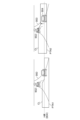
- Figures 1(a) and (b) are diagrams explaining the low beam light distribution of a vehicle lamp.
- Figure 1(a) shows a driving scene on a flat road.
- the low beam is irradiated in a range up to the horizontal direction 804 (strictly speaking, 0.57° downward from the horizontal direction) based on the attitude of the vehicle 800. This ensures visibility ahead of the vehicle while suppressing glare to oncoming vehicles.
- Figure 1(b) shows a driving scene on a slope.
- the vehicle 800 is driving at the start of a slope 806.
- the low beam is irradiated to a range up to the horizontal direction 804 based on the current attitude of the vehicle 800. As the beam does not hit a target 808 on the slope 806, it cannot be said that a sufficient field of vision is ensured.
- FIG. 2 is a diagram illustrating the low beam light distribution pattern at the start of an uphill road 900.
- the light distribution pattern PTN1 on the left of FIG. 2 corresponds to FIG. 1(b).
- the H line corresponds to the horizontal direction 804 based on the attitude of the vehicle 800 in FIG. 1, and the light distribution pattern PTN1 is formed based on this H line.
- the low beam is not irradiated onto the preceding vehicle 902, and sufficient visibility is not ensured.
- the inventor considered shifting the height of the low beam cutoff line CL above the H line at the start of the uphill road 900, as in the light distribution pattern PTN2 on the right in Figure 2.
- the low beam is irradiated to the preceding vehicle 902, ensuring a wide field of vision.
- this light distribution pattern PTN2 has the problem of causing glare when an oncoming vehicle 904 is present near the vehicle.
- FIG. 3 is a diagram illustrating the low beam light distribution pattern at the end of an uphill road 900.
- FIG. 3 shows a low beam light distribution pattern PTN1 based on the H line, which causes glare to an oncoming vehicle 904.
- the light distribution pattern PTN3 on the right side of Figure 3 shifts the height of the low beam cutoff line CL below the H line at the end of the uphill road 900 in order to reduce the glare on the oncoming vehicle 904.
- This light distribution pattern PTN3 can reduce the glare on the oncoming vehicle 904, but it is no longer possible to irradiate the low beam on the leading vehicle 902, reducing visibility.
- the present disclosure has been made in light of the above circumstances, and one of its exemplary objectives is to provide a vehicle lamp that reduces the annoyance felt by humans due to ADB control.
- the present disclosure has also been made in light of the above circumstances, and one of its exemplary objectives is to provide a light distribution that is suitable for driving on slopes.
- An aspect of the present disclosure relates to a vehicle lighting system.
- the vehicle lighting system includes a variable light distribution lamp configured to control the height of a cutoff line of a low beam light distribution, a gaze detection device that detects the gaze direction of a driver, and a controller that changes the height of the cutoff line by controlling the variable light distribution lamp based on the gaze direction detected by the gaze detection device.
- the vehicle lamp includes a patterning device including a plurality of pixels whose luminance can be independently controlled according to an input image, a variable light distribution lamp configured to emit a low beam having a light distribution according to the input image, and a controller that controls the light distribution of the low beam by generating the input image.
- the controller can independently control the height of the cutoff line to the left of the elbow point of the low beam light distribution and the height of the cutoff line to the right of the elbow point according to the driving scene.
- FIG. 1A and 1B are diagrams illustrating low beam light distribution of a vehicle lamp.
- FIG. 13 is a diagram illustrating a light distribution pattern of a low beam at the start point of an uphill road.
- 11 is a diagram illustrating a light distribution pattern of a low beam at the end of an uphill road.
- FIG. FIG. 4 is a block diagram of the lighting system according to the first embodiment.
- 5A and 5B are diagrams for explaining the formation of a low-beam light distribution by the lighting system of FIG. 4 .
- 10A and 10B are diagrams illustrating control of low-beam light distribution based on fluctuations in pitch angle ⁇ p.
- 10A and 10B are diagrams illustrating control of low-beam light distribution based on the line of sight direction ⁇ .
- FIG. 1 is a diagram illustrating gaze control according to a driving scene.
- 1A to 1C are diagrams illustrating an example of gradient detection based on image processing.
- 1A to 1C are diagrams illustrating an example of gradient detection based on image processing.
- FIG. 11 is a block diagram of a lighting system according to a second embodiment.
- FIG. 13 is a diagram showing a light distribution pattern at the start point of an uphill road.
- FIG. 13 is a diagram showing a light distribution pattern at the end point of an uphill road.
- FIG. 13 is a diagram illustrating light distribution control on an uphill road.
- FIG. 13 is a diagram illustrating light distribution control on a downhill road.
- a vehicle lighting system includes a variable light distribution lamp configured to control the height of the cutoff line of a low beam distribution, a gaze detection device that detects the direction of the driver's gaze, and a controller that changes the height of the cutoff line beam by controlling the variable light distribution lamp based on the gaze direction detected by the gaze detection device.
- the driver's line of sight When approaching the start of a slope, the driver's line of sight is directed toward other objects on the slope, so the driver's line of sight is directed slightly upwards relative to the horizontal direction based on the vehicle body. Therefore, by incorporating the line of sight direction into the light distribution control, it becomes possible to project the beam onto other objects on the slope, improving visibility.
- variable light distribution lamp may include a patterning device including a plurality of pixels whose brightness can be independently controlled according to an input image, and may be configured to emit a beam having a light distribution according to the input image.
- the controller may shift the pattern drawn on the input image in the vertical direction based on the line of sight.
- the gaze detection device may include a camera that captures an image of the driver and a processing unit that processes the image from the camera to detect the gaze direction.
- the gaze detection device may include a wearable device that can be worn by a driver and includes at least one sensor, and a processing unit that processes the output of the at least one sensor to detect the gaze direction.
- the controller may enable or disable control of the variable light distribution lamp based on the line of sight depending on the driving scene.
- the controller may enable or disable the control of the variable light distribution lamp based on the line of sight direction depending on whether or not there is a change in the gradient of the road surface. By combining the change in gradient of the road surface with the line of sight direction, more accurate control is possible.
- the vehicle lighting system may further include an inertial sensor capable of detecting the angular velocity and acceleration of a vehicle body on which the vehicle lighting system is mounted.
- the controller may detect the presence or absence of a gradient change according to the output of the inertial sensor.
- the vehicle lighting system may further include a camera that captures an image of the area in front of the vehicle body on which the vehicle lighting system is mounted.
- the controller may detect the presence or absence of a gradient change based on an image from the camera.
- the controller may detect whether or not there is a change in gradient based on the vertical position of the vehicle ahead as seen in the camera image.
- the controller may detect whether or not there is a change in gradient based on the shape of the white line captured in the camera image.
- the controller may detect whether or not there is a change in slope based on map information.
- a vehicle lamp includes a patterning device including a plurality of pixels whose luminance can be independently controlled according to an input image, a variable light distribution lamp configured to emit a low beam having a light distribution according to the input image, and a controller that controls the light distribution of the low beam by generating the input image.
- the controller can independently control the height of the cutoff line to the left of the elbow point of the low beam light distribution and the height of the cutoff line to the right of the elbow point according to the driving scene.
- This configuration reduces glare for oncoming vehicles while brightening the field of view ahead of the vehicle.
- the controller may increase the height of the cutoff line on the side of the own lane from the elbow point at the start of an uphill section while maintaining the height of the cutoff line on the oncoming lane side from the elbow point.
- the controller may increase the height of the cutoff line on the side of the own lane from the elbow point at the end of the downhill road while maintaining the height of the cutoff line on the oncoming lane side from the elbow point.
- the controller may increase the height of the cutoff line on the oncoming lane side from the elbow point at the end of the uphill section while maintaining the height of the cutoff line on the own lane side from the elbow point.
- the controller may increase the height of the cutoff line on the oncoming lane side from the elbow point at the start of a downhill road while maintaining the height of the cutoff line on the own lane side from the elbow point.
- the low beam light distribution may be Z-shaped.
- the controller may be capable of independently controlling the height of the right horizontal cut-off line to the right of the elbow point and the height of the left horizontal cut-off line on the vehicle's lane side from the elbow point.
- the controller may increase the height of the left horizontal cutoff line at the start of an uphill section while maintaining the height of the right horizontal cutoff line.
- the controller may increase the height of the left horizontal cutoff line at the end of the downhill section while maintaining the height of the right horizontal cutoff line.
- the controller may lower the height of the right horizontal cutoff line at the end of an uphill section while maintaining the height of the left horizontal cutoff line.
- the controller may lower the height of the right horizontal cutoff line at the start of a downhill section while maintaining the height of the left horizontal cutoff line.
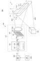
- (Embodiment 1) 4 is a block diagram of the lighting system 200 according to the embodiment 1.
- the lighting system 200 is a headlamp mounted on an automobile for illuminating the field of view ahead of the vehicle, and forms at least a low beam light distribution.
- the lighting system 200 includes a vehicle lighting device 100, a vehicle ECU (Electronic Control Unit) 202, an attitude sensor 206, and a gaze detection device 208.
- vehicle lighting device 100 a vehicle ECU (Electronic Control Unit) 202
- attitude sensor 206 an attitude sensor
- gaze detection device 208 an attitude sensor
- the attitude sensor 206 is configured to detect the inclination of the vehicle body in the pitching direction (pitch angle ⁇ p).
- the attitude sensor 206 is, for example, a gyro sensor.
- the gaze detection device 208 is configured to be able to detect the direction of the driver's gaze.
- the gaze detection device 208 may include a camera installed inside the vehicle cabin and a calculation processing unit that processes the image from the camera. By monitoring the driver's head with the camera, the gaze direction can be estimated by image processing.
- a driver monitoring system may be installed in the vehicle cabin to monitor the driver's sleep, fatigue, or injuries.
- the drive recorder may be equipped with a camera that records images inside the vehicle cabin. In these cases, the gaze direction may be detected using these cameras.
- the gaze detection device 208 may include a wearable device that can be worn by the driver and includes at least one sensor, and a processing unit that processes the output of the at least one sensor to detect the gaze direction.
- a wearable device is AR (Augmented Reality) glasses.
- the attitude sensor 206 and the gaze detection device 208 are connected to the vehicle ECU 202.
- the vehicle ECU 202 and the vehicle lamp 100 are connected via a vehicle bus such as CAN (Controller Area Network) or LIN (Local Interconnect Network).
- the vehicle ECU 202 transmits information (attitude information) S1 indicating the pitch angle ⁇ p detected by the attitude sensor 206 and information (gaze information) S2 indicating the gaze direction ⁇ detected by the gaze detection device 208 to the vehicle lamp 100.
- the vehicle lamp 100 is equipped with a variable light distribution lamp 110 and a fixed light distribution lamp 150, and the combination of the two lamps forms a low beam light distribution.
- the fixed light distribution lamp 150 is optional, and the low beam light distribution may be formed by the variable light distribution lamp 110 alone.
- FIG. 4 shows a virtual vertical screen 2, on which a low beam light distribution 4 is shown in schematic form.
- the variable light distribution lamp 110 covers a rectangular area 10 shown by a dashed line.
- This rectangular area 10 is the area in which a high beam light distribution should be formed.
- the upper first portion 6 including the cutoff line CL is included in this rectangular area 10.
- the cutoff line CL includes a horizontal cutoff line CLa and an oblique cutoff line CLb, which intersect at the elbow point LB.
- the fixed light distribution lamp 150 irradiates the second portion 8, which includes the lower end of the low beam light distribution 4, with the second beam BM2.
- the second portion 8 is called a diffuse low beam light distribution. The first portion 6 and the second portion 8 overlap.
- the variable light distribution lamp 110 is configured so that the height of the cutoff line of the low beam distribution can be controlled.
- the height of the cutoff line of the low beam distribution can be understood as the emission direction of the low beam in relation to the vertical direction H.
- the variable light distribution lamp 110 includes a high-definition lamp unit 120 and a controller 130.
- the high-definition lamp unit 120 includes a light-emitting element array 122 and an irradiation optical system 124.
- the light-emitting element array 122 includes a plurality of pixels PIX arranged in a matrix, and the brightness of each pixel PIX can be independently controlled in multiple gradations according to the input image IMG.
- An LED array can be used as the light-emitting element array 122.
- the controller 130 generates an input image IMG that defines the brightness of multiple pixels PIX of the light-emitting element array 122 and supplies it to the high-definition lamp unit 120.
- the projection optical system 124 projects the output light of the light-emitting element array 122 forward of the vehicle.
- the projection optical system 124 may be a lens optical system, a reflective optical system, or a combination of both.
- the correspondence between the position of a pixel and the corresponding irradiation area on the virtual vertical screen 2 is determined by the irradiation optical system 124, and may be a mirror image (left-right inversion), up-down inversion, or up-down-left-right inversion.
- the controller 130 controls the on/off of the multiple pixels 112 of the light-emitting element array 122 so that the first portion 6 below the cutoff line CL is illuminated on the virtual vertical screen 2. Specifically, the controller 130 turns on the pixels below (or above) the line 126 that corresponds to the cutoff line, and turns off the pixels above (or below) it.
- variable light distribution lamp 110 can change the height of the cutoff line vertically by shifting the boundary line 126 between the on area and the off area vertically on the input image IMG.
- FIG. 5 is a diagram illustrating the formation of the low beam light distribution 4 by the lighting system 200 of FIG. 4.
- a rectangular area 10 indicates the range that can be illuminated by the variable light distribution lamp 110, and is divided into a number of meshes (sub-areas) 12 corresponding to a number of pixels PIX.
- the illuminance of each mesh 12 corresponds to the luminance of the corresponding pixel PIX.
- a pixel PIX being off is not limited to a case where the luminance is zero, i.e., the illuminance of the corresponding mesh 12 is zero, but can also include a case where the luminance is very low, i.e., the illuminance of the corresponding mesh 12 is not zero but is very low.
- the controller 130 generates the input image IMG so that pixels corresponding to the mesh 12 above the cutoff line CL are turned off and pixels corresponding to the mesh 12 below the cutoff line CL are turned on.
- the controller 130 includes an interface circuit 132 and an arithmetic processing unit 134.
- the interface circuit 132 receives attitude information S1 and line of sight information S2 via the vehicle bus.
- the arithmetic processing unit 134 of the controller 130 dynamically controls the emission direction of the low beam, in other words, the height of the cut-off line CL, based on the attitude information S1 and line of sight information S2.
- the arithmetic processing unit 134 can be implemented as a combination of hardware such as a microcontroller or a CPU and a software program.
- the controller 130 generates the input image IMG based on the attitude information S1, i.e., the pitch angle ⁇ p, so that the height of the cutoff line from the road surface remains constant regardless of changes in the attitude of the vehicle body.
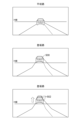
- Figure 6 is a diagram explaining the control of low beam light distribution 4 based on fluctuations in pitch angle ⁇ p.
- the left side of Figure 6 shows low beam light distribution 4a when the vehicle body 30 is in a nose-up state ( ⁇ p>0°).
- the right side of Figure 6 shows low beam light distribution 4c when the vehicle body 30 is in a nose-dive state ( ⁇ p ⁇ 0°). 0° indicates the angle horizontal to the road surface.
- the shading in the figure represents the illuminance of each mesh.
- the second portion 8 formed by the fixed light distribution lamp 150 moves up and down relative to the horizontal 0° when the pitch angle ⁇ p changes.
- the position of the boundary between the on-pixel region and the off-pixel region of the multiple pixels PIX is controlled so that the height of the cutoff line CL of the first portion 6 formed by the variable light distribution lamp 110 is maintained near the horizontal 0° (specifically, -0.57°) even when the pitch angle ⁇ p changes.
- the height of the cutoff line CL is controlled to remain substantially horizontal even when the vehicle body is in a nose-up or nose-dive position. This provides the driver with good visibility.
- the above control is mainly effective on flat roads.
- the controller 130 controls the height of the cutoff line of the low beam distribution based on the line-of-sight information S2, i.e., the line-of-sight direction ⁇ (this is called line-of-sight control).
- FIG. 7 is a diagram explaining the control of the low beam light distribution 4 based on the line of sight direction ⁇ .
- the line of sight direction ⁇ is set to 0 in the horizontal direction, positive in the upward direction, and negative in the downward direction.
- the driver's line of sight when driving on a normal flat road, the driver's line of sight is directed toward the vanishing point, and the line of sight direction ⁇ is essentially zero.
- the driver's line of sight At the start of an uphill road, as shown on the right side of Figure 7, the driver's line of sight is directed upward, and the line of sight direction ⁇ is positive.
- the driver's line of sight is directed downward, and the line of sight direction ⁇ is negative.
- the low beam can be directed at targets on an uphill road, improving visibility.
- the height of the cutoff line may be controlled based on the signal after applying a moving average filter or low-pass filter to the line of sight direction ⁇ , for example.
- the controller 130 may switch between enabling and disabling gaze control depending on the driving scene. Specifically, the controller 130 may determine whether or not it is near the start and/or end of a slope, and enable gaze control only when it is determined that it is near the start and/or end of a slope.
- FIG. 8 is a diagram explaining gaze control according to the driving scene. Gaze control is disabled where the gradient is constant, such as road surface 900 and road surface 904, but gaze control is enabled on road surface 902, where the gradient changes.
- the method for detecting whether or not there is a change in gradient is not particularly limited, but several methods will be described as examples.
- the presence or absence of a gradient change may be determined based on the output of an inertial sensor capable of detecting the angular velocity and acceleration of the vehicle body on which the vehicle lamp 100 is mounted. Specifically, when the angular velocity ⁇ is smaller than a predetermined threshold value, it may be determined that there is no gradient change and line of sight control may be disabled. Conversely, when the angular velocity ⁇ is greater than the threshold value, it may be determined that there is a gradient change and line of sight control may be enabled.
- This inertial sensor may be the attitude sensor 206 in FIG. 4.
- gaze control may be disabled. Conversely, gaze control may be enabled when a change in the direction of the motion vector is detected.
- the presence or absence of gradient changes can be detected by image processing.
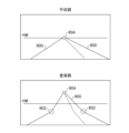
- FIG. 9 is a diagram illustrating an example of gradient detection based on image processing.
- FIG. 9 shows an image captured on a flat road and an image captured just before an uphill road.
- the vehicle ahead 500 i.e., the preceding vehicle or an oncoming vehicle
- the relative positional relationship in the vertical direction between the H line and the vehicle ahead 500 changes. This property can be used to detect gradient changes.
- gradient change detection can be achieved by a camera and a processor that processes the image from the camera.
- the camera captures an image in front of the vehicle.
- the processor may be the processor 134 of the controller 130 in FIG. 1, or it may be hardware on the vehicle side.
- the calculation processing unit may analyze the camera image and determine that there is a gradient change if the vehicle ahead 500 is above the H line (vertical 0°) and enable line of sight control.
- the calculation processing unit may determine that there is a change in gradient and enable line of sight control.
- FIG. 10 is a diagram illustrating one embodiment of gradient detection based on image processing.
- FIG. 10 shows an image captured on a flat road and an image captured just before an uphill road.
- the presence or absence of a gradient change can be detected based on the shape of the white line 600. That is, on a flat road, the white line 600 can be considered to be substantially a straight line.
- the white line 600 can be considered to be substantially a straight line.
- the presence or absence of the bend 602 can be detected by image processing, and if the bend 602 is detected, it can be determined that there is a gradient change.
- the position of the white line 600 in the image remains roughly constant.
- the position of the white line 600 shifts from its position on the flat road. Therefore, the presence or absence of a change in gradient may be determined based on the position of the white line 600 through image processing.
- the vanishing point 604 is located near the H-line.
- the vanishing point 604 is located at a position vertically away from the H-line.
- the vanishing point 604 can be detected by image processing, and it can be determined whether the position of the vanishing point 604 has deviated from the position of the vanishing point on a flat road, and if so, it can be determined that there is a change in gradient.
- the vanishing point can also be detected by extending the white line 600.
- the position of the vanishing point may be detected using techniques such as optical flow without using white lines.
- the presence or absence of a change in gradient may be detected based on map information contained in the vehicle's car navigation system or map information stored on an external server.
- (Embodiment 2) 11 is a block diagram of a lighting system 200 according to embodiment 2.
- the lighting system 200 is a headlamp mounted on an automobile for illuminating the field of view ahead of the vehicle, and forms at least a low beam light distribution.
- the lighting system 200 includes a vehicle lighting device 100, a vehicle ECU (Electronic Control Unit) 202, and an attitude sensor 206.
- vehicle lighting device 100 a vehicle lighting device 100
- vehicle ECU Electronic Control Unit
- attitude sensor 206 an attitude sensor
- the attitude sensor 206 is configured to detect the inclination of the vehicle body in the pitching direction (pitch angle ⁇ p).
- the attitude sensor 206 is, for example, a gyro sensor.
- the attitude sensor 206 is connected to the vehicle ECU 202.
- the vehicle ECU 202 and the vehicle lamp 100 are connected via a vehicle bus such as a Controller Area Network (CAN) or a Local Interconnect Network (LIN).
- the vehicle ECU 202 transmits information (attitude information) S1 indicating the pitch angle ⁇ p detected by the attitude sensor 206 to the vehicle lamp 100.
- the vehicle lamp 100 is equipped with a variable light distribution lamp 110 and a fixed light distribution lamp 150, and forms a low beam light distribution by combining the two lamps.
- the fixed light distribution lamp 150 is optional, and the low beam light distribution may be formed by the variable light distribution lamp 110 alone.
- FIG. 11 shows a virtual vertical screen 2, on which a low beam light distribution 4 is shown in schematic form.
- the variable light distribution lamp 110 covers a rectangular area 10 shown by a dashed dotted line.
- This rectangular area 10 is the area in which a high beam light distribution should be formed.
- the upper first portion 6 including the cutoff line CL is included in this rectangular area 10.
- the low beam light distribution 4 is Z-shaped, and the cutoff line CL includes a right horizontal cutoff line CLa, a diagonal cutoff line CLb, and a left horizontal cutoff line CLc.
- the fixed light distribution lamp 150 irradiates the second portion 8, which includes the lower end of the low beam light distribution 4, with the second beam BM2.
- the second portion 8 is called a diffuse low beam light distribution. The first portion 6 and the second portion 8 overlap.
- the variable light distribution lamp 110 is configured to emit a low beam having a light distribution according to the input image IMG.
- the variable light distribution lamp 110 includes a high-definition lamp unit 120 and a controller 130.
- the high-definition lamp unit 120 includes a light-emitting element array 122 and an irradiation optical system 124.
- the light-emitting element array 122 includes a plurality of pixels PIX arranged in a matrix, and the brightness of each pixel PIX can be independently controlled in multiple gradations according to the input image IMG.
- An LED array can be used as the light-emitting element array 122.
- the controller 130 generates an input image IMG that defines the brightness of multiple pixels PIX of the light-emitting element array 122 and supplies it to the high-definition lamp unit 120.
- the projection optical system 124 projects the output light of the light-emitting element array 122 forward of the vehicle.
- the projection optical system 124 may be a lens optical system, a reflective optical system, or a combination of both.
- the correspondence between the position of a pixel and the corresponding irradiation area on the virtual vertical screen 2 is determined by the irradiation optical system 124, and may be a mirror image (left-right inversion), up-down inversion, or up-down-left-right inversion.
- the controller 130 controls the on/off of the multiple pixels 112 of the light-emitting element array 122 so that the first portion 6 below the cutoff line CL is illuminated on the virtual vertical screen 2. Specifically, the controller 130 turns on the pixels below (or above) the line 126 that corresponds to the cutoff line, and turns off the pixels above (or below) it.
- variable light distribution lamp 110 can change the height of the cutoff line vertically by shifting the boundary line 126 between the on area and the off area vertically on the input image IMG.
- the formation of the low beam light distribution 4 by the lighting system 200 in FIG. 11 is similar to that in the first embodiment described with reference to FIG. 5, so a duplicated description will be omitted.
- the controller 130 includes an interface circuit 132 and an arithmetic processing unit 134.
- the interface circuit 132 receives attitude information S1 via the vehicle bus.
- the arithmetic processing unit 134 of the controller 130 dynamically controls the emission direction of the low beam, in other words, the height of the cutoff line CL, based on the attitude information S1.
- the arithmetic processing unit 134 can be implemented as a combination of hardware such as a microcontroller or a CPU and a software program.
- the controller 130 generates the input image IMG based on the attitude information S1, i.e., the pitch angle ⁇ p, so that the height of the cutoff line from the road surface remains constant regardless of changes in the attitude of the vehicle body.
- the control of the low beam light distribution 4 based on the variation of the pitch angle ⁇ p is the same as that described in the first embodiment with reference to FIG. 6, so a duplicated explanation will be omitted.
- the above control is mainly effective on flat roads.
- the controller 130 controls the height of the cutoff line of the low beam distribution depending on the driving scene. More specifically, the controller 130 independently controls the height of the cutoff line (left horizontal cutoff line) CLc to the left of the elbow point LB of the low beam distribution and the height of the cutoff line (right horizontal cutoff line) CLa to the right of the elbow point LB depending on the driving scene.
- the explanation is based on the assumption that the country or region drives on the left side, such as Japan.
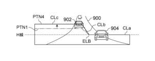
- FIG. 12 is a diagram showing a light distribution pattern PTN4 at the start of an uphill road 900.
- FIG. 12 also shows a normal light distribution pattern PTN1.
- the controller 130 increases the height of the left horizontal cutoff line CLc on the own lane side of the elbow point LB while maintaining the height of the right horizontal cutoff line CLa on the oncoming lane side of the elbow point LB, compared to the normal light distribution pattern PTN1.
- This light distribution control allows the beam to be directed at the preceding vehicle 902 while suppressing the glare given to the oncoming vehicle 904.
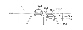
- FIG. 13 is a diagram showing a light distribution pattern PTN5 at the end of an uphill road. For comparison, FIG. 13 also shows a normal light distribution pattern PTN1.
- the controller 130 When approaching the end of the uphill road 900, the controller 130 lowers the height of the right horizontal cutoff line CLa while maintaining the height of the left horizontal cutoff line CLc, relative to the normal light distribution pattern PTN1.
- This light distribution control allows the beam to be directed at the preceding vehicle 902 while suppressing the glare given to the oncoming vehicle 904.
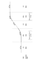
- Figure 14 is a diagram explaining light distribution control on an uphill road. Independent control of the left and right cutoff lines is effective at the start and end points of the uphill road.
- independent light distribution control for the left and right can be applied on downhill roads in the same way, in addition to or instead of on uphill roads.
- FIG. 15 is a diagram explaining light distribution control on a downhill road. Independent control of the left and right cutoff lines is effective at the start and end of the downhill road. Specifically, at the start of the downhill road, the controller 130 may lower the height of the right horizontal cutoff line CLa while maintaining the height of the left horizontal cutoff line CLc. Also, at the end of the downhill road, the controller 130 may increase the height of the left horizontal cutoff line CLc while maintaining the height of the right horizontal cutoff line CLa.
- the Z-shaped light distribution will be a shape that is reversed from left to right from that explained in the embodiment, with the right side of the elbow point LB being the own vehicle lane and the left side of the elbow point LB being the oncoming vehicle lane.
- the controller 130 may detect the start and end points of an uphill road or a downhill road by monitoring the change in gradient.
- Any of the methods described in embodiment 1 can be used to detect whether or not there is a change in gradient.
- attitude sensor 206 In the embodiment, a gyro sensor is used as the attitude sensor 206, but the present disclosure is not limited to this, and the attitude sensor 206 may be a pair of vehicle height sensors attached to the front and rear of the vehicle body.
- the high-definition lamp unit 120 may be a combination of a light source and a DMD (Digital Mirror Device) that patterns the light emitted from the light source.
- the high-definition lamp unit 120 may be a combination of a light source and a liquid crystal device that patterns the light emitted from the light source.
- a Z-shaped low beam distribution has been described, but the present disclosure is not limited to this and can also be applied to a low beam distribution consisting of a right horizontal cutoff line and a diagonal cutoff line.
- This disclosure relates to vehicle lighting.
- 200 lighting system, 202...vehicle ECU, 206...attitude sensor, 208...gaze detection device, 100...vehicle lamp, 110...variable light distribution lamp, 120...high-definition lamp unit, 122...light-emitting element array, 124...illumination optical system, 130...controller, 132...interface circuit, 134...arithmetic processing unit, 150...fixed light distribution lamp, BM1...first beam, BM2...second beam, 6...first portion, 8...second portion, 2...virtual vertical screen, S1...attitude information, S2...gaze information.
Landscapes
- Engineering & Computer Science (AREA)
- Mechanical Engineering (AREA)
- Lighting Device Outwards From Vehicle And Optical Signal (AREA)
Priority Applications (4)
| Application Number | Priority Date | Filing Date | Title |
|---|---|---|---|
| CN202480011979.4A CN120677087A (zh) | 2023-02-17 | 2024-02-15 | 车辆用灯具系统、配光可变灯的控制器、控制方法、程序 |
| EP24756965.0A EP4667285A1 (en) | 2023-02-17 | 2024-02-15 | Vehicle lighting system, controller for variable light distribution lamp, control method, and program |
| JP2025501213A JPWO2024172125A1 (https=) | 2023-02-17 | 2024-02-15 | |
| US19/301,496 US20250376105A1 (en) | 2023-02-17 | 2025-08-15 | Vehicle lamp system |
Applications Claiming Priority (4)
| Application Number | Priority Date | Filing Date | Title |
|---|---|---|---|
| JP2023-023764 | 2023-02-17 | ||
| JP2023023763 | 2023-02-17 | ||
| JP2023023764 | 2023-02-17 | ||
| JP2023-023763 | 2023-02-17 |
Related Child Applications (1)
| Application Number | Title | Priority Date | Filing Date |
|---|---|---|---|
| US19/301,496 Continuation US20250376105A1 (en) | 2023-02-17 | 2025-08-15 | Vehicle lamp system |
Publications (1)
| Publication Number | Publication Date |
|---|---|
| WO2024172125A1 true WO2024172125A1 (ja) | 2024-08-22 |
Family
ID=92420016
Family Applications (1)
| Application Number | Title | Priority Date | Filing Date |
|---|---|---|---|
| PCT/JP2024/005312 Ceased WO2024172125A1 (ja) | 2023-02-17 | 2024-02-15 | 車両用灯具システム、配光可変ランプのコントローラ、制御方法、プログラム |
Country Status (5)
| Country | Link |
|---|---|
| US (1) | US20250376105A1 (https=) |
| EP (1) | EP4667285A1 (https=) |
| JP (1) | JPWO2024172125A1 (https=) |
| CN (1) | CN120677087A (https=) |
| WO (1) | WO2024172125A1 (https=) |
Cited By (1)
| Publication number | Priority date | Publication date | Assignee | Title |
|---|---|---|---|---|
| CN119189858A (zh) * | 2024-10-08 | 2024-12-27 | 广州汽车集团股份有限公司 | 车辆及其灯光截止线调节方法、灯光截止线调节装置 |
Citations (7)
| Publication number | Priority date | Publication date | Assignee | Title |
|---|---|---|---|---|
| JP2000233684A (ja) * | 1999-02-16 | 2000-08-29 | Nissan Motor Co Ltd | 自動車用の前照灯配光制御装置 |
| JP2005259501A (ja) * | 2004-03-11 | 2005-09-22 | Ichikoh Ind Ltd | ヘッドランプ |
| JP2021020532A (ja) * | 2019-07-26 | 2021-02-18 | 株式会社小糸製作所 | 車両用灯具 |
| WO2021182151A1 (ja) | 2020-03-10 | 2021-09-16 | 株式会社小糸製作所 | 車両用前照灯 |
| WO2021200701A1 (ja) | 2020-03-31 | 2021-10-07 | 株式会社小糸製作所 | 車両用前照灯 |
| WO2022085683A1 (ja) * | 2020-10-20 | 2022-04-28 | 株式会社小糸製作所 | 車両用灯具システム、配光制御装置および配光制御方法 |
| WO2022270415A1 (ja) * | 2021-06-22 | 2022-12-29 | 株式会社小糸製作所 | 配光コントローラおよび車両用灯具システム |
-
2024
- 2024-02-15 JP JP2025501213A patent/JPWO2024172125A1/ja active Pending
- 2024-02-15 CN CN202480011979.4A patent/CN120677087A/zh active Pending
- 2024-02-15 EP EP24756965.0A patent/EP4667285A1/en active Pending
- 2024-02-15 WO PCT/JP2024/005312 patent/WO2024172125A1/ja not_active Ceased
-
2025
- 2025-08-15 US US19/301,496 patent/US20250376105A1/en active Pending
Patent Citations (7)
| Publication number | Priority date | Publication date | Assignee | Title |
|---|---|---|---|---|
| JP2000233684A (ja) * | 1999-02-16 | 2000-08-29 | Nissan Motor Co Ltd | 自動車用の前照灯配光制御装置 |
| JP2005259501A (ja) * | 2004-03-11 | 2005-09-22 | Ichikoh Ind Ltd | ヘッドランプ |
| JP2021020532A (ja) * | 2019-07-26 | 2021-02-18 | 株式会社小糸製作所 | 車両用灯具 |
| WO2021182151A1 (ja) | 2020-03-10 | 2021-09-16 | 株式会社小糸製作所 | 車両用前照灯 |
| WO2021200701A1 (ja) | 2020-03-31 | 2021-10-07 | 株式会社小糸製作所 | 車両用前照灯 |
| WO2022085683A1 (ja) * | 2020-10-20 | 2022-04-28 | 株式会社小糸製作所 | 車両用灯具システム、配光制御装置および配光制御方法 |
| WO2022270415A1 (ja) * | 2021-06-22 | 2022-12-29 | 株式会社小糸製作所 | 配光コントローラおよび車両用灯具システム |
Cited By (1)
| Publication number | Priority date | Publication date | Assignee | Title |
|---|---|---|---|---|
| CN119189858A (zh) * | 2024-10-08 | 2024-12-27 | 广州汽车集团股份有限公司 | 车辆及其灯光截止线调节方法、灯光截止线调节装置 |
Also Published As
| Publication number | Publication date |
|---|---|
| EP4667285A1 (en) | 2025-12-24 |
| CN120677087A (zh) | 2025-09-19 |
| US20250376105A1 (en) | 2025-12-11 |
| JPWO2024172125A1 (https=) | 2024-08-22 |
Similar Documents
| Publication | Publication Date | Title |
|---|---|---|
| US11704910B2 (en) | Vehicle detecting device and vehicle lamp system | |
| CN101190664B (zh) | 车辆照明系统 | |
| JP2017206094A (ja) | 車両用灯具 | |
| CN110300683A (zh) | 机动车前照灯的控制 | |
| JP2011037342A (ja) | 車両用前照灯システム | |
| JP2021088233A (ja) | 車両用投光制御装置、車両用投光システム、及び車両用投光制御方法 | |
| JP2013097885A (ja) | ヘッドライト装置、及びヘッドライトシステム | |
| US20250376105A1 (en) | Vehicle lamp system | |
| JP5547580B2 (ja) | 撮像カメラ及びこれを用いた車両検出装置とランプ制御装置 | |
| JP2011253222A (ja) | 前方領域検出装置及び車両制御装置 | |
| CN110774976B (zh) | 用于控制车辆前灯的装置和方法 | |
| WO2022196296A1 (ja) | 車両用灯具の制御装置、車両用灯具の制御方法、車両用灯具システム | |
| CN118804853A (zh) | 灯系统、灯控制方法、灯控制程序以及车辆 | |
| JP2019219816A (ja) | 画像処理装置および車両用灯具 | |
| US20250326350A1 (en) | Vehicle lamp apparatus | |
| CN111278679A (zh) | 车辆照明控制方法和车辆照明控制设备 | |
| JP2018122736A (ja) | 車両用照明の表示方法及び表示制御装置 | |
| CN209776290U (zh) | 车辆检测装置以及车辆用灯具系统 | |
| JP7398287B2 (ja) | 車両用灯具 | |
| JP7754112B2 (ja) | 配光制御装置 | |
| JP2003054311A (ja) | 車両用前照灯制御装置 | |
| CN112240529B (zh) | 配光控制装置以及车辆用灯具系统 | |
| WO2025159052A1 (ja) | 配光可変ランプの制御装置、車両用灯具、ソフトウェアプログラム | |
| WO2025249124A1 (ja) | 制御装置、車両用灯具システム、およびソフトウェアプログラム | |
| WO2024190568A1 (ja) | 配光可変ランプの制御装置、車両用灯具、ソフトウェアプログラム |
Legal Events
| Date | Code | Title | Description |
|---|---|---|---|
| 121 | Ep: the epo has been informed by wipo that ep was designated in this application |
Ref document number: 24756965 Country of ref document: EP Kind code of ref document: A1 |
|
| ENP | Entry into the national phase |
Ref document number: 2025501213 Country of ref document: JP Kind code of ref document: A |
|
| WWE | Wipo information: entry into national phase |
Ref document number: 2025501213 Country of ref document: JP |
|
| WWE | Wipo information: entry into national phase |
Ref document number: 202480011979.4 Country of ref document: CN |
|
| WWE | Wipo information: entry into national phase |
Ref document number: 2024756965 Country of ref document: EP |
|
| NENP | Non-entry into the national phase |
Ref country code: DE |
|
| WWP | Wipo information: published in national office |
Ref document number: 202480011979.4 Country of ref document: CN |
|
| ENP | Entry into the national phase |
Ref document number: 2024756965 Country of ref document: EP Effective date: 20250917 |
|
| WWP | Wipo information: published in national office |
Ref document number: 2024756965 Country of ref document: EP |