WO2024172064A1 - 電池用緩衝構造 - Google Patents
電池用緩衝構造 Download PDFInfo
- Publication number
- WO2024172064A1 WO2024172064A1 PCT/JP2024/004981 JP2024004981W WO2024172064A1 WO 2024172064 A1 WO2024172064 A1 WO 2024172064A1 JP 2024004981 W JP2024004981 W JP 2024004981W WO 2024172064 A1 WO2024172064 A1 WO 2024172064A1
- Authority
- WO
- WIPO (PCT)
- Prior art keywords
- cushioning
- battery
- protrusion
- sheet
- cushioning structure
- Prior art date
- Legal status (The legal status is an assumption and is not a legal conclusion. Google has not performed a legal analysis and makes no representation as to the accuracy of the status listed.)
- Ceased
Links
Images



Classifications
-
- H—ELECTRICITY
- H01—ELECTRIC ELEMENTS
- H01M—PROCESSES OR MEANS, e.g. BATTERIES, FOR THE DIRECT CONVERSION OF CHEMICAL ENERGY INTO ELECTRICAL ENERGY
- H01M50/00—Constructional details or processes of manufacture of the non-active parts of electrochemical cells other than fuel cells, e.g. hybrid cells
- H01M50/20—Mountings; Secondary casings or frames; Racks, modules or packs; Suspension devices; Shock absorbers; Transport or carrying devices; Holders
- H01M50/233—Mountings; Secondary casings or frames; Racks, modules or packs; Suspension devices; Shock absorbers; Transport or carrying devices; Holders characterised by physical properties of casings or racks, e.g. dimensions
- H01M50/242—Mountings; Secondary casings or frames; Racks, modules or packs; Suspension devices; Shock absorbers; Transport or carrying devices; Holders characterised by physical properties of casings or racks, e.g. dimensions adapted for protecting batteries against vibrations, collision impact or swelling
-
- H—ELECTRICITY
- H01—ELECTRIC ELEMENTS
- H01M—PROCESSES OR MEANS, e.g. BATTERIES, FOR THE DIRECT CONVERSION OF CHEMICAL ENERGY INTO ELECTRICAL ENERGY
- H01M10/00—Secondary cells; Manufacture thereof
- H01M10/60—Heating or cooling; Temperature control
- H01M10/64—Heating or cooling; Temperature control characterised by the shape of the cells
- H01M10/647—Prismatic or flat cells, e.g. pouch cells
-
- H—ELECTRICITY
- H01—ELECTRIC ELEMENTS
- H01M—PROCESSES OR MEANS, e.g. BATTERIES, FOR THE DIRECT CONVERSION OF CHEMICAL ENERGY INTO ELECTRICAL ENERGY
- H01M10/00—Secondary cells; Manufacture thereof
- H01M10/60—Heating or cooling; Temperature control
- H01M10/65—Means for temperature control structurally associated with the cells
- H01M10/658—Means for temperature control structurally associated with the cells by thermal insulation or shielding
-
- H—ELECTRICITY
- H01—ELECTRIC ELEMENTS
- H01M—PROCESSES OR MEANS, e.g. BATTERIES, FOR THE DIRECT CONVERSION OF CHEMICAL ENERGY INTO ELECTRICAL ENERGY
- H01M50/00—Constructional details or processes of manufacture of the non-active parts of electrochemical cells other than fuel cells, e.g. hybrid cells
- H01M50/20—Mountings; Secondary casings or frames; Racks, modules or packs; Suspension devices; Shock absorbers; Transport or carrying devices; Holders
- H01M50/204—Racks, modules or packs for multiple batteries or multiple cells
-
- H—ELECTRICITY
- H01—ELECTRIC ELEMENTS
- H01M—PROCESSES OR MEANS, e.g. BATTERIES, FOR THE DIRECT CONVERSION OF CHEMICAL ENERGY INTO ELECTRICAL ENERGY
- H01M50/00—Constructional details or processes of manufacture of the non-active parts of electrochemical cells other than fuel cells, e.g. hybrid cells
- H01M50/20—Mountings; Secondary casings or frames; Racks, modules or packs; Suspension devices; Shock absorbers; Transport or carrying devices; Holders
- H01M50/289—Mountings; Secondary casings or frames; Racks, modules or packs; Suspension devices; Shock absorbers; Transport or carrying devices; Holders characterised by spacing elements or positioning means within frames, racks or packs
- H01M50/291—Mountings; Secondary casings or frames; Racks, modules or packs; Suspension devices; Shock absorbers; Transport or carrying devices; Holders characterised by spacing elements or positioning means within frames, racks or packs characterised by their shape
-
- Y—GENERAL TAGGING OF NEW TECHNOLOGICAL DEVELOPMENTS; GENERAL TAGGING OF CROSS-SECTIONAL TECHNOLOGIES SPANNING OVER SEVERAL SECTIONS OF THE IPC; TECHNICAL SUBJECTS COVERED BY FORMER USPC CROSS-REFERENCE ART COLLECTIONS [XRACs] AND DIGESTS
- Y02—TECHNOLOGIES OR APPLICATIONS FOR MITIGATION OR ADAPTATION AGAINST CLIMATE CHANGE
- Y02E—REDUCTION OF GREENHOUSE GAS [GHG] EMISSIONS, RELATED TO ENERGY GENERATION, TRANSMISSION OR DISTRIBUTION
- Y02E60/00—Enabling technologies; Technologies with a potential or indirect contribution to GHG emissions mitigation
- Y02E60/10—Energy storage using batteries
Definitions
- the present invention relates to a cushioning structure for batteries.
- the quality can deteriorate due to the expansion and contraction of the cells.
- the cells will expand and contract during charging and discharging, which will place a strain on the electrode particles, causing them to break and shortening the battery's lifespan.
- variations in surface pressure caused by expansion and contraction lead to variations in performance and also affect the battery's lifespan. For this reason, a technology is known in which cushioning materials are provided between adjacent cells, or between the cells and the housing or supporting members, to reduce stress on the cells.
- the cushioning material is a flat plate, when it is compressed, the reaction force increases suddenly even at a low compression rate, and sufficient cushioning effect cannot be obtained. Also, if the cushioning material is a flat plate with multiple protrusions, stress is concentrated at the points where the protrusions come into contact, raising concerns about a decrease in battery performance. As such, there is still room for improvement.
- the present invention provides a cushioning structure for batteries that can improve the cushioning function.
- the present invention employs the following measures to solve the above problems.
- the cushioning structure for a battery of the present invention is A buffer sheet; a heat insulating member disposed between the buffer sheet and the battery component; A cushioning structure for a battery comprising:
- the buffer sheet is characterized by having a protruding portion that protrudes toward the insulating member.
- an insulating member is provided between the buffer sheet and the battery components (cells, housing, support members, etc.), stress caused by protrusions provided on the buffer sheet is dispersed by the insulating member. This makes it possible to suppress the concentration of stress on the battery components due to the protrusions.
- an insulating member is provided between the buffer sheet and the battery components in the present invention, the propagation of heat can be suppressed.
- the cushioning structure for a battery of the present invention is A buffer sheet; An interposing member; A cushioning structure for a battery comprising: The buffer sheet includes a protruding portion protruding toward the intermediate member, The intermediate member has a stress dispersion function for dispersing stress caused by the protrusion.
- the stress concentration on the battery components due to the protrusions can be suppressed by using an intervening member that has a stress dispersion function that disperses the stress caused by the protrusions.
- the cushioning structure for a battery of another invention is A buffer sheet; An interposing member; A cushioning structure for a battery comprising:
- the buffer sheet includes a protruding portion protruding toward an opposite side to the intermediate member,
- the present invention is characterized in that when the cushioning structure for a battery is compressed until the maximum thickness of the cushioning sheet in the protruding direction of the protrusion is halved when no external force is acting on the cushioning structure for a battery, the back side of the most distal end of the protrusion does not come into contact with the interposing member and a space is maintained between the protrusion and the interposing member.
- the cushioning structure for batteries is compressed until the maximum thickness of the cushioning sheet in the protruding direction of the protrusion is halved, a space is maintained between the protrusion and the interposing member, so that a sudden increase in the repulsive force of the cushioning structure for batteries can be suppressed.
- the air in the space has the effect of maintaining the insulating function.
- the protrusions provided on one side of the buffer sheet and the protrusions provided on the other side of the buffer sheet may be arranged alternately vertically and horizontally.
- the height of the protrusion provided on one side of the buffer sheet is the same as the height of the protrusion provided on the other side of the buffer sheet.
- the maximum thickness of the buffer sheet in the protruding direction of the protrusion should be more than three times the thickness of the buffer sheet.
- the area enclosed by the outline of a cross section perpendicular to the protruding direction of the protruding portion may be gradually narrowed toward the tip in the protruding direction.
- the buffer sheet and the heat insulating member are integrated.
- the present invention improves cushioning function.
- FIG. 1 is a schematic diagram of a battery using a cushioning structure for a battery according to a first embodiment of the present invention.
- FIG. 2 is an external view of the cushioning structure for a battery according to the first embodiment of the present invention.
- FIG. 3 is a schematic cross-sectional view of the cushioning structure for a battery according to the first embodiment of the present invention.
- FIG. 4 is an explanatory diagram of the operation of the cushioning structure for a battery according to the first embodiment of the present invention.
- FIG. 5 is an explanatory diagram of a cushioning structure for a battery according to a second embodiment of the present invention.
- FIG. 6 is a diagram showing various examples of the protrusions according to the present invention.
- Fig. 1 is a schematic diagram of a battery using the cushioning structure for a battery according to the first embodiment of the present invention.
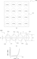
- Fig. 2 is an external view of the cushioning structure for a battery according to the first embodiment of the present invention, where (a) is a plan view of the cushioning structure for a battery, and (b) is a side view of the cushioning structure for a battery.
- Fig. 3 is a schematic cross-sectional view of the cushioning structure for a battery according to the first embodiment of the present invention, where Fig. 3(a) is a cross-sectional view taken along line AA in Fig.
- Fig. 4 is an explanatory diagram of the operation of the cushioning structure for a battery according to the first embodiment of the present invention, where (a) is a schematic cross-sectional view showing a state in which a compressive force is applied to the cushioning structure for a battery, and (b) is a graph showing the relationship between the compression ratio and the surface pressure.
- the battery 1 is composed of a cell stack in which a plurality of cells 20 are stacked, and the cell stack is supported by a housing (case wall) that houses the cell stack and a support member for supporting the cell stack.
- Fig. 1(a) shows a part of the housing (or support member) 30.
- a battery cushioning structure 10 is provided between adjacent cells 20 and between the cells 20 and the housing (or support member) 30.
- a battery cushioning structure 10 may be provided for each single cell 20, or a battery cushioning structure 10 may be provided for each of multiple cells 20. Also, multiple battery cushioning structures 10 can be stacked and used between adjacent cells 20 and between the cells 20 and the housing (or support member) 30.
- a cell stack 20X is housed inside a housing 30X.
- the housing 30X is supported by a pair of support members 30Y.
- a battery cushioning structure 10 is provided between the housing 30X and the support members 30Y.
- a battery cushioning structure can also be provided between adjacent cells in the cell stack 20X.
- the battery buffer structure 10 can suppress stress on the cell 20.
- the battery buffer structure 10 is configured to have a heat insulating function.
- the battery cushioning structure 10 includes a cushioning sheet 100, and interposing members 210, 220 disposed between the cushioning sheet 100 and the battery components (such as the cells 20 and the housing (or support member) 30).
- the interposing members 210, 220 are not limited to a configuration in which they directly contact the battery components, so long as they are disposed between the cushioning sheet 100 and the battery components.
- the buffer sheet 100 is made of an elastic body. It is preferable to use a material for this elastic body whose hardness, measured by JIS K 6253 durometer type E, is 50 to 90 degrees (more preferably 60 to 80 degrees). This allows the buffer function to be optimally exerted. More specifically, EPDM, silicone rubber, etc. can be used.
- a structure for fixing the buffer sheet 100 and the intermediate members 210, 220 is not necessary. However, if the positioning is not possible, a structure for fixing the buffer sheet 100 and the intermediate members 210, 220 must be provided. For example, a structure for bonding the buffer sheet 100 and the intermediate members 210, 220 with double-sided tape or a structure for positioning the buffer sheet 100 and the intermediate members 210, 220 by storing them in a bag-shaped film can be used, or other suitable known technology can be used.
- a structure for bonding the buffer sheet 100 and the battery components with double-sided tape can be used to position the buffer sheet 100 and the battery components.
- a structure for positioning the buffer sheet 100 and the intermediate members 210, 220 may be provided on the battery components.
- both the buffer sheet 100 and the intermediate members 210, 220 are made of a material having heat insulating properties.
- the other member can be made of a material that does not have heat insulating properties.
- a highly heat insulating elastic material such as flame retardant rubber or flame retardant elastomer can be suitably used as the material for the buffer sheet 100.
- the intermediate members 210, 220 When the intermediate members 210, 220 are to have a heat insulating function, they can be made of a thin non-flammable board mainly composed of non-asbestos natural mineral magnesium silicate. When the intermediate members 210, 220 are to have a heat insulating function, the intermediate members 210, 220 can be called heat insulating members.
- the interposing members 210, 220 are made of sheet-like (thin plate-like) materials so that the overall thickness of the battery cushioning structure 10 does not become too thick.
- the interposing members 210, 220 in this embodiment are made of sheet-like materials as shown in the figure.
- the buffer sheet 100 has a plurality of protrusions 120a, 120b. These protrusions 120a, 120b are configured to be hollow inside, and the space within the cavity is configured to be open (open) on the side opposite the protrusion direction of the protrusion. In other words, the buffer sheet 100 can be said to have a plurality of protrusions 120a, 120b that are hollow inside and open on the side opposite the protrusion direction.
- a plurality of protrusions 120a and 120b are provided on both sides of the buffer sheet 100.
- the outlines of the protrusions 120a and 120b are shown in dotted lines to make the arrangement of the protrusions 120a and 120b easier to understand.
- the protrusions 120a provided on one side of the buffer sheet 100 and the protrusions 120b provided on the other side of the buffer sheet 100 are arranged alternately vertically and horizontally.
- the height of the protrusions 120a and the height of the protrusions 120b are configured to be the same.
- the functions of both sides of the battery cushioning structure 10 are equivalent, so there is no need to check the front and back when installing the battery cushioning structure 10.
- the plan view shown in FIG. 2(a) is merely one example of the arrangement of the protrusions 120a and 120b, and it goes without saying that the number and arrangement of the protrusions 120a and 120b can be appropriately set according to the dimensions of the buffer sheet 100.
- the protrusions 120a and 120b are alternately arranged parallel or perpendicular to the four sides of the buffer sheet 100, but the protrusions 120a and 120b may be arranged diagonally alternately to the four sides.
- protrusion 120a protrudes toward interposing member 210 and can be said to be an internally hollow protrusion that is open on the side opposite the protruding direction. Also, protrusion 120a can be said to protrude toward the side opposite interposing member 220 and can be said to be an internally hollow protrusion that is open on the interposing member 220 side.
- protrusion 120b protrudes toward interposing member 220 and can be considered to be an internally hollow protrusion that is open on the side opposite the protruding direction. Also, protrusion 120b can be considered to be an internally hollow protrusion that protrudes toward the side opposite interposing member 210 and can be considered to be an internally hollow protrusion that is open on the interposing member 210 side.
- H1 is the maximum thickness of the buffer sheet 100 in the protruding direction of the protrusion when no external force is acting on the battery cushioning structure 10.
- FIG. 3(b) the dimensions of each part of the buffer sheet 100 when no external force is acting on it are shown.
- H is the maximum thickness of the buffer sheet 100 in the protruding direction of the protrusion
- T1 is the thickness of the flat part of the buffer sheet 100
- T2 is the thickness of the body part of the protrusions 120a and 120b
- T3 is the thickness of the tip part of the protrusions 120a and 120b
- L is the distance between the tip parts of the adjacent protrusions 120a and 120b
- d is the inclination angle of the body part of the protrusions 120a and 120b with respect to the flat part.
- T1 can be set to about 0.1 mm to 10 mm. In order to fully exert the cushioning function, it is preferable to satisfy H>3 ⁇ T (T1, T2, T3).
- the length and width of the buffer sheet 100 should be equal to or slightly smaller than the length and width of the cells 20.
- T2 can be set to about 0.1 mm to 10 mm.
- the density of the protrusions 120a, 120b can be about 1 to 6 pieces/ cm2 .
- the buffer structure 10 for a battery when the buffer structure 10 for a battery is compressed until the maximum thickness H1 of the buffer sheet 100 in the protruding direction of the protrusion when no external force is acting on the buffer structure 10 for a battery is halved, the back side of the most distal end of the protrusion 120a does not come into contact with the interposing member 220 and a space is maintained between the protrusion 120a and the interposing member 220. That is, as shown in FIG.
- EPDM with a hardness of Duro A 75, elongation of 250%, and tensile strength of 6.8 MPa was used as the material for the buffer sheet 100.
- the material characteristics of hardness are based on the JIS standard JIS K6253, and the measurement conditions are durometer type A, and the material characteristics of elongation and tensile strength are based on the JIS standard JIS K6251, and the measurement conditions are an elongation speed of 500 mm/min.
- the intermediate member 210 was a thin non-combustible board with a thickness of 1.2 mm and a thermal conductivity of 0.2 W/mK, mainly composed of non-asbestos natural mineral magnesium silicate.
- FIG. 4(b) is a graph showing the relationship between the compression ratio of the protrusions 120a, 120b in this specific example and the surface pressure between the protrusions 120a, 120b and the intermediate members 210, 220. The actual measurement conditions for this graph are a temperature of 25° C.
- the surface pressure does not increase in the parts without the protrusions, so the increase in the reaction force of the entire buffer sheet can be suppressed, but the surface pressure also increases suddenly in the parts where the protrusions come into contact.
- the interposing members 210, 220 are provided between the cushioning sheet 100 and the battery components (cells 20, housing 30, etc.). Therefore, the stress caused by the protruding parts 120a, 120b provided on the cushioning sheet 100 is dispersed by the interposing members 210, 220. In this way, the interposing members 210, 220 of this embodiment have a stress dispersion function that distributes the stress caused by the protruding parts 120a, 120b. Note that the interposing members 210, 220 have a stress dispersion function as long as they have a certain degree of rigidity.
- the interposing members 210, 220 have a heat insulating function, the transfer of heat can be suppressed even if the temperature of one of the cells 20 suddenly rises for some reason.
- the protrusions 120a, 120b in this embodiment are configured so that the area enclosed by the outline of a cross section perpendicular to the protrusion direction gradually narrows toward the tip in the protrusion direction.
- the outline of the protrusions 120a, 120b in this embodiment is a roughly truncated cone shape with the tip of the cone being a curved surface. Therefore, when the protrusions 120a, 120b are cut on a surface perpendicular to the protrusion direction, the outline is a circle, and the area of the circle is configured so that it gradually narrows toward the tip in the protrusion direction.
- This configuration makes it possible to increase the volume of the hollow portion of the protrusions 120a and 120b to suppress a sudden increase in the elastic repulsive force and to make it easier to maintain the space even when the buffer sheet 100 is compressed, while reducing the area of the tip of the protrusions 120a and 120b. Therefore, the contact area between the protrusions 120a and 120b and the cell 20, the housing 30, etc. is reduced, and heat transfer can be suppressed.
- the external shape of the protrusion is not limited to the generally truncated cone shape described in Example 1, and various shapes can be used.
- Example 2 a case where the external shape of the protrusion is a hemispherical shape will be described.
- Example 2 5 shows a second embodiment of the present invention.
- the configuration in which the outer shape of the protrusion is a hemispherical shape will be described. Since the other configurations and functions are the same as those in the first embodiment, the same components are given the same reference numerals and the description thereof will be omitted as appropriate.
- FIG. 5 is an explanatory diagram of a cushioning structure for a battery according to a second embodiment of the present invention, where (a) is a plan view of the cushioning structure for a battery, (b) is a side view of the cushioning sheet, and (c) is a graph showing the relationship between the compression ratio and the surface pressure.
- the cushioning structure for a battery 10X is composed of a cushioning sheet 100X and interposing members 210, 220.
- the interposing members 210, 220 are as described in Example 1. Note that in FIG. 5(a), only the interposing member 210 is shown.
- the necessity for a structure to fix the cushioning sheet 100X and the interposing members 210, 220, and the structure when they are fixed are also as described in Example 1.
- the configuration when the cushioning structure for a battery 10X is provided with a heat insulating function is also as described in Example 1.
- the buffer sheet 100X has a plurality of protrusions 121a and 121b. As in the first embodiment, these protrusions 121a and 121b are also configured to be hollow, and the space inside the cavity is configured to open (open) on the side opposite to the protruding direction of the protrusion. In other words, the buffer sheet 100 can be said to have a plurality of protrusions 121a and 121b that are hollow inside and open on the side opposite to the protruding direction.
- This embodiment differs from the first embodiment only in that the external shape of the protrusions 121a and 121b is hemispherical. In FIG.
- the outlines of the hollow portions in the leftmost protrusion 121a and the second protrusion 121b from the left are shown by dotted lines.
- a plurality of protrusions 121a and 121b are provided on both sides of the buffer sheet 100X.
- the outlines of the protrusions 121a and 121b are shown in dotted lines in a see-through manner.
- the protrusions 121a provided on one side of the buffer sheet 100X and the protrusions 121b provided on the other side of the buffer sheet 100X are arranged alternately vertically and horizontally.
- the height of the protrusions 121a and the height of the protrusions 121b are configured to be the same as in Example 1.
- the plan view shown in Fig. 5(a) is merely an example of the arrangement of the protrusions 121a and 121b, and it goes without saying that the number and arrangement of the protrusions 121a and 121b can be appropriately set according to the dimensions of the buffer sheet 100X, etc.
- the protrusions 121a and 121b are alternately arranged parallel or perpendicular to the four sides of the buffer sheet 100, but the protrusions 121a and 121b may be arranged diagonally alternately to the four sides.
- protrusion 121a protrudes toward interposing member 210 and can be said to be an internally hollow protrusion that is open on the side opposite the protruding direction. Also, protrusion 121a can be said to protrude toward the side opposite interposing member 220 and can be said to be an internally hollow protrusion that is open on the interposing member 220 side.
- protrusion 121b protrudes toward interposing member 220 and can be considered to be a hollow protrusion with an open side opposite the protruding direction. Also, protrusion 121b protrudes toward the opposite side from interposing member 210 and can be considered to be a hollow protrusion with an open side toward interposing member 210.
- FIG. 5(b) shows the dimensions of each part of the buffer sheet 100X when no external force is applied.
- H is the maximum thickness of the buffer sheet 100X in the protruding direction of the protrusions
- T1 is the thickness of the flat portion of the buffer sheet 100X
- L is the distance between the tip ends of the adjacent protrusions 121a and 121b.
- T1 can be set to about 0.1 mm to 10 mm.
- the length and width of the buffer sheet 100X (length and width when viewed in a plan view) should be equal to or slightly smaller than the length and width of the cell 20.
- the density of the protrusions 121a and 121b can be about 1 to 6 pieces/ cm2 .
- the cushioning structure for batteries 10X when the cushioning structure for batteries 10X is compressed to half the maximum thickness of the cushioning sheet 100X in the protruding direction of the protrusion with no external force acting on the cushioning structure for batteries 10X, the back side of the most distal end of the protrusion 121a does not come into contact with the interposing member 220, and a space is maintained between the protrusion 121a and the interposing member 220.
- EPDM with a hardness of Duro A 75, an elongation of 250%, and a tensile strength of 6.8 MPa was used as the material for the buffer sheet 100X.
- the measurement conditions for each material characteristic were the same as in Example 1.
- the intermediate member 210 was a thin non-combustible board with a thickness of 1.2 mm and a thermal conductivity of 0.2 W/mK, mainly composed of magnesium silicate, a non-asbestos natural mineral.
- Figure 5 (c) is a graph showing the relationship between the compression ratio of the protrusions 121a, 121b in this specific example and the surface pressure between the protrusions 121a, 121b and the intermediate members 210, 220.
- This graph was obtained by 3D nonlinear structural analysis, and the analysis conditions were set as follows: analysis element: hexahedral primary element, temperature: room temperature, buffer sheet material: EPDM, insulation material: non-flammable board.
- analysis element hexahedral primary element
- temperature room temperature
- buffer sheet material EPDM
- insulation material non-flammable board.
- the battery cushioning structure 10X according to this embodiment which is configured as described above, can also achieve the same effects as those of the first embodiment.
- the shape of the outer shape of the protrusion may be other than the approximately truncated cone shape described in Example 1 and the hemispherical shape described in Example 2. That is, the protrusion may be configured so that the area surrounded by the outer shape of the cross section perpendicular to the protrusion direction gradually narrows toward the tip in the protrusion direction.
- a protrusion 122 having a quadrangular pyramid tip with a curved surface may be used. Note that Fig. 6(a) is a plan view of the protrusion 122, and Fig. 6(b) is a side view.
- the shape is not limited to a quadrangular pyramid, and a shape having a multi-sided pyramid tip with a curved surface, such as a triangular pyramid or a pentagonal pyramid, may also be used.
- a protrusion 123 having a shape like a cylinder cut in half may also be used.
- Fig. 6(c) is a plan view of the protrusion 123
- Fig. 6(d) is a view of the protrusion 123 in the P1 direction in Fig. 6(c)
- Fig. 6(e) is a view of the protrusion 123 in the P2 direction.
- the inside of the protruding portions 122 and 123 is hollow.
- the present invention also includes a configuration in which protrusions are provided on only one side.
- a configuration in which an intervening member is placed only on the side on which the protrusions are provided can be adopted. This allows the intervening member to perform a stress dispersion function of dispersing stress caused by the protrusions.
- an intervening member is placed only on the side opposite the side on which the protrusions are provided. This makes it possible to prevent air from escaping from the hollow portion, so that even if the compression rate of the protrusions is 50%, it becomes easier to maintain a space behind the protrusions.
- the buffer sheet and the interposing member are separate members, but the buffer structure for the battery can also be configured with a member that has an integral part that corresponds to the buffer sheet and an integral part that corresponds to the interposing member.
- the buffer sheet and the interposing member can also be configured to be integrated.
Landscapes
- Chemical & Material Sciences (AREA)
- Chemical Kinetics & Catalysis (AREA)
- Electrochemistry (AREA)
- General Chemical & Material Sciences (AREA)
- Engineering & Computer Science (AREA)
- Manufacturing & Machinery (AREA)
- Battery Mounting, Suspending (AREA)
- Secondary Cells (AREA)
Priority Applications (4)
| Application Number | Priority Date | Filing Date | Title |
|---|---|---|---|
| KR1020257017619A KR20250099363A (ko) | 2023-02-16 | 2024-02-14 | 전지용 완충구조 |
| EP24756905.6A EP4668437A1 (en) | 2023-02-16 | 2024-02-14 | Battery cushioning structure |
| CN202480005477.0A CN120391013A (zh) | 2023-02-16 | 2024-02-14 | 电池用缓冲构造 |
| JP2025501172A JPWO2024172064A1 (https=) | 2023-02-16 | 2024-02-14 |
Applications Claiming Priority (2)
| Application Number | Priority Date | Filing Date | Title |
|---|---|---|---|
| JP2023022778 | 2023-02-16 | ||
| JP2023-022778 | 2023-02-16 |
Publications (1)
| Publication Number | Publication Date |
|---|---|
| WO2024172064A1 true WO2024172064A1 (ja) | 2024-08-22 |
Family
ID=92421889
Family Applications (1)
| Application Number | Title | Priority Date | Filing Date |
|---|---|---|---|
| PCT/JP2024/004981 Ceased WO2024172064A1 (ja) | 2023-02-16 | 2024-02-14 | 電池用緩衝構造 |
Country Status (5)
| Country | Link |
|---|---|
| EP (1) | EP4668437A1 (https=) |
| JP (1) | JPWO2024172064A1 (https=) |
| KR (1) | KR20250099363A (https=) |
| CN (1) | CN120391013A (https=) |
| WO (1) | WO2024172064A1 (https=) |
Citations (7)
| Publication number | Priority date | Publication date | Assignee | Title |
|---|---|---|---|---|
| JP2007165698A (ja) * | 2005-12-15 | 2007-06-28 | Mitsubishi Electric Corp | 電力貯蔵デバイス |
| JP2010165597A (ja) * | 2009-01-16 | 2010-07-29 | Toyota Motor Corp | 蓄電装置 |
| JP2010211963A (ja) * | 2009-03-06 | 2010-09-24 | Toyota Motor Corp | 蓄電装置 |
| EP3125332A1 (en) * | 2015-07-27 | 2017-02-01 | LG Chem, Ltd. | Battery module, battery pack comprising the battery module and vehicle comprising the battery pack |
| JP2020004556A (ja) | 2018-06-27 | 2020-01-09 | 住友理工株式会社 | 電池モジュール用緩衝シート |
| JP2021140968A (ja) * | 2020-03-06 | 2021-09-16 | ニチアス株式会社 | 電池用断熱材及び電池 |
| JP2022146852A (ja) * | 2021-03-22 | 2022-10-05 | 住友理工株式会社 | 電池モジュール用緩衝スペーサ |
-
2024
- 2024-02-14 JP JP2025501172A patent/JPWO2024172064A1/ja active Pending
- 2024-02-14 WO PCT/JP2024/004981 patent/WO2024172064A1/ja not_active Ceased
- 2024-02-14 KR KR1020257017619A patent/KR20250099363A/ko active Pending
- 2024-02-14 EP EP24756905.6A patent/EP4668437A1/en active Pending
- 2024-02-14 CN CN202480005477.0A patent/CN120391013A/zh active Pending
Patent Citations (7)
| Publication number | Priority date | Publication date | Assignee | Title |
|---|---|---|---|---|
| JP2007165698A (ja) * | 2005-12-15 | 2007-06-28 | Mitsubishi Electric Corp | 電力貯蔵デバイス |
| JP2010165597A (ja) * | 2009-01-16 | 2010-07-29 | Toyota Motor Corp | 蓄電装置 |
| JP2010211963A (ja) * | 2009-03-06 | 2010-09-24 | Toyota Motor Corp | 蓄電装置 |
| EP3125332A1 (en) * | 2015-07-27 | 2017-02-01 | LG Chem, Ltd. | Battery module, battery pack comprising the battery module and vehicle comprising the battery pack |
| JP2020004556A (ja) | 2018-06-27 | 2020-01-09 | 住友理工株式会社 | 電池モジュール用緩衝シート |
| JP2021140968A (ja) * | 2020-03-06 | 2021-09-16 | ニチアス株式会社 | 電池用断熱材及び電池 |
| JP2022146852A (ja) * | 2021-03-22 | 2022-10-05 | 住友理工株式会社 | 電池モジュール用緩衝スペーサ |
Also Published As
| Publication number | Publication date |
|---|---|
| KR20250099363A (ko) | 2025-07-01 |
| JPWO2024172064A1 (https=) | 2024-08-22 |
| CN120391013A (zh) | 2025-07-29 |
| EP4668437A1 (en) | 2025-12-24 |
Similar Documents
| Publication | Publication Date | Title |
|---|---|---|
| CN109075275B (zh) | 具有缓冲部件的电芯组 | |
| CN206541873U (zh) | 电池模组 | |
| JP4639583B2 (ja) | 燃料電池 | |
| US20080124625A1 (en) | Casing For a Sealed Battery | |
| KR102873734B1 (ko) | 에너지 저장 시스템 | |
| CN210136909U (zh) | 温控组件及电池包 | |
| US20240055699A1 (en) | Thermally Robust Cell Assembly, and Cell Module Comprising Such a Cell Assembly | |
| JP2021163538A (ja) | 断熱材およびバッテリー | |
| JP2017027673A (ja) | 電池モジュール | |
| WO2024172064A1 (ja) | 電池用緩衝構造 | |
| WO2016031628A1 (ja) | 電池パック | |
| JP2023135758A (ja) | バッテリー構造の断熱部材およびバッテリー構造 | |
| EP4462564A1 (en) | Panel assembly, battery cell block comprising same, battery module and battery pack | |
| CN113745725A (zh) | 电池模组 | |
| CN207765506U (zh) | 一种燃料电池抗三维冲击结构 | |
| US20250105428A1 (en) | Battery buffering member | |
| CN206370447U (zh) | 电池包 | |
| WO2020133674A1 (zh) | 电池模组以及电池包 | |
| JP2023152549A (ja) | バッテリー用緩衝材 | |
| CN209344144U (zh) | 一种电池模组及其端板组件 | |
| CN222190827U (zh) | 一种燃料电池的电堆及其缓冲结构 | |
| WO2021261166A1 (ja) | 燃料電池 | |
| JPWO2018011948A1 (ja) | 燃料電池スタック | |
| CN223871595U (zh) | 一种提高电芯堆叠安全的软芯电池包 | |
| CN121149522A (zh) | 隔热材料及配备有该隔热材料的电池模组 |
Legal Events
| Date | Code | Title | Description |
|---|---|---|---|
| 121 | Ep: the epo has been informed by wipo that ep was designated in this application |
Ref document number: 24756905 Country of ref document: EP Kind code of ref document: A1 |
|
| ENP | Entry into the national phase |
Ref document number: 20257017619 Country of ref document: KR Kind code of ref document: A |
|
| WWE | Wipo information: entry into national phase |
Ref document number: CN2024800054770 Country of ref document: CN Ref document number: 202480005477.0 Country of ref document: CN |
|
| ENP | Entry into the national phase |
Ref document number: 2025501172 Country of ref document: JP Kind code of ref document: A |
|
| WWE | Wipo information: entry into national phase |
Ref document number: 2025501172 Country of ref document: JP |
|
| WWP | Wipo information: published in national office |
Ref document number: 1020257017619 Country of ref document: KR |
|
| WWP | Wipo information: published in national office |
Ref document number: 202480005477.0 Country of ref document: CN |
|
| WWE | Wipo information: entry into national phase |
Ref document number: 2024756905 Country of ref document: EP |
|
| NENP | Non-entry into the national phase |
Ref country code: DE |
|
| ENP | Entry into the national phase |
Ref document number: 2024756905 Country of ref document: EP Effective date: 20250916 |
|
| WWP | Wipo information: published in national office |
Ref document number: 2024756905 Country of ref document: EP |