WO2024166931A1 - ホルムアルデヒド吸収システム、吸収方法、および吸収システムの設計方法 - Google Patents
ホルムアルデヒド吸収システム、吸収方法、および吸収システムの設計方法 Download PDFInfo
- Publication number
- WO2024166931A1 WO2024166931A1 PCT/JP2024/004059 JP2024004059W WO2024166931A1 WO 2024166931 A1 WO2024166931 A1 WO 2024166931A1 JP 2024004059 W JP2024004059 W JP 2024004059W WO 2024166931 A1 WO2024166931 A1 WO 2024166931A1
- Authority
- WO
- WIPO (PCT)
- Prior art keywords
- absorption
- liquid
- formaldehyde
- absorption tower
- section
- Prior art date
- Legal status (The legal status is an assumption and is not a legal conclusion. Google has not performed a legal analysis and makes no representation as to the accuracy of the status listed.)
- Ceased
Links
Images




Classifications
-
- C—CHEMISTRY; METALLURGY
- C07—ORGANIC CHEMISTRY
- C07C—ACYCLIC OR CARBOCYCLIC COMPOUNDS
- C07C45/00—Preparation of compounds having >C = O groups bound only to carbon or hydrogen atoms; Preparation of chelates of such compounds
- C07C45/78—Separation; Purification; Stabilisation; Use of additives
- C07C45/783—Separation; Purification; Stabilisation; Use of additives by gas-liquid treatment, e.g. by gas-liquid absorption
-
- B—PERFORMING OPERATIONS; TRANSPORTING
- B01—PHYSICAL OR CHEMICAL PROCESSES OR APPARATUS IN GENERAL
- B01D—SEPARATION
- B01D53/00—Separation of gases or vapours; Recovering vapours of volatile solvents from gases; Chemical or biological purification of waste gases, e.g. engine exhaust gases, smoke, fumes, flue gases, aerosols
- B01D53/14—Separation of gases or vapours; Recovering vapours of volatile solvents from gases; Chemical or biological purification of waste gases, e.g. engine exhaust gases, smoke, fumes, flue gases, aerosols by absorption
-
- C—CHEMISTRY; METALLURGY
- C07—ORGANIC CHEMISTRY
- C07C—ACYCLIC OR CARBOCYCLIC COMPOUNDS
- C07C45/00—Preparation of compounds having >C = O groups bound only to carbon or hydrogen atoms; Preparation of chelates of such compounds
- C07C45/78—Separation; Purification; Stabilisation; Use of additives
-
- C—CHEMISTRY; METALLURGY
- C07—ORGANIC CHEMISTRY
- C07C—ACYCLIC OR CARBOCYCLIC COMPOUNDS
- C07C47/00—Compounds having —CHO groups
- C07C47/02—Saturated compounds having —CHO groups bound to acyclic carbon atoms or to hydrogen
- C07C47/04—Formaldehyde
Definitions
- the present invention relates to a system for absorbing formaldehyde, an absorption method, and a method for designing an absorption system.
- a manufacturing apparatus uses multiple absorption towers to react reactive gas with water to produce an aqueous formaldehyde solution.
- the process of reacting reactive gas with water is divided into a first absorption stage and a second absorption stage, with one absorption tower being used in the first absorption stage and 2 to 6 absorption towers being used in the second absorption stage.
- the total length of the towers in the first absorption stage is, for example, 2 to 8 m
- the total length of the towers in the second absorption stage is, for example, 4 to 6 m (Patent Document 1).
- the present invention was made in consideration of the above problems, and aims to provide a formaldehyde absorption system, an absorption method, and a method for designing an absorption system that can be constructed at low cost while still providing sufficient performance.
- the formaldehyde absorption system according to the first invention of the present application is an absorption system that absorbs a formaldehyde gas composition produced by the silver method with a liquid and recovers it as an aqueous formaldehyde solution, the formaldehyde gas composition containing at least 15.7% by weight to 27.0% by weight of formaldehyde, 17.3% by weight to 29.5% by weight of water, and 43.7% by weight to 65.0% by weight of an inert gas, the absorption system comprising one absorption tower or two absorption towers connected in series, the absorption tower comprising a cylindrical body with a lid and a bottom, and a formaldehyde gas recovery tank.
- the absorption tower has an absorption section that absorbs the sulphur composition with a liquid and a cooling section that cools the liquid in the absorption section, the internal diameter of the absorption tower is 1,000 mm or more and 3,000 mm or less, the total length of all the body parts included in the absorption system, excluding the lid and bottom, is 20,000 mm or more and 40,000 mm or less, the absorption system includes a total of two or more cooling sections, the liquid residence time per meter of length is 0.8 minutes or more in the absorption section provided at the most downstream of the absorption tower in the liquid flow, and the cumulative residence time of the liquid in all the absorption sections included in the absorption system is 150 minutes or more.
- the liquid residence time per meter of length is 1 minute or more and 2 minutes or less.
- the cumulative liquid residence time in all the absorption sections included in the absorption system is 150 minutes or more and 2,000 minutes or less.
- the absorption tower may further include a liquid supply section that supplies liquid from above in the direction of gravity.
- the liquid residence time per meter of length is 0.8 minutes or more and 3 minutes or less.
- the cumulative liquid residence time in all the absorption sections included in the absorption system is 150 minutes or more and 1,000 minutes or less.
- the absorption tower comprises an absorption tower provided on the upstream side and an absorption tower provided on the downstream side in the liquid flow, and the liquid discharged from the bottom of the absorption tower provided on the upstream side may flow into the absorption tower provided on the downstream side from the top of the absorption tower provided on the downstream side.
- the absorption tower may further include a gas supply unit that supplies the formaldehyde gas composition from the lower part in the direction of gravity.
- the absorption tower may have multiple absorption sections.
- the formaldehyde absorption method according to the second invention of the present application is an absorption method in which a formaldehyde gas composition produced by the silver method is absorbed with a liquid and recovered as an aqueous formaldehyde solution, the formaldehyde gas composition containing at least 15.7% by weight to 27.0% by weight of formaldehyde, 17.3% by weight to 29.5% by weight of water, and 43.7% by weight to 65.0% by weight of an inert gas, the absorption system comprising one absorption tower or two absorption towers connected in series, the absorption tower comprising a cylindrical body with a lid and a bottom, and a liquid absorber for absorbing the formaldehyde gas composition.
- the system includes an absorption section that absorbs liquid by the body and a cooling section that cools the liquid in the absorption section, the internal diameter of the absorption tower is 1,000 mm or more and 3,000 mm or less, the total length of the body section included in the absorption system is 20,000 mm or more and 40,000 mm or less, the absorption system includes a total of two or more cooling sections, the liquid residence time per meter of length is 0.8 minutes or more in the absorption section provided at the most downstream side of the absorption tower in the liquid flow, and a step of flowing water into the absorption tower so that the cumulative residence time of the liquid in all absorption sections included in the absorption system is 150 minutes or more.
- the liquid residence time per meter of length is 0.8 minutes or more and 3 minutes or less.
- the cumulative liquid residence time in all the absorption sections included in the absorption system is 150 minutes or more and 2,000 minutes or less.
- the design method according to the third invention of the present application is a design method for an absorption system that absorbs a formaldehyde gas composition produced by the silver method with a liquid and recovers it as an aqueous formaldehyde solution, the absorption system comprising two absorption towers connected in series, the absorption towers comprising a cylindrical body with a lid and a bottom, an absorption section that absorbs the formaldehyde gas composition with a liquid, and a cooling section that cools the liquid in the absorption section, the formaldehyde gas composition comprising 15.7% by weight or more and 27.0% by weight or less of formaldehyde and 17.3% by weight or more and 29.5% by weight or less of formaldehyde.
- This design method specifies that the internal diameter of the absorption tower is 1,000 mm or more and 3,000 mm or less, the total length of the body included in the absorption system is 20,000 mm or more and 40,000 mm or less, the absorption system includes a total of two or more cooling sections, the liquid residence time per meter of length in the absorption section provided at the most downstream side of the absorption tower in the liquid flow is 0.8 minutes or more, and the cumulative residence time of the liquid in all absorption sections included in the absorption system is 150 minutes or more.
- the two absorption towers include one existing absorption tower and one newly installed absorption tower, and the newly installed absorption tower may be connected in series to the existing absorption tower.
- the liquid residence time per meter of length is 0.8 minutes or more and 3 minutes or less.
- the cumulative liquid residence time in all the absorption sections included in the absorption system is 150 minutes or more and 2,000 minutes or less.
- the present invention provides a formaldehyde absorption system, an absorption method, and a method for designing an absorption system that can be constructed at low cost while still providing sufficient performance.
- FIG. 1 is a schematic diagram of a first formaldehyde absorption system according to a first embodiment of the present invention.
- FIG. 2 is a schematic diagram of a second formaldehyde absorption system according to a second embodiment of the present invention.
- 1 is a table showing an embodiment of the present invention.
- 13 is a table showing comparative examples.
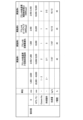
- 1 is a table showing five conditions used in a numerical simulation and the simulation results obtained under those conditions.
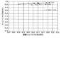
- 1 is a graph showing the relationship between liquid residence time per unit height and Liquid H 2 O/Feed F.
- 1 is a graph showing the relationship between cumulative residence time and cumulative formaldehyde conversion rate.
- 1 is a graph showing the relationship between cumulative formaldehyde conversion rate and formaldehyde recovery rate.
- the first formaldehyde absorption system 10 is an absorption system that absorbs a formaldehyde gas composition produced by the silver method into a liquid and recovers it as an aqueous formaldehyde solution, and mainly comprises a first absorption tower 100, a liquid supply unit 20, and a gas supply unit 30. In this embodiment, pure water is used as the liquid.
- the first absorption tower 100 mainly comprises a lidded, bottomed, cylindrical body 110, five absorption sections 130a-130e that absorb the formaldehyde gas composition into the liquid, and three cooling sections 150a-150c that cool the liquid in the absorption sections.
- the body 110 is a straight cylinder whose top and bottom openings are airtightly covered with a spherical crown-shaped lid and bottom, and is preferably made of stainless steel.
- the length of the body 110 excluding the lid and bottom is the axial length of the straight cylinder, in other words the length of the straight portion of the straight cylinder, and is 20,000 mm to 40,000 mm.
- the internal diameter of the first absorption tower 100 i.e., the internal diameter of the straight cylindrical portion of the body 110, is 1,000 mm to 3,000 mm.
- a pipe 170 is connected to the top spherical crown of the body 110, and gas in the first absorption tower 100 flows out.
- Absorption units 130a to 130e are stored in body 110 in order from the top vertically.
- Absorption units 130a and 130d are so-called tray-type units, and each has a configuration in which trays with multiple holes are stacked in the direction of gravity, and liquid is injected from above and gas is injected from below, dissolving the gas in the liquid. More specifically, liquid is stored on the top surface of the tray, and gas that has passed through the multiple holes from below the tray passes through the liquid on the tray. At this time, the gas dissolves in the liquid.
- Absorption sections 130b and 130e are of the so-called filling type, and each has a configuration in which a large number of metal rings are randomly filled, into which liquid is injected from above the force of gravity and gas is injected from below the force of gravity, causing the gas to dissolve in the liquid. More specifically, liquid is sprayed onto the filled metal rings from above the force of gravity, and the liquid drips down between the metal rings. Gas rising from below the force of gravity comes into contact with these droplets, and the gas dissolves into the liquid.
- the part filled with a large number of metal rings is called the filling section.
- the absorption section 130c is of the fillable type described above. Liquid flowing in from above due to gravity passes through a large number of metal rings and dissolves the gas.
- Absorption sections 130b, 130c, and 130e are each provided with a cooling section 150a, 150b, and 150c that cools the liquid in absorption sections 130b, 130c, and 130e.
- Each of cooling sections 150a, 150b, and 150c mainly includes a heat exchanger 151a, 151b, and 151c, and a pump 152a, 152b, and 152c.
- Pump 152a is connected to a pipe provided near the bottom of absorption section 130b, and sends the liquid flowing out from absorption section 130b to heat exchanger 151a.
- Heat exchanger 151a cools the liquid from pump 152a and sends it out by gravity upward of absorption section 130b. The sent out fluid passes through absorption section 130b again.
- a pipe 153 is connected to the pipe between the heat exchanger 151a and the absorbing section 130b, and the diluted formaldehyde aqueous solution is injected into the absorbing section 130b through the pipe 153.
- the diluted formaldehyde aqueous solution it is possible to improve the amount of formaldehyde recovered in all steps of producing formaldehyde, including the step related to the first formaldehyde absorption system 10 and the steps before and after it.
- the liquid flowing out from the bottom of the absorbing section 130b is cooled through the pump 152a, the heat exchanger 151a, and the pipe, and is returned to the upward direction of the absorbing section 130b by gravity.
- the pump 152b also sends liquid from near the bottom of the absorption section 130c to the heat exchanger 151b, and the heat exchanger 151b also cools the liquid from the pump 152b and sends it upwards due to gravity to the absorption section 130c. In this way, the liquid flowing out from the bottom of the absorption section 130c is cooled through the pump 152b, the heat exchanger 151b, and the piping, and is returned upwards due to gravity to the absorption section 130c.
- the pump 152c also sends liquid from near the bottom of the absorption section 130e to the heat exchanger 151c, and the heat exchanger 151c also cools the liquid from the pump 152c and sends it above the absorption section 130e due to gravity. In this way, the liquid flowing out from the bottom of the absorption section 130e is cooled through the pump 152c, the heat exchanger 151c, and the piping, and is returned to the absorption section 130e above the gravity.
- a piping 160 is provided between the pump 152c and the heat exchanger 151c to allow the liquid in which the formaldehyde is dissolved to flow out. A portion of the liquid flowing out of the pump 152c flows out of the system 10 from the piping 160, and the remainder flows into the heat exchanger 151c.
- the liquid supply unit 20 mainly comprises a flow controller 21, a transmitter 22, a flowmeter 23, a control valve 24, and a pipe 25, and supplies liquid, for example pure water, to the first absorption tower 100 from near its top.
- the transmitter 22 transmits the value output by the flowmeter 23 to the flow controller 21.
- One end of the pipe 25 is connected to a storage tank (not shown), and the other end is connected to near the top of the first absorption tower 100 via a flow meter 23 and an adjustment valve 24. Pure water is placed in the storage tank, and is supplied to near the top of the first absorption tower 100 via the pipe 25.
- the area near the top is between the top cap and the top end of the absorption section 130a. That is, the liquid supply section 20 is connected to the first absorption tower 100 from the storage tank via the flow meter 23 and adjustment valve 24.
- the flow controller 21 is connected to a flowmeter 23 and an adjustment valve 24, and opens and closes the adjustment valve 24 according to the value of the flowmeter 23 while taking into account the flow rate of the liquid flowing through the pipe 25a, thereby controlling the amount of liquid flowing into the first absorption tower 100. Since a constant amount of liquid always flows through the pipe 25a, the amount of liquid flowing into the first absorption tower 100 is controlled by adjusting the flow rate of the liquid flowing through the pipe 25a.
- the feed flow rate of the raw material gas and the pure water is determined from the formaldehyde concentration and production amount required in the final product. Since the feed flow rate of the raw material gas and the pure water is determined by the liquid residence time, the liquid residence time is determined so that the feed flow rate of the raw material gas and the pure water is the determined amount, and the inner diameter and the longitudinal length of the absorption tower are determined so that the determined liquid residence time is obtained. In other words, since the feed flow rate of the raw material gas and the pure water is limited by the inner diameter and the longitudinal length of the absorption tower, it is necessary to determine the inner diameter and the longitudinal length of the first absorption tower 100 from the formaldehyde concentration and production amount required in the final product.
- the size of the first absorption tower 100 is determined so that the liquid residence time per meter of length in the absorption section 130e provided at the most downstream of the first absorption tower 100 is a predetermined period.
- the length referred to here is the length including the interval between multiple trays in the tray type, and the length packed with metal rings in the packed type.
- the liquid residence time in each of the absorption sections 130a to 130e is the residence time of the liquid in that absorption section, and is calculated by the following formula. Note that the circulating flow rate in the following formula is the flow rate per unit time of the liquid circulating through each absorption section.
- (Residence time of liquid in each absorption section) (amount of liquid retained in each absorption section) / (flow rate of liquid exiting, excluding circulation flow rate)
- the liquid residence time per meter of length is 0.8 minutes or more and 3 minutes or less, and it is even better if it is 1 minute or more and 2 minutes or less.
- the first absorption tower 100 is designed with respect to the internal diameter and longitudinal length thereof such that the cumulative residence time of the liquid in all of the absorption sections 130a-130e included in the absorption system 10 is a predetermined period.
- the cumulative residence time is the sum of the residence times of the liquid in all of the absorption sections 130a-130e in the first absorption tower 100.
- the predetermined period is preferably 150 minutes or more and 2,000 minutes or less, more preferably 150 minutes or more and 1500 minutes or less, and even more preferably 150 minutes or more and 1,000 minutes or less.
- the cumulative residence time that satisfies these periods and times is determined in advance by computational simulation or experiment, and the internal diameter and longitudinal length of the first absorption tower 100 are determined according to the cumulative residence time that has been determined in advance.
- Formaldehyde exists as substances such as methylene glycol and hemiformal due to various reactions in the liquid of the absorption sections 130a to 130e.
- the ratio of formaldehyde that is converted to other substances relative to the amount of formaldehyde flowing into each absorption section 130a to 130e is called the formaldehyde conversion rate.
- the sum of the formaldehyde conversion rates in all absorption sections 130a to 130e in the first absorption tower 100 is called the cumulative formaldehyde conversion rate.
- the ratio of the amount of formaldehyde absorbed by the liquid in the first absorption tower 100 and recovered as a product to the total amount of formaldehyde supplied to the first absorption tower 100 is called the formaldehyde recovery rate.
- the gas supply unit 30 is, for example, a formaldehyde reactor using a silver catalyst, and supplies a formaldehyde gas composition to the first absorption tower 100 from near its bottom. More specifically, the gas supply unit 30 generates a formaldehyde gas composition from a raw material gas containing a circulating gas such as methanol gas, water vapor, air, and an inert gas, and supplies the aldehyde gas composition as a gas from near the bottom of the first absorption tower 100.
- the formaldehyde gas composition contains at least 15.7% by weight to 27.0% by weight of formaldehyde, 17.3% by weight to 29.5% by weight of water, and 43.7% by weight to 65.0% by weight of an inert gas.
- the inert gas is, for example, nitrogen, but may also contain other inert gases.
- the liquid supply unit 20 directly injects pure water from the pipe 25 into the first absorption tower 100.
- the flow controller 21 controls the adjustment valve 24 so that the flow meter 23 indicates a predetermined inflow rate, and an appropriate amount of liquid is injected into the first absorption tower 100.
- the liquid supply unit 20 can also adjust the inflow rate as appropriate depending on the actual operating conditions.
- the inflow rate is the value mentioned above.
- the pure water falls under the force of gravity from the top of the first absorption tower 100, reaches the absorption section 130a, and then passes through the absorption sections 130b, 130c, 130d, and 130e in order, before flowing from the bottom of the first absorption tower 100 into the pipe 160.
- the gas supply unit 30 supplies the formaldehyde gas composition as a gas from near the bottom of the first absorption tower 100.
- the formaldehyde gas composition rises upward due to gravity from the bottom of the first absorption tower 100, passes through absorption units 130e, 130d, 130c, and 130b in order, reaches absorption unit 130a, and then flows out from the top of the first absorption tower 100 into the pipe 170.
- the pure water containing the formaldehyde gas composition that has passed through the absorption section 130a reaches the next absorption section 130b.
- the formaldehyde gas composition rising from below due to gravity comes into contact with the pure water sprayed onto the metal ring from above due to gravity, and the formaldehyde gas composition dissolves in the pure water.
- more formaldehyde gas composition dissolves in the pure water than when it passed through the absorption section 130a.
- the formaldehyde gas can be liquefied by contacting the pure water containing the formaldehyde gas composition that has been cooled by the cooling section 150a with the formaldehyde gas.
- the pure water containing the formaldehyde gas composition that has passed through absorption section 130b reaches the next absorption section 130c.
- absorption section 130c the formaldehyde gas composition rising from below comes into contact with the pure water that has been poured onto the metal ring and tray from above due to gravity, and the formaldehyde gas composition dissolves in the pure water.
- more of the formaldehyde gas composition dissolves in the pure water than when it passed through absorption section 130b.
- the formaldehyde gas can be liquefied by contacting the pure water containing the formaldehyde gas composition that has been cooled by the cooling section 150b with the formaldehyde gas.
- the pure water drips from above under the force of gravity onto multiple trays and is stored there, and the formaldehyde gas composition passes through holes in the trays from below under the force of gravity, during which the formaldehyde gas composition dissolves in the pure water.
- the pure water containing the formaldehyde gas composition that has passed through absorption section 130d reaches the next absorption section 130e.
- the formaldehyde gas composition rising from below due to gravity comes into contact with the pure water sprayed onto the metal ring from above due to gravity, and the formaldehyde gas composition dissolves in the pure water.
- more formaldehyde gas composition dissolves in the pure water than when it passed through absorption section 130d.
- the pure water containing the formaldehyde gas composition that flows out of the absorption section 130e flows into the cooling section 150c and is cooled, after which a portion of it is returned to the upward direction of the absorption section 130e by gravity, and the remainder flows out of the system 10 through the pipe 160.
- the liquid that flows out is a 45% by weight aqueous formaldehyde solution.
- the first formaldehyde absorption system 10 absorbs the formaldehyde gas composition with the liquid and recovers it as an aqueous formaldehyde solution.
- a formaldehyde absorption system, an absorption method, and a method for designing an absorption system are obtained that can be constructed at low cost while still providing sufficient performance.
- FIG. 2 a second formaldehyde absorption system 40, an absorption method, and a method for designing an absorption system according to a second embodiment of the present invention will be described.
- the same components as those in the first embodiment will be given the same reference numerals and will not be described.
- the second formaldehyde absorption system 40 is an absorption system that absorbs the formaldehyde gas composition produced by the silver method into a liquid and recovers it as an aqueous formaldehyde solution, and mainly comprises two absorption towers, a second absorption tower 400 and a third absorption tower 600, a liquid supply unit 20, and a gas supply unit 30.
- pure water is used as the liquid.
- the second absorption tower 400 mainly comprises a lidded, bottomed, cylindrical body 410, two absorption sections 430d, 430e that absorb the formaldehyde gas composition with liquid, and one cooling section 450 that cools the liquid in the absorption section 430e.
- the body 410 is a straight cylinder with a top opening and a bottom opening airtightly covered with a spherical cap, and is preferably made of stainless steel.
- the length of the body 410 excluding the cover and bottom is the axial length of the straight cylinder.
- the internal diameter of the second absorption tower 400 i.e., the internal diameter of the straight cylindrical part of the body 410, is 1,000 mm or more and 3,000 mm or less.
- a pipe 470 is connected to the top spherical cap of the body 410, and gas containing the formaldehyde gas composition in the second absorption tower 400 flows out.
- the pipe 470 is connected to the bottom of the third absorption tower 600 and supplies gas containing a formaldehyde gas composition to the third absorption tower 600 from the bottom in the direction of gravity.
- the absorbing sections 430d and 430e are stored in the body section 410 in order from the top vertically.
- the absorbing section 430d has a similar configuration to the absorbing section 130a according to the first embodiment.
- the absorbing section 430e has a configuration substantially similar to the absorbing section 130e according to the first embodiment. Detailed description of the absorbing sections 430d and 430e is omitted.
- the absorbing section 430e is provided with a cooling section 450 for cooling the liquid in the absorbing section 430e.
- the cooling section 450 mainly includes a pump 452.
- the pump 452 is connected to a pipe provided near the bottom of the second absorption tower 400, and sends the liquid flowing out of the absorbing section 430e to the heat exchanger 451a.
- the liquid flowing out from the bottom of the absorbing section 430e is cooled through the pump 452, the heat exchanger 451a, and the pipe, and is returned to the upper part of the absorbing section 430e under gravity.
- a pipe 460 is provided between the pump 452 and the upper part of the absorbing section 430e to allow the liquid in which formaldehyde is dissolved to flow out.
- the heat exchanger 451a may not be provided, and the liquid may not be cooled.
- the third absorption tower 600 mainly comprises a lidded, bottomed, cylindrical body 610, three absorption sections 630a, 630b, and 630c that absorb the formaldehyde gas composition with liquid, and two cooling sections 650a and 650b that cool the liquid in the absorption sections 630b and 630c, respectively.
- the body 610 is a straight cylinder with its top and bottom openings airtightly covered with a spherical cap, and is preferably made of stainless steel.
- the length of the body 610 excluding the lid and bottom is the axial length of the straight cylinder.
- the internal diameter of the third absorption tower 600 i.e., the internal diameter of the straight cylinder part of the body 610, is 1,000 mm or more and 3,000 mm or less.
- a pipe 170 is connected to the top spherical cap of the body 610, and gas in the third absorption tower 600 flows out.
- the sum of the length of the body 610 excluding the lid and bottom and the length of the body 410 excluding the lid and bottom, i.e., the sum of the axial length of the straight cylinder of the body 610 and the axial length of the straight cylinder of the body 410, more specifically, the total length of the parts excluding the lids and bottoms of all the bodies 410, 610 included in the absorption system 40 is 20,000 mm or more and 40,000 mm or less.
- Absorption sections 630a, 630b, and 630c are stored in the body section 610 in order from the top vertically.
- Absorption section 630a is substantially similar to absorption section 130a according to the first embodiment
- absorption section 630b is substantially similar to absorption section 130b according to the first embodiment
- absorption section 630c is substantially similar to absorption section 130c according to the first embodiment.
- Each of the absorption sections 630b, 630c is provided with a cooling section 650a, 650b that cools the liquid in the absorption section.
- the cooling section 650a mainly includes a heat exchanger 651a and a pump 652a.
- the pump 652a is connected to a pipe connected to the bottom of the absorption section 630b, and sends the liquid flowing out from the absorption section 630b to the heat exchanger 651a.
- the heat exchanger 651a cools the liquid from the pump 652a and sends it upward by gravity to the absorption section 630b.
- a pipe 653 is connected to the pipe between the heat exchanger 651a and the absorption section 630b, and a diluted formaldehyde aqueous solution is injected into the absorption section 630b through the pipe 653.
- the cooling section 650b mainly includes a heat exchanger 651b and a pump 652b.
- the pump 652b is connected to a pipe connected to the bottom of the absorption section 630c, more specifically, to the spherical crown that forms the bottom of the third absorption tower 600, and sends the liquid that flows in from the absorption section 630c to the heat exchanger 651b.
- the heat exchanger 651b cools the liquid from the pump 652b and sends it above the absorption section 630c due to gravity. In other words, the liquid that flows out from the bottom of the absorption section 630c is cooled through the pump 652b, the heat exchanger 651b, and the pipe, and is returned above the absorption section 630c due to gravity.
- a pipe 660 is provided to discharge the liquid in which formaldehyde is dissolved.
- a portion of the liquid discharged from the pump 652b is supplied to the second absorption tower 400 by gravity from the pipe 660, and the remainder flows into the heat exchanger 651b. That is, the liquid discharged from the lower part, more specifically the bottom part, of the third absorption tower 600, which is installed upstream in the liquid flow, flows into the second absorption tower 400 from the upper part, more specifically near the top, of the second absorption tower 400, which is installed downstream. This state means that the second absorption tower 400 and the third absorption tower 600 are connected in series.
- the liquid supply unit 20 supplies liquid to the third absorption tower 600 from above in the direction of gravity.
- the configuration of the liquid supply unit 20 is substantially the same as that of the first embodiment.
- the gas supply unit 30 supplies the formaldehyde gas composition as a gas from the lower part of the second absorption tower 400 in the direction of gravity, in other words, from near the bottom of the second absorption tower 400.
- the formaldehyde gas composition is the same as in the first embodiment.
- the flow controller 21 of the liquid supply unit 20 controls the flow meter 22 and the control valve 24 according to a predetermined inflow rate to inject an appropriate amount of liquid into the third absorption tower 600.
- the liquid supply unit 20 can also adjust the inflow rate as appropriate according to the actual operating conditions.
- the inflow rate is the value mentioned above.
- the pure water falls under the force of gravity from the top of the third absorption tower 600, reaches the absorption section 630a, passes through the absorption sections 630b and 630c, and flows from the bottom of the third absorption tower 600 to the cooling section 650b.
- the pure water passes through piping 660 connected to cooling section 650b and flows into the second absorption tower 400 from near the top of the second absorption tower 400.
- the pure water then falls under the force of gravity from near the top of the second absorption tower 400, passes through absorption sections 430d and 430e, and flows from the bottom of the second absorption tower 400 to the cooling section 450, and then flows out of the second formaldehyde absorption system 40 through piping 460.
- the gas supply unit 30 supplies the formaldehyde gas composition as a gas from near the bottom of the second absorption tower 400.
- the formaldehyde gas composition rises upward due to gravity from near the bottom of the second absorption tower 400, passes through absorption units 430e and 430d, and flows out from the top of the second absorption tower 400 into pipe 470.
- the formaldehyde gas composition that flows out into pipe 470 is supplied to near the bottom of the third absorption tower 600.
- the formaldehyde gas composition rises upward due to gravity from near the bottom, passes through absorption units 630c, 630b, and 630a, and flows out from the top of the third absorption tower 600 into pipe 170.
- the process by which the formaldehyde gas composition dissolves in the pure water in the absorption units 630a, 630b, 630c, 430d, and 430e is similar to that of the absorption units 130a, 130b, 130c, 130d, and 130e in the first embodiment, so a description thereof will be omitted.
- the pure water containing the formaldehyde gas composition that flows out of the absorption section 630c flows into the cooling section 650b and is cooled, after which a portion of it is returned to the upward direction of the absorption section 630c under gravity, and the remainder is supplied from the pipe 660 to the second absorption tower 400.
- the pure water containing the formaldehyde gas composition that is supplied to the second absorption tower 400 flows through the absorption sections 430d and 430e, a portion of it flows into the cooling section 450 and is cooled, and then returned to the upward direction of the absorption section 430e under gravity, and the remainder flows out from the pipe 460 to the outside of the second formaldehyde absorption system.
- the liquid that flows out is a formaldehyde aqueous solution having a concentration of 37% by weight or more and 55% by weight or less.
- the first formaldehyde absorption system 10 absorbs the formaldehyde gas composition with the liquid and recovers it as a formaldehyde aqueous solution.
- the third absorption tower 600 is assumed to be an existing absorption tower equipped with two cooling sections 650a, 650b, has an internal diameter of 2,450 mm, and has a body 610 with a length of 18,000 mm excluding the lid and bottom, to which the second absorption tower 400 is newly installed.
- the specifications for the second absorption tower 400 are as follows: the internal diameter is 1,000 mm or more and 3,000 mm or less, and the length of the body 410 is determined so that the total length of all the bodies 410, 610 included in the absorption system 40, excluding the lid and bottom, is 20,000 mm or more and 40,000 mm or less.
- the length of the body 610 of the existing absorption tower, excluding the lid and bottom is 18,000 mm
- the length of the body 410 of the second absorption tower, excluding the lid and bottom is set to 8,200 mm
- the internal diameter is set to 1,800 mm.
- the inflow rate is determined so that the liquid residence time per meter of length in the absorption section 430e is 0.8 minutes or more, and the cumulative liquid residence time in all absorption sections 630a, 630b, 630c, 430d, and 430e included in the second formaldehyde absorption system 40 is 150 minutes or more and 2,000 minutes or less.
- the inflow rate is determined in advance by calculation simulation and experiment so as to achieve these times.
- the third absorption tower 600 already has two cooling sections 650a and 650b, it is not necessary to provide a new cooling section, but a new cooling section 450 may be provided as in this embodiment.
- the total length of all the torsos 410, 610 included in the absorption system 40, excluding the lid and bottom, only needs to be 20,000 mm or more and 40,000 mm or less, so the size of the newly installed second absorption tower 400 can be reduced, thereby improving the performance of the absorption system at low cost.
- a formaldehyde absorption system, an absorption method, and a method for designing an absorption system are obtained that can be constructed at low cost while still providing sufficient performance.
- the longitudinal length of the absorption sections (T-1) 130a and 630a was 5,700 mm
- the longitudinal length of the absorption sections (P-1) 130b and 630b was 1,500 mm
- the longitudinal length of the absorption sections (P-2) 130c and 630c was 3,000 mm
- the longitudinal length of the absorption sections (T-2) 130d and 430d was 1,200 mm
- the longitudinal length of the absorption sections (P-3) 130e and 430e was 3,000 mm.
- Case 2 a formaldehyde gas composition having a blending ratio of 25.4 wt % formaldehyde, 23.0 wt % water vapor, and 51.6 wt % inert gas was applied to the first absorption tower 100.
- the first absorption tower 100 had the same configuration as in Case 1, but the inflow amount of the formaldehyde gas composition was 125% of that in Case 1.
- Case 3 a formaldehyde gas composition having a blending ratio of 23.8 wt % formaldehyde, 25.9 wt % water vapor, and 50.3 wt % inert gas was applied to the first absorption tower 100.
- the first absorption tower 100 had the same configuration as in Case 1, but the inflow amount of the formaldehyde gas composition was 120% of that in Case 1.
- Case 4 a formaldehyde gas composition having a blend ratio of 25.0 wt % formaldehyde, 25.0 wt % water vapor, and 50.0 wt % inert gas was applied to the first absorption tower 100.
- the first absorption tower 100 has the same configuration as in Case 1.
- Case 5 a formaldehyde gas composition having a blending ratio of 21.8 wt % formaldehyde, 16.2 wt % water vapor, and 62.0 wt % inert gas was applied to the first absorption tower 100.
- the first absorption tower 100 has the same configuration as in Case 1.
- Case 7 In Case 7, the proportion of water vapor was reduced to near the explosive range compared to Case 3, and a formaldehyde gas composition having a blending ratio of 26.6 wt % formaldehyde, 17.3 wt % water vapor, and 56.2 wt % inert gas was applied to the first absorption tower 100.
- the first absorption tower 100 has the same configuration as Case 1.
- the condition of water vapor being less than 17.3 wt % was not feasible because it was dangerous in the explosive range in the process of generating a formaldehyde gas composition by a reaction in the preceding stage.
- the recycled gas is also used for temperature adjustment in the gas supply unit 30, and if the recycled gas is not used, it becomes difficult to adjust the temperature in the formaldehyde production reaction in the gas supply unit 30. It was confirmed that a formaldehyde gas composition could be obtained even when the formaldehyde concentration was as high as 27.0% by weight and the inert gas concentration was as low as 43.7% by weight.
- the longitudinal length of the absorption section (T-1) 130a, 630a is 5,700 mm
- the longitudinal length of the absorption section (P-1) 130b, 630b is 1,500 mm
- the longitudinal length of the absorption section (P-2) 130c, 630c is 3,000 mm
- the longitudinal length of the absorption section (T-2) 130d, 430d is 1,200 mm
- the longitudinal length of the absorption section (P-3) 130e, 430e is 3,000 mm.
- a small second absorption tower 400 is added to the existing third absorption tower 600.
- the internal diameter of the existing third absorption tower 600 i.e., the internal diameter of the straight cylindrical part of the body 610, is 2,450 mm, and the total length of the body 610 excluding the lid and the bottom is 18,000 mm.
- the internal diameter of the added second absorption tower 400 i.e., the internal diameter of the straight cylindrical part of the body 410, is 1,800 mm, and the total length of the body 410 excluding the lid and the bottom is 8,200 mm.
- the second absorption tower 400 includes one cooling section 450
- the third absorption tower 600 includes two cooling sections 650a, 650b.
- the number of absorption towers is two, and the number of cooling sections is three.
- a formaldehyde gas composition containing 25.4% by weight of formaldehyde, 23.0% by weight of water, and 51.6% by weight of inert gas was supplied to the second formaldehyde absorption system 40.
- 7,167 kg of an aqueous formaldehyde solution with a formaldehyde concentration of 45% was obtained per hour.
- Example 2 The specifications of the existing first absorption tower 100 were changed.
- the internal diameter of the existing first absorption tower 100 i.e., the internal diameter of the right cylindrical portion of the body 110, was set to 1,500 mm, and the total length of the body 110 excluding the lid and the bottom was set to 24,200 mm.
- the first absorption tower 100 has three cooling sections 150a to 150c. That is, the number of cooling towers is one, and the number of cooling sections is three.
- a formaldehyde gas composition having the same composition and the same amount per hour as in Example 1 was supplied to the first formaldehyde absorption system 10. As a result, 7,167 kg of a formaldehyde aqueous solution having a formaldehyde concentration of 45% by weight was obtained per hour.
- Example 3 The amount of the formaldehyde gas composition supplied to the existing first absorption tower 100 was 400% of that in Example 2.
- the internal diameter of the existing first absorption tower 100 i.e., the internal diameter of the right cylindrical portion of the body 110, was 2,450 mm, and the total length of the body 110 excluding the lid and bottom was 24,200 mm. That is, the number of cooling towers was one, and the number of cooling parts was three.
- a formaldehyde gas composition having the same composition as that in Example 1 and four times the amount supplied per hour was supplied to the first formaldehyde absorption system 10. As a result, 19,112 kg of a formaldehyde aqueous solution having a formaldehyde concentration of 45% by weight was obtained per hour.
- Example 4 An absorption tower having the same configuration was added to the existing third absorption tower 600.
- the internal diameter of the existing third absorption tower 600 i.e., the internal diameter of the right cylindrical part of the body 610, was 2,450 mm, and the total length of the body 610 excluding the lid and the bottom was 18,000 mm. That is, the number of cooling towers was two, and the number of cooling parts was four.
- a formaldehyde gas composition having the same composition as that in Example 1 and four times the hourly supply amount was supplied to the second formaldehyde absorption system 40. As a result, 19,112 kg of a formaldehyde aqueous solution having a formaldehyde concentration of 45 wt % was obtained per hour.
- Comparative Example 4 The specifications of Comparative Example 2 were changed.
- the inner diameter of the absorption tower i.e., the inner diameter of the straight cylindrical part of the body, was not changed to 2,450 mm, and the total length of the body excluding the lid and bottom was changed to 45,000 mm.
- the absorption tower has four cooling sections.
- the supply amount of the formaldehyde gas composition was 400% of that of Example 2.
- the supply amount of the formaldehyde gas composition was 400% of the absorption tower of Comparative Example 2.
- 19,112 kg of formaldehyde aqueous solution with a formaldehyde concentration of 45 wt% was obtained per hour.
- the absorption tower was too long, so the manufacturing cost of the absorption tower and the cost of the factory building were high, which is not practical from a commercial perspective.
- Comparative Example 2 it is possible to set the number of cooling sections to 16, providing a cooling section for each tray in the tray type and for each filling section in the filling type, but this is not commercially realistic because the number of cooling sections would increase and costs would rise.
- the applicant performed a numerical simulation for the first formaldehyde absorption system 10 under the following five conditions.
- the longitudinal length of the absorption section (T-1) 130a is 5,700 mm
- the longitudinal length of the absorption section (P-1) 130b is 1,500 mm
- the longitudinal length of the absorption section (P-2) 130c is 3,000 mm
- the longitudinal length of the absorption section (T-2) 130d is 1,200 mm
- the longitudinal length of the absorption section (P-3) 130e is 3,000 mm.
- a formaldehyde gas composition containing 25.4% by weight of formaldehyde, 23.0% by weight of H 2 O , and 51.6% by weight of N 2 and others was supplied to the first formaldehyde absorption system 10 at a flow rate of 35,680 kg/h.
- the flow rate of formaldehyde (Gas F) is 9072.6 kg/h
- the flow rate of H 2 O (Gas H 2 O) is 8208.5 kg/h.
- the flow rate of formaldehyde in the diluted formaldehyde aqueous solution supplied from the pipe 153 (DF) is 420.2 kg/h
- the flow rate of H 2 O (DH 2 O) is 1897.2 kg/h.
- the flow rate of H 2 O supplied from the liquid supply unit 20 (PH 2 O) is 1446.0 kg/h.
- Liquid H 2 O/Feed F (wt %) was 35.2 wt %, which was calculated by the following formula.
- (Liquid H 2 O / Feed F (wt%)) (Flow rate of H 2 O supplied from outside to the absorption tower) / (Flow rate of formaldehyde supplied from outside to the absorption tower)
- the flow rate of H 2 O supplied from the outside to the absorption tower is the sum of (D H 2 O) and (P H 2 O)
- the flow rate of formaldehyde supplied from the outside to the absorption tower is the sum of (Gas F) and (D F).
- a formaldehyde gas composition containing 25.4% by weight of formaldehyde, 23.0% by weight of H 2 O , and 51.6% by weight of N 2 and others was supplied to the first formaldehyde absorption system 10 at a flow rate of 26,760 kg/h.
- the flow rate of formaldehyde (Gas F) is 6804.4 kg/h
- the flow rate of H 2 O (Gas H 2 O) is 6156.4 kg/h.
- the flow rate of formaldehyde in the diluted formaldehyde aqueous solution supplied from the pipe 153 (DF) is 315.1 kg/h
- the flow rate of H 2 O (DH 2 O) is 1422.5 kg/h.
- the flow rate of H 2 O supplied from the liquid supply unit 20 is 700.0 kg/h.
- the ratio of Liquid H 2 O/Feed F (wt %) was 29.8 wt %.
- 47.4% by weight of formaldehyde was obtained.
- the liquid residence time per unit height in the absorption section (P-1) 130b was 5.2 min/m
- the liquid residence time per unit height in the absorption section (P-2) 130c was 6.2 min/m
- the liquid residence time per unit height in the absorption section (T-2) 130d was 1.4 min/m
- the liquid residence time per unit height in the absorption section (P-3) 130e was 1.3 min/m.
- a formaldehyde gas composition containing 26.2% by weight of formaldehyde, 20.6% by weight of H 2 O , and 53.2% by weight of N 2 and others was supplied to the first formaldehyde absorption system 10 at a flow rate of 25,956 kg/h.
- the flow rate of formaldehyde (Gas F) is 6804.5 kg/h
- the flow rate of H 2 O (Gas H 2 O) is 5352.1 kg/h.
- the flow rate of formaldehyde in the diluted formaldehyde aqueous solution supplied from the pipe 153 (DF) is 315.1 kg/h
- the flow rate of H 2 O (DH 2 O) is 1422.5 kg/h.
- the flow rate of H 2 O supplied from the liquid supply unit 20 is 700.0 kg/h.
- the ratio of Liquid H 2 O/Feed F was 29.8 wt %.
- 50.0% by weight of formaldehyde was obtained.
- the liquid residence time per unit height in the absorption section (P-1) 130b was 5.0 min/m
- the liquid residence time per unit height in the absorption section (P-2) 130c was 6.1 min/m
- the liquid residence time per unit height in the absorption section (T-2) 130d was 1.5 min/m
- the liquid residence time per unit height in the absorption section (P-3) 130e was 1.3 min/m.
- a formaldehyde gas composition containing 25.4% by weight of formaldehyde, 23.0% by weight of H 2 O , and 51.6% by weight of N 2 and others was supplied to the first formaldehyde absorption system 10 at a flow rate of 13,380 kg/h.
- the flow rate of formaldehyde (Gas F) is 3402.2 kg/h
- the flow rate of H 2 O (Gas H 2 O) is 3078.2 kg/h.
- the flow rate of formaldehyde in the diluted formaldehyde aqueous solution supplied from the pipe 153 (DF) is 157.6 kg/h
- the flow rate of H 2 O (DH 2 O) is 711.7 kg/h.
- the flow rate of H 2 O supplied from the liquid supply unit 20 is 245.0 kg/h.
- the ratio of Liquid H 2 O/Feed F (wt %) was 26.9 wt %.
- 48.0% by weight of formaldehyde was obtained.
- the liquid residence time per unit height in the absorption section (P-1) 130b was 7.3 min/m
- the liquid residence time per unit height in the absorption section (P-2) 130c was 8.9 min/m
- the liquid residence time per unit height in the absorption section (T-2) 130d was 3.5 min/m
- the liquid residence time per unit height in the absorption section (P-3) 130e was 1.5 min/m.
- a formaldehyde gas composition containing 26.2% by weight of formaldehyde, 20.6% by weight of H 2 O , and 53.2% by weight of N 2 and others was supplied to the first formaldehyde absorption system 10 at a flow rate of 12,978 kg/h.
- the flow rate of formaldehyde (Gas F) is 3402.3 kg/h
- the flow rate of H 2 O (Gas H 2 O) is 2676.0 kg/h.
- the flow rate of formaldehyde in the diluted formaldehyde aqueous solution supplied from the pipe 153 (DF) is 157.6 kg/h
- the flow rate of H 2 O (DH 2 O) is 711.7 kg/h.
- the flow rate of H 2 O supplied from the liquid supply unit 20 is 245.0 kg/h.
- the ratio of Liquid H 2 O/Feed F (wt %) was 26.9 wt %.
- 50.7% by weight of formaldehyde was obtained.
- the liquid residence time per unit height in the absorption section (P-1) 130b was 7.3 min/m
- the liquid residence time per unit height in the absorption section (P-2) 130c was 9.2 min/m
- the liquid residence time per unit height in the absorption section (T-2) 130d was 3.8 min/m
- the liquid residence time per unit height in the absorption section (P-3) 130e was 1.6 min/m.
- FIG. 6 shows a graph of the relationship between the liquid residence time per unit height and Liquid H 2 O / Feed F.
- the liquid residence time per unit height of the absorption section (P-3) 130e at the bottom of the tower is the shortest, at 0.8 to 1 min/m.
- the absorption section located at the bottom of the absorption tower has the largest gas flow rate and liquid flow rate compared to other absorption sections, and therefore has the largest amount of formaldehyde treatment, that is, the amount of formaldehyde dissolved in pure water.
- the specifications of the absorption section located at the bottom of the tower in this case, a specification that satisfies the liquid residence time per unit height of 0.8 min/m, were determined according to the required treatment amount for the system 10. Then, the inner diameter of the tower was calculated based on this specification, and a value of 1,000 mm to 3,000 mm was obtained. On the other hand, if the liquid retention time per unit height exceeds 3 min/m, it is necessary to increase the inner diameter of the absorption tower and the total length of all the body parts excluding the lid and the bottom, which makes the formaldehyde absorption system an excessively large facility, and the amortization period of the equipment cost is extended, resulting in poor economic efficiency. Therefore, the liquid retention time per unit height is preferably 3 min/m or less.
- Figure 7 is a graph showing the relationship between cumulative residence time and cumulative formaldehyde conversion rate obtained by simulation based on conditions 1 to 5. In all simulation results, it was found that when the cumulative residence time reached 150 minutes, the cumulative formaldehyde conversion rate reached 99%. In other words, it was found that a cumulative residence time of 150 minutes is necessary to achieve a cumulative formaldehyde conversion rate of 99% or more.
- Figure 8 is a graph showing the relationship between the cumulative formaldehyde conversion rate and the formaldehyde recovery rate obtained by a simulation based on conditions 1 to 5.
- the practical formaldehyde recovery rate is set to 99.5% or more.
- the cumulative residence time at this time is 150 minutes. From the above, it can be seen that a cumulative residence time of 150 minutes or more is necessary to achieve a formaldehyde recovery rate of about 99.5% or more.
- the manufacturing and operating costs of the absorption system can be reduced.
- the total length of all the body parts included in the absorption system only needs to be 20,000 mm or more and 40,000 mm or less, so the size of the entire absorption system can be reduced, thereby improving the performance of the absorption system at low cost.
- the cost of the factory building in which the absorption system is installed can be reduced.
- the body of the first to third absorption towers 100, 400, and 600 has been described as being a right cylinder, but it may also be a square tube, an oblique cylinder, or a curved or bent shape.
- cooling section it is not necessary to provide a cooling section for each absorption section, but two or more cooling sections may be provided in the first formaldehyde absorption system 10 and the second formaldehyde absorption system 40.
- the diluted formaldehyde aqueous solution is injected into the absorption section through the piping between the heat exchanger and the absorption section, but pure water may be injected instead of the diluted formaldehyde aqueous solution.
- the formaldehyde gas composition is produced by the silver method (silver catalyst method, excess methanol method) using silver as a catalyst.
- First absorption system 20 Liquid supply section 21 Flow controller 23 Flow meter 24 Control valve 25 Pipe 25a Pipe 30 Gas supply section 40
- Absorption system 100
- First absorption tower 110 Body section 130a Absorption section (T-1) 130b Absorbing part (P-1) 130c Absorbing section (P-2) 130d Absorption section (T-2) 130e Absorbing section (P-3) 150a cooling section 150b cooling section 150c cooling section 151a heat exchanger 151b heat exchanger 151c heat exchanger 152a pump 152b pump 152c pump 153 piping 160 piping 170 piping 400 second absorption tower 410 body section 430d absorption section (T-2) 430e Absorbing section (P-3) 450 Cooling section 452
- Third absorption tower 610 Body section 630a Absorption section (T-1) 630b Absorbing part (P-1) 630c Absorbing section (P-2) 650a Cooling section 650b Cooling section 651a Heat exchange
Landscapes
- Chemical & Material Sciences (AREA)
- Organic Chemistry (AREA)
- Engineering & Computer Science (AREA)
- Analytical Chemistry (AREA)
- General Chemical & Material Sciences (AREA)
- Oil, Petroleum & Natural Gas (AREA)
- Chemical Kinetics & Catalysis (AREA)
- Gas Separation By Absorption (AREA)
Priority Applications (2)
| Application Number | Priority Date | Filing Date | Title |
|---|---|---|---|
| KR1020257019861A KR20250143303A (ko) | 2023-02-08 | 2024-02-07 | 폼알데하이드 흡수 시스템, 흡수 방법, 및 흡수 시스템의 설계 방법 |
| JP2024576875A JPWO2024166931A1 (https=) | 2023-02-08 | 2024-02-07 |
Applications Claiming Priority (2)
| Application Number | Priority Date | Filing Date | Title |
|---|---|---|---|
| JP2023-017377 | 2023-02-08 | ||
| JP2023017377 | 2023-02-08 |
Publications (1)
| Publication Number | Publication Date |
|---|---|
| WO2024166931A1 true WO2024166931A1 (ja) | 2024-08-15 |
Family
ID=92262740
Family Applications (1)
| Application Number | Title | Priority Date | Filing Date |
|---|---|---|---|
| PCT/JP2024/004059 Ceased WO2024166931A1 (ja) | 2023-02-08 | 2024-02-07 | ホルムアルデヒド吸収システム、吸収方法、および吸収システムの設計方法 |
Country Status (3)
| Country | Link |
|---|---|
| JP (1) | JPWO2024166931A1 (https=) |
| KR (1) | KR20250143303A (https=) |
| WO (1) | WO2024166931A1 (https=) |
Citations (7)
| Publication number | Priority date | Publication date | Assignee | Title |
|---|---|---|---|---|
| JPS60215644A (ja) * | 1984-04-12 | 1985-10-29 | Mitsubishi Gas Chem Co Inc | ホルムアルデヒド水溶液の製造法 |
| JP2004083542A (ja) * | 2002-08-23 | 2004-03-18 | Nittetu Chemical Engineering Ltd | メタン発酵ガスの精製方法 |
| JP2012091130A (ja) * | 2010-10-28 | 2012-05-17 | Hitachi Ltd | Co2回収装置、co2回収方法及びco2捕捉材 |
| CN204803247U (zh) * | 2015-06-26 | 2015-11-25 | 天津福林超然科技发展有限公司 | 一种甲醇直接汽化的甲醛制备装置 |
| WO2016079544A1 (en) * | 2014-11-20 | 2016-05-26 | Johnson Matthey Public Limited Company | Process and apparatus for preparing an aqueous solution of formaldehyde |
| CN107056593A (zh) * | 2017-02-17 | 2017-08-18 | 唐山中浩化工有限公司 | 一种超大规模甲醛的生产方法及系统 |
| CN115160118A (zh) * | 2022-08-06 | 2022-10-11 | 枣庄市美辰化工有限公司 | 一种封闭式甲醛生产工艺流程 |
Family Cites Families (1)
| Publication number | Priority date | Publication date | Assignee | Title |
|---|---|---|---|---|
| DE2444586C3 (de) | 1974-09-18 | 1986-07-10 | Basf Ag, 6700 Ludwigshafen | Verfahren zur Herstellung von konzentrierten, wäßrigen Lösungen von Formaldehyd |
-
2024
- 2024-02-07 JP JP2024576875A patent/JPWO2024166931A1/ja active Pending
- 2024-02-07 KR KR1020257019861A patent/KR20250143303A/ko active Pending
- 2024-02-07 WO PCT/JP2024/004059 patent/WO2024166931A1/ja not_active Ceased
Patent Citations (7)
| Publication number | Priority date | Publication date | Assignee | Title |
|---|---|---|---|---|
| JPS60215644A (ja) * | 1984-04-12 | 1985-10-29 | Mitsubishi Gas Chem Co Inc | ホルムアルデヒド水溶液の製造法 |
| JP2004083542A (ja) * | 2002-08-23 | 2004-03-18 | Nittetu Chemical Engineering Ltd | メタン発酵ガスの精製方法 |
| JP2012091130A (ja) * | 2010-10-28 | 2012-05-17 | Hitachi Ltd | Co2回収装置、co2回収方法及びco2捕捉材 |
| WO2016079544A1 (en) * | 2014-11-20 | 2016-05-26 | Johnson Matthey Public Limited Company | Process and apparatus for preparing an aqueous solution of formaldehyde |
| CN204803247U (zh) * | 2015-06-26 | 2015-11-25 | 天津福林超然科技发展有限公司 | 一种甲醇直接汽化的甲醛制备装置 |
| CN107056593A (zh) * | 2017-02-17 | 2017-08-18 | 唐山中浩化工有限公司 | 一种超大规模甲醛的生产方法及系统 |
| CN115160118A (zh) * | 2022-08-06 | 2022-10-11 | 枣庄市美辰化工有限公司 | 一种封闭式甲醛生产工艺流程 |
Also Published As
| Publication number | Publication date |
|---|---|
| JPWO2024166931A1 (https=) | 2024-08-15 |
| KR20250143303A (ko) | 2025-10-01 |
Similar Documents
| Publication | Publication Date | Title |
|---|---|---|
| CN101333288B (zh) | 聚合物多元醇的汽提方法 | |
| AU2015249027B2 (en) | Carbon dioxide capturing system and method of operating same | |
| NO323638B1 (no) | Skrubber for behandling av avgass | |
| KR20130084979A (ko) | 폐가스로부터 이산화탄소 및 이산화황를 촉매적으로 제거하는 방법 | |
| CN103214009A (zh) | 一种合成氨脱碳工艺 | |
| WO2024166931A1 (ja) | ホルムアルデヒド吸収システム、吸収方法、および吸収システムの設計方法 | |
| CN112206740A (zh) | 一种分区控制的尿素水解反应器 | |
| CN116434855A (zh) | 碱基络合铁湿法脱除高炉煤气中硫化氢的系统及优化方法 | |
| CN115335323B (zh) | 用于生产硝酸的包含具有锯齿状堰的进料箱和整装填料的吸收塔和方法 | |
| KR101907609B1 (ko) | 암모니아수 회수 장치 및 암모니아수 회수 방법 | |
| KR100893692B1 (ko) | 냉각자켓을 구비한 흡수탑 | |
| CN104829438A (zh) | 一种甲醛生产方法及装置 | |
| KR100369247B1 (ko) | 피동 작동 2단 유량전환 방법 및 장치 | |
| EP4529965A1 (en) | Sieve tray for absorber | |
| RU2830188C1 (ru) | Абсорбционная колонна и способ производства азотной кислоты | |
| CN208660794U (zh) | 一种二硫化碳生产过程中加氢含硫尾气处理装置 | |
| US20250276283A1 (en) | Heat-integrated transformative carbon dioxide capture process | |
| Grozev et al. | Unsteady-state SO2 oxidation: practical results | |
| CN204544148U (zh) | 一种用于环己酮氨肟化反应的液氨蒸发装置 | |
| CN205235734U (zh) | 提高丙烯腈回收率并降低成本的急冷塔装置 | |
| US3134644A (en) | Production of super phosphoric acid | |
| US20170203275A1 (en) | Hydrogen-oxygen separation energy-generating system | |
| CN212757921U (zh) | 烟气有机胺法脱除二氧化硫的变流态湍泡式预吸收管 | |
| RU192222U1 (ru) | Устройство для подачи катализатора в реактор установки для получения элементарной серы | |
| EA005786B1 (ru) | Способ контактирования расплавленной мочевины с потоком газа |
Legal Events
| Date | Code | Title | Description |
|---|---|---|---|
| 121 | Ep: the epo has been informed by wipo that ep was designated in this application |
Ref document number: 24753374 Country of ref document: EP Kind code of ref document: A1 |
|
| WWE | Wipo information: entry into national phase |
Ref document number: 2024576875 Country of ref document: JP |
|
| WWE | Wipo information: entry into national phase |
Ref document number: 2501005114 Country of ref document: TH |
|
| NENP | Non-entry into the national phase |
Ref country code: DE |
|
| WWP | Wipo information: published in national office |
Ref document number: 1020257019861 Country of ref document: KR |
|
| 122 | Ep: pct application non-entry in european phase |
Ref document number: 24753374 Country of ref document: EP Kind code of ref document: A1 |