WO2024166509A1 - 熱交換装置及び全熱交換換気システム - Google Patents
熱交換装置及び全熱交換換気システム Download PDFInfo
- Publication number
- WO2024166509A1 WO2024166509A1 PCT/JP2023/043064 JP2023043064W WO2024166509A1 WO 2024166509 A1 WO2024166509 A1 WO 2024166509A1 JP 2023043064 W JP2023043064 W JP 2023043064W WO 2024166509 A1 WO2024166509 A1 WO 2024166509A1
- Authority
- WO
- WIPO (PCT)
- Prior art keywords
- straightening
- heat exchange
- airflow
- exchange device
- plate
- Prior art date
- Legal status (The legal status is an assumption and is not a legal conclusion. Google has not performed a legal analysis and makes no representation as to the accuracy of the status listed.)
- Ceased
Links
Images


Classifications
-
- F—MECHANICAL ENGINEERING; LIGHTING; HEATING; WEAPONS; BLASTING
- F24—HEATING; RANGES; VENTILATING
- F24F—AIR-CONDITIONING; AIR-HUMIDIFICATION; VENTILATION; USE OF AIR CURRENTS FOR SCREENING
- F24F5/00—Air-conditioning systems or apparatus not covered by F24F1/00 or F24F3/00, e.g. using solar heat or combined with household units such as an oven or water heater
- F24F5/0007—Air-conditioning systems or apparatus not covered by F24F1/00 or F24F3/00, e.g. using solar heat or combined with household units such as an oven or water heater cooling apparatus specially adapted for use in air-conditioning
- F24F5/0017—Air-conditioning systems or apparatus not covered by F24F1/00 or F24F3/00, e.g. using solar heat or combined with household units such as an oven or water heater cooling apparatus specially adapted for use in air-conditioning using cold storage bodies, e.g. ice
- F24F5/0021—Air-conditioning systems or apparatus not covered by F24F1/00 or F24F3/00, e.g. using solar heat or combined with household units such as an oven or water heater cooling apparatus specially adapted for use in air-conditioning using cold storage bodies, e.g. ice using phase change material [PCM] for storage
-
- F—MECHANICAL ENGINEERING; LIGHTING; HEATING; WEAPONS; BLASTING
- F24—HEATING; RANGES; VENTILATING
- F24F—AIR-CONDITIONING; AIR-HUMIDIFICATION; VENTILATION; USE OF AIR CURRENTS FOR SCREENING
- F24F12/00—Use of energy recovery systems in air conditioning, ventilation or screening
-
- F—MECHANICAL ENGINEERING; LIGHTING; HEATING; WEAPONS; BLASTING
- F24—HEATING; RANGES; VENTILATING
- F24F—AIR-CONDITIONING; AIR-HUMIDIFICATION; VENTILATION; USE OF AIR CURRENTS FOR SCREENING
- F24F13/00—Details common to, or for air-conditioning, air-humidification, ventilation or use of air currents for screening
- F24F13/08—Air-flow control members, e.g. louvres, grilles, flaps or guide plates
- F24F13/10—Air-flow control members, e.g. louvres, grilles, flaps or guide plates movable, e.g. dampers
- F24F13/14—Air-flow control members, e.g. louvres, grilles, flaps or guide plates movable, e.g. dampers built up of tilting members, e.g. louvre
- F24F13/15—Air-flow control members, e.g. louvres, grilles, flaps or guide plates movable, e.g. dampers built up of tilting members, e.g. louvre with parallel simultaneously tiltable lamellae
-
- F—MECHANICAL ENGINEERING; LIGHTING; HEATING; WEAPONS; BLASTING
- F24—HEATING; RANGES; VENTILATING
- F24F—AIR-CONDITIONING; AIR-HUMIDIFICATION; VENTILATION; USE OF AIR CURRENTS FOR SCREENING
- F24F3/00—Air-conditioning systems in which conditioned primary air is supplied from one or more central stations to distributing units in the rooms or spaces where it may receive secondary treatment; Apparatus specially designed for such systems
- F24F3/12—Air-conditioning systems in which conditioned primary air is supplied from one or more central stations to distributing units in the rooms or spaces where it may receive secondary treatment; Apparatus specially designed for such systems characterised by the treatment of the air otherwise than by heating and cooling
- F24F3/14—Air-conditioning systems in which conditioned primary air is supplied from one or more central stations to distributing units in the rooms or spaces where it may receive secondary treatment; Apparatus specially designed for such systems characterised by the treatment of the air otherwise than by heating and cooling by humidification; by dehumidification
- F24F3/1411—Air-conditioning systems in which conditioned primary air is supplied from one or more central stations to distributing units in the rooms or spaces where it may receive secondary treatment; Apparatus specially designed for such systems characterised by the treatment of the air otherwise than by heating and cooling by humidification; by dehumidification by absorbing or adsorbing water, e.g. using an hygroscopic desiccant
- F24F3/1429—Air-conditioning systems in which conditioned primary air is supplied from one or more central stations to distributing units in the rooms or spaces where it may receive secondary treatment; Apparatus specially designed for such systems characterised by the treatment of the air otherwise than by heating and cooling by humidification; by dehumidification by absorbing or adsorbing water, e.g. using an hygroscopic desiccant alternatively operating a heat exchanger in an absorbing/adsorbing mode and a heat exchanger in a regeneration mode
-
- F—MECHANICAL ENGINEERING; LIGHTING; HEATING; WEAPONS; BLASTING
- F24—HEATING; RANGES; VENTILATING
- F24F—AIR-CONDITIONING; AIR-HUMIDIFICATION; VENTILATION; USE OF AIR CURRENTS FOR SCREENING
- F24F7/00—Ventilation
-
- F—MECHANICAL ENGINEERING; LIGHTING; HEATING; WEAPONS; BLASTING
- F24—HEATING; RANGES; VENTILATING
- F24F—AIR-CONDITIONING; AIR-HUMIDIFICATION; VENTILATION; USE OF AIR CURRENTS FOR SCREENING
- F24F7/00—Ventilation
- F24F7/007—Ventilation with forced flow
- F24F7/013—Ventilation with forced flow using wall or window fans, displacing air through the wall or window
-
- F—MECHANICAL ENGINEERING; LIGHTING; HEATING; WEAPONS; BLASTING
- F28—HEAT EXCHANGE IN GENERAL
- F28D—HEAT-EXCHANGE APPARATUS, NOT PROVIDED FOR IN ANOTHER SUBCLASS, IN WHICH THE HEAT-EXCHANGE MEDIA DO NOT COME INTO DIRECT CONTACT
- F28D17/00—Regenerative heat-exchange apparatus in which a stationary intermediate heat-transfer medium or body is contacted successively by each heat-exchange medium, e.g. using granular particles
- F28D17/02—Regenerative heat-exchange apparatus in which a stationary intermediate heat-transfer medium or body is contacted successively by each heat-exchange medium, e.g. using granular particles using rigid bodies, e.g. of porous material
-
- F—MECHANICAL ENGINEERING; LIGHTING; HEATING; WEAPONS; BLASTING
- F28—HEAT EXCHANGE IN GENERAL
- F28D—HEAT-EXCHANGE APPARATUS, NOT PROVIDED FOR IN ANOTHER SUBCLASS, IN WHICH THE HEAT-EXCHANGE MEDIA DO NOT COME INTO DIRECT CONTACT
- F28D20/00—Heat storage plants or apparatus in general; Regenerative heat-exchange apparatus not covered by groups F28D17/00 or F28D19/00
- F28D20/02—Heat storage plants or apparatus in general; Regenerative heat-exchange apparatus not covered by groups F28D17/00 or F28D19/00 using latent heat
-
- F—MECHANICAL ENGINEERING; LIGHTING; HEATING; WEAPONS; BLASTING
- F28—HEAT EXCHANGE IN GENERAL
- F28F—DETAILS OF HEAT-EXCHANGE AND HEAT-TRANSFER APPARATUS, OF GENERAL APPLICATION
- F28F9/00—Casings; Header boxes; Auxiliary supports for elements; Auxiliary members within casings
- F28F9/02—Header boxes; End plates
- F28F9/026—Header boxes; End plates with static flow control means, e.g. with means for uniformly distributing heat exchange media into conduits
- F28F9/0265—Header boxes; End plates with static flow control means, e.g. with means for uniformly distributing heat exchange media into conduits by using guiding means or impingement means inside the header box
- F28F9/0268—Header boxes; End plates with static flow control means, e.g. with means for uniformly distributing heat exchange media into conduits by using guiding means or impingement means inside the header box in the form of multiple deflectors for channeling the heat exchange medium
-
- F—MECHANICAL ENGINEERING; LIGHTING; HEATING; WEAPONS; BLASTING
- F24—HEATING; RANGES; VENTILATING
- F24F—AIR-CONDITIONING; AIR-HUMIDIFICATION; VENTILATION; USE OF AIR CURRENTS FOR SCREENING
- F24F7/00—Ventilation
- F24F2007/005—Cyclic ventilation, e.g. alternating air supply volume or reversing flow direction
-
- Y—GENERAL TAGGING OF NEW TECHNOLOGICAL DEVELOPMENTS; GENERAL TAGGING OF CROSS-SECTIONAL TECHNOLOGIES SPANNING OVER SEVERAL SECTIONS OF THE IPC; TECHNICAL SUBJECTS COVERED BY FORMER USPC CROSS-REFERENCE ART COLLECTIONS [XRACs] AND DIGESTS
- Y02—TECHNOLOGIES OR APPLICATIONS FOR MITIGATION OR ADAPTATION AGAINST CLIMATE CHANGE
- Y02E—REDUCTION OF GREENHOUSE GAS [GHG] EMISSIONS, RELATED TO ENERGY GENERATION, TRANSMISSION OR DISTRIBUTION
- Y02E60/00—Enabling technologies; Technologies with a potential or indirect contribution to GHG emissions mitigation
- Y02E60/14—Thermal energy storage
Definitions
- a heat storage element that can store heat up to a predetermined temperature while absorbing heat and moisture from gas, and a ventilation unit using the same, are known (see, for example, Patent Document 1).
- each of the two ventilation units can supply and exhaust air.
- the rotation direction of the ventilation fan when supplying air and the rotation direction of the ventilation fan when exhausting air can be switched to the opposite direction.
- a ventilation unit that exhausts air indoor air is drawn in by the rotation of the ventilation fan and supplied to the heat storage element, and the air that passes through the heat storage element is exhausted outdoors.
- a ventilation unit that supplies air outdoor air is drawn in through the heat storage element by the rotation of the ventilation fan, and the air that passes through the heat storage element is supplied indoors.
- the heat storage element absorbs heat and moisture contained in the air that passes through it and accumulates it up to a specified value.
- the ventilation fan is an axial fan
- the following uneven wind speed distribution occurs in the heat storage element when the ventilation fan is supplying and exhausting air.
- the ventilation fan draws air from the heat storage element during exhaust
- measuring the wind speed of the indoor air flowing into the heat storage element will show that the wind speed is relatively fast on the axial side of the ventilation fan (the center of the heat storage element) and relatively slow on the outer circumferential edge side of the ventilation fan (the outer part of the heat storage element).
- the air flow rate is high in the outer part of the heat storage element where the wind speed is relatively fast, and low in the center of the heat storage element where the wind speed is relatively slow.
- the air flow rate is high in the center of the heat storage element, and low in the outer part of the heat storage element.
- Such uneven air speeds can reduce the efficiency of latent heat (humidity) exchange in the heat storage element.
- air speed unevenness is likely to occur in ductless heat exchange devices where the distance between the axial fan and the heat storage element is short.
- One aspect of the present disclosure aims to provide a heat exchange device and a total heat exchange ventilation system that can suppress a decrease in the exchange efficiency of latent heat (humidity) in a heat exchange element.
- the heat exchange device includes an axial fan capable of switching the direction of the airflow to the opposite side, a heat exchange element aligned with the axial fan in the direction of the airflow, a pair of straightening units provided on both sides of the heat exchange element in the direction of the airflow, and a cylindrical body extending in the direction of the airflow and a pipe housing the axial fan, the heat exchange element, and the pair of straightening units, each of the pair of straightening units having a straightening plate that can be displaced to change direction and straightens the airflow according to the direction of the straightening plate.
- the heat exchange device is provided in a space, and the heat exchange device includes a first heat exchange device and a second heat exchange device, and when the first heat exchange device supplies air to the space, the second heat exchange device exhausts air from the space, and the supply air and the exhaust air are switched in conjunction with each other.
- FIG. 1 is an overall configuration diagram of a total heat exchange ventilation system.
- 1 is a perspective view of a heat exchange device according to a first embodiment.
- 2 is a longitudinal sectional view of the heat exchange device according to the first embodiment, seen in the X direction.
- FIG. FIG. 2 is a vertical cross-sectional view showing the heat exchange device in the air supply mode according to the first embodiment.
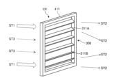
- 4 is a perspective view of a first airflow straightening section in an air supply mode according to the first embodiment;
- FIG. 5 is a perspective view of the second airflow straightening section in an air supply mode according to the first embodiment.
- FIG. 5A to 5C are diagrams for explaining a drive mechanism of a current plate according to the first embodiment.
- FIG. 2 is a vertical cross-sectional view showing the heat exchange device in an exhaust mode according to the first embodiment.
- 5 is a perspective view of a second airflow straightening portion in an exhaust mode according to the first embodiment.
- FIG. 4 is a perspective view of a first airflow straightening section in an exhaust mode according to the first embodiment.
- FIG. 11 is a perspective view of a first airflow straightening section in an air supply mode according to a second embodiment.
- FIG. 11 is a perspective view of a second airflow straightening section in an air supply mode according to a second embodiment.
- FIG. 11 is a perspective view of a second airflow straightening portion in an exhaust mode according to a second embodiment.
- FIG. 11 is a perspective view of a first airflow straightening portion in an exhaust mode according to a second embodiment.
- FIG. 11 is a perspective view of a first flow straightening portion according to a first modified example.
- FIG. 11 is a perspective view of a first airflow straightening section in an air supply mode according to a second modified example.
- FIG. 11 is a perspective view of a first airflow straightening portion in an exhaust mode according to a second modified example.
- FIG. 11 is a plan view of a lateral flow straightening plate according to a second embodiment.
- FIG. 11 is a perspective view of a lateral flow straightening plate according to a second embodiment.
- FIG. 11 is a cross-sectional view showing a heat exchange device in an air supply mode according to a third embodiment.
- FIG. 11 is a cross-sectional view showing a heat exchanger in an exhaust mode according to a third embodiment.
- FIG. 13 is a perspective view of a first airflow straightening section in an air supply mode according to the fourth embodiment.
- FIG. 13 is a perspective view of a second airflow straightening section in an air supply mode according to the fourth embodiment.
- FIG. 13 is a perspective view of a second airflow straightening portion in an exhaust mode according to the fourth embodiment.
- FIG. 13 is a perspective view of a first airflow straightening section in an exhaust mode according to the fourth embodiment.
- FIG. 11 is a perspective view of a current plate according to a third modified example.
- Fig. 1 is an overall configuration diagram of a total heat exchange ventilation system 1.
- the total heat exchange ventilation system 1 includes a heat exchanger 100 and a control device 900.
- the heat exchanger 100 is installed in a hole penetrating a wall W of a structure such as a building or a residence, and exchanges sensible heat (temperature) and latent heat (humidity) between the supply air from outside and the exhaust air from inside the room, thereby suppressing changes in temperature and humidity inside the room during ventilation.
- the control device 900 is a computer that is connected to the heat exchange device 100 via a wired or wireless connection and drives and controls the heat exchange device 100, and has a processor such as a CPU.
- the control device 900 may be equipped with an MCU (Micro Control Unit) or MPU (Micro Processor Unit), or may be equipped with an FPGA (Field Programmable Gate Array), an ASIC (Application Specific Integrated Circuit), or other computing functions.
- MCU Micro Control Unit
- MPU Micro Processor Unit
- FPGA Field Programmable Gate Array
- ASIC Application Specific Integrated Circuit
- the total heat exchange ventilation system 1 in this example has multiple (two in the example of FIG. 1) heat exchange devices 100.
- the multiple heat exchange devices 100 are provided inside the building (space portion S).
- the multiple heat exchange devices 100 include a first heat exchange device 100A and a second heat exchange device 100B.
- the first heat exchange device 100A may be one heat exchange device 100 or multiple heat exchange devices 100.
- the second heat exchange device 100B may be one heat exchange device 100 or multiple heat exchange devices 100.
- the control device 900 drives and controls each heat exchange device 100 so that when the first heat exchange device 100A is supplying air to the space S, the second heat exchange device 100B is exhausting air from the space S. Furthermore, the control device 900 drives and controls each heat exchange device 100 so that the above-mentioned supply and exhaust are switched in conjunction with each other. Specifically, the control device 900 switches the operation mode of the first heat exchange device 100A between the supply mode and the exhaust mode at a predetermined timing, and switches the operation mode of the second heat exchange device 100B between the exhaust mode and the supply mode.
- one of the first heat exchange device 100A and the second heat exchange device 100B operates in supply mode while the other operates in exhaust mode, thereby ventilating the space S.
- the first heat exchange device 100A and the second heat exchange device 100B in one of the supply mode and exhaust mode, heat and moisture are absorbed through total heat exchange with the air, and in the other mode, heat and moisture are released through total heat exchange with the air. Therefore, changes in temperature and humidity in the space S during ventilation are suppressed.
- FIG. 2 is a perspective view of the heat exchanger 100 according to the first embodiment.
- Fig. 3 is a vertical cross-sectional view of the heat exchanger 100 according to the first embodiment, seen in the X direction.
- the heat exchanger 100 is a ductless type heat exchanger including an axial fan 110, a heat exchange element 120, a pair of flow straighteners 130, and a pipe 140.
- the axial fan 110 When the axial fan 110 rotates, it generates an airflow along an axis O that passes through the center of rotation of the axial fan 110.
- the axial fan 110 is a reversible flow fan that can switch the airflow direction to the opposite side by reversing its direction of rotation.
- the heat exchange element 120 is a heat medium that has the function of exchanging total heat (sensible heat and latent heat), and is aligned with the axial fan 110 in the airflow direction.
- the pair of straightening sections 130 are members for adjusting the direction of the airflow, and are provided on both sides of the heat exchange element 120 in the airflow direction.
- the pipe 140 is a cylindrical body extending in the direction of the airflow, and houses the axial fan 110, the heat exchange element 120, and a pair of straightening sections 130.
- the direction in which the hole penetrates the wall W is defined as the Z direction.
- the pipe 140 is fitted into the hole in the wall W without any gaps so that its axial direction extends in the Z direction.
- the opening of the pipe 140 extends in the horizontal direction (X direction) and the vertical direction (Y direction).
- the openings at both ends of the pipe 140 face the indoors and outdoors.
- the pipe 140 is a square tube, but it may be another tube shape (for example, a cylindrical or triangular tube) that fits the hole in the wall W.
- the pair of straightening sections 130 consists of a first straightening section 131 and a second straightening section 132.
- the axial fan 110, the first straightening section 131, the heat exchange element 120, and the second straightening section 132 are arranged in this order from the outdoors to the indoors.
- the axis O of the axial fan 110 approximately coincides with the cross-sectional center line of the pipe 140 and extends in the Z direction so as to pass through the cross-sectional centers of the pair of straightening sections 130 and the heat exchange element 120.
- the axial fan 110, the first straightening section 131, the heat exchange element 120, and the second straightening section 132 may be arranged in this order from the indoors to the outdoors inside the pipe 140.
- the control device 900 rotates the axial fan 110 in the normal direction to generate an airflow from outdoors to indoors (airflow heading downstream in the Z direction).
- the outdoor air blown from the axial fan 110 is supplied to the heat exchanger element 120 via the first straightening section 131.
- the heat exchanger element 120 exchanges total heat with the outdoor air passing through it.
- the outdoor air that has passed through the heat exchanger element 120 flows into the room via the second straightening section 132.
- the control device 900 reverses the axial fan 110 to generate an airflow from indoors to outdoors (airflow heading upstream in the Z direction).
- the indoor air drawn into the axial fan 110 flows into the heat exchange element 120 via the second straightening section 132.
- the heat exchange element 120 exchanges total heat with the indoor air passing through it.
- the indoor air that has passed through the heat exchange element 120 is exhausted outdoors via the first straightening section 131 and the axial fan 110.
- the heat exchange element 120 has a structure in which a humidity control material is supported on a heat storage substrate.
- the humidity control material has the property of absorbing moisture when the surrounding humidity is relatively high compared to the equilibrium humidity of the material itself, and releasing moisture when the surrounding humidity is relatively low.
- desiccants such as silica gel
- the humidity control material can repeatedly absorb and release moisture, and therefore, in principle, can exert its effect semi-permanently.
- the humidity-conditioning material in this example includes a water-absorbent resin and a humidity-conditioning component (humidity-conditioning liquid) that is impregnated into the water-absorbent resin.
- the water-absorbent resin may be an ionic resin or a non-ionic resin.
- ionic resins include alkali metal salts of polyacrylic acid, starch-acrylate graft polymers, etc.
- alkali metal salts of polyacrylic acid include sodium polyacrylate, etc.
- non-ionic resins include vinyl acetate copolymers, maleic anhydride copolymers, polyvinyl alcohol, polyalkylene oxides, etc.
- the humidity control component contains at least one selected from the group consisting of deliquescent substances that absorb moisture in the air and deliquesce, and polyhydric alcohols. In this way, the humidity control effect can be further enhanced.
- polyhydric alcohols include glycerin, propanediol, butanediol, pentanediol, trimethylolpropane, butanetriol, ethylene glycol, diethylene glycol, and triethylene glycol.
- polyhydric alcohols having three or more hydroxyl groups, such as glycerin, are more preferable.
- the polyhydric alcohol may form a dimer or polymer.
- the polyhydric alcohol may contain only one of the above materials, or may contain two or more of them.
- Deliquescent substances are classified into salts and water-soluble organic substances.
- Specific examples of salts include sodium formate, potassium formate, ammonium formate, sodium acetate, potassium acetate, lithium acetate, ammonium acetate, sodium lactate, potassium lactate, sodium benzoate, potassium benzoate, sodium propionate, potassium propionate, calcium chloride, lithium chloride, magnesium chloride, calcium chloride, lithium chloride, potassium chloride, sodium chloride, zinc chloride, aluminum chloride, lithium bromide, calcium bromide, potassium bromide, sodium hydroxide, sodium pyrrolidone carboxylate, potassium carbonate, calcium citrate, sodium citrate, potassium citrate, lithium citrate, etc.
- salts only one type may be contained, or two or more types may be contained.
- sodium formate, potassium formate, sodium acetate, potassium acetate, and potassium carbonate which absorb and release a large amount of moisture per weight, are preferred.
- water-soluble organic substances include sugars such as sucrose, pullulan, glucose, xylol, fructose, mannitol, and sorbitol, carboxylic acids such as citric acid, and amides such as urea.
- the humidity control component contains a deliquescent substance
- other components may be added as additives to adjust the threshold humidity.
- Specific examples of such components include polydeliquescent substances, polyhydric alcohols, or materials that act as nucleating materials for hydrate crystals.
- Specific examples of nucleating materials include carboxylic acids with two or more carboxyl groups, and amides with two or more amide groups.
- the heat storage substrate on which the humidity-regulating material is supported is made of metal
- the metal salt may cause corrosion of the heat storage substrate. Therefore, when the heat storage substrate is made of metal, it is preferable to select a carboxylate or polyhydric alcohol as the humidity-regulating component.
- the water-absorbent resin may be in the form of a powder, particle, or block, or the water-absorbent resin may be supported on a ventilation member to efficiently contact the air.
- the heat storage substrate may be made of a material made of hydrophilic fibers, such as a porous body, nonwoven fabric, or woven fabric, in order to retain the moisture-regulating component in a moist state.
- the heat storage substrate may be made of a material made of, for example, metal (aluminum, etc.) or ceramics in order to increase the heat storage capacity in order to improve the efficiency of heat exchange with the air.
- the heat storage substrate is made of a sheet material made of the above-mentioned materials.
- this sheet material is formed into various shapes such as flat, pleated, honeycomb, etc.
- the sheet is first formed into a corrugated (fluted) shape using a corrugator.
- the formed sheet material is bonded with an adhesive to a flat liner made of the same or a different material as the sheet material, to produce an integrated heat storage substrate.
- the large number of cells formed in the heat storage substrate extend so as to penetrate the heat storage substrate in the Z direction.
- the heat exchange element 120 has a layered structure (corrugated structure) of wavy semicircular cells. Air in the pipe 140 flows through the cells, allowing it to pass through the heat exchange element 120 in the Z direction. In the manufacturing process of the heat exchange element 120, a humidity control material is attached to the inner surface of the cells. Note that the cell shape of the heat exchange element 120 is not limited to the above, and various shapes such as hexagons (honeycomb), circles, and triangles can be used.
- a honeycomb structure with an arrangement of cells of the same shape, such as hexagons is preferred.
- a large number of cells separated by porous partitions extend through the heat storage substrate in the Z direction, providing a large number of flow paths.
- a clay is first produced by kneading raw materials such as ceramic raw material powder, binder, and pore-forming material. This clay is then extruded using a screw extruder to produce a molded body having a honeycomb structure. The obtained molded body is then dried or fired to produce an integrated heat storage substrate.
- the heat storage substrate of the heat exchange element 120 is produced by stacking metal sheets made of this metal.
- This heat storage substrate has many cells formed therein, each having a minute cavity surrounded by metal sheets. This makes the heat exchange element 120 a ventilation member that circulates the air to be treated along the inner surface of the cells.
- a humidity control material is attached to the inner surface of the cell.
- the heat storage substrate of the heat exchange element 120 is metal
- a carboxylate that forms hydrate crystals is used as the humidity control component.
- the humidity control component contains a carboxylate that forms hydrate crystals and an additive that adjusts the crystallization threshold humidity. This makes it possible to freely adjust the threshold humidity while suppressing corrosion of the heat storage substrate.
- the metal heat storage substrate can exchange sensible heat (temperature) with the air in the cells
- the humidity control material can exchange latent heat (humidity) with the air in the cells.
- the contact area between the heat exchange element 120 and the air it is desirable for the contact area between the heat exchange element 120 and the air to be large. From this perspective, in order to increase the surface area of the heat storage substrate, a greater number of fine cells may be formed with a thinner metal sheet. In order to increase the surface area of the humidity control material, a greater number of humidity control materials may be attached to the inner surfaces of the cells by making the particle size of the water-absorbing resin of the humidity control material smaller.
- FIG. 4A is a vertical cross-sectional view showing the heat exchange device 100 in the air supply mode according to the first embodiment.
- Fig. 4B is a perspective view of the first rectifier 131 in the air supply mode according to the first embodiment.
- Fig. 4C is a perspective view of the second rectifier 132 in the air supply mode according to the first embodiment.
- Fig. 5 is a view for explaining the drive mechanism of the rectifier plate 300 according to the first embodiment.
- the pipe 140 is omitted, and only the horizontal rectifier plate 311 of the first rectifier 131 is illustrated, and only the horizontal rectifier plate 321 of the second rectifier 132 is illustrated.
- a pair of rectifying sections 130 are provided to suppress air speed unevenness in the heat exchange element 120.
- Each of the pair of rectifying sections 130 has a rectifying plate 300 (see Figure 3) that can be displaced to change direction, and rectifies the airflow according to the direction of the rectifying plate 300.
- the first straightening section 131 has a rectangular frame section 411 fixed to the inner circumferential surface of the pipe 140.
- two vertical frames 412 extending in the Y direction are provided symmetrically on the left and right sides with the X-direction center of the frame section 411 in between.
- two horizontal frames 413 extending in the X direction are provided symmetrically on the top and bottom sides with the Y-direction center of the frame section 411 in between.
- the square-shaped opening portion surrounded by these vertical frames 412 and horizontal frames 413 is called the central opening 131A of the first straightening section 131.
- the axis O of the axial fan 110 passes through the central opening 131A.
- the first straightening section 131 is provided with a plurality of straightening plates 300.
- the plurality of straightening plates 300 include two horizontal straightening plates 311 and two vertical straightening plates 312.
- Each horizontal straightening plate 311 is a plate for adjusting the direction of the airflow in the up-down direction (Y direction).
- Each vertical straightening plate 312 is a plate for adjusting the direction of the airflow in the left-right direction (X direction).
- the two horizontal straightening plates 311 are rectangular in shape, elongated in the X direction, and extend from the two horizontal frames 413 toward the heat exchange element 120 (downstream in the Z direction).
- the two vertical straightening plates 312 are rectangular in shape, elongated in the Y direction, and extend from the two vertical frames 412 toward the heat exchange element 120 (downstream in the Z direction).
- These four straightening plates 300 are arranged to surround the central opening 131A. In this example, each straightening plate 300 is closer to the inner surface of the pipe 140 than the axis O.
- FIG. 5 shows the movable mechanism of the lower horizontal straightening plate 311 of the two horizontal straightening plates 311.
- a support shaft 501 extending in the X direction is provided inside the lower horizontal frame 413 of the two horizontal frames 413.
- the end of the lower horizontal straightening plate 311 on the axial fan 110 side (upstream side in the Z direction) is fixed to the support shaft 501 so as to be rotatable integrally with it.
- a gear 502 is provided on the end of the support shaft 501 in the X direction.
- the gear 502 is arranged inside the vertical frame 412, and is connected to a gear 503 below it by a belt 504.
- Gear 503 is fixed to the shaft of a motor that is driven to rotate by control device 900.
- control device 900 rotates this motor, the rotation of gear 503 is transmitted to gear 502 via belt 504, and lateral straightening plate 311 rotates around support shaft 501.
- lateral straightening plate 311 can be displaced between a normal position (see FIG. 6C) extending substantially horizontally and an inclined position (see FIG. 4B) inclined toward axis O.
- lateral straightening plate 311 is inclined diagonally backward so that end 3110 on the heat exchange element 120 side (downstream side in the Z direction) approaches axis O.
- the other straightening plates 300 can also be rotated by a mechanism similar to that shown in FIG. 5.
- the vertical straightening plate 312 in this example can be displaced between a normal position extending substantially vertically (see FIG. 6C) and an inclined position inclined toward the axis O (see FIG. 4B).
- the drive mechanism for the straightening plate 300 is not limited to the example shown in FIG. 5, and any mechanism can be used as long as it can displace the straightening plate 300 between the normal position and the inclined position.
- the second straightening section 132 like the first straightening section 131, has a rectangular frame section 421, and two vertical frames 422 and two horizontal frames 423 are provided at the opening of the frame section 421.
- the square-shaped opening portion surrounded by these vertical frames 422 and horizontal frames 423 is called the central opening 132A of the second straightening section 132.
- the axis O of the axial fan 110 passes through the central opening 132A.
- the second straightening section 132 like the first straightening section 131, has multiple straightening plates 300 (two horizontal straightening plates 321 and two vertical straightening plates 322).
- the two horizontal straightening plates 321 extend from the two horizontal frames 423 toward the heat exchange element 120 (upstream side in the Z direction).
- the two vertical straightening plates 322 extend from the two vertical frames 422 toward the heat exchange element 120 (upstream side in the Z direction).
- These four straightening plates 300 are arranged to surround the central opening 132A.
- each straightening plate 300 is closer to the axis O than the inner surface of the pipe 140. Therefore, the central opening 132A of the second straightening section 132 is smaller than the central opening 131A of the first straightening section 131, and the entire central opening 132A is arranged inside the central opening 131A when viewed from the Z direction.
- the straightening plates 300 of the second straightening section 132 can also rotate by a mechanism similar to that shown in FIG. 5. However, the straightening plates 300 of the second straightening section 132 can rotate so that the end of each straightening plate 300 on the heat exchange element 120 side approaches the inner circumferential surface of the pipe 140 (the outer portion of the pipe 140).
- the horizontal straightening plate 321 can be displaced between a normal position extending substantially horizontally (see FIG. 4C) and an inclined position inclined toward the inner circumferential surface of the pipe 140 (see FIG. 6B).
- the vertical straightening plate 322 can be displaced between a normal position extending substantially vertically (see FIG. 4C) and an inclined position inclined toward the inner circumferential surface of the pipe 140 (see FIG. 6B).
- each of the pair of rectifiers 130 (first rectifier 131 and second rectifier 132) changes the orientation of the rectifier plate 300 depending on the airflow direction being switched in the axial fan 110.
- the pair of rectifiers 130 are composed of an upstream rectifier located upstream of the heat exchange element 120 in the airflow direction, and a downstream rectifier located downstream of the heat exchange element.
- the first rectifier 131 is the upstream rectifier
- the second rectifier 132 is the downstream rectifier.
- the first rectifier 131 is the downstream rectifier
- the second rectifier 132 is the upstream rectifier.
- the upstream straightening section changes the orientation of the straightening plate 300 so that the straightening plate 300 diffuses part of the airflow radially inward or radially outward from the axis O of the axial fan 110.
- the downstream straightening section changes the orientation of the straightening plate 300 so that the area of the straightening plate 300 facing the airflow is reduced.
- Air supply mode driving mode 4A in the heat exchange device 100 in the air supply mode, an airflow (airflow directed downstream in the Z direction) from the outdoors to the indoors is generated by the forward rotation of the axial fan 110. At this time, the wind speed of the airflow sent by the axial fan 110 toward the heat exchange element 120 increases from the axis O toward the inner circumferential surface of the pipe 140. Therefore, on the first surface 121 of the heat exchange element 120 facing the axial fan 110, a high-speed airflow ST1 is supplied to the inner circumferential surface side of the pipe 140, while a low-speed airflow ST3 is supplied to the center side (axis O side) of the pipe 140, which may cause uneven wind speed.
- the upstream rectifier changes the orientation of the rectifier plate 300 so that the rectifier plate 300 approaches the axis O the further downstream in the airflow direction, and so that the angle between the rectifier plate 300 and the axis O is 45 degrees or less.
- the downstream rectifier changes the orientation of the rectifier plate 300 so that the rectifier plate 300 is parallel to the axis O.
- the control device 900 displaces each rectifier plate 300 of the first rectifier plate 131 to an inclined position and displaces each rectifier plate 300 of the second rectifier plate 132 to a normal position.
- the rectifier plate 300 in the inclined position is rotated, for example, 30 degrees from the normal position.
- the multiple straightening plates 300 (horizontal straightening plates 311 and vertical straightening plates 312) are all inclined radially inward of the axis O toward the heat exchange element 120 side (downstream side in the Z direction).
- the airflow supplied from the axial fan 110 diffuses radially inward of the axis O along each straightening plate 300.
- the vertical direction (Y direction) of the airflow is adjusted to face the center side of the pipe 140 along the horizontal straightening plate 311, and the vertical direction (Y direction) of the airflow is adjusted to face the center side of the pipe 140 along the vertical straightening plate 312.
- the flow rate and flow speed of the airflow are improved on the center side of the pipe 140 where the low-speed airflow ST3 flows.
- each straightening plate 300 can smoothly guide the airflow flowing in the Z direction and suppress a decrease in the flow speed of the airflow.
- each straightening plate 300 is closer to the inner surface of the pipe 140 than to the axis O. Therefore, each straightening plate 300 can reliably come into contact with the high-speed airflow ST1 flowing along the inner surface of the pipe 140 and diffuse the airflow ST1 radially inward from the axis O.
- the airflow passing through the first straightening section 131 and heading toward the heat exchange element 120 is supplied to the entire first surface 121 at a substantially uniform wind speed.
- This medium-speed airflow ST2 is totally heat exchanged as it passes through the heat exchange element 120, and is discharged from the second surface 122 of the heat exchange element 120.
- the airflow ST2 discharged from the second surface 122 passes through the second straightening section 132 and is supplied to the room.
- each straightening plate 300 displaced to its normal position extends substantially parallel to the Z direction. Therefore, the airflow ST2 passing through the second straightening section 132 can smoothly flow out toward the room because the decrease in flow speed due to contact with each straightening plate 300 is suppressed.
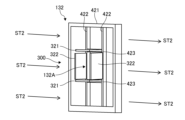
- FIG. 6A is a vertical cross-sectional view showing the heat exchange device 100 in the exhaust mode according to the first embodiment.
- Fig. 6B is a perspective view of the second flow straightening unit 132 in the exhaust mode according to the first embodiment.
- Fig. 6C is a perspective view of the first flow straightening unit 131 in the exhaust mode according to the first embodiment.
- the axial fan 110 reverses its rotation to generate an airflow from the room to the outside (airflow heading upstream in the Z direction).
- the wind speed of the airflow heading from the room to the heat exchange element 120 due to the suction force of the axial fan 110 decreases from the axis O toward the inner surface of the pipe 140. Therefore, on the second surface 122 of the heat exchange element 120 facing the opposite side to the axial fan 110, a high-speed airflow ST1 is supplied to the center side of the pipe 140 (the axis O side), while a low-speed airflow ST3 is supplied to the inner surface side of the pipe 140, which may cause uneven wind speed.
- the upstream rectifier changes the orientation of the rectifier plate 300 so that the rectifier plate 300 moves away from the axis O the further downstream in the airflow direction, and so that the angle between the rectifier plate 300 and the axis O is 45 degrees or less.
- the downstream rectifier changes the orientation of the rectifier plate 300 so that the rectifier plate 300 is parallel to the axis O.
- the control device 900 displaces each rectifier plate 300 of the first rectifier plate 131 to the normal position and displaces each rectifier plate 300 of the second rectifier plate 132 to the inclined position.
- the rectifier plate 300 in the inclined position is rotated, for example, 30 degrees from the normal position.
- the plurality of straightening plates 300 (horizontal straightening plate 321 and vertical straightening plate 322) are all inclined radially outward of the axis O toward the heat exchange element 120 side (upstream side in the Z direction).
- the airflow sucked by the axial fan 110 diffuses radially outward of the axis O along each straightening plate 300.
- the vertical direction (Y direction) of the airflow is adjusted to face the inner circumferential surface side of the pipe 140 along the horizontal straightening plate 321, and the vertical direction (Y direction) of the airflow is adjusted to face the inner circumferential surface side of the pipe 140 along the vertical straightening plate 322.
- the flow rate and flow speed of the airflow are improved on the inner circumferential surface side of the pipe 140 where the low-speed airflow ST3 flows.
- each straightening plate 300 can smoothly guide the airflow flowing in the Z direction and suppress a decrease in the flow speed of the airflow.
- each straightening plate 300 is closer to the axis O than the inner surface of the pipe 140. Therefore, each straightening plate 300 can reliably come into contact with the high-speed airflow ST1 flowing along the axis O and diffuse the airflow ST1 radially outward from the axis O.
- the airflow passing through the second straightening section 132 and heading toward the heat exchange element 120 is supplied to the entire second surface 122 at a substantially uniform wind speed.
- This medium-speed airflow ST2 is totally heat exchanged when passing through the heat exchange element 120, and is discharged from the first surface 121 of the heat exchange element 120.
- the airflow ST2 discharged from the first surface 121 passes through the first straightening section 131 and the axial fan 110 and is exhausted to the outdoors.
- each straightening plate 300 displaced to the normal position extends substantially parallel to the Z direction. Therefore, the airflow ST2 passing through the first straightening section 131 can smoothly flow out toward the outdoors because the decrease in flow speed due to contact with each straightening plate 300 is suppressed.
- FIG. 7A is a perspective view of a first straightening section 131 in the supply mode according to the second embodiment.
- Fig. 7B is a perspective view of a second straightening section 132 in the supply mode according to the second embodiment.
- Fig. 8A is a perspective view of a second straightening section 132 in the exhaust mode according to the second embodiment.
- Fig. 8B is a perspective view of a first straightening section 131 in the exhaust mode according to the second embodiment.
- the first straightening section 131 has a frame portion 411 and multiple straightening plates 300, as in the first embodiment.
- the multiple straightening plates 300 include multiple horizontal straightening plates 311A, 311B, and do not include a vertical straightening plate 312 (see FIG. 4B).
- Each horizontal straightening plate 311A, 311B has a rectangular shape extending in the X direction through the inner opening of the frame portion 411, and both ends are supported by the vertical frame of the frame portion 411.
- the multiple (three in this example) horizontal straightening plates 311A are arranged at intervals from each other from the center of the opening of the frame portion 411 toward the upper side.
- the multiple (three in this example) horizontal straightening plates 311B are arranged at intervals from each other from the center of the opening of the frame portion 411 toward the lower side.
- Each horizontal straightening plate 311A, 311B can be displaced between a normal position (see FIG. 8B) extending substantially horizontally and an inclined position (see FIG. 7A) inclined toward the axis O.
- a normal position see FIG. 8B
- an inclined position see FIG. 7A
- the multiple horizontal straightening plates 311A are displaced from the normal position to the inclined position, they all incline diagonally downward.
- the multiple horizontal straightening plates 311B are displaced from the normal position to the inclined position, they all incline diagonally upward.
- the inclination angle of these straightening plates 300 (horizontal straightening plates 311A, 311B) with respect to the axis O is 45 degrees or less.
- the second straightening section 132 like the first straightening section 131 described above, has a frame portion 421 and multiple straightening plates 300 (multiple horizontal straightening plates 321A, 321B).
- Each horizontal straightening plate 321A, 321B is displaceable between a normal position extending substantially horizontally (see FIG. 8A) and an inclined position inclined toward the axis O (see FIG. 7B).
- the control device 900 displaces each straightening plate 300 of the first straightening section 131 to an inclined position, and displaces each straightening plate 300 of the second straightening section 132 to a normal position.
- the vertical direction of the airflow (Y direction) is adjusted along each straightening plate 300, so that the airflow is supplied radially inward of the axis O c, at a substantially uniform wind speed over the entire first surface 121.
- each straightening plate 300 extends substantially parallel to the Z direction, so that a decrease in the flow speed of the airflow is suppressed, and the airflow can flow smoothly toward the room.
- each straightening plate 300 of the first straightening section 131 when the exhaust mode is executed, the control device 900 displaces each straightening plate 300 of the first straightening section 131 to a normal position, and displaces each straightening plate 300 of the second straightening section 132 to an inclined position.
- the vertical direction of the airflow (Y direction) is adjusted along each straightening plate 300, so that the airflow is diffused radially outward from the axis O and is supplied to the entire second surface 122 at a substantially uniform wind speed.
- each straightening plate 300 extends substantially parallel to the Z direction, so that a decrease in the flow speed of the airflow is suppressed, and the airflow can flow smoothly toward the outdoors.
- the frame 411 of the rectifier 130 is not limited to a rectangular frame shape, and various shapes can be adopted corresponding to the hole to which the rectifier 130 is attached.
- the multiple rectifier plates 300 are not limited to being the same shape or size, and may be different shapes or sizes.
- Figure 9 is an oblique view of the first rectifier 131 according to the first modified example.
- the frame 411 is a circular frame shape, and the left and right lengths of the multiple rectifier plates 300 decrease the further away from the center of the opening of the frame 411.
- the straightening plate 300 of the straightening section 130 is not limited to a flat plate shape, and various shapes can be adopted.
- Fig. 10A is a perspective view of the first straightening section 131 in the air supply mode according to the second modified example.
- Fig. 10B is a perspective view of the second straightening section 132 in the air supply mode according to the second modified example.
- Fig. 10B is a perspective view of the first straightening section 131 in the exhaust mode according to the second modified example.
- the first straightening section 131 of the second modified example has a frame portion 411 and a plurality of straightening plates 300 (not shown).
- the plurality of straightening plates 300 includes a set of an upper straightening plate 1011 and a lower straightening plate 1012.
- the upper straightening plate 1011 is a semicircular curved plate that protrudes upward when viewed from the Z direction.
- the upper straightening plate 1011 is a semicircular curved plate that protrudes downward when viewed from the Z direction.
- a cylinder 1001 that penetrates in the Z direction is supported at the center of the inner opening of the frame portion 411.
- the upper straightening plate 1011 and the lower straightening plate 1012 are arranged vertically on the outer periphery of the cylinder 1001, and are supported rotatably by the cylinder 1001.
- the upper straightening plate 1011 and the lower straightening plate 1012 are stacked vertically in a horizontal position, forming a cylindrical shape extending in the Z direction as a whole.
- the upper straightening plate 1011 and the lower straightening plate 1012 extend substantially parallel to the Z direction, so that a decrease in the flow rate of the airflow is suppressed, and the air can flow smoothly outdoors.
- FIG. 11A is a plan view of the horizontal straightening plate 311A according to the second embodiment.
- FIG. 11B is a perspective view of the horizontal straightening plate 311A according to the second embodiment.
- FIG. 12 is a cross-sectional view showing the heat exchanger 100 in the supply mode according to the third embodiment.
- FIG. 13 is a cross-sectional view showing the heat exchanger 100 in the exhaust mode according to the third embodiment.
- each of the multiple horizontal straightening plates 311A provided in the first straightening section 131 has a slat 1101 and multiple fins 1102, 1103.
- the slat 1101 is the plate body of the horizontal straightening plate 311A and extends radially outward from a rotation center line C that is perpendicular to the airflow direction.
- the rotation center line C passes through an axis that supports the rotation of the slat 1101.
- the multiple fins 1102, 1103 extend upright from the surface of the slat 1101 in a direction that intersects with the rotation center line C.
- three fins 1102 and three fins 1103 are provided symmetrically on both sides of the axis O in each horizontal straightening plate 311A.
- the rotation center line C extends in the X direction perpendicular to the airflow direction (Z direction).
- the three fins 1102 are inclined toward the axis O (upper right side in FIG. 11A) toward the heat exchange element 120 (downstream side in the Z direction).
- the three fins 1103 are inclined toward the axis O (upper left side in FIG. 11A) toward the heat exchange element 120 (downstream side in the Z direction).
- the inclination angle of each fin 1102, 1103 with respect to the axis O is 45 degrees or less.
- the multiple horizontal straightening plates 311B also have multiple fins 1102, 1103 provided on the slat 1101. That is, in the straightening plate 300 (horizontal straightening plates 311A, 311B) of the first straightening section 131, each fin 1102, 1103 extends closer to the rotation center line C the further downstream it is in the airflow direction (downstream in the Z direction) in the air supply mode.
- each fin 1102, 1103 of the straightening plate 300 extends farther away from the rotation center line C toward the downstream side of the airflow direction in exhaust mode (upstream side in the Z direction) (see Figures 12 and 13).
- a central gap 1104 is formed between the multiple fins 1202 and the multiple fins 1203, through which the axis O passes in a planar view.
- the width (length in the X direction) of the central gap 1104 is the sum of the shortest distance L1 from the axis O to the multiple fins 1102 in a planar view and the shortest distance L2 from the axis O to the multiple fins 1103 in a planar view.
- the width of the central gap 1104 is larger in the straightening plate 300 of the first straightening section 131 than in the straightening plate 300 of the second straightening section 132 (see Figures 12 and 13).
- the airflow is adjusted in the vertical direction (Y direction) along the slats 1101 of each straightening plate 300, and the airflow is diffused radially inward of the axis O. Furthermore, as shown in FIG. 12, the airflow is adjusted in the horizontal direction (X direction) along the fins 1102, 1103 of each straightening plate 300, and the airflow is diffused radially inward of the axis O.
- the airflow is adjusted in the vertical direction (Y direction) along the slats 1101 of each straightening plate 300, and the airflow is diffused radially outward of the axis O.
- the airflow is adjusted in the horizontal direction (X direction) along the fins 1102, 1103 of each straightening plate 300, and the airflow is guided radially outward of the axis O.
- each straightening plate 300 can smoothly guide the airflow flowing in the Z direction, suppressing a decrease in the flow speed of the airflow.
- the first straightening section 131 has a large central gap 1104, so the multiple fins 1102, 1103 are arranged biased toward the inner circumferential surface of the pipe 140.
- Each fin 1102, 1103 of the first straightening section 131 reliably contacts the high-speed airflow ST1 flowing along the inner circumferential surface of the pipe 140, and can diffuse the airflow ST1 radially inward of the axis O.
- the second straightening section 132 has a small central gap 1104, so the multiple fins 1102, 1103 are arranged biased toward the center of the pipe 140.
- Each fin 1102, 1103 of the second straightening section 132 reliably contacts the high-speed airflow ST1 flowing along the center of the pipe 140, and can diffuse the airflow ST1 radially outward of the axis O.
- fins 1102, 1103 for adjusting the airflow direction in the up-down direction (Y direction) may be provided on the airflow straightening plate 300 (e.g., vertical airflow straightening plates 312, 322) for adjusting the airflow direction in the left-right direction (X direction).
- the left-right direction (X direction) of the airflow is adjusted along the slats 1101, and further the up-down direction (Y direction) of the airflow is adjusted along the fins 1102, 1103, so that the airflow can be diffused radially inward or outward from the axis O.
- FIG. 14A is a perspective view of the first straightening part 131 in the air supply mode according to the fourth embodiment.
- FIG. 14B is a perspective view of the second straightening part 132 in the air supply mode according to the fourth embodiment.
- FIG. 15A is a perspective view of the second straightening part 132 in the exhaust mode according to the fourth embodiment.
- FIG. 15B is a perspective view of the first straightening part 131 in the exhaust mode according to the fourth embodiment.
- the drive mechanism of the straightening plate 300 is omitted.
- one straightening plate 300 is rotatably supported at the inner opening of the frame section 411.
- the straightening plate 300 has a plurality of openings 1400 penetrating in the thickness direction.
- the opening areas of the plurality of openings 1400 decrease the farther they are from the axis O.
- the second straightening section 132 of the fourth embodiment has the same configuration as the first straightening section 131, but differs in that the opening areas of the plurality of openings 1400 increase the farther they are from the axis O. The larger the opening area of the opening 1400, the smaller the airflow resistance, and vice versa.
- the straightening plate 300 of the first straightening section 131 is fixed to a shaft 1501 that extends vertically through the inner opening of the frame section 411.
- a gear 1502 is fixed to one end of the shaft 1501, and the gear 1502 meshes with a gear 1503 of a motor.
- the straightening plate 300 rotates and is displaced to the inclined position and the normal position.
- the straightening plate 300 extends perpendicular to the direction of the airflow (Z direction) and closes the inner opening of the frame section 411.
- Z direction the direction of the airflow
- the straightening plate 300 when the straightening plate 300 is displaced to the normal position, the straightening plate 300 extends parallel to the direction of the airflow (Z direction) and opens the inner opening of the frame section 411.
- the straightening plate 300 of the second straightening section 132 is also displaced to the inclined position and the normal position by a similar mechanism.
- the straightening plate 300 may have a structure in which two blades are connected by a hinge, and the two blades may open and close in response to the rotation of the motor.
- the straightening plate 300 when the two blades are folded closed in response to the rotation of the motor, the straightening plate 300 extends parallel to the direction of the airflow (Z direction) as shown in FIG. 16B, opening the inside of the frame portion 411.
- the straightening plate 300 extends perpendicular to the direction of the airflow (Z direction) as shown in FIG. 15A, closing the inner opening of the frame portion 411.
- the control device 900 displaces the straightening plate 300 of the first straightening section 131 to an inclined position (see FIG. 14A), and displaces the straightening plate 300 of the second straightening section 132 to a normal position (see FIG. 15A and FIG. 15B).
- the high-speed airflow ST1 flowing along the inner circumferential surface side of the pipe 140 passes through the opening 1400 with a small opening area, and therefore the flow speed is likely to decrease.
- the low-speed airflow ST3 flowing along the center side of the pipe 140 passes through the opening 1400 with a large opening area, and therefore the flow speed is not likely to decrease.
- the airflow passing through the straightening plate 300 of the first straightening section 131 is diffused from the inner circumferential surface side of the pipe 140 to the center side.
- the airflow passing through the first straightening section 131 is supplied to the entire first surface 121 of the heat exchange element 120 at a substantially uniform wind speed.
- the straightening plate 300 extends substantially parallel to the Z direction, so a decrease in the flow speed of the airflow is suppressed.
- the control device 900 displaces the straightening plate 300 of the first straightening section 131 to the normal position (see Figs. 15A and 15B), and displaces the straightening plate 300 of the second straightening section 132 to the inclined position (see Fig. 14B).
- the high-speed airflow ST1 flowing on the center side of the pipe 140 passes through the opening 1400 with a small opening area, and so the flow speed is likely to decrease.
- the low-speed airflow ST3 flowing on the inner surface side of the pipe 140 passes through the opening 1400 with a large opening area, and so the flow speed is not likely to decrease.
- the airflow passing through the straightening plate 300 of the second straightening section 132 is diffused from the center side of the pipe 140 to the inner surface side.
- the airflow that has passed through the second straightening section 132 is supplied to the entire second surface 122 of the heat exchange element 120 at a substantially uniform wind speed.
- the straightening plate 300 extends substantially parallel to the Z direction, so a decrease in the flow speed of the airflow is suppressed.
- FIG. 16 is a perspective view of a straightening plate 300 according to a third modified example.
- each of the multiple openings 1400 extends in a semicircular arc shape centered on the axis O. Since the straightening plate 300 in Figure 16 is used in the first straightening section 131, the multiple openings 1400 have a smaller opening width the farther they are from the axis O. When the straightening plate 300 is used in the second straightening section 132, the multiple openings 1400 have a larger opening width the farther they are from the axis O.
- a large number of fine cells may be formed in a thin metal sheet heat storage substrate in the heat exchange element 120.
- the surface area (i.e., the contact area with air) of the heat exchange element 120 can be increased to improve the heat exchange efficiency, but the thin heat storage substrate may result in a decrease in heat storage capacity.
- the straightening plates 300 of the pair of straightening sections 130 are made of metal, and latent heat storage material is attached to the straightening plates 300.
- heat exchange is also possible in the pair of straightening sections 130, so the overall heat storage capacity of the heat exchange device 100 can be increased. Also, because heat exchange is possible in one of the pair of straightening sections 130 before the air flows into the heat exchange element 120, the exchange efficiency of sensible heat and latent heat is improved.
- Latent heat storage materials are materials that store latent heat exchanged with the outside during a phase change or transition of a substance as thermal energy.
- Latent heat storage materials utilize the heat of fusion and solidification at their melting points.
- Latent heat storage materials involve a phase change between solid and liquid.
- Latent heat storage materials store heat at the phase change temperature, so they can store heat in a boundary region (i.e., store heat at a constant temperature). This principle is based on the phenomenon that as long as two layers of solid and liquid are mixed during a phase change, heat is continuously taken from the outside, so the temperature does not rise above the melting point.
- the melting point of the latent heat storage material is 10 to 35°C, and 20 to 35°C is preferable. If the melting point is in the range of 10 to 35°C, the latent heat storage material can effectively store heat when the heat exchange device 100 exchanges heat between indoor air and outdoor air as a total heat exchanger.
- latent heat storage materials include fatty acids such as palmitic acid and myristic acid, aromatic hydrocarbon compounds such as benzene and p-xylene, ester compounds such as isopropyl palmitate, butyl stearate, stearyl stearate, and myristyl myristate, alcohols such as stearyl alcohol and glycerol, d-lactic acid, acetic acid, capric acid, and ethylenediamine.
- aliphatic hydrocarbons include paraffins. Paraffins include linear and branched paraffins, with linear n-paraffins being preferred.
- n-paraffins examples include n-pentadecane, n-hexadecane, n-heptadecane, n-octadecane, and n-nonadecane.
- hydrates include Zn(NO3)2.6H20, NaHPO4.12H20, Na2CO3.10H20, Na2SO4.10H20, Li2NO3.3H20, Ca2Cl2.6H20, Ca2CO3.10H20, and FeBr3.6H20.
- These latent heat storage components may be used alone or in combination of two or more. It is preferable to use a chemically and physically stable and inexpensive substance as the latent heat storage component.
- the aqueous humidity control material is supported on the heat exchange element 120, while the hydrophobic latent heat storage material is supported on the straightening plate 300, which is the sensible heat exchange section. Therefore, in the heat exchange device 100, it is possible to control and support the aqueous humidity control material and the hydrophobic latent heat storage material independently, improving the production efficiency of the heat exchange device 100.
- the humidity control material and the latent heat storage material can each be supported on the optimal substrate.
- the latent heat storage material may be affected by the exchange of moisture with the humidity control component.
- the hydrate salts and the humidity control component are not mixed, and total heat exchange is performed in a state in which the latent heat storage material is continuously present on the heat storage substrate in the straightening plate 300, making it possible to control each of them.
- the temperature control agent in which the latent heat storage material is held in a gel-like resin may be supported on the rectifying plate 300, which is the sensible heat exchanger.
- the fluidity of the latent heat storage material is improved and a larger heat storage capacity can be held in the rectifying plate 300.
- the temperature control agent in which the latent heat storage material is encapsulated in microcapsules may be supported on the sensible heat exchanger. In this case, since the latent heat storage material undergoes a phase change in the microcapsules, the fluidity of the latent heat storage material is improved and a larger heat storage capacity can be held in the rectifying plate 300.
- the multiple straightening plates 300 in each straightening section 130 can be adopted for the number and shape of the multiple straightening plates 300 in each straightening section 130.
- multiple horizontal straightening plates 321 may be arranged on both the top and bottom sides of the axis O, or multiple vertical straightening plates 322 may be arranged on both the left and right sides of the axis O.
- the multiple straightening plates 300 may be composed of three or more curved plates (for example, four curved plates on the top, bottom, left and right).
- the inclination angle of each straightening plate 300 may be different.
- the inclination angle of the straightening plate 300 on the center side of the pipe 140 may be small, and the inclination angle of the straightening plate 300 on the inner surface side of the pipe 140 may be large.
Landscapes
- Engineering & Computer Science (AREA)
- Mechanical Engineering (AREA)
- General Engineering & Computer Science (AREA)
- Chemical & Material Sciences (AREA)
- Combustion & Propulsion (AREA)
- Physics & Mathematics (AREA)
- Thermal Sciences (AREA)
- Dispersion Chemistry (AREA)
- Life Sciences & Earth Sciences (AREA)
- Sustainable Development (AREA)
- Heat-Exchange Devices With Radiators And Conduit Assemblies (AREA)
Priority Applications (3)
| Application Number | Priority Date | Filing Date | Title |
|---|---|---|---|
| JP2024576138A JPWO2024166509A1 (https=) | 2023-02-08 | 2023-12-01 | |
| CN202380093376.9A CN120659957A (zh) | 2023-02-08 | 2023-12-01 | 热交换装置及全热交换换气系统 |
| EP23921329.1A EP4664024A4 (en) | 2023-02-08 | 2023-12-01 | HEAT EXCHANGER AND TOTAL HEAT EXCHANGE VENTILATION SYSTEM |
Applications Claiming Priority (2)
| Application Number | Priority Date | Filing Date | Title |
|---|---|---|---|
| JP2023017213 | 2023-02-08 | ||
| JP2023-017213 | 2023-02-08 |
Publications (1)
| Publication Number | Publication Date |
|---|---|
| WO2024166509A1 true WO2024166509A1 (ja) | 2024-08-15 |
Family
ID=92262960
Family Applications (1)
| Application Number | Title | Priority Date | Filing Date |
|---|---|---|---|
| PCT/JP2023/043064 Ceased WO2024166509A1 (ja) | 2023-02-08 | 2023-12-01 | 熱交換装置及び全熱交換換気システム |
Country Status (4)
| Country | Link |
|---|---|
| EP (1) | EP4664024A4 (https=) |
| JP (1) | JPWO2024166509A1 (https=) |
| CN (1) | CN120659957A (https=) |
| WO (1) | WO2024166509A1 (https=) |
Cited By (1)
| Publication number | Priority date | Publication date | Assignee | Title |
|---|---|---|---|---|
| GB2641034A (en) * | 2024-05-13 | 2025-11-19 | Volution Ventilation Group Ltd | Ventilation heat recovery unit |
Citations (9)
| Publication number | Priority date | Publication date | Assignee | Title |
|---|---|---|---|---|
| US4700550A (en) * | 1986-03-10 | 1987-10-20 | Rhodes Barry V | Enthalpic heat pump desiccant air conditioning system |
| US4799539A (en) * | 1985-03-12 | 1989-01-24 | Advanced Design & Manufacture Limited | Thermally efficient room ventilator |
| JPH04227433A (ja) * | 1990-05-15 | 1992-08-17 | Berner Erling | 換気及び熱交換装置 |
| JP2013113463A (ja) | 2011-11-28 | 2013-06-10 | Passiv Energie Japan Inc | 蓄熱エレメント及びそれを用いた換気ユニット |
| JP2018059692A (ja) * | 2016-10-07 | 2018-04-12 | マルヤス工業株式会社 | 全熱交換器 |
| JP2019015490A (ja) * | 2017-07-03 | 2019-01-31 | クリスティアン ドイティンガー | ファンユニット |
| CN209877213U (zh) * | 2019-03-01 | 2019-12-31 | 青岛海尔空调器有限总公司 | 一种穿墙式双向新风装置 |
| CN115540131A (zh) * | 2021-06-29 | 2022-12-30 | 斯德龙有限两合公司 | 一种分散式新风装置和流体整流器 |
| JP2023017213A (ja) | 2021-07-26 | 2023-02-07 | セイコーエプソン株式会社 | 記録システム |
Family Cites Families (4)
| Publication number | Priority date | Publication date | Assignee | Title |
|---|---|---|---|---|
| US4952283A (en) * | 1988-02-05 | 1990-08-28 | Besik Ferdinand K | Apparatus for ventilation, recovery of heat, dehumidification and cooling of air |
| US5230719A (en) * | 1990-05-15 | 1993-07-27 | Erling Berner | Dehumidification apparatus |
| JP2006284021A (ja) * | 2005-03-31 | 2006-10-19 | Nitta Ind Corp | 換気式熱交換器、及び換気式熱交換器ユニット |
| JP7051489B2 (ja) * | 2018-02-26 | 2022-04-11 | クリスティアン ドイティンガー | 換気システム |
-
2023
- 2023-12-01 EP EP23921329.1A patent/EP4664024A4/en active Pending
- 2023-12-01 CN CN202380093376.9A patent/CN120659957A/zh active Pending
- 2023-12-01 WO PCT/JP2023/043064 patent/WO2024166509A1/ja not_active Ceased
- 2023-12-01 JP JP2024576138A patent/JPWO2024166509A1/ja active Pending
Patent Citations (9)
| Publication number | Priority date | Publication date | Assignee | Title |
|---|---|---|---|---|
| US4799539A (en) * | 1985-03-12 | 1989-01-24 | Advanced Design & Manufacture Limited | Thermally efficient room ventilator |
| US4700550A (en) * | 1986-03-10 | 1987-10-20 | Rhodes Barry V | Enthalpic heat pump desiccant air conditioning system |
| JPH04227433A (ja) * | 1990-05-15 | 1992-08-17 | Berner Erling | 換気及び熱交換装置 |
| JP2013113463A (ja) | 2011-11-28 | 2013-06-10 | Passiv Energie Japan Inc | 蓄熱エレメント及びそれを用いた換気ユニット |
| JP2018059692A (ja) * | 2016-10-07 | 2018-04-12 | マルヤス工業株式会社 | 全熱交換器 |
| JP2019015490A (ja) * | 2017-07-03 | 2019-01-31 | クリスティアン ドイティンガー | ファンユニット |
| CN209877213U (zh) * | 2019-03-01 | 2019-12-31 | 青岛海尔空调器有限总公司 | 一种穿墙式双向新风装置 |
| CN115540131A (zh) * | 2021-06-29 | 2022-12-30 | 斯德龙有限两合公司 | 一种分散式新风装置和流体整流器 |
| JP2023017213A (ja) | 2021-07-26 | 2023-02-07 | セイコーエプソン株式会社 | 記録システム |
Non-Patent Citations (1)
| Title |
|---|
| See also references of EP4664024A4 |
Cited By (1)
| Publication number | Priority date | Publication date | Assignee | Title |
|---|---|---|---|---|
| GB2641034A (en) * | 2024-05-13 | 2025-11-19 | Volution Ventilation Group Ltd | Ventilation heat recovery unit |
Also Published As
| Publication number | Publication date |
|---|---|
| EP4664024A4 (en) | 2026-04-29 |
| EP4664024A1 (en) | 2025-12-17 |
| CN120659957A (zh) | 2025-09-16 |
| JPWO2024166509A1 (https=) | 2024-08-15 |
Similar Documents
| Publication | Publication Date | Title |
|---|---|---|
| CN114256535B (zh) | 基于相变材料和互嵌式肋片的锂离子电池热管理系统及方法 | |
| WO2024166509A1 (ja) | 熱交換装置及び全熱交換換気システム | |
| JPWO2024166509A5 (https=) | ||
| CN1182351C (zh) | 两壁间传热装置 | |
| WO2023248560A1 (ja) | 全熱交換素子及び換気装置 | |
| CN109149002B (zh) | 一种用于电池的全气候热管理系统及其工作方法 | |
| CN221523888U (zh) | 一种相变式蓄热墙 | |
| JP6309087B2 (ja) | 冷却装置 | |
| CN116607698B (zh) | 一种装配式建筑节能型保温墙体结构 | |
| CN110685374A (zh) | 一种能够进行室内外热交换的建筑保温墙体 | |
| ES3035950T3 (en) | Thermal structure for buildings | |
| CN211830708U (zh) | 一种户外防护型太阳能光伏板储能装置 | |
| WO2022039149A1 (ja) | 水集積装置、及び水集積方法 | |
| CN210737836U (zh) | 一种升降式相变储能墙体 | |
| KR102020552B1 (ko) | 공기조화기의 기울기 조절이 가능한 히트파이프 폐열회수 열교환시스템 | |
| CN210976148U (zh) | 一种活动式相变储能墙体 | |
| CN102468351A (zh) | 安装在建筑物上的太阳能系统 | |
| WO2025197658A1 (ja) | 調湿エレメント及び全熱交換装置 | |
| WO2026053574A1 (ja) | 熱交換換気装置 | |
| CN214574760U (zh) | 一种改良型复合浪板 | |
| CN214170075U (zh) | 一种能够快速散热型的风机房 | |
| WO2024252775A1 (ja) | 熱交換型換気装置及び全熱交換換気システム | |
| WO2025089059A1 (ja) | 全熱交換ユニット | |
| WO2024111327A1 (ja) | 全熱交換器及び換気装置 | |
| CN209694465U (zh) | 一种电子除湿装置及系统 |
Legal Events
| Date | Code | Title | Description |
|---|---|---|---|
| 121 | Ep: the epo has been informed by wipo that ep was designated in this application |
Ref document number: 23921329 Country of ref document: EP Kind code of ref document: A1 |
|
| WWE | Wipo information: entry into national phase |
Ref document number: 2024576138 Country of ref document: JP |
|
| WWE | Wipo information: entry into national phase |
Ref document number: 2501005199 Country of ref document: TH Ref document number: 202380093376.9 Country of ref document: CN |
|
| NENP | Non-entry into the national phase |
Ref country code: DE |
|
| WWP | Wipo information: published in national office |
Ref document number: 202380093376.9 Country of ref document: CN |
|
| WWP | Wipo information: published in national office |
Ref document number: 2023921329 Country of ref document: EP |