WO2024166409A1 - 換気システム、学習装置及び推論装置 - Google Patents
換気システム、学習装置及び推論装置 Download PDFInfo
- Publication number
- WO2024166409A1 WO2024166409A1 PCT/JP2023/022717 JP2023022717W WO2024166409A1 WO 2024166409 A1 WO2024166409 A1 WO 2024166409A1 JP 2023022717 W JP2023022717 W JP 2023022717W WO 2024166409 A1 WO2024166409 A1 WO 2024166409A1
- Authority
- WO
- WIPO (PCT)
- Prior art keywords
- vehicle
- blower
- air
- conveying
- air volume
- Prior art date
- Legal status (The legal status is an assumption and is not a legal conclusion. Google has not performed a legal analysis and makes no representation as to the accuracy of the status listed.)
- Ceased
Links
Images









Classifications
-
- E—FIXED CONSTRUCTIONS
- E04—BUILDING
- E04H—BUILDINGS OR LIKE STRUCTURES FOR PARTICULAR PURPOSES; SWIMMING OR SPLASH BATHS OR POOLS; MASTS; FENCING; TENTS OR CANOPIES, IN GENERAL
- E04H6/00—Buildings for parking cars, rolling-stock, aircraft, vessels or like vehicles, e.g. garages
- E04H6/08—Garages for many vehicles
-
- F—MECHANICAL ENGINEERING; LIGHTING; HEATING; WEAPONS; BLASTING
- F24—HEATING; RANGES; VENTILATING
- F24F—AIR-CONDITIONING; AIR-HUMIDIFICATION; VENTILATION; USE OF AIR CURRENTS FOR SCREENING
- F24F7/00—Ventilation
- F24F7/007—Ventilation with forced flow
-
- F—MECHANICAL ENGINEERING; LIGHTING; HEATING; WEAPONS; BLASTING
- F24—HEATING; RANGES; VENTILATING
- F24F—AIR-CONDITIONING; AIR-HUMIDIFICATION; VENTILATION; USE OF AIR CURRENTS FOR SCREENING
- F24F7/00—Ventilation
- F24F7/04—Ventilation with ducting systems, e.g. by double walls; with natural circulation
- F24F7/06—Ventilation with ducting systems, e.g. by double walls; with natural circulation with forced air circulation, e.g. by fan positioning of a ventilator in or against a conduit
-
- G—PHYSICS
- G08—SIGNALLING
- G08G—TRAFFIC CONTROL SYSTEMS
- G08G1/00—Traffic control systems for road vehicles
- G08G1/01—Detecting movement of traffic to be counted or controlled
Definitions
- This disclosure relates to a ventilation system, a learning device, and an inference device.
- Patent Document 1 discloses a ventilation system that includes a CO sensor installed near the exhaust fan and outputting a signal indicating the CO gas concentration in the vicinity, and an airflow control device that controls the operation of at least one of the supply fan, exhaust fan, and transport fan based on the output of the CO sensor, and that combines multiple transport fans to connect the airflow and generate an airflow that flows from the supply fan to the exhaust fan.
- the purpose of this disclosure is to provide a ventilation system that can quickly discharge exhaust gas from a parking lot.
- the ventilation system comprises an intake blower that supplies outside air to the parking lot through an intake port, an exhaust blower that exhausts the air in the parking lot to the outside through an exhaust port, and a transport blower that transports the airflow from the intake blower to the exhaust blower.
- the ventilation system further comprises an imaging unit that captures an image of the inside of the parking lot and outputs the image data, and a control unit that detects vehicle movement based on the image data output from the imaging unit and changes the air volume of the transport blower.
- the ventilation system disclosed herein detects vehicle movement based on image data output from the imaging unit and changes the air volume of the conveying fan, allowing exhaust gases to be quickly discharged from the parking lot.
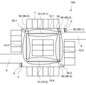
- FIG. 1 is a schematic diagram showing a ventilation system 100 according to a first embodiment, the ventilation system 100 being installed in a parking lot.
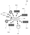
- FIG. 2 is a schematic diagram showing signal communication connections in the ventilation system 100.
- 2 is a block diagram showing the functional configuration of a control unit 30 of the ventilation system 100.
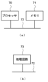
- FIG. 2 is a block diagram showing the hardware configuration of a control unit 30 of the ventilation system 100.
- FIG. 4 is a flowchart showing the operation of a control unit 30 of the ventilation system 100.
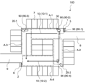
- FIG. 1 is a schematic diagram showing a plurality of areas set up in a parking lot in which a ventilation system 100 is installed. 6 is a flowchart showing the operation of step S4 shown in FIG. 5.
- FIG. 5 is a schematic diagram showing a ventilation system 100 according to a first embodiment, the ventilation system 100 being installed in a parking lot.
- FIG. 2 is a schematic diagram showing signal communication connections in the ventilation system 100.
- 2 is a block diagram showing the functional configuration of a control unit
- FIG. 11 is a schematic diagram showing a ventilation system 110 according to a second embodiment, the ventilation system 110 being installed in a parking lot.
- FIG. 9 is a schematic diagram showing the airflow system generated by the ventilation system 110 of FIG. 8 .
- FIG. 13 is a schematic diagram showing another example of the arrangement of the ventilation system 110 in a parking lot.
- FIG. 11 is another schematic diagram showing the airflow system generated by the ventilation system 110 of FIG.
- FIG. 11 is a schematic diagram showing a ventilation system 120 according to a third embodiment, the ventilation system 120 being installed in a parking lot.
- FIG. 11 is a schematic diagram showing a ventilation system 130 according to a fourth embodiment, the ventilation system 130 being installed in a parking lot.
- FIG. 13 is a block diagram showing a configuration of a learning device 200 according to a fourth embodiment. 4 is a flowchart showing the operation of the learning device 200.
- a block diagram showing a configuration of an inference device 300 according to embodiment 4. 4 is a flowchart showing the operation of the inference device 300 and the operation of the ventilation system 130.
- FIG. 1 is a schematic diagram showing a ventilation system 100 according to a first embodiment of the present disclosure.
- the ventilation system 100 is installed in an airtight parking lot, such as an underground parking lot or an indoor parking lot, and ventilates the parking lot to expel exhaust gases from the parking lot.
- the ventilation system 100 includes an intake air blower 5, an exhaust air blower 6, and a plurality of conveying air blowers 90.
- the parking lot has a substantially rectangular planar shape, and the intake air port 1 and the exhaust air port 2 are disposed at diagonal positions of the parking lot.
- the intake air port 1 and the intake air blower 5 are disposed near the entrance 8, and the intake air blower 5 supplies outside air from the intake air port 1 into the parking lot.
- the exhaust air port 2 and the exhaust air blower 6 are disposed at a corner near the exit 9, and the exhaust air blower 6 exhausts the air in the parking lot to the outside from the exhaust air port 2.
- the plurality of conveying air blowers 90 are installed in the parking lot, and convey air from the intake air blower 5 to the exhaust air blower 6 to promote ventilation in the parking lot.
- the figure illustrates a parking lot with parking spaces 7 for 26 vehicles, and a vehicle movement path 10 that branches into two near the entrance 8 and meets near the exit 9.
- vehicle movement path 10-1 One of the two vehicle movement paths 10 is called vehicle movement path 10-1, and the other is called vehicle movement path 10-2.
- conveying fans 90-1 and 90-3 are installed along vehicle movement path 10-1
- conveying fans 90-2 and 90-4 are installed along vehicle movement path 10-2.
- Conveying fans 90-1 and 90-2 are installed close to each other, and conveying fans 90-3 and 90-4 are placed diagonally across from each other in the parking lot.
- the conveying blowers 90-1 and 90-3 generate air currents 12-1 and 12-3, respectively.
- the conveying blower 90-1 is installed upwind of the conveying blower 90-3, which is disposed in a position where the air current 12-1 reaches.
- the conveying blowers 90-1 and 90-3 form an air current that flows from the air supply port 1 to the exhaust port 2 via the vehicle movement path 10-1.
- the conveying blowers 90-2 and 90-4 generate air currents 12-2 and 12-4, respectively.
- the conveying blower 90-2 is installed upwind of the conveying blower 90-4, which is disposed in a position where the air current 12-2 reaches.
- the conveying blowers 90-2 and 90-4 form an air current that flows from the air supply port 1 to the exhaust port 2 via the vehicle movement path 10-2.
- the conveying blower 90 refers to each of the conveying blowers 90-1 to 90-4.
- the ventilation system 100 includes an imaging unit 20.
- the imaging unit 20 is installed in a parking lot, and captures images of the interior of the parking lot and outputs the image data.
- the imaging unit 20 is positioned so that it can capture images of at least the vehicle movement paths 10-1 and 10-2.
- the imaging unit 20 has two cameras 20-1 and 20-2.
- the cameras 20-1 and 20-2 are installed near the transport blowers 90-3 and 90-4, respectively, and are positioned diagonally across from each other in the parking lot.
- the cameras 20-1 and 20-2 output image data of images captured in the directions they are each facing.
- the ventilation system 100 includes a control unit 30. There are no restrictions on the installation location, but the control unit 30 is installed, for example, adjacent to the conveying blower 90-2.
- Figure 2 is a schematic diagram showing the signal communication connection in the ventilation system 100.
- the control unit 30 is connected to each of the supply air blower 5, exhaust air blower 6, conveying blowers 90-1 to 90-4, camera 20-1, and camera 20-2 by wire or wirelessly. In order to simplify the wiring installation, it is desirable that each of the control unit 30, supply air blower 5, exhaust air blower 6, conveying blowers 90-1 to 90-4, camera 20-1, and camera 20-2 is wirelessly connected to the network 140. Since the control unit 30 is adjacent to the conveying blower 90-2, it may be connected to the conveying blower 90-2 by wire. The control unit 30 may be provided inside the conveying blower 90-2.
- the control unit 30 controls the operation of the intake air blower 5, exhaust air blower 6, and conveyance air blower 90.
- the control unit 30 detects the movement of the vehicle based on the image data output from the imaging unit 20, and changes the air volume of at least one of the conveyance air blowers 90-1 to 90-4.
- the air volume of a blower is the amount of airflow generated by the blower.
- FIG. 3 is a block diagram showing the functional configuration of the control unit 30.
- the control unit 30 includes a vehicle movement detection unit 31, a vehicle shape detection unit 32, and a blower control unit 33.
- the vehicle movement detection unit 31 detects the movement of a vehicle based on image data received from the imaging unit 20.
- the vehicle movement detection unit 31 also detects the position of a moving vehicle, and outputs vehicle position information indicating the position of the vehicle.
- the vehicle shape detection unit 32 detects the shape of a moving vehicle based on image data received from the imaging unit 20.
- the vehicle shape detection unit 32 outputs vehicle shape information indicating the size of the vehicle.
- the blower control unit 33 identifies at least one of the conveying blowers 90-1 to 90-4 based on the vehicle position information output from the vehicle movement detection unit 31.
- the blower control unit 33 also determines the air volume of the identified conveying blower based on the vehicle shape information.
- the blower control unit 33 sends an air volume control command to the identified conveyance blower.
- the air volume control command includes air volume information that specifies the air volume determined based on the vehicle shape information.
- the conveyance blower that receives the air volume control command changes the air volume to the specified volume based on the air volume information and operates.
- the blower has a motor and a fan, and generates an airflow by rotating the fan with the motor.
- the air volume of the blower changes by changing the operating parameters of the blower (motor rotation speed, power or power frequency supplied to the motor, etc.). Therefore, the air volume information is information for setting the operating parameters of the blower.
- the air volume information may be information that specifies an operating mode indicating one of the multiple settable stages.
- the air volume information may be information that indicates the difference between the air volume before the change and the air volume after the change.
- FIG. 4 is a block diagram showing the hardware configuration of the control unit 30.
- the control unit 30 is composed of a processor 70, a memory 71, and a bus 72.
- the processor 70 performs processing according to a program, and realizes the functions of the vehicle movement detection unit 31, the vehicle shape detection unit 32, and the blower control unit 33.
- the program is stored in the memory 71 and is provided to the processor 70 via the bus 72.
- the processor 70 is, for example, a central processing unit (CPU), and the memory 71 is a storage device including a volatile memory such as a RAM (Random Access Memory), and a non-volatile memory such as a ROM (Read Only Memory) or a flash memory.
- RAM Random Access Memory
- ROM Read Only Memory
- Image data from the imaging unit 20 is received by an interface circuit (not shown) and stored in memory 71 via bus 72.
- the processor 70 reads the image data from memory 71 and processes it.
- the air volume control command generated by the processor 70 is sent via bus 72 to another interface circuit (not shown) and then to the transport control unit.
- the configuration having a processor 70 and memory 71 as shown in FIG. 4(a) is realized by a microcomputer or the like that can also be used to control other electrical or electronic devices. However, this is not limited to this, and the control unit 30 can also be realized by a dedicated processing circuit 73 as shown in FIG. 4(b).
- the control unit 30 increases the air volume of one or more transport blowers when it detects vehicle movement from the image data.
- Figure 5 is a flow chart showing the operation of the control unit 30 for performing this control.
- the start is the point in time when operation of the ventilation system 100 begins after installation in the parking lot, and the control unit 30 issues instructions to the supply air blower 5, exhaust air blower 6, and transport blower 90 to each blow air at a specified air volume.
- the transport blower 90 is controlled to operate at the minimum air volume within the range of settable air volumes, for example.
- step S1 the vehicle movement detection unit 31 and the vehicle shape detection unit 32 each acquire image data from the imaging unit 20, i.e., from both cameras 20-1 to 20-2.
- step S2 the vehicle movement detection unit 31 detects the movement of the vehicle by detecting a change in the position of the vehicle in the moving image based on the image data. If there is no moving vehicle in the image data (No), the operation flow returns to step S1. If there is a moving vehicle (Yes), in step S3, the vehicle movement detection unit 31 detects the position of the moving vehicle.
- FIG. 6 is a schematic diagram showing multiple areas set in the parking lot shown in FIG. 1.
- Four areas A-1 to A-4 are set on the vehicle movement path 10.
- Areas A-1 and A-3 are set on the vehicle movement path 10-1, and area A-1 is located upwind of area A-3 in the air currents generated by the conveying fans 90-1 and 90-3.
- Areas A-1 and A-3 correspond to the conveying fans 90-1 and 90-3, respectively.
- Areas A-2 and A-4 are set on the vehicle movement path 10-2, and area A-2 is located upwind of area A-4 in the air currents generated by the conveying fans 90-2 and 90-4.
- Areas A-2 and A-4 correspond to the conveying fans 90-2 and 90-4, respectively.
- the vehicle movement detection unit 31 detects from the image data which of areas A-1 to A-4 the vehicle is moving through. Vehicle movement in areas A-1 and A-3 is determined from image data from camera 20-1, and vehicle movement in areas A-2 and A-4 is determined from image data from camera 20-2.
- the vehicle movement detection unit 31 generates vehicle position information indicating the area through which the vehicle is moving as the vehicle's position. The detection of the vehicle movement and the area through which the vehicle is moving from the image data is performed using known image recognition technology.
- the image data may be a moving image with a frame rate low enough that the movement of the vehicle can be detected.
- step S4 the blower control unit 33 identifies the conveying blower among the conveying blowers 90-1 to 90-4 for which the air volume should be increased based on the vehicle position information output from the vehicle movement detection unit 31.
- FIG. 7 is a flow chart showing the operation of step S4 in more detail.
- the blower control unit 33 determines whether or not a vehicle is present in area A-1. If a vehicle is present in area A-1, exhaust gas is likely to accumulate in area A-1, so it is necessary to increase the air volume in area A-1. In order to promote exhaust outside the parking lot, it is desirable to increase the air volume not only in area A-1 but also in area A-3 downstream of area A-1. Therefore, if it is determined that a vehicle is present in area A-1 (Yes), in step S4-2, the blower control unit 33 identifies the transport blowers 90-1 and 90-3. Step S4-2 is performed regardless of whether or not another vehicle is present in area A-3. The operation flow then proceeds to step S4-5.
- step S4-3 the blower control unit 33 determines whether or not a vehicle is present in area A-3. If it is determined that a vehicle is present (Yes), then in step S4-4 the blower control unit 33 identifies the conveying blower 90-3. At this time, since there is no need to increase the air volume in area A-1, the conveying blower 90-1 is not identified. The operation flow then proceeds to step S4-5. Also, if it is determined in step S4-3 that no vehicle is present (No), the operation flow proceeds to step S4-5.
- step S4-5 the blower control unit 33 determines whether or not a vehicle is present in area A-2. If a vehicle is present in area A-2, exhaust gases are likely to accumulate in area A-2, so it is necessary to increase the air volume in area A-2. In order to promote exhaust outside the parking lot, it is desirable to increase the air volume not only in area A-2 but also in area A-4, which is downstream from area A-2. Therefore, if it is determined that a vehicle is present in area A-2 (Yes), in step S4-6, the blower control unit 33 identifies the transport blowers 90-2 and 90-4. Step S4-6 is performed regardless of whether or not another vehicle is present in area A-4. The operational flow then moves to step S5.
- step S4-7 the blower control unit 33 determines whether or not a vehicle is present in area A-4. If it is determined that a vehicle is present (Yes), then in step S4-8 the blower control unit 33 identifies the conveying blower 90-4. At this time, since there is no need to increase the air volume in area A-2, the conveying blower 90-2 is not identified. The operation flow then proceeds to step S5. Also, if it is determined in step S4-7 that no vehicle is present (No), the operation flow proceeds to step S5.
- the vehicle shape detection unit 32 determines the size of each of all vehicles present in areas A-1 to A-4.
- the vehicle shape detection unit 32 detects the shape of the vehicle using existing image recognition technology and determines the size of the vehicle from the shape.
- the blower control unit 33 receives information regarding the size of the vehicle from the vehicle shape detection unit 32 and determines the air volume of the conveying blower identified in step S4 according to the size of the vehicle.
- the determined air volume is greater than the air volume of the conveying blowers 90-1 to 90-4 at the start of operation of the ventilation system 100. Since the larger the vehicle, the greater the amount of exhaust gas it emits, it is desirable to increase the air volume of the conveying blower for larger vehicles.
- the blower control unit 33 is set with multiple thresholds related to the size of the vehicle, and the blower control unit 33 determines the air volume so that the air volume is increased each time the determined vehicle size exceeds the threshold.
- step S7 the blower control unit 33 sends an air volume control command to the conveying blower identified in step S4, and controls the conveying blower to change the air volume to the one determined in step S6.
- the conveying blower that receives the air volume control command changes the air volume based on the air volume control command. If the vehicle is in area A-1, conveying blowers 90-1 and 90-3 receive the air volume control command. If the vehicle is in area A-2, conveying blowers 90-2 and 90-4 receive the air volume control command. If the vehicle is in area A-3, conveying blower 90-3 receives the air volume control command. If the vehicle is in area A-4, conveying blower 90-4 receives the air volume control command. In either case, the conveying blower that receives the air volume control command increases the air volume.
- the blower control unit 33 may control the air volume of the transport blower corresponding to that area so that the air volume is the largest of the air volumes determined for the multiple vehicles. Alternatively, the blower control unit 33 may control the air volume of the transport blower so that the air volume is increased from the largest air volume according to the number of vehicles.
- step S8 the blower control unit 33 determines whether a predetermined time has passed since the air volume of the conveying blower was changed in step S7. After the air volume is changed, the conveying blower continues to operate at the air volume changed in step S7 until the predetermined time has passed (No). When the predetermined time has passed after the air volume is changed (Yes), in step S9, the blower control unit 33 controls the air volume of the conveying blower so as to return it to the air volume before the change, i.e., the air volume at the start of operation of the ventilation system 100. The conveying blower receives an air volume control command from the blower control unit 33 and returns the air volume to the original volume based on the air volume control command. Then, the operation flow returns to step S1, and the control unit 30 repeats the operations of steps S1 to S9. Note that each of steps S1 to S9 can be rephrased as an operation performed by the control unit 30.
- the control unit 30 detects the movement of the vehicle based on image data and changes the air volume of at least one conveying blower. By using image data, the control unit 30 can quickly detect that the vehicle is generating exhaust gas, and can quickly discharge the exhaust gas.
- the control unit 30 detects the position of a moving vehicle from image data, identifies at least one of the multiple conveying blowers 90-1 to 90-4 according to the detected position, and increases the air volume of the identified conveying blower. In areas where exhaust gas is not generated in large amounts, it is not necessary to increase the air volume of the conveying blower. In other words, excessive ventilation can be prevented, thereby saving electricity usage. This leads to a reduction in the running costs of the ventilation system 100.
- the control unit 30 identifies the conveying blower that generates an airflow at the detected position of the vehicle as the conveying blower that increases the air volume, so it can quickly identify the location in the parking lot where exhaust gas needs to be exhausted.
- the control unit 30 also identifies the conveying blower located further downstream as a conveying blower that increases the air volume, so it can efficiently guide the exhaust gas outside the parking lot.
- controlling the air volume of the conveying blower based on image data also contributes to reducing the initial cost of the ventilation system 100.
- step S2 the vehicle movement detection unit 31 detects a change in the position of the vehicle in the moving image, but the movement of the vehicle may be detected by detecting the position of the vehicle. If a vehicle is present in areas A-1 to A-4 set on the vehicle movement route 10, the vehicle can be considered to be moving on the vehicle movement route 10. Therefore, in step S2, the vehicle movement detection unit 31 judges whether the vehicle is present in any of areas A-1 to A-4 from the image data. If it is determined that the vehicle is present in any of areas A-1 to A-4, the vehicle movement detection unit 31 is deemed to have detected the movement of the vehicle. Then, in step S3, the vehicle movement detection unit 31 generates vehicle position information indicating the area in which the vehicle is present (any of areas A-1 to A-4).
- the image data for detecting the movement of the vehicle at this time may be a still image.
- Step S4 is performed by the blower control unit 33, but may also be performed by the vehicle movement detection unit 31.
- the blower control unit 33 receives information identifying the conveying blower from the vehicle movement detection unit 31, and transmits an air volume control command to the identified conveying blower.
- step S6 is performed by the blower control unit 33, but may also be performed by the vehicle shape detection unit 32.
- the blower control unit 33 includes the air volume determined by the vehicle movement detection unit 31 in the air volume control command as air volume information.
- Variation (3) The control unit 30 does not necessarily require the vehicle shape detection unit 32.
- the blower control unit 33 can also control the conveying blower to increase the air volume by a predetermined amount, regardless of the size of the vehicle. This can reduce the processing burden on the control unit 30.
- Variation (4) The number and installation locations of the transport blowers are changed according to the size of the parking lot. In some parking lots, a single transport blower may be installed. In that case, when the control unit 30 detects vehicle movement, step S4 for identifying the transport blower is not necessary, and it is sufficient to increase the air volume of the only transport blower.
- the number of cameras is also changed according to the size of the parking lot. If the size of the parking lot is small, a single camera may be used as the imaging unit 20.
- Embodiment 2. 8 is a schematic diagram of a ventilation system 110 according to embodiment 2.
- the ventilation system 110 includes an intake air blower 5, an exhaust air blower 6, conveyance blowers 90-1 to 90-4, cameras 20-1 and 20-2, and a control unit 30.
- the difference from embodiment 1 is the method of identifying the conveyance blowers in the control unit 30, and the other configurations and operations are the same as those of embodiment 1.
- the control unit 30 has a parking lot map of the parking lot in which the ventilation system 110 is installed.
- the parking lot map is stored in advance in memory within the control unit 30.
- two-dimensional coordinates are set on the plane of the parking lot, and the positions of the conveying blowers 90-1 to 90-4, the cameras 20-1 and 20-2, and the exhaust port 2 are stored in advance in the control unit 30 in the form of two-dimensional coordinates.
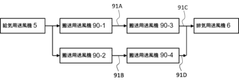
- the air supplied from the intake fan 5 is roughly divided into two systems: an airflow from the conveying fan 90-1 to the exhaust fan 6 via the conveying fan 90-3, and an airflow from the conveying fan 90-2 to the exhaust fan 6 via the conveying fan 90-4.
- the straight line connecting conveying blower 90-1 and conveying blower 90-3 is defined as air path 91A, and corresponds to conveying blower 90-1.
- Air path 91A is set by the coordinates of two points, conveying blower 90-1 and conveying blower 90-3.
- the straight line connecting conveying blower 90-3 and exhaust port 2 is defined as air path 91C, and corresponds to conveying blower 90-3.
- Air path 91C is set by the coordinates of two points, conveying blower 90-3 and exhaust port 2.
- the straight line connecting conveying blower 90-2 and conveying blower 90-4 is defined as air path 91B, and corresponds to conveying blower 90-2.
- Air path 91B is set by the coordinates of two points, conveying blower 90-2 and conveying blower 90-4.
- the straight line connecting the conveying blower 90-4 and the exhaust port 2 is defined as the air passage 91D, which corresponds to the conveying blower 90-4.
- the air passage 91D is set by the coordinates of two points, the conveying blower 90-4 and the exhaust port 2.
- the parking lot map also contains information indicating the direction of the airflow in the air passages 91A to 91D. Therefore, the control unit 30 can determine from the parking lot map that the conveying blower 90-1 is located upstream of the conveying blower 90-3, and that the conveying blower 90-2 is located upstream of the conveying blower 90-4.
- the vehicle movement detection unit 31 detects the position of the vehicle 11 as two-dimensional coordinates based on image data acquired from the cameras 20-1 and 20-2.
- the vehicle movement detection unit 31 outputs this detected position of the vehicle 11 as vehicle position information. This position detection by the vehicle movement detection unit 31 corresponds to step S3 in FIG. 5.
- the shortest distance from the vehicle 11 to the air duct 91A is defined as air duct distance 92A.
- the shortest distance from the vehicle 11 to the air duct 91B is defined as air duct distance 92B.
- the shortest distance from the vehicle 11 to the air duct 91C is defined as air duct distance 92C.
- the shortest distance from the vehicle 11 to the air duct 91D is defined as air duct distance 92D.
- the blower control unit 33 calculates each of the air duct distances 92A to 92D based on the vehicle position information received from the vehicle movement detection unit 31.
- the blower control unit 33 identifies the air duct among the air ducts 91A to 91D that has the smallest air duct distance calculated by the vehicle movement detection unit 31, and identifies the conveying blower that corresponds to the identified air duct. If there is a conveying blower downstream of the conveying blower, the conveying blower is also identified. This identification of the conveying blower by the blower control unit 33 corresponds to step S4 in FIG. 5.
- FIG. 8 shows the air duct distances 92A-92D when the vehicle 11 is parked in the parking space 7.
- step S3 since step S3 is performed after step S2, the air duct distances 92A-92D are not calculated when the vehicle 11 is parked.
- step S3 may be performed before step S2. That is, the vehicle movement detection unit 31 detects the position of the vehicle 11 and calculates the air duct distances 92A-92D, and then detects the movement of the vehicle 11.
- the blower control unit 33 identifies the transport blower based on the air duct distances 92A-92D for the vehicle 11.
- the operation of the ventilation system 110 from this point on is the same as step S5 in the first embodiment, and therefore will not be described.
- the ventilation system 110 is characterized in that multiple air paths are set for the airflow generated by the conveying blowers 90-1 to 90-4, and the control unit 30 identifies the conveying blower corresponding to the air path closest to the vehicle as the one for which the air volume should be increased.
- the control unit 30 may detect the movement of the vehicle based on the vehicle's position. For example, if the vehicle is not present in any of the parking spaces 7, it can be assumed that the vehicle is moving on the vehicle movement path 10. Therefore, it is assumed that the parking lot map contains information on the areas of all the parking spaces 7.
- the vehicle movement detection unit 31 detects the position of the vehicle regardless of the movement of the vehicle, and generates vehicle position information as two-dimensional coordinates. Then, the vehicle movement detection unit 31 judges whether the detected vehicle position is included in a parking space 7. If it is judged that the vehicle is included in any of the parking spaces 7, the vehicle movement detection unit 31 returns the operation to step S1 as the vehicle is not moving. If it is judged that the vehicle position is not included in any of the parking spaces 7, the vehicle movement detection unit 31 advances the operation to step S4 as the vehicle 11 is a moving vehicle. The detection of the movement of the vehicle is performed in step S3, and step S2 is unnecessary.
- the ventilation system 110 is not limited to the case where the air intake 1 and the exhaust 2 are arranged diagonally as shown in FIG. 8.
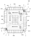
- the ventilation system 110 may be arranged at two adjacent corners among the four corners of the planar shape of the parking lot, for example, as shown in FIG. 10, the air intake 1 is arranged at the upper corner on the left side and the exhaust 2 is arranged at the lower corner on the left side.
- the conveying blower 90-1 is installed near the conveying blower 90-3 and blows air toward the conveying blower 90-2. Therefore, as shown in FIG.
- the air supplied from the air intake blower 5 is roughly divided into two systems: an airflow from the conveying blower 90-3 toward the exhaust blower 6, and an airflow from the conveying blower 90-1 toward the exhaust blower 6 via the conveying blowers 90-2 and 90-4.
- Variation (3) Each of variations (2) to (4) of embodiment 1 also applies to the ventilation system 110 of embodiment 2.
- Embodiment 3. 12 is a schematic diagram of a ventilation system 120 according to embodiment 3.
- the ventilation system 120 includes an intake air blower 5, an exhaust air blower 6, conveyance blowers 90-1 to 90-4, cameras 20-1 and 20-2, and a control unit 30.
- the difference from embodiment 1 is the method of identifying the conveyance blowers in the control unit 30, and the other configurations and operations are the same as those of embodiment 1.
- the locations of the intake air blower 5, exhaust air blower 6, transport air blowers 90-1 to 90-4, cameras 20-1, 20-2 and control unit 30 are the same as in Figure 8.
- the upper right corner is referred to as corner A, the upper left corner as corner B, the lower right corner as corner C and the lower left corner as corner D.
- the intake air port 1 and intake air blower 5 are located near corner A.
- the transport air blowers 90-1 and 90-2 are located in the passage near corner A.
- the transport air blower 90-1 blows air towards corner B.
- the transport air blower 90-2 blows air towards corner C.
- the transport air blower 90-3 is located in the passage near corner B and blows air towards corner D.
- the transport air blower 90-3 is located in the passage near corner C and blows air towards corner D.
- the exhaust port 2 and exhaust fan 6 are located near the corner D.
- Camera 20-1 is placed near corner B, and camera 20-2 is placed near corner C. Therefore, the left side of the image captured by camera 20-1 becomes the right side of the image captured by camera 20-2, and the right side of the image captured by camera 20-1 becomes the left side of the image captured by camera 20-2. Cameras 20-1 and 20-2 have the same resolution.
- the straight line 94A connecting camera 20-1 and camera 20-2 is an imaginary line added for convenience.
- straight line 94B which passes through the midpoint between camera 20-1 and camera 20-2, is parallel to the floor of the parking lot and is perpendicular to straight line 94A, and is also an imaginary line added for convenience.
- the area tangent to straight lines 94A and 94B, and the area on the left side of straight line 94B as seen from camera 20-1, is referred to as area 93A.
- the area tangent to straight lines 94A and 94B, and the area on the right side of straight line 94B as seen from camera 20-1 is referred to as area 93C.
- area 93B The area tangent to straight lines 94A and 94B, and the area on the right side of straight line 94B as seen from camera 20-2, is referred to as area 93B.
- area 93D The area tangent to lines 94A and 94B, and on the left side of line 94B as viewed from camera 20-2, is referred to as area 93D.
- areas 93A to 93D are shown in the figure as being away from lines 94A and 94B, but as described above, they are areas tangent to lines 94A and 94B.
- the vehicle movement detection unit 31 detects the position of the vehicle in one of areas 93A to 93D.
- the vehicle movement detection unit 31 detects the position of the vehicle in the image captured by one of the cameras 20-1 and 20-2.
- the position of the vehicle in the image is detected as left/right information indicating whether the vehicle is in the right or left half of the image.
- the other camera is camera 20-2, for example. If the vehicle is in the right half of the image captured by camera 20-2, it is clear that the vehicle is in one of areas 93A and 93B to the right of straight line 94A. If the vehicle is in the left half of the image captured by camera 20-2, it is clear that the vehicle is in one of areas 93C and 93D to the left of straight line 94A.
- a vehicle in the image captured by camera 20-2 is also captured by the other camera, 20-1.
- the vehicle movement detection unit 31 compares the sizes of the vehicles captured by cameras 20-1 and 20-2. If the vehicle captured by camera 20-1 is larger, it is clear that the vehicle is on the side of straight line 94A closer to camera 20-1. On the other hand, if the vehicle captured by camera 20-2 is larger, it is clear that the vehicle is on the side of straight line 94A closer to camera 20-2.
- the vehicle movement detection unit 31 detects that the vehicle captured by camera 20-2 is on the right side of straight line 94A and that camera 20-1 captures the image larger than camera 20-2, it detects that the vehicle is in area 93A.
- the vehicle movement detection unit 31 detects that the vehicle captured by camera 20-2 is on the left side of straight line 94A and that camera 20-1 captures the image larger than camera 20-2, it detects that the vehicle is in area 93C.
- the vehicle movement detection unit 31 detects that the vehicle captured by camera 20-2 is on the right side of straight line 94A and that camera 20-2 captures the image larger than camera 20-1, it detects that the vehicle is in area 93B.
- the vehicle movement detection unit 31 detects that the vehicle captured by camera 20-2 is on the left side of straight line 94A and that camera 20-2 captures the image larger than camera 20-1, it detects that the vehicle is in area 93D.
- the vehicle movement detection unit 31 outputs the detected area as vehicle position information. This detection of the area by the vehicle movement detection unit 31 corresponds to step S3 in FIG. 5.
- step S4 the blower control unit 33 identifies the conveying blower for which the air volume should be increased based on the vehicle position information output from the vehicle movement detection unit 31. If the vehicle position information indicates area 93A, the blower control unit 33 identifies the conveying blower 90-1 that generates an airflow in area 93A and the conveying blower 90-3 downstream of that. If the vehicle position information indicates area 93C, the blower control unit 33 identifies the conveying blower 90-3 that generates an airflow in area 93C. If the vehicle position information indicates area 93B, the blower control unit 33 identifies the conveying blower 90-2 that generates an airflow in area 93B and the conveying blower 90-4 downstream of that.
- the blower control unit 33 identifies the conveying blower 90-4 that generates an airflow in area 93D. This identification of the conveying blowers by the blower control unit 33 corresponds to step S4 in FIG. 5.
- the operation of the ventilation system 120 from this point onwards is the same as step S5 in embodiment 1, so its explanation will be omitted.
- the ventilation system 120 is characterized by comparing the size of the vehicle captured by the two cameras 20-1 and 20-2, and identifying the vehicle as a transport fan that should have its air volume increased based on the results of the comparison.
- Embodiment 4 A learning device 200 and an inference device 300 according to the fourth embodiment will be described. Both the learning device 200 and the inference device 300 are devices for learning and inference related to a ventilation system having a conveying blower.
- the learning device 200 acquires learning data, determines a control method for the conveying blower from the learning data by machine learning, and generates a trained model.
- the inference device 300 infers control information for controlling the conveying blower from the input data based on the trained model.
- Parking lots come in a variety of shapes, and the layout of the parking spaces 7 within each parking lot also varies, so in order to achieve efficient ventilation, it is more desirable to control the transport fan using a control method suited to each parking lot, rather than using a uniform control method to control the transport fan for multiple parking lots.
- the learning device 200 is used.
- FIG. 13 is a schematic diagram showing a ventilation system 130 related to learning by the learning device 200.
- the ventilation system 130 further includes an environmental sensor 40 in addition to the ventilation system 100 of embodiment 1.
- the environmental sensor 40 is installed on pillars or the like in the parking lot, and measures the concentration of pollutants in the air. In order to grasp the air quality throughout the parking lot, multiple environmental sensors 40 are installed in different locations in the parking lot, including the center and peripheral areas. The concentration of pollutants measured by the environmental sensor 40 is used for learning by the learning device 200.
- each environmental sensor 40 measures the CO concentration and NOX concentration as the concentration of pollutants.
- CO is slightly lighter than air and moves upwards toward the ceiling over time.
- NOX is heavier than air and moves downwards toward the floor over time.
- concentration around the mouth and nose when a person is standing is the most problematic, so it is desirable to install each environmental sensor 40 1 to 2 m above the floor of the parking lot.
- each environmental sensor 40 is expensive, and it is not practical to install them permanently in a parking lot.
- multiple environmental sensors 40 are loaned for a fixed period of time, and the learning device 220 performs learning during the loan period. When the learning period ends, the multiple environmental sensors 40 are collected and loaned to ventilation systems installed in other parking lots to be used for learning. Using the environmental sensors 40 in multiple parking lots in turn to perform learning in this way is advantageous in terms of initial costs.
- the learning device 200 and the inference device 300 will be described below in terms of a learning phase and an application phase. ⁇ Learning Phase>
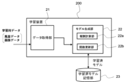
- FIG. 14 is a block diagram showing the configuration of the learning device 200.
- the learning device 200 includes a data acquisition unit 21 and a model generation unit 22.
- the data acquisition unit 21 acquires learning data from the ventilation system 130.
- the learning data includes air volume data indicating the air volume of each of the conveying fans 90-1 to 90-4 and image data of an image captured inside the parking lot.
- the image data is data of images captured by cameras 20-1 and 20-2, respectively.
- the air volume data is data indicating the air volume of each conveying blower, and is specifically expressed as data indicating the operating parameters or operating mode of each conveying blower that determines the air volume.
- the air volume data for a conveying blower whose air volume has been changed by control unit 30 based on the image data is changed to data indicating the changed air volume.
- the learning data acquired by data acquisition unit 21 is output to inference unit 42.
- the model generation unit 22 learns the air volume control command for controlling the air volume of the transport fan based on the learning data. In other words, the model generation unit 22 generates a learned model that infers optimal air volume control information from the learning data acquired from the ventilation system 110.
- the learning device 200 is connected to the ventilation system 130.
- the learning device 200 is preferably connected to, for example, a network 140 (see FIG. 2) and acquires learning data via the network 140.
- the learning device 200 may exist on a cloud server.
- the learning device 200 may be built into the ventilation system 130.
- the learning algorithm used by the model generation unit 22 can be a publicly known algorithm such as supervised learning, unsupervised learning, or reinforcement learning.
- reinforcement learning an agent (acting subject) in a certain environment observes the current state (environmental parameters) and decides on an action to be taken. The environment changes dynamically due to the agent's actions, and the agent is given a reward according to the change in the environment. The agent repeats this process and learns the action policy that will obtain the most reward through a series of actions.
- Q-learning and TD-learning are known as representative methods of reinforcement learning.
- a general update formula for the action value function Q(s, a) is expressed by Equation 1.
- st represents the state of the environment at time t, and at represents the action at time t.
- the state changes to st+1 due to action at. rt+1 represents the reward obtained due to the change in state
- ⁇ represents the discount rate
- ⁇ represents the learning coefficient.
- ⁇ is in the range of 0 ⁇ 1
- ⁇ is in the range of 0 ⁇ 1.
- the air volume of the conveying blowers 90-1 to 90-4 represents the action at
- the image captured inside the parking lot represents the state st, and the best action at for the state st at time t is learned.
- the update formula expressed by equation 1 increases the action value Q if the action value Q of the action a with the highest Q value at time t+1 is greater than the action value Q of the action a executed at time t, and decreases the action value Q in the opposite case.
- the action value function Q(s, a) is updated so that the action value Q of action a at time t approaches the best action value at time t+1.
- the best action value in a certain environment is propagated sequentially to the action value in the previous environment.
- the model generation unit 22 includes a reward calculation unit 22a and a function update unit 22b.
- the reward calculation unit 22a calculates a reward based on the learning data.
- the reward calculation unit 22a calculates a reward r based on a reward criterion.
- the reward criterion here is the CO concentration and NOX concentration measured by the multiple environmental sensors 40, and the respective concentration data is acquired by the data acquisition unit 21. For example, when the measured CO concentration and NOX concentration decrease as a result of operating the conveying blowers 90-1 to 90-4 at the air volume indicated by the air volume data, the reward calculation unit 22a increases the reward r (for example, gives a reward of "1").
- the reward calculation unit 22a reduces the reward r (for example, gives a reward of "-1").
- the function update unit 22b updates the function for determining the air volume control information for controlling the conveying fans 90-1 to 90-4 according to the reward calculated by the reward calculation unit 22a, and outputs the updated function to the learned model storage unit 23.
- the action value function Q(st,at) expressed by Equation 1 is used as the function for calculating the air volume control information.
- the learned model storage unit 23 stores the action value function Q(st,at) updated by the function update unit 122b, i.e., the learned model.
- the learned model storage unit 23 is provided outside the learning device 200, but may be a storage unit built into the learning device 200.
- FIG. 15 is a flowchart showing the operation of the learning device 200.
- step b1 the data acquisition unit 21 acquires the air volume data of the conveying blowers 90-1 to 90-4 and image data of the parking lot as learning data.
- step b2 the model generation unit 22 calculates the reward based on the learning data. Specifically, the reward calculation unit 22a acquires the learning data and determines whether to increase or decrease the reward based on the CO concentration and NOX concentration measured by the multiple environmental sensors 40, respectively.
- the remuneration calculation unit 22a determines in step b3 that the remuneration should be increased, and increases the remuneration.
- the remuneration calculation unit 22a determines in step b4 that the remuneration should be decreased, and decreases the remuneration.
- step b5 the function update unit 22b updates the action value function Q(st,at) represented by Equation 1 stored in the learned model storage unit 23 based on the reward calculated by the reward calculation unit 22a.
- the learning device 200 repeatedly executes the above steps b1 to b5, and stores the generated action value function Q(st,at) in the learned model storage unit 23 as a learned model.
- the hardware configuration of the learning device 200 is similar to that shown in FIG. 4, and includes a processor, memory, and bus 72, or includes a dedicated processing circuit.
- the learning device 200 learns based on the learning data, which includes the air volume data of the conveying fans 90-1 to 90-4 and image data of the parking lot. Through this learning, it is possible to obtain a learned model that infers air volume control information suited to the parking lot in which the ventilation system 130 is installed.
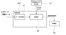
- FIG. 16 is a block diagram showing the configuration of the inference device 300.
- the inference device 300 includes a data acquisition unit 41 and an inference unit 42.
- the data acquisition unit 41 acquires input data from the ventilation system 130 after the learning period.
- the input data includes image data of an image captured inside the parking lot.
- the image data is data of images captured by the cameras 20-1 and 20-2, respectively.
- the input data acquired by the data acquisition unit 41 is output to the inference unit 42.
- the inference unit 42 reads out the learned model stored in the learned model storage unit 23 and uses this learned model to infer air volume control information. In other words, by inputting the input data acquired by the data acquisition unit 41 into this learned model, it is possible to output air volume control information suitable for the image data.
- the inference device 300 is connected to the ventilation system 130.
- the inference device 300 is connected to, for example, a network 140 (see FIG. 2) and acquires input data via the network 140.
- the inference device 300 may exist on a cloud server.
- the inference device 300 may be built into the ventilation system 130. Note that when the inference device 300 is used after the learning period, the multiple environmental sensors 40 are removed from the ventilation system 130 as described above.
- the inference device 300 has been described as inferring air volume control information using a trained model trained based on the ventilation system 130, but it may also be configured to obtain a trained model trained using another ventilation system and output air volume control information based on this trained model.
- FIG. 17 is a flowchart showing the operation of the inference device 300 and the ventilation system 100.
- step c1 the data acquisition unit 41 acquires input data.
- step c2 the inference unit 42 reads out the learned model stored in the learned model storage unit 23, and obtains air volume control information by inputting the input data acquired by the data acquisition unit 151 to this learned model.
- the air volume control information includes information identifying at least one of the conveying blowers 90-1 to 90-4 whose air volume should be changed, and information identifying the air volume after the change for each identified conveying blower.
- step c3 the inference unit 42 outputs the obtained air volume control information to the control unit 30 of the ventilation system 130.
- the control unit 30 of the ventilation system 130 controls the air volume of at least one of the identified conveyance blowers 90-1 to 90-4 based on the air volume control information obtained from the inference unit 42.
- the blower control unit 33 generates an air volume control command based on the air volume control information obtained from the inference unit 42, and sends it to the conveyance blower that should increase its air volume.
- the hardware configuration of the inference device 300 is similar to that shown in FIG. 4, and includes a processor, memory, and bus 72, or includes a dedicated processing circuit.
- the inference device 300 infers air volume control information for controlling the air volume of the transport blower based on the learned model learned by the learning device 200, and can provide the ventilation system with control of the transport blower that is suited to the parking lot in which the ventilation system 130 is installed.
- the ventilation system 130 in which the transport blower is controlled by this inferred air volume control information, can perform efficient ventilation in accordance with the movement of vehicles, improving the air quality in the parking lot.
- air volume data indicating the air volume of each of the intake air blower 5 and exhaust air blower 6 may be further added to the learning data.
- the inference device 300 further acquires air volume data indicating the air volume of each of the intake air blower 5 and exhaust air blower 6 as input data. Therefore, in the ventilation system 130 operating after the learning period, the intake air blower 5 and exhaust air blower 6 also change their air volumes to appropriate levels, providing efficient ventilation.
- the learning data of the learning device 200 may include vehicle position data indicating the position of the vehicle instead of or in addition to image data.
- the vehicle position data is vehicle position information detected from the image data by the control unit 30 (specifically, the vehicle movement detection unit 31).
- the vehicle position data is used in reinforcement learning as a parameter indicating behavior.
- supervised learning is applied to the learning algorithm used by the model generation unit 22, but this is not limited to this.
- learning algorithm in addition to supervised learning, reinforcement learning, unsupervised learning, semi-supervised learning, etc. can also be applied.
- the learning algorithm used in the model generation unit 22 can be deep learning, which learns to extract the features themselves, or machine learning can be performed according to other known methods, such as neural networks, genetic programming, functional logic programming, and support vector machines.
- the ventilation system for the study may be the ventilation system 110 of embodiment 2 with multiple environmental sensors 40 installed, or the ventilation system 110 of embodiment 3 with multiple environmental sensors 40 installed.
- Air intake 2. Exhaust, 5. Air intake fan, 6. Exhaust fan, 10, 10-1, 10-2.
- Vehicle movement path 11. Vehicle, 12-1 to 12-4. Air flow, 20. Imaging unit, 20-1, 20-2. Camera, 21, 41. Data acquisition unit, 22. Model generation unit, 30. Control unit, 31. Vehicle movement detection unit, 32. Vehicle shape detection unit, 33. Fan control unit, 40. Environmental sensor, 42. Inference unit, 90, 90-1 to 90-4. Transport fan, 91A to 91D. Air path, 100, 110, 120, 130, 140. Ventilation system, 200. Learning device, 300. Inference device
Landscapes
- Engineering & Computer Science (AREA)
- Architecture (AREA)
- Chemical & Material Sciences (AREA)
- Combustion & Propulsion (AREA)
- Mechanical Engineering (AREA)
- General Engineering & Computer Science (AREA)
- Physics & Mathematics (AREA)
- General Physics & Mathematics (AREA)
- Civil Engineering (AREA)
- Structural Engineering (AREA)
- Air-Conditioning For Vehicles (AREA)
Abstract
Description
図1は、本開示の実施の形態1に係る換気システム100を示した模式図である。換気システム100は、地下駐車場、屋内駐車場等、気密性の高い駐車場に設置され、駐車場内の換気を行って排気ガスを駐車場外に追い出す。換気システム100は、給気用送風機5、排気用送風機6及び複数の搬送用送風機90を備える。駐車場の平面形状は略長方形であり、給気口1及び排気口2は駐車場の対角の位置に配置される。給気口1及び給気用送風機5は入庫口8付近に配置され、給気用送風機5は給気口1から外部の空気を駐車場内へ供給する。排気口2及び排気用送風機6は出庫口9付近の角部に配置され、排気用送風機6は排気口2から駐車場の空気を外部に排出する。複数の搬送用送風機90は駐車場内に設置され、駐車場内の換気を促すために給気用送風機5から排気用送風機6へ空気を搬送する。
図8は、実施の形態2に係る換気システム110の模式図である。換気システム110は、給気用送風機5、排気用送風機6、搬送用送風機90-1~90-4、カメラ20-1、カメラ20-2及び制御部30を備える。実施の形態1との相違は、制御部30における搬送用送風機の特定方法であり、それ以外の構成及び動作は実施の形態1と同一とする。
図12は、実施の形態3に係る換気システム120の模式図である。換気システム120は、給気用送風機5、排気用送風機6、搬送用送風機90-1~90-4、カメラ20-1、カメラ20-2及び制御部30を備える。実施の形態1との相違は、制御部30における搬送用送風機の特定方法であり、それ以外の構成及び動作は実施の形態1と同一とする。
実施の形態4に係る学習装置200及び推論装置300について説明する。学習装置200及び推論装置300はともに、搬送用送風機を有する換気システムに関する学習及び推論の装置である。学習装置200は学習用データを取得し、その学習用データから搬送用送風機の制御方法を機械学習によって決定し、学習済モデルを生成する。推論装置300は学習済モデルに基づき、入力データから搬送用送風機を制御するための制御情報を推論する。
<学習フェーズ>

Claims (10)
- 給気口から外部の空気を駐車場へ供給する給気用送風機と、
排気口から前記駐車場の空気を外部に排出する排気用送風機と、
前記給気用送風機から前記排気用送風機へ気流を搬送する搬送用送風機と、
前記駐車場の内部を撮像して画像データを出力する撮像部と、
前記撮像部から出力される画像データに基づいて車両の移動を検出し、前記搬送用送風機の風量を変更する制御部と
を備える、ことを特徴とする換気システム。 - 前記搬送用送風機は複数台あり、
前記制御部は、前記撮像部から出力される画像データから前記車両の位置を検出し、前記検出された位置に応じて前記複数台の搬送用送風機のうちの少なくとも1台を特定し、その特定された搬送用送風機の風量を増加させる、ことを特徴とする請求項1記載の換気システム。 - 前記制御部は、前記少なくとも1台の搬送用送風機として、前記検出された位置に気流を発生させる搬送用送風機を特定する、ことを特徴とする請求項2記載の換気システム。
- 前記制御部は、前記少なくとも1台の搬送用送風機として、前記検出された位置に気流を発生させる搬送用送風機の下流に配置された搬送用送風機を含む、ことを特徴とする請求項3記載の換気システム。
- 前記複数台の搬送用送風機がそれぞれ発生する気流の複数の風路が設定されており、
前記制御部は、前記複数の風路のうち前記車両に最も近い風路に対応する搬送用送風機を前記少なくとも1台の搬送用送風機として特定する、ことを特徴とする請求項3記載の換気システム。 - 前記撮像部は第1のカメラ及び第2のカメラを含み、
前記制御部は、前記第1のカメラ及び前記第2のカメラにより撮像される前記車両の大きさを比較し、その比較結果に応じて前記少なくとも1台の搬送用送風機を特定する、ことを特徴とする請求項3記載の換気システム。 - 前記制御部は車両の大きさを検出し、その検出された大きさに応じて風量を決定し、さらに、その決定された風量に前記搬送用送風機の風量を制御する、請求項1~6記載の換気システム。
- 搬送用送風機が設置された駐車場内の画像を示す画像データ及び前記駐車場内の車両の位置を示す車両位置データの少なくともいずれか一方のデータと、前記一方のデータにおける前記搬送用送風機の風量を示す風量データを含む学習用データを取得するデータ取得部、及び、
前記学習用データを用いて、前記駐車場内の画像及び前記駐車場内の車両の位置の少なくともいずれか一方から前記搬送用送風機の風量を制御する風量制御情報を推論するための学習済モデルを生成するモデル生成部
を備える、ことを特徴とする学習装置。 - 前記データ取得部は、前記駐車場内のCOの濃度及びNOXの濃度をそれぞれ示す濃度データを取得し、
前記モデル生成部は、前記濃度データを報酬基準にして、前記風量制御指令を推論するための学習済モデルを生成する、ことを特徴とする請求項8記載の学習装置。 - 搬送用送風機が設置された駐車場内の画像を示す画像データ及び前記駐車場内の車両の位置を示す車両位置データの少なくともいずれか一方のデータを取得するデータ取得部、及び、
前記駐車場内の画像及び前記駐車場内の車両の位置の少なくともいずれか一方から前記搬送用送風機の風量を推論するための学習済モデルを用いて、前記データ取得部で取得した前記少なくとも一方のデータから前記搬送用送風機の風量を制御するための風量制御情報を出力する推論部を備える、ことを特徴とする推論装置。
Priority Applications (1)
| Application Number | Priority Date | Filing Date | Title |
|---|---|---|---|
| JP2024576089A JPWO2024166409A1 (ja) | 2023-02-10 | 2023-06-20 |
Applications Claiming Priority (2)
| Application Number | Priority Date | Filing Date | Title |
|---|---|---|---|
| PCT/JP2023/004573 WO2024166365A1 (ja) | 2023-02-10 | 2023-02-10 | 換気システム、学習装置及び推論装置 |
| JPPCT/JP2023/004573 | 2023-02-10 |
Publications (1)
| Publication Number | Publication Date |
|---|---|
| WO2024166409A1 true WO2024166409A1 (ja) | 2024-08-15 |
Family
ID=92262256
Family Applications (2)
| Application Number | Title | Priority Date | Filing Date |
|---|---|---|---|
| PCT/JP2023/004573 Ceased WO2024166365A1 (ja) | 2023-02-10 | 2023-02-10 | 換気システム、学習装置及び推論装置 |
| PCT/JP2023/022717 Ceased WO2024166409A1 (ja) | 2023-02-10 | 2023-06-20 | 換気システム、学習装置及び推論装置 |
Family Applications Before (1)
| Application Number | Title | Priority Date | Filing Date |
|---|---|---|---|
| PCT/JP2023/004573 Ceased WO2024166365A1 (ja) | 2023-02-10 | 2023-02-10 | 換気システム、学習装置及び推論装置 |
Country Status (2)
| Country | Link |
|---|---|
| JP (1) | JPWO2024166409A1 (ja) |
| WO (2) | WO2024166365A1 (ja) |
Citations (4)
| Publication number | Priority date | Publication date | Assignee | Title |
|---|---|---|---|---|
| JPH10281518A (ja) * | 1997-04-03 | 1998-10-23 | Nippon Flaekt Kk | 送風ユニット及び屋内駐車場の換気システム |
| JPH11213292A (ja) * | 1998-01-23 | 1999-08-06 | Fujitsu Ltd | 駐車場車両誘導方法及びシステム及び駐車場車両誘導プログラムを格納した記憶媒体 |
| KR20160071531A (ko) * | 2014-12-11 | 2016-06-22 | 세종대학교산학협력단 | 동작 감지를 이용한 유인팬 네트워크 시스템 및 그 동작 방법 |
| JP2016208408A (ja) * | 2015-04-27 | 2016-12-08 | パナソニックIpマネジメント株式会社 | 検出方法、検出装置および制御方法 |
-
2023
- 2023-02-10 WO PCT/JP2023/004573 patent/WO2024166365A1/ja not_active Ceased
- 2023-06-20 JP JP2024576089A patent/JPWO2024166409A1/ja active Pending
- 2023-06-20 WO PCT/JP2023/022717 patent/WO2024166409A1/ja not_active Ceased
Patent Citations (4)
| Publication number | Priority date | Publication date | Assignee | Title |
|---|---|---|---|---|
| JPH10281518A (ja) * | 1997-04-03 | 1998-10-23 | Nippon Flaekt Kk | 送風ユニット及び屋内駐車場の換気システム |
| JPH11213292A (ja) * | 1998-01-23 | 1999-08-06 | Fujitsu Ltd | 駐車場車両誘導方法及びシステム及び駐車場車両誘導プログラムを格納した記憶媒体 |
| KR20160071531A (ko) * | 2014-12-11 | 2016-06-22 | 세종대학교산학협력단 | 동작 감지를 이용한 유인팬 네트워크 시스템 및 그 동작 방법 |
| JP2016208408A (ja) * | 2015-04-27 | 2016-12-08 | パナソニックIpマネジメント株式会社 | 検出方法、検出装置および制御方法 |
Also Published As
| Publication number | Publication date |
|---|---|
| JPWO2024166409A1 (ja) | 2024-08-15 |
| WO2024166365A1 (ja) | 2024-08-15 |
Similar Documents
| Publication | Publication Date | Title |
|---|---|---|
| US11301779B2 (en) | Air conditioner | |
| JP6889279B2 (ja) | デジタル画像内の物体を検出するためのシステムおよび方法、ならびに物体検出を再スコアリングするためのシステムおよび方法 | |
| SE520911C2 (sv) | Rengöringsrobot, rengöringsrobotsystem och metod för att styra en rengöringsrobot | |
| CN114783047B (zh) | 基于边缘计算的室内吸烟检测方法和装置 | |
| WO2024166409A1 (ja) | 換気システム、学習装置及び推論装置 | |
| CN113793371A (zh) | 目标分割追踪方法、装置、电子设备和存储介质 | |
| US20240295338A1 (en) | Airflow control system and airflow control method | |
| CN118313993A (zh) | 一种公路特长隧道空气质量优化调控方法及系统 | |
| JP2006016951A (ja) | 地下空間の空調システム | |
| WO2023089740A1 (ja) | 換気空気調和制御システムおよび換気空気調和制御装置 | |
| CN118968455B (zh) | 一种多目标协同的智能驾驶测试场景运行调节控制方法 | |
| JPH10184298A (ja) | 集中排気式道路トンネル換気制御装置 | |
| CN116817392B (zh) | 一种地下室通风排烟方法、系统、智能终端及存储介质 | |
| JP3904506B2 (ja) | トンネル換気制御方法および装置 | |
| JP7309069B2 (ja) | 空気調和装置の制御のための学習装置および推論装置 | |
| CN112984753A (zh) | 新风系统的控制方法、新风系统及计算机可读存储介质 | |
| KR102603732B1 (ko) | 주차 인식 방법, 주차 인식 시스템 및 상기 방법을 실행시키기 위하여 기록매체에 저장된 컴퓨터 프로그램 | |
| WO2024157314A1 (ja) | 駐車場換気システム、駐車場換気方法、学習装置および推論装置 | |
| JP2025067344A (ja) | 学習装置、学習方法及び学習プログラム | |
| JP2003210934A (ja) | 排ガス処理装置 | |
| CN115568014A (zh) | 基于自适应的区域划分的分布式多跳定位方法 | |
| WO2023162150A1 (ja) | 換気制御システムおよび換気制御装置 | |
| Leonardi et al. | Synthesis of distributed execution platforms for cyber-physical systems with applications to high-performance buildings | |
| JP7699686B1 (ja) | 排気システム | |
| CN112149789A (zh) | 用于实施功能测试的方法和设备 |
Legal Events
| Date | Code | Title | Description |
|---|---|---|---|
| 121 | Ep: the epo has been informed by wipo that ep was designated in this application |
Ref document number: 23921236 Country of ref document: EP Kind code of ref document: A1 |
|
| ENP | Entry into the national phase |
Ref document number: 2024576089 Country of ref document: JP Kind code of ref document: A |
|
| WWE | Wipo information: entry into national phase |
Ref document number: 2024576089 Country of ref document: JP |
|
| NENP | Non-entry into the national phase |
Ref country code: DE |
|
| 122 | Ep: pct application non-entry in european phase |
Ref document number: 23921236 Country of ref document: EP Kind code of ref document: A1 |