WO2024166370A1 - Dispositif de commande de véhicule et procédé de commande de véhicule - Google Patents
Dispositif de commande de véhicule et procédé de commande de véhicule Download PDFInfo
- Publication number
- WO2024166370A1 WO2024166370A1 PCT/JP2023/004581 JP2023004581W WO2024166370A1 WO 2024166370 A1 WO2024166370 A1 WO 2024166370A1 JP 2023004581 W JP2023004581 W JP 2023004581W WO 2024166370 A1 WO2024166370 A1 WO 2024166370A1
- Authority
- WO
- WIPO (PCT)
- Prior art keywords
- torque
- vehicle
- control unit
- motor
- threshold value
- Prior art date
- Legal status (The legal status is an assumption and is not a legal conclusion. Google has not performed a legal analysis and makes no representation as to the accuracy of the status listed.)
- Ceased
Links
Images






Classifications
-
- B—PERFORMING OPERATIONS; TRANSPORTING
- B60—VEHICLES IN GENERAL
- B60L—PROPULSION OF ELECTRICALLY-PROPELLED VEHICLES; SUPPLYING ELECTRIC POWER FOR AUXILIARY EQUIPMENT OF ELECTRICALLY-PROPELLED VEHICLES; ELECTRODYNAMIC BRAKE SYSTEMS FOR VEHICLES IN GENERAL; MAGNETIC SUSPENSION OR LEVITATION FOR VEHICLES; MONITORING OPERATING VARIABLES OF ELECTRICALLY-PROPELLED VEHICLES; ELECTRIC SAFETY DEVICES FOR ELECTRICALLY-PROPELLED VEHICLES
- B60L15/00—Methods, circuits, or devices for controlling the traction-motor speed of electrically-propelled vehicles
- B60L15/20—Methods, circuits, or devices for controlling the traction-motor speed of electrically-propelled vehicles for control of the vehicle or its driving motor to achieve a desired performance, e.g. speed, torque, programmed variation of speed
-
- B—PERFORMING OPERATIONS; TRANSPORTING
- B60—VEHICLES IN GENERAL
- B60L—PROPULSION OF ELECTRICALLY-PROPELLED VEHICLES; SUPPLYING ELECTRIC POWER FOR AUXILIARY EQUIPMENT OF ELECTRICALLY-PROPELLED VEHICLES; ELECTRODYNAMIC BRAKE SYSTEMS FOR VEHICLES IN GENERAL; MAGNETIC SUSPENSION OR LEVITATION FOR VEHICLES; MONITORING OPERATING VARIABLES OF ELECTRICALLY-PROPELLED VEHICLES; ELECTRIC SAFETY DEVICES FOR ELECTRICALLY-PROPELLED VEHICLES
- B60L3/00—Electric devices on electrically-propelled vehicles for safety purposes; Monitoring operating variables, e.g. speed, deceleration or energy consumption
- B60L3/10—Indicating wheel slip ; Correction of wheel slip
- B60L3/106—Indicating wheel slip ; Correction of wheel slip for maintaining or recovering the adhesion of the drive wheels
-
- B—PERFORMING OPERATIONS; TRANSPORTING
- B60—VEHICLES IN GENERAL
- B60L—PROPULSION OF ELECTRICALLY-PROPELLED VEHICLES; SUPPLYING ELECTRIC POWER FOR AUXILIARY EQUIPMENT OF ELECTRICALLY-PROPELLED VEHICLES; ELECTRODYNAMIC BRAKE SYSTEMS FOR VEHICLES IN GENERAL; MAGNETIC SUSPENSION OR LEVITATION FOR VEHICLES; MONITORING OPERATING VARIABLES OF ELECTRICALLY-PROPELLED VEHICLES; ELECTRIC SAFETY DEVICES FOR ELECTRICALLY-PROPELLED VEHICLES
- B60L2240/00—Control parameters of input or output; Target parameters
- B60L2240/10—Vehicle control parameters
- B60L2240/12—Speed
-
- B—PERFORMING OPERATIONS; TRANSPORTING
- B60—VEHICLES IN GENERAL
- B60L—PROPULSION OF ELECTRICALLY-PROPELLED VEHICLES; SUPPLYING ELECTRIC POWER FOR AUXILIARY EQUIPMENT OF ELECTRICALLY-PROPELLED VEHICLES; ELECTRODYNAMIC BRAKE SYSTEMS FOR VEHICLES IN GENERAL; MAGNETIC SUSPENSION OR LEVITATION FOR VEHICLES; MONITORING OPERATING VARIABLES OF ELECTRICALLY-PROPELLED VEHICLES; ELECTRIC SAFETY DEVICES FOR ELECTRICALLY-PROPELLED VEHICLES
- B60L2240/00—Control parameters of input or output; Target parameters
- B60L2240/10—Vehicle control parameters
- B60L2240/14—Acceleration
- B60L2240/16—Acceleration longitudinal
-
- B—PERFORMING OPERATIONS; TRANSPORTING
- B60—VEHICLES IN GENERAL
- B60L—PROPULSION OF ELECTRICALLY-PROPELLED VEHICLES; SUPPLYING ELECTRIC POWER FOR AUXILIARY EQUIPMENT OF ELECTRICALLY-PROPELLED VEHICLES; ELECTRODYNAMIC BRAKE SYSTEMS FOR VEHICLES IN GENERAL; MAGNETIC SUSPENSION OR LEVITATION FOR VEHICLES; MONITORING OPERATING VARIABLES OF ELECTRICALLY-PROPELLED VEHICLES; ELECTRIC SAFETY DEVICES FOR ELECTRICALLY-PROPELLED VEHICLES
- B60L2240/00—Control parameters of input or output; Target parameters
- B60L2240/10—Vehicle control parameters
- B60L2240/14—Acceleration
- B60L2240/18—Acceleration lateral
-
- B—PERFORMING OPERATIONS; TRANSPORTING
- B60—VEHICLES IN GENERAL
- B60L—PROPULSION OF ELECTRICALLY-PROPELLED VEHICLES; SUPPLYING ELECTRIC POWER FOR AUXILIARY EQUIPMENT OF ELECTRICALLY-PROPELLED VEHICLES; ELECTRODYNAMIC BRAKE SYSTEMS FOR VEHICLES IN GENERAL; MAGNETIC SUSPENSION OR LEVITATION FOR VEHICLES; MONITORING OPERATING VARIABLES OF ELECTRICALLY-PROPELLED VEHICLES; ELECTRIC SAFETY DEVICES FOR ELECTRICALLY-PROPELLED VEHICLES
- B60L2240/00—Control parameters of input or output; Target parameters
- B60L2240/10—Vehicle control parameters
- B60L2240/14—Acceleration
- B60L2240/20—Acceleration angular
-
- B—PERFORMING OPERATIONS; TRANSPORTING
- B60—VEHICLES IN GENERAL
- B60L—PROPULSION OF ELECTRICALLY-PROPELLED VEHICLES; SUPPLYING ELECTRIC POWER FOR AUXILIARY EQUIPMENT OF ELECTRICALLY-PROPELLED VEHICLES; ELECTRODYNAMIC BRAKE SYSTEMS FOR VEHICLES IN GENERAL; MAGNETIC SUSPENSION OR LEVITATION FOR VEHICLES; MONITORING OPERATING VARIABLES OF ELECTRICALLY-PROPELLED VEHICLES; ELECTRIC SAFETY DEVICES FOR ELECTRICALLY-PROPELLED VEHICLES
- B60L2240/00—Control parameters of input or output; Target parameters
- B60L2240/10—Vehicle control parameters
- B60L2240/24—Steering angle
-
- B—PERFORMING OPERATIONS; TRANSPORTING
- B60—VEHICLES IN GENERAL
- B60L—PROPULSION OF ELECTRICALLY-PROPELLED VEHICLES; SUPPLYING ELECTRIC POWER FOR AUXILIARY EQUIPMENT OF ELECTRICALLY-PROPELLED VEHICLES; ELECTRODYNAMIC BRAKE SYSTEMS FOR VEHICLES IN GENERAL; MAGNETIC SUSPENSION OR LEVITATION FOR VEHICLES; MONITORING OPERATING VARIABLES OF ELECTRICALLY-PROPELLED VEHICLES; ELECTRIC SAFETY DEVICES FOR ELECTRICALLY-PROPELLED VEHICLES
- B60L2240/00—Control parameters of input or output; Target parameters
- B60L2240/40—Drive Train control parameters
- B60L2240/42—Drive Train control parameters related to electric machines
- B60L2240/421—Speed
-
- B—PERFORMING OPERATIONS; TRANSPORTING
- B60—VEHICLES IN GENERAL
- B60L—PROPULSION OF ELECTRICALLY-PROPELLED VEHICLES; SUPPLYING ELECTRIC POWER FOR AUXILIARY EQUIPMENT OF ELECTRICALLY-PROPELLED VEHICLES; ELECTRODYNAMIC BRAKE SYSTEMS FOR VEHICLES IN GENERAL; MAGNETIC SUSPENSION OR LEVITATION FOR VEHICLES; MONITORING OPERATING VARIABLES OF ELECTRICALLY-PROPELLED VEHICLES; ELECTRIC SAFETY DEVICES FOR ELECTRICALLY-PROPELLED VEHICLES
- B60L2240/00—Control parameters of input or output; Target parameters
- B60L2240/40—Drive Train control parameters
- B60L2240/42—Drive Train control parameters related to electric machines
- B60L2240/423—Torque
-
- B—PERFORMING OPERATIONS; TRANSPORTING
- B60—VEHICLES IN GENERAL
- B60L—PROPULSION OF ELECTRICALLY-PROPELLED VEHICLES; SUPPLYING ELECTRIC POWER FOR AUXILIARY EQUIPMENT OF ELECTRICALLY-PROPELLED VEHICLES; ELECTRODYNAMIC BRAKE SYSTEMS FOR VEHICLES IN GENERAL; MAGNETIC SUSPENSION OR LEVITATION FOR VEHICLES; MONITORING OPERATING VARIABLES OF ELECTRICALLY-PROPELLED VEHICLES; ELECTRIC SAFETY DEVICES FOR ELECTRICALLY-PROPELLED VEHICLES
- B60L2240/00—Control parameters of input or output; Target parameters
- B60L2240/40—Drive Train control parameters
- B60L2240/46—Drive Train control parameters related to wheels
- B60L2240/461—Speed
-
- B—PERFORMING OPERATIONS; TRANSPORTING
- B60—VEHICLES IN GENERAL
- B60L—PROPULSION OF ELECTRICALLY-PROPELLED VEHICLES; SUPPLYING ELECTRIC POWER FOR AUXILIARY EQUIPMENT OF ELECTRICALLY-PROPELLED VEHICLES; ELECTRODYNAMIC BRAKE SYSTEMS FOR VEHICLES IN GENERAL; MAGNETIC SUSPENSION OR LEVITATION FOR VEHICLES; MONITORING OPERATING VARIABLES OF ELECTRICALLY-PROPELLED VEHICLES; ELECTRIC SAFETY DEVICES FOR ELECTRICALLY-PROPELLED VEHICLES
- B60L2240/00—Control parameters of input or output; Target parameters
- B60L2240/40—Drive Train control parameters
- B60L2240/46—Drive Train control parameters related to wheels
- B60L2240/463—Torque
-
- B—PERFORMING OPERATIONS; TRANSPORTING
- B60—VEHICLES IN GENERAL
- B60L—PROPULSION OF ELECTRICALLY-PROPELLED VEHICLES; SUPPLYING ELECTRIC POWER FOR AUXILIARY EQUIPMENT OF ELECTRICALLY-PROPELLED VEHICLES; ELECTRODYNAMIC BRAKE SYSTEMS FOR VEHICLES IN GENERAL; MAGNETIC SUSPENSION OR LEVITATION FOR VEHICLES; MONITORING OPERATING VARIABLES OF ELECTRICALLY-PROPELLED VEHICLES; ELECTRIC SAFETY DEVICES FOR ELECTRICALLY-PROPELLED VEHICLES
- B60L2240/00—Control parameters of input or output; Target parameters
- B60L2240/60—Navigation input
- B60L2240/64—Road conditions
- B60L2240/647—Surface situation of road, e.g. type of paving
-
- B—PERFORMING OPERATIONS; TRANSPORTING
- B60—VEHICLES IN GENERAL
- B60L—PROPULSION OF ELECTRICALLY-PROPELLED VEHICLES; SUPPLYING ELECTRIC POWER FOR AUXILIARY EQUIPMENT OF ELECTRICALLY-PROPELLED VEHICLES; ELECTRODYNAMIC BRAKE SYSTEMS FOR VEHICLES IN GENERAL; MAGNETIC SUSPENSION OR LEVITATION FOR VEHICLES; MONITORING OPERATING VARIABLES OF ELECTRICALLY-PROPELLED VEHICLES; ELECTRIC SAFETY DEVICES FOR ELECTRICALLY-PROPELLED VEHICLES
- B60L2250/00—Driver interactions
- B60L2250/26—Driver interactions by pedal actuation
-
- B—PERFORMING OPERATIONS; TRANSPORTING
- B60—VEHICLES IN GENERAL
- B60L—PROPULSION OF ELECTRICALLY-PROPELLED VEHICLES; SUPPLYING ELECTRIC POWER FOR AUXILIARY EQUIPMENT OF ELECTRICALLY-PROPELLED VEHICLES; ELECTRODYNAMIC BRAKE SYSTEMS FOR VEHICLES IN GENERAL; MAGNETIC SUSPENSION OR LEVITATION FOR VEHICLES; MONITORING OPERATING VARIABLES OF ELECTRICALLY-PROPELLED VEHICLES; ELECTRIC SAFETY DEVICES FOR ELECTRICALLY-PROPELLED VEHICLES
- B60L2270/00—Problem solutions or means not otherwise provided for
- B60L2270/10—Emission reduction
- B60L2270/14—Emission reduction of noise
- B60L2270/145—Structure borne vibrations
-
- Y—GENERAL TAGGING OF NEW TECHNOLOGICAL DEVELOPMENTS; GENERAL TAGGING OF CROSS-SECTIONAL TECHNOLOGIES SPANNING OVER SEVERAL SECTIONS OF THE IPC; TECHNICAL SUBJECTS COVERED BY FORMER USPC CROSS-REFERENCE ART COLLECTIONS [XRACs] AND DIGESTS
- Y02—TECHNOLOGIES OR APPLICATIONS FOR MITIGATION OR ADAPTATION AGAINST CLIMATE CHANGE
- Y02T—CLIMATE CHANGE MITIGATION TECHNOLOGIES RELATED TO TRANSPORTATION
- Y02T10/00—Road transport of goods or passengers
- Y02T10/60—Other road transportation technologies with climate change mitigation effect
- Y02T10/72—Electric energy management in electromobility
Definitions
- This disclosure relates to a vehicle control device and a vehicle control method that are installed in a vehicle.
- Patent Documents 1 and 2 Various technologies have been proposed to operate vehicles more safely (see, for example, Patent Documents 1 and 2).
- a vehicle control device is a device that controls a vehicle that runs by being driven by a motor.
- This vehicle control device includes a control unit that is capable of deriving a target torque by adding a periodically fluctuating torque to a required torque according to an acceleration request, and controlling the torque of the motor based on the derived target torque.
- This control unit is capable of controlling the torque of the motor based on the target torque when any of the slip angle, slip ratio, and road surface utilization rate of the vehicle becomes greater than a predetermined threshold value.
- a vehicle control method is a method for controlling a vehicle that runs by motor drive. This vehicle control method includes the following two steps. (A) Deriving a target torque by adding a periodically varying torque to a torque requirement corresponding to an acceleration requirement. (B) Controlling the torque of the motor based on the derived target torque when any one of the slip angle, slip ratio, and road surface utilization rate of the vehicle becomes larger than a predetermined threshold value.
- FIG. 1 is a diagram illustrating an example of functional blocks of a vehicle including a vehicle control unit according to an embodiment of the present disclosure.
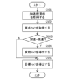
- FIG. 2 is a diagram for explaining an example of a procedure for deriving a target torque in the traveling control unit of FIG.
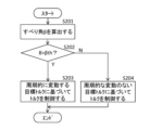
- FIG. 3 is a diagram for explaining an example of a torque control procedure in the travel control unit of FIG.
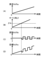
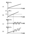
- Fig. 4(A) is a diagram showing an example of a waveform of a required torque
- Fig. 4(B) is a diagram showing an example of a waveform of a slip angle
- Fig. 4(C) is a diagram showing an example of a waveform of a fluctuating torque
- Fig. 4(D) is a diagram showing an example of a waveform of a target torque.
- FIG. 9 is a diagram showing an example of the relationship between the slip ratio and the tire longitudinal force.
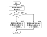
- FIG. 10 is a diagram for explaining an example of a torque control procedure in the traveling control unit of FIG. 1.
- Fig. 11(A) is a diagram showing an example of a waveform of a required torque
- Fig. 11(B) is a diagram showing an example of a waveform of a road surface utilization rate
- Fig. 11(C) is a diagram showing an example of a waveform of a fluctuating torque
- Fig. 11(D) is a diagram showing an example of a waveform of a target torque.
- FIG. 12 is a diagram showing a modified example of the functional blocks of the vehicle shown in FIG.
- the motor output is smoother than the engine output, making it difficult for the driver to detect vehicle slippage. As a result, the driver may not realize that the vehicle is possibly slipping, exposing the vehicle to danger. It is desirable to provide a vehicle control device and a vehicle control method that can make the driver aware of the possibility of vehicle slippage.
- Fig. 1 illustrates an example of a schematic configuration of a vehicle 1 including a control unit 20 according to an embodiment of the present disclosure.
- the control unit 20 corresponds to a specific example of a "control unit" in the present disclosure.
- the vehicle 1 is capable of running by being driven by a motor.
- the vehicle 1 includes a sensor unit 10, a control unit 20, and a motor 30.
- the sensor unit 10 is configured to include various sensors mounted on the vehicle 1.
- the sensor unit 10 is configured to include an accelerator opening sensor 11, a vehicle speed sensor 12, an acceleration sensor 13, an angular velocity sensor 14, a steering angle sensor 15, a steering torque sensor 16, and a road surface friction coefficient sensor 17.
- the sensor unit 10 may include sensors other than those mentioned above.
- the accelerator opening sensor 11 is capable of detecting the accelerator opening from the amount of depression of the accelerator pedal.
- the accelerator opening sensor 11 is capable of outputting time series data (accelerator opening data) regarding the detected accelerator opening to the control unit 20.
- the vehicle speed sensor 12 is capable of detecting the speed (vehicle speed) of the vehicle 1.
- the vehicle speed sensor 12 is capable of outputting time series data (vehicle speed data) on the detected vehicle speed to the control unit 20.
- the acceleration sensor 13 is capable of detecting the acceleration applied to the vehicle 1.
- the acceleration sensor 13 is capable of outputting time series data (acceleration data) on the detected acceleration in three directions to the control unit 20.
- the angular velocity sensor 14 is capable of detecting the angular velocity of the vehicle 1.
- the angular velocity sensor 14 is capable of outputting time series data (angular velocity data) on the detected three angular velocities (yaw angular velocity, roll angular velocity, pitch angular velocity) to the control unit 20.
- the steering angle sensor 15 is capable of detecting the steering angle (steering angle) of the steering wheel of the vehicle 1.
- the steering angle sensor 15 is capable of outputting time series data (steering angle data) on the detected steering angle to the control unit 20.
- the steering torque sensor 16 is capable of detecting the steering torque generated by the driver's steering wheel operation.
- the steering torque sensor 16 is capable of outputting time series data (steering torque data) on the detected steering torque to the control unit 20.
- the road surface friction coefficient sensor 17 is capable of estimating, for example, the friction coefficient of the road surface ahead of the vehicle 1.
- the road surface friction coefficient sensor 17 is configured to include, for example, a camera that captures an image ahead of the vehicle 1, a temperature sensor (outside air temperature sensor, road surface temperature sensor), a near-infrared sensor, a laser light sensor (TOF (Time of Flight) sensor), and other non-contact sensors.
- the road surface friction coefficient sensor 17 is capable of estimating the road surface friction coefficient, for example, based on the detection results of the above-mentioned non-contact sensors.
- the road surface friction coefficient sensor 17 is capable of outputting time-series data (road surface friction coefficient data) on the estimated road surface friction coefficient to the control unit 20.
- the road surface friction coefficient sensor 17 may be, for example, a road surface sensor that directly measures the road surface friction coefficient.
- the control unit 20 is capable of controlling the entire vehicle 1.
- the control unit 20 is, for example, a so-called ECU (Electronic Control Unit) and is configured to include, for example, one or more processors and one or more memories.
- the control unit 20 may be configured to include, for example, a CPU (Central Processing Unit).
- the control unit 20 is capable of controlling the entire vehicle 1, for example, by executing a program stored in a memory unit.
- the control unit 20 is capable of controlling the vehicle 1 that runs by being driven by a motor.
- the control unit 20 has a driving control unit 21, for example, as shown in FIG. 1.
- the driving control unit 21 is capable of controlling the running of the vehicle 1 (for example, the torque of the motor 30).
- the driving control unit 21 has a required torque derivation unit 22, a fluctuating torque derivation unit 23, and a motor torque control unit 24, for example, as shown in FIG. 1.
- the required torque derivation unit 22 is capable of deriving a required torque according to an acceleration request.
- the acceleration request refers to the depression of the accelerator pedal or a change in the amount of depression of the accelerator pedal.
- the acceleration request may be made by the driver during manual driving, or by the cruise control unit 21 during automatic driving.
- the required torque derivation unit 22 is capable of deriving the amount of torque (required torque) that should be generated by the motor 30 based on the accelerator opening data obtained from the accelerator opening sensor 11.
- the fluctuating torque derivation unit 23 is capable of deriving fluctuating torque that fluctuates periodically.
- the fluctuating torque is intended to make the driver aware of the possibility of vehicle 1 slipping by intentionally changing the behavior of the vehicle 1.
- the fluctuating torque derivation unit 23 may, for example, be capable of making the fluctuation range, period, and waveform of the fluctuating torque constant regardless of the magnitude of the required torque.
- the fluctuating torque derivation unit 23 may, for example, be capable of deriving fluctuating torque with a fluctuation range that is 10% of the magnitude of the required torque.
- the motor torque control unit 24 is capable of deriving a target torque by adding a fluctuating torque to the required torque, and controlling the torque of the motor 30 based on the derived target torque.
- the motor torque control unit 24 is capable of calculating the slip angle ⁇ of the vehicle 1 based on the sensor data obtained by the sensor unit 10.
- the motor torque control unit 24 is capable of controlling the torque of the motor 30 based on the target torque when the calculated slip angle ⁇ becomes larger than a predetermined threshold value.
- the motor torque control unit 24 is capable of controlling the torque of the motor 30 by using the required torque as the target torque.
- the motor torque control unit 24 is capable of outputting the target torque as a control signal to the motor 30.
- the motor 30 is configured to drive the steered wheels of the vehicle 1.
- the motor 30 is capable of driving the steered wheels of the vehicle 1 according to the target torque input from the motor torque control unit 24.
- the steered wheels refer to at least one of the front wheels and the rear wheels.
- Fig. 2 is a diagram for explaining an example of a procedure for deriving a target torque.
- the driving control unit 21 acquires an acceleration request from the accelerator opening sensor 11 (step S101). Next, when the driving control unit 21 acquires an acceleration request from the accelerator opening sensor 11 (step S102), if the acquired acceleration request is an acceleration or deceleration request (step S103; Y), it derives a fluctuating torque (step S104). If the acquired acceleration request is not an acceleration request or a deceleration request (step S103; N), or if the driving control unit 21 has derived a fluctuating torque in step S104, it derives a target torque (step S105). If the acquired acceleration request is not an acceleration request or a deceleration request, the driving control unit 21 sets the required torque according to the acceleration request as the target torque. If the driving control unit 21 has derived a fluctuating torque in step S104, it derives the target torque by adding a fluctuating torque that fluctuates periodically to the required torque according to the acceleration request.
- FIG. 3 is a diagram for explaining an example of a torque control procedure in the driving control unit 21.
- the driving control unit 21 calculates the slip angle ⁇ based on the sensor data obtained by the sensor unit 10 (step S201). Next, the driving control unit 21 determines whether the calculated slip angle ⁇ is greater than a predetermined threshold value ⁇ th (step S202). As a result, if the slip angle ⁇ is greater than the predetermined threshold value ⁇ th (step S202; Y), the driving control unit 21 controls the torque of the motor 30 based on the periodically varying target torque (step S203). On the other hand, if the slip angle ⁇ is equal to or less than the predetermined threshold value ⁇ th (step S202; N), the driving control unit 21 controls the torque of the motor 30 based on the target torque that does not periodically vary (step S204). In this manner, torque control based on the derived target torque is performed.
- a target torque is derived by adding a periodically varying fluctuating torque to the required torque according to the acceleration request, and the torque of the motor 30 is controlled based on the derived target torque.
- the torque of the motor 30 is controlled based on the target torque.
- the steering wheels of the vehicle 1 are driven according to the target torque, so that the behavior of the vehicle 1 fluctuates according to the target torque.
- Figure 4(A) shows an example of the waveform of the required torque ta.
- Figure 4(B) shows an example of the waveform of the slip angle ⁇ .
- Figure 4(C) shows an example of the waveform of the fluctuating torque tb.
- Figure 4(D) shows an example of the waveform of the target torque tc.
- the cruise control unit 21 is capable of outputting the periodically varying target torque tc to the motor 30 at a timing before the timing at which the driver feels that the vehicle 1 is not accelerating as much as expected given the amount of accelerator depression.
- the threshold value ⁇ th is set to the value of the slip angle ⁇ at a timing before the timing at which the driver feels that the vehicle 1 is not accelerating as much as expected given the amount of accelerator depression.
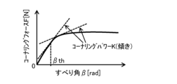
- the cornering force F is a function of the slip angle ⁇ , as shown in FIG. 5, for example.
- the tangent to this function corresponds to the cornering power K.
- the amount of change in cornering force F with respect to the slip angle ⁇ corresponds to the cornering power K.
- ⁇ F/ ⁇ the amount of change in cornering force F with respect to the slip angle ⁇
- the cornering power K is large, a small change in the slip angle ⁇ results in a large change in the cornering force F.
- the cornering power K suddenly decreases.
- the cornering power K decreases, the increase in cornering force F with respect to the change in the slip angle ⁇ decreases. This causes a phenomenon in which the vehicle 1 does not accelerate as much as the driver expected, despite the amount of depression of the accelerator.
- the slip angle ⁇ at a timing before the timing at which the driver feels that the vehicle 1 is not accelerating as expected in relation to the amount of accelerator depression is set as the threshold value ⁇ th, and when the slip angle ⁇ becomes larger than the threshold value ⁇ th, the driving control unit 21 is able to control the torque of the motor 30 based on the periodically varying target torque.
- the threshold value ⁇ th is a value larger than 0 and smaller than the slip angle ⁇ at which the cornering power K becomes a negative value. This makes it possible to make the driver aware of the possibility of the vehicle 1 slipping before the vehicle 1 is exposed to danger.
- the motor torque control unit 24 may be capable of calculating a slip ratio ⁇ instead of the slip angle ⁇ .
- the slip ratio ⁇ is calculated as (Vw-V)/Vw during acceleration, and as (V-Vw)/Vw during deceleration, where V is the vehicle speed and Vw is the wheel speed.
- the motor torque control unit 24 is capable of controlling the torque of the motor 30 based on the target torque when the calculated slip ratio ⁇ becomes greater than a predetermined threshold.
- the motor torque control unit 24 is capable of controlling the torque of the motor 30 by using the required torque as the target torque.
- the motor torque control unit 24 is capable of outputting the target torque as a control signal to the motor 30.
- FIG. 6 is a diagram for explaining an example of a torque control procedure in the driving control unit 21.
- the driving control unit 21 calculates the slip ratio ⁇ based on the sensor data obtained by the sensor unit 10 (step S301). Next, the driving control unit 21 determines whether the calculated slip ratio ⁇ is greater than a predetermined threshold ⁇ th (step S302). As a result, if the slip ratio ⁇ is greater than the predetermined threshold ⁇ th (step S302; Y), the driving control unit 21 controls the torque of the motor 30 based on the periodically fluctuating target torque (step S303). On the other hand, if the slip ratio ⁇ is equal to or less than the predetermined threshold ⁇ th (step S302; N), the driving control unit 21 controls the torque of the motor 30 based on the target torque that does not vary periodically (step S304). In this manner, torque control based on the derived target torque is performed.
- a target torque is derived by adding a periodically varying fluctuating torque to the required torque according to the acceleration request, and the torque of the motor 30 is controlled based on the derived target torque.
- the torque of the motor 30 is controlled based on the target torque.
- the steering wheels of the vehicle 1 are driven according to the target torque, so that the behavior of the vehicle 1 fluctuates according to the target torque.
- Figure 7(A) shows an example of the waveform of the required torque ta.
- Figure 7(B) shows an example of the waveform of the slip ratio ⁇ .
- Figure 7(C) shows an example of the waveform of the fluctuating torque tb.
- Figure 7(D) shows an example of the waveform of the target torque tc.
- the cornering force F stops increasing with an increase in the slip ratio ⁇ , and the cornering power K decreases. This means that it becomes gradually more difficult for the vehicle 1 to turn as the slip ratio ⁇ increases.
- the tire longitudinal force stops increasing with an increase in the slip ratio ⁇ . This means that it becomes gradually more difficult for the vehicle 1 to accelerate as the slip ratio ⁇ increases.
- the driver realizes that it is gradually becoming more difficult for the vehicle 1 to turn or to accelerate, the vehicle 1 may be exposed to danger.
- the cornering force F is a function of the slip ratio ⁇ , as shown in Figure 8, for example.
- the tangent to this function corresponds to the cornering power K.
- the amount of change in cornering force F with respect to the slip ratio ⁇ corresponds to the cornering power K.
- the cornering power K is large, a small change in the slip ratio ⁇ results in a large change in the cornering force F.
- the cornering power K suddenly decreases.
- the cornering power K decreases, the increase in cornering force F with respect to the change in the slip ratio ⁇ decreases. This causes a phenomenon in which the vehicle 1 does not accelerate as much as the driver expected, despite the amount of depression of the accelerator.
- the slip ratio ⁇ at a timing before the timing at which the driver feels that the vehicle 1 is not turning as much as expected given the amount of steering wheel rotation is set as a threshold value ⁇ th1, and when the slip ratio ⁇ becomes larger than the threshold value ⁇ th1, the driving control unit 21 is able to control the torque of the motor 30 based on the periodically varying target torque. This makes it possible to make the driver aware of the possibility of vehicle 1 slipping before the vehicle 1 is exposed to danger.
- the slip ratio ⁇ at a timing before the timing at which the driver feels that the vehicle 1 is not accelerating as much as expected in relation to the amount of accelerator depression is set as a threshold value ⁇ th2, and when the slip ratio ⁇ becomes larger than the threshold value ⁇ th2, the driving control unit 21 is able to control the torque of the motor 30 based on the periodically varying target torque. This makes it possible to make the driver aware of the possibility of vehicle 1 slipping before the vehicle 1 is exposed to danger.
- the motor torque control unit 24 may be capable of calculating a road surface utilization rate R instead of the slip angle ⁇ .
- the road surface utilization rate R is calculated by the following formula (1).
- Fx is the tire longitudinal force [N], and is calculated, for example, by inputting the sensor data obtained from the sensor unit 10 into a magic formula or the like.
- Fy is the tire longitudinal force (cornering force) [N], and is calculated, for example, by inputting the sensor data obtained from the sensor unit 10 into a magic formula or the like.
- Fz is the tire ground contact load [N], and is obtained, for example, by a vehicle model.
- the motor torque control unit 24 is capable of controlling the torque of the motor 30 based on the target torque when the calculated road surface utilization rate R is greater than a predetermined threshold. When the calculated road surface utilization rate R is equal to or less than a predetermined threshold, the motor torque control unit 24 is capable of controlling the torque of the motor 30 by using the required torque as the target torque. The motor torque control unit 24 is capable of outputting the target torque as a control signal to the motor 30.
- FIG. 10 is a diagram for explaining an example of a torque control procedure in the driving control unit 21.
- the driving control unit 21 calculates the road surface utilization rate R based on the sensor data obtained by the sensor unit 10 (step S401). Next, the driving control unit 21 determines whether the calculated road surface utilization rate R is greater than a predetermined threshold value Rth (step S402). As a result, if the road surface utilization rate R is greater than the predetermined threshold value Rth (step S402; Y), the driving control unit 21 controls the torque of the motor 30 based on the periodically fluctuating target torque (step S403). On the other hand, if the road surface utilization rate R is equal to or less than the predetermined threshold value Rth (step S402; N), the driving control unit 21 controls the torque of the motor 30 based on the target torque that does not vary periodically (step S404). In this manner, torque control based on the derived target torque is performed.
- a target torque is derived by adding a periodically varying fluctuating torque to the required torque according to the acceleration request, and the torque of the motor 30 is controlled based on the derived target torque.
- the torque of the motor 30 is controlled based on the target torque.
- the steering wheels of the vehicle 1 are driven according to the target torque, so that the behavior of the vehicle 1 fluctuates according to the target torque.
- FIG. 11(A) shows an example of the waveform of the required torque ta.
- FIG. 11(B) shows an example of the waveform of the road surface utilization rate R.
- FIG. 11(C) shows an example of the waveform of the fluctuating torque tb.
- FIG. 11(D) shows an example of the waveform of the target torque tc.
- a target torque tc having a waveform in which a fluctuating torque tb is added to the required torque ta is generated (Figs. 11(C) and 11(D)).
- the cruise control unit 21 outputs the target torque tc having a waveform as shown in Fig. 11(D) to the motor 30.
- the motor 30 drives the steered wheels of the vehicle 1 according to the target torque tc input from the cruise control unit 21.
- the behavior of the vehicle 1 fluctuates according to the target torque tc.
- the cornering force F increases.
- the rate of increase in the cornering force F relative to the road surface utilization rate R becomes gentler. This means that as the road surface utilization rate R increases, the tires begin to slip. When such tire slip occurs, the driver feels that the vehicle 1 is not accelerating as much as expected given how much the accelerator is depressed. However, once the driver recognizes the tire slip, the vehicle 1 may be exposed to danger.
- the driving control unit 21 is able to output the periodically varying target torque tc to the motor 30 at a timing before the driver feels that the vehicle 1 is not accelerating as much as expected given the amount of accelerator depression.
- the threshold value Rth is set to the value of the road surface utilization rate R at a timing before the driver feels that the vehicle 1 is not accelerating as much as expected given the amount of accelerator depression.
- the cornering power K is set to a threshold value Rth where the road surface utilization rate R is an arbitrary value greater than 0 and less than 1, and when the road surface utilization rate R becomes greater than the threshold value Rth, the driving control unit 21 is able to control the torque of the motor 30 based on the periodically varying target torque.
- the vehicle 1 may further include, for example, an input I/F 40 that accepts input from a user such as a driver, and a memory unit 50 that stores the input accepted by the input I/F 40, as shown in FIG. 12 .
- the input I/F 40 is composed of input devices such as a keyboard, mouse, and touch panel.
- the memory unit 50 is composed of, for example, a RAM (Random Access Memory), a ROM (Read Only Memory), and an auxiliary storage device (such as a hard disk).
- the input I/F 40 accepts input of a threshold value 51 from a user such as a driver, and outputs the accepted threshold value 51 to the driving control unit 21.
- the driving control unit 21 stores the threshold value 51 acquired from a user such as a driver via the input I/F 40 in the memory unit 50.
- the threshold value 51 is stored in the memory unit 50.
- the threshold value 51 is, for example, a threshold value ⁇ th, a threshold value ⁇ th, a threshold value ⁇ th1, a threshold value ⁇ th2, or a threshold value Rth.
- the driving control unit 21 may be configured to control the torque of the motor 30 based on the periodically varying target torque when the calculated slip angle ⁇ is greater than the threshold value ⁇ th read from the storage unit 50 (step S203).
- the driving control unit 21 may be configured to control the torque of the motor 30 based on the target torque that does not periodically vary when the calculated slip angle ⁇ is equal to or less than the threshold value ⁇ th read from the storage unit 50 (step S204).
- the driving control unit 21 may control the torque of the motor 30 based on the target torque that varies periodically when the calculated slip ratio ⁇ is greater than the threshold value (threshold ⁇ th, threshold ⁇ th1, or threshold ⁇ th2) read from the storage unit 50 (step S303).
- the driving control unit 21 may control the torque of the motor 30 based on the target torque that does not vary periodically when the calculated slip ratio ⁇ is equal to or less than the threshold value (threshold ⁇ th, threshold ⁇ th1, or threshold ⁇ th2) read from the storage unit 50 (step S204).
- the driving control unit 21 may be configured to control the torque of the motor 30 based on the periodically varying target torque when the calculated road surface utilization rate R is greater than the threshold value Rth read from the storage unit 50 (step S403).
- the driving control unit 21 may be configured to control the torque of the motor 30 based on the target torque that does not periodically vary when the calculated road surface utilization rate R is equal to or less than the threshold value Rth read from the storage unit 50 (step S404).
- the presence or absence of periodic fluctuations in torque is set based on a threshold value input by a user such as a driver. This makes it possible to make a user such as a driver aware of the possibility of vehicle 1 slipping before vehicle 1 is exposed to danger.
- the driving control unit 21 may be configured to set whether or not there is a periodic fluctuation in torque based on a threshold value set in accordance with the driving characteristics of the driver, for example.
- the driving control unit 21 may be configured to control the torque of the motor 30 based on the periodically varying target torque when the calculated slip angle ⁇ is greater than a threshold value ⁇ th set according to the driving characteristics of the driver (step S203).
- the driving control unit 21 may be configured to control the torque of the motor 30 based on the target torque that does not periodically vary when the calculated slip angle ⁇ is equal to or less than a threshold value ⁇ th set according to the driving characteristics of the driver (step S204).
- the driving control unit 21 may control the torque of the motor 30 based on the target torque that varies periodically when the calculated slip ratio ⁇ is greater than a threshold value (threshold ⁇ th, threshold ⁇ th1, or threshold ⁇ th2) set according to the driving characteristics of the driver (step S303).
- the driving control unit 21 may control the torque of the motor 30 based on the target torque that does not vary periodically when the calculated slip ratio ⁇ is equal to or less than a threshold value (threshold ⁇ th, threshold ⁇ th1, or threshold ⁇ th2) set according to the driving characteristics of the driver (step S204).
- the driving control unit 21 may be configured to control the torque of the motor 30 based on a periodically varying target torque when the calculated road surface utilization rate R is greater than a threshold value Rth set according to the driving characteristics of the driver (step S403).
- the driving control unit 21 may be configured to control the torque of the motor 30 based on a target torque that does not periodically vary when the calculated road surface utilization rate R is equal to or less than a threshold value Rth set according to the driving characteristics of the driver (step S404).
- the presence or absence of periodic fluctuations in torque is set based on a threshold value set according to the driving characteristics of the driver. This makes it possible to make the driver aware of the possibility of vehicle 1 slipping before vehicle 1 is exposed to danger.
- a vehicle control device for controlling a vehicle driven by a motor a control unit capable of deriving a target torque by adding a periodically varying torque fluctuation to a torque requirement corresponding to an acceleration requirement, and controlling a torque of a motor based on the derived target torque;
- the control unit is capable of controlling the torque of the motor based on the target torque when any one of a slip angle, a slip ratio, and a road surface utilization rate of the vehicle becomes larger than a predetermined threshold value.
- the threshold value is a threshold value input by a driver.
- the threshold value is set in accordance with a driving characteristic of a driver.
- the threshold value is a slip angle that is greater than 0 and smaller than a slip angle at which the cornering power becomes a negative value.
- the threshold value is a road surface utilization rate that is greater than 0 and less than 1.
- a vehicle control method for controlling a vehicle driven by a motor comprising: Deriving a target torque by adding a periodically varying fluctuating torque to a required torque according to an acceleration request; and controlling a torque of a motor based on the derived target torque when any one of a slip angle, a slip ratio, and a road surface utilization ratio of the vehicle becomes larger than a predetermined threshold value.
- the control unit 20 shown in FIG. 1 can be implemented by a circuit including at least one semiconductor integrated circuit, such as at least one processor (e.g., a central processing unit (CPU)), at least one application specific integrated circuit (ASIC) and/or at least one field programmable gate array (FPGA).
- the at least one processor can be configured to perform all or a portion of the various functions of the control unit 20 shown in FIG. 1 by reading instructions from at least one non-transitory and tangible computer-readable medium.
- Such media can take various forms, including, but not limited to, various magnetic media such as hard disks, various optical media such as CDs or DVDs, various semiconductor memories such as volatile or non-volatile memories (i.e., semiconductor circuits). Volatile memories can include DRAM and SRAM.
- Non-volatile memories can include ROM and NVRAM.
- An ASIC is an integrated circuit (IC) specialized to perform all or a portion of the various functions of the control unit 20 shown in FIG. 1.
- An FPGA is an integrated circuit that is designed to be configurable after manufacture to perform all or part of the various functions of the control unit 20 shown in FIG. 1.
Landscapes
- Engineering & Computer Science (AREA)
- Power Engineering (AREA)
- Transportation (AREA)
- Mechanical Engineering (AREA)
- Life Sciences & Earth Sciences (AREA)
- Sustainable Development (AREA)
- Sustainable Energy (AREA)
- Electric Propulsion And Braking For Vehicles (AREA)
Abstract
Priority Applications (4)
| Application Number | Priority Date | Filing Date | Title |
|---|---|---|---|
| CN202380014334.1A CN118786050A (zh) | 2023-02-10 | 2023-02-10 | 车辆控制装置及车辆控制方法 |
| DE112023005770.2T DE112023005770T5 (de) | 2023-02-10 | 2023-02-10 | Fahrzeugsteuerungsvorrichtung und fahrzeugsteuerungsverfahren |
| PCT/JP2023/004581 WO2024166370A1 (fr) | 2023-02-10 | 2023-02-10 | Dispositif de commande de véhicule et procédé de commande de véhicule |
| JP2024576056A JPWO2024166370A1 (fr) | 2023-02-10 | 2023-02-10 |
Applications Claiming Priority (1)
| Application Number | Priority Date | Filing Date | Title |
|---|---|---|---|
| PCT/JP2023/004581 WO2024166370A1 (fr) | 2023-02-10 | 2023-02-10 | Dispositif de commande de véhicule et procédé de commande de véhicule |
Publications (1)
| Publication Number | Publication Date |
|---|---|
| WO2024166370A1 true WO2024166370A1 (fr) | 2024-08-15 |
Family
ID=92262702
Family Applications (1)
| Application Number | Title | Priority Date | Filing Date |
|---|---|---|---|
| PCT/JP2023/004581 Ceased WO2024166370A1 (fr) | 2023-02-10 | 2023-02-10 | Dispositif de commande de véhicule et procédé de commande de véhicule |
Country Status (4)
| Country | Link |
|---|---|
| JP (1) | JPWO2024166370A1 (fr) |
| CN (1) | CN118786050A (fr) |
| DE (1) | DE112023005770T5 (fr) |
| WO (1) | WO2024166370A1 (fr) |
Citations (5)
| Publication number | Priority date | Publication date | Assignee | Title |
|---|---|---|---|---|
| JP2007112367A (ja) * | 2005-10-24 | 2007-05-10 | Hitachi Ltd | 車両タイヤ状態検出方法および車両タイヤ状態検出装置 |
| US20120293313A1 (en) * | 2011-05-20 | 2012-11-22 | Ford Global Technologies, Llc | Method and Apparatus for Generating Vehicle Vibration to Alert Vehicle User of Warning |
| JP2015198567A (ja) * | 2014-04-03 | 2015-11-09 | 株式会社ジェイテクト | 車両用制御装置 |
| JP2016005339A (ja) * | 2014-06-16 | 2016-01-12 | 三菱自動車工業株式会社 | 電動車両の走行制御装置 |
| JP2020075597A (ja) * | 2018-11-07 | 2020-05-21 | 本田技研工業株式会社 | 車両挙動安定化装置 |
-
2023
- 2023-02-10 DE DE112023005770.2T patent/DE112023005770T5/de active Pending
- 2023-02-10 CN CN202380014334.1A patent/CN118786050A/zh active Pending
- 2023-02-10 JP JP2024576056A patent/JPWO2024166370A1/ja active Pending
- 2023-02-10 WO PCT/JP2023/004581 patent/WO2024166370A1/fr not_active Ceased
Patent Citations (5)
| Publication number | Priority date | Publication date | Assignee | Title |
|---|---|---|---|---|
| JP2007112367A (ja) * | 2005-10-24 | 2007-05-10 | Hitachi Ltd | 車両タイヤ状態検出方法および車両タイヤ状態検出装置 |
| US20120293313A1 (en) * | 2011-05-20 | 2012-11-22 | Ford Global Technologies, Llc | Method and Apparatus for Generating Vehicle Vibration to Alert Vehicle User of Warning |
| JP2015198567A (ja) * | 2014-04-03 | 2015-11-09 | 株式会社ジェイテクト | 車両用制御装置 |
| JP2016005339A (ja) * | 2014-06-16 | 2016-01-12 | 三菱自動車工業株式会社 | 電動車両の走行制御装置 |
| JP2020075597A (ja) * | 2018-11-07 | 2020-05-21 | 本田技研工業株式会社 | 車両挙動安定化装置 |
Also Published As
| Publication number | Publication date |
|---|---|
| DE112023005770T5 (de) | 2025-11-27 |
| JPWO2024166370A1 (fr) | 2024-08-15 |
| CN118786050A (zh) | 2024-10-15 |
Similar Documents
| Publication | Publication Date | Title |
|---|---|---|
| US8781686B2 (en) | Device/method for controlling turning behavior of vehicle | |
| JP4045961B2 (ja) | 制動制御装置 | |
| JP6162762B2 (ja) | 車両の制御装置及び車両の制御方法 | |
| US7440823B2 (en) | Intention estimation method and system with confidence indication | |
| JP6626523B2 (ja) | 車両の制御装置及び車両の制御方法 | |
| CN110001645B (zh) | 车辆的驱动力控制装置 | |
| CN110239499B (zh) | 车辆的控制装置及车辆的控制方法 | |
| JP2009096349A (ja) | 車両用運転支援装置 | |
| JP5211995B2 (ja) | 車両用減速制御装置及びその方法 | |
| US10407034B2 (en) | Combined slip-based driver command interpreter | |
| CN110371102A (zh) | 用于控制车辆的车道变换的装置和方法 | |
| US11845458B2 (en) | Vehicle drive force control method and vehicle drive force control device | |
| US12110072B2 (en) | Steering control device | |
| JP2015023691A (ja) | 車両の駆動制御装置 | |
| JP6674769B2 (ja) | 車両の制御装置及び車両の制御方法 | |
| US10970945B2 (en) | Control apparatus for vehicle and control method for vehicle | |
| US7643926B2 (en) | Rolling motion stability control apparatus for a vehicle | |
| WO2023212001A1 (fr) | Procédé et système d'estimation de coefficient de frottement chaussee/pneu | |
| CN118786050A (zh) | 车辆控制装置及车辆控制方法 | |
| CN118849801A (zh) | 制动控制装置及制动控制方法 | |
| JP4928221B2 (ja) | 車両挙動制御装置 | |
| CN115871620A (zh) | 车辆控制装置 | |
| JP6245076B2 (ja) | 車両用加速度センサの出力補正装置 | |
| WO2024166369A1 (fr) | Dispositif de commande de véhicule et procédé de commande de véhicule | |
| US20260021706A1 (en) | Vehicle control apparatus |
Legal Events
| Date | Code | Title | Description |
|---|---|---|---|
| WWE | Wipo information: entry into national phase |
Ref document number: 202380014334.1 Country of ref document: CN |
|
| WWE | Wipo information: entry into national phase |
Ref document number: 18723787 Country of ref document: US |
|
| 121 | Ep: the epo has been informed by wipo that ep was designated in this application |
Ref document number: 23921199 Country of ref document: EP Kind code of ref document: A1 |
|
| ENP | Entry into the national phase |
Ref document number: 2024576056 Country of ref document: JP Kind code of ref document: A |
|
| WWE | Wipo information: entry into national phase |
Ref document number: 2024576056 Country of ref document: JP |
|
| WWE | Wipo information: entry into national phase |
Ref document number: 112023005770 Country of ref document: DE |
|
| 122 | Ep: pct application non-entry in european phase |
Ref document number: 23921199 Country of ref document: EP Kind code of ref document: A1 |