WO2024166318A1 - Système d'imagerie, procédé d'imagerie et programme d'imagerie - Google Patents
Système d'imagerie, procédé d'imagerie et programme d'imagerie Download PDFInfo
- Publication number
- WO2024166318A1 WO2024166318A1 PCT/JP2023/004425 JP2023004425W WO2024166318A1 WO 2024166318 A1 WO2024166318 A1 WO 2024166318A1 JP 2023004425 W JP2023004425 W JP 2023004425W WO 2024166318 A1 WO2024166318 A1 WO 2024166318A1
- Authority
- WO
- WIPO (PCT)
- Prior art keywords
- camera
- drone
- area
- photographing
- unit
- Prior art date
- Legal status (The legal status is an assumption and is not a legal conclusion. Google has not performed a legal analysis and makes no representation as to the accuracy of the status listed.)
- Ceased
Links
Images


Classifications
-
- B—PERFORMING OPERATIONS; TRANSPORTING
- B64—AIRCRAFT; AVIATION; COSMONAUTICS
- B64U—UNMANNED AERIAL VEHICLES [UAV]; EQUIPMENT THEREFOR
- B64U10/00—Type of UAV
- B64U10/10—Rotorcrafts
- B64U10/13—Flying platforms
- B64U10/14—Flying platforms with four distinct rotor axes, e.g. quadcopters
-
- B—PERFORMING OPERATIONS; TRANSPORTING
- B64—AIRCRAFT; AVIATION; COSMONAUTICS
- B64U—UNMANNED AERIAL VEHICLES [UAV]; EQUIPMENT THEREFOR
- B64U20/00—Constructional aspects of UAVs
- B64U20/80—Arrangement of on-board electronics, e.g. avionics systems or wiring
- B64U20/87—Mounting of imaging devices, e.g. mounting of gimbals
-
- H—ELECTRICITY
- H04—ELECTRIC COMMUNICATION TECHNIQUE
- H04N—PICTORIAL COMMUNICATION, e.g. TELEVISION
- H04N23/00—Cameras or camera modules comprising electronic image sensors; Control thereof
- H04N23/60—Control of cameras or camera modules
- H04N23/66—Remote control of cameras or camera parts, e.g. by remote control devices
-
- H—ELECTRICITY
- H04—ELECTRIC COMMUNICATION TECHNIQUE
- H04N—PICTORIAL COMMUNICATION, e.g. TELEVISION
- H04N23/00—Cameras or camera modules comprising electronic image sensors; Control thereof
- H04N23/60—Control of cameras or camera modules
- H04N23/69—Control of means for changing angle of the field of view, e.g. optical zoom objectives or electronic zooming
-
- H—ELECTRICITY
- H04—ELECTRIC COMMUNICATION TECHNIQUE
- H04N—PICTORIAL COMMUNICATION, e.g. TELEVISION
- H04N23/00—Cameras or camera modules comprising electronic image sensors; Control thereof
- H04N23/60—Control of cameras or camera modules
- H04N23/695—Control of camera direction for changing a field of view, e.g. pan, tilt or based on tracking of objects
-
- H—ELECTRICITY
- H04—ELECTRIC COMMUNICATION TECHNIQUE
- H04N—PICTORIAL COMMUNICATION, e.g. TELEVISION
- H04N23/00—Cameras or camera modules comprising electronic image sensors; Control thereof
- H04N23/90—Arrangement of cameras or camera modules, e.g. multiple cameras in TV studios or sports stadiums
-
- H—ELECTRICITY
- H04—ELECTRIC COMMUNICATION TECHNIQUE
- H04N—PICTORIAL COMMUNICATION, e.g. TELEVISION
- H04N5/00—Details of television systems
- H04N5/222—Studio circuitry; Studio devices; Studio equipment
-
- B—PERFORMING OPERATIONS; TRANSPORTING
- B64—AIRCRAFT; AVIATION; COSMONAUTICS
- B64U—UNMANNED AERIAL VEHICLES [UAV]; EQUIPMENT THEREFOR
- B64U2101/00—UAVs specially adapted for particular uses or applications
- B64U2101/30—UAVs specially adapted for particular uses or applications for imaging, photography or videography
Definitions
- the present invention relates to a photography system, a photography method, and a photography program.
- Patent document 1 discloses a technology for simultaneously flying multiple drones to photograph an object.
- Patent Document 1 had blind spots, or areas of the playing area that could not be photographed, and was therefore unable to capture all of the events occurring on the field being photographed.
- the present invention was made in consideration of the above problems, and aims to provide a photography system that can capture all events that occur in the field being photographed.
- a photography system comprises a plurality of moving objects that move within a predetermined moving area, a first camera and a second camera that are mounted on each of the plurality of moving objects and capture at least a portion of a field to be photographed, and a camera control command unit that controls the second camera based on the photographing area photographed by the first camera so that the second camera photographs a blind spot area not photographed by the first camera.
- the camera control command unit may control at least one of the position, direction, and zoom amount of the second camera.
- the system may further include a blind spot area determination unit that determines, based on the area captured by the first camera, at least one of an area outside the field of view of the first camera and a shadow area within the field of view as the blind spot area, and the camera control command unit may control the second camera to capture the blind spot area with the second camera.
- a blind spot area determination unit that determines, based on the area captured by the first camera, at least one of an area outside the field of view of the first camera and a shadow area within the field of view as the blind spot area
- the camera control command unit may control the second camera to capture the blind spot area with the second camera.
- the system may further include a photographing area determination unit that determines the photographing area of the first camera based on an image photographed by the first camera.
- the system may further include a target area determination unit that determines a target area, which is an area to be photographed in the photographing field, and the blind spot area determination unit may determine the blind spot area based on the position or photographing direction of the first camera and the target area.
- the blind spot area determination unit may predict the blind spot area from the current time onwards, and the camera control command unit may control the second camera based on the predicted blind spot area.
- the system may further include a display control unit that displays at least one of the shooting area and the blind spot area on the operation screen.
- the first camera and the second camera may be mounted on a drone or a device placed on the ground, or may be fixed to a wire and be movable by pulling up or down the wire.
- the camera control command unit may control the other cameras, including the second camera, to capture the blind spot area.
- the camera control command unit may control the second camera to capture an overhead image of a range wider than the image capture area of the first camera when the first camera is tracking and capturing an image of a specific object.
- the first camera and the second camera are mounted on a first drone and a second drone, respectively, and the field to be photographed is a predefined rectangular court surrounded by a pair of touchlines and a pair of goal lines, and the camera control command unit may fly the first drone and the second drone along a pair of touchlines on both sides of the field to be photographed, or a pair of goal lines, or the touchlines and the goal lines, to photograph by complementing each other's blind spot areas.
- the first camera and the second camera are mounted on a first drone and a second drone, respectively, and the field to be photographed has a rectangular court surrounded by a pair of touchlines and a pair of goal lines, and a halfway line connecting the midpoints of the pair of touchlines defined in advance, and the camera control command unit may fly the first drone and the second drone facing each other to photograph a first area and a second area within the court divided by the halfway line, thereby complementing each other's blind spot areas and photographing them.
- the camera may further include a subject position estimation unit that estimates the position of a subject to be photographed, and when the subject to be photographed moves outside the photographing area of the first camera, the subject position estimation unit estimates the position of the subject to be photographed based on an image captured by the second camera, and the camera control command unit may control the first camera so that the subject to be photographed is included in the photographing area of the first camera.
- a subject position estimation unit that estimates the position of a subject to be photographed, and when the subject to be photographed moves outside the photographing area of the first camera, the subject position estimation unit estimates the position of the subject to be photographed based on an image captured by the second camera, and the camera control command unit may control the first camera so that the subject to be photographed is included in the photographing area of the first camera.
- the camera may further include a subject position estimation unit that estimates the position of a subject to be photographed, and when the subject to be photographed moves outside the photographing area of the first camera, the subject position estimation unit estimates the position of the subject to be photographed based on a past image captured by the first camera or the second camera, and the camera control command unit may control at least one of the first camera and the second camera so that the subject to be photographed is included in the photographing area of the first camera or the second camera.
- a subject position estimation unit that estimates the position of a subject to be photographed, and when the subject to be photographed moves outside the photographing area of the first camera, the subject position estimation unit estimates the position of the subject to be photographed based on a past image captured by the first camera or the second camera, and the camera control command unit may control at least one of the first camera and the second camera so that the subject to be photographed is included in the photographing area of the first camera or the second camera.
- the first camera may be mounted on a first drone, and the camera control command unit may move a third drone equipped with a third camera to the position of the first drone when the remaining battery charge of the first drone falls below a predetermined value, or when an abnormality or malfunction of the first drone or the first camera is detected, and may cause the first drone to retreat when the third drone photographs the same area as the photographing area of the first drone.
- a photographing method is a system having a plurality of moving objects moving in a predetermined moving area, and a first camera and a second camera mounted on each of the plurality of moving objects and photographing at least a part of a field to be photographed, the system executing a camera control command step for controlling the second camera to photograph a blind spot area not photographed by the first camera based on the photographing area photographed by the first camera.
- a photography program causes a system having a plurality of moving objects moving within a predetermined moving area, and a first camera and a second camera mounted on each of the plurality of moving objects and photographing at least a portion of a field to be photographed, to execute a camera control command step for controlling the second camera to photograph a blind spot area not photographed by the first camera based on the photographing area photographed by the first camera.
- computer programs can be provided by being stored on various data-readable recording media, or by being made available for download via a network such as the Internet.
- the present invention makes it possible to capture the entire competition.
- FIG. 1 is a diagram showing the overall configuration of an imaging system according to an embodiment of the present invention
- FIG. 2 is a simplified external perspective view of the drone according to the embodiment.
- FIG. 2 is a functional configuration diagram of the drone according to the embodiment.
- FIG. 2 is a simplified external perspective view of the mobile camera according to the embodiment.
- FIG. 2 is a functional configuration diagram of the mobile camera according to the embodiment.
- FIG. 2 is a simplified external perspective view of the fixed camera according to the embodiment.
- FIG. 2 is a functional configuration diagram of the fixed camera according to the embodiment.
- (a) is a simplified front view of the exterior of the control device of the embodiment;
- (b) is a schematic diagram showing the direction in which the drone moves or turns in response to input from the control device.
- FIG. 2 is a functional configuration diagram of the control device according to the embodiment.
- FIG. 2 is a functional configuration diagram of a server according to the embodiment.
- FIG. 2 is a schematic diagram showing a stadium, which is an example of a field to be photographed.
- FIG. 4 is a diagram showing an example of a screen displayed on a terminal of the imaging system.
- 13 is an example of a table showing a correspondence relationship between identification numbers of target areas in the photographing field and three-dimensional coordinates.
- 3 is a schematic diagram showing a target area, a shooting area, and a blind spot area in the shooting field.
- FIG. 1 is a schematic diagram showing a first example of how the subject field is photographed by multiple drones.
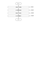
- FIG. 1 is a flowchart of a control executed during flight of the drone.
- 13A, 13B, and 13C are schematic diagrams showing a fourth example, a fifth example, and a sixth example, of the manner in which the subject field is photographed by multiple drones.
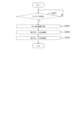
- 13 is a flowchart showing an example of a process when a long path is detected.
- An example of an image of a long pass captured by a first drone (b) A schematic diagram showing how the field to be photographed is photographed by multiple drones at the time the long pass is captured; (c) A schematic diagram showing the appearance of the photography area of the second drone, which has been changed in response to the detection of the long pass.
- Schematic diagrams showing a first example of how the shooting area of a first drone is changed when the ball deviates from the shooting area of the first drone including: (a) an example of an image captured of the ball deviating from the shooting area of the first drone; (b) a schematic diagram showing how the field to be photographed is photographed by multiple drones at the time when the ball's deviation is photographed; (c) an example of an image captured by the second drone at the time when the ball's deviation is photographed; and (d) a schematic diagram showing the appearance of the first drone's shooting area changed in response to the detection of the ball's deviation.
- Schematic diagrams showing a second example of how the shooting area of a first drone is changed when the ball deviates from the shooting area of the first drone (a) an example of a captured image showing the ball deviating from the shooting area of the first drone; (b) a schematic diagram showing the field to be photographed by multiple drones at the time when the ball's deviation is captured; (c) an example of an image captured by the second drone at the time when the ball's deviation is captured; and (d) a schematic diagram showing the first drone's shooting area changed in response to the detection of the ball's deviation.
- 13 is a flowchart illustrating an example of a process for changing drones within the subject field.
- Schematic diagrams showing the state when drones are switched within the field to be photographed including (a) a schematic diagram showing the state in which the field to be photographed is photographed by multiple drones, (b) an example of an image photographed by a first drone, (c) an example of an image photographed by a second drone, and (d) an example of an image photographed by a third drone.
- 1 is a schematic diagram showing a state in which drones are replaced within the field to be photographed.
- FIG. 1 is an overall configuration diagram of a photography system 1 (hereinafter also referred to as "system 1") according to an embodiment of the present invention.
- the system 1 photographs a competition held in a stadium F (FIG. 11) (an example of a field to be photographed) or an event held at an event venue, etc., using a drone 100 (an example of a moving body).
- the field to be photographed refers to a two-dimensional area to be photographed by the drone 100.
- the drone 100 flies in a flight area to photograph the field to be photographed.
- the flight area includes, for example, the field to be photographed, its surroundings, and the sky above them.
- a plurality of drones 100 are included in one system 1, and the system 1 can photograph one stadium F by flying a plurality of drones 100a, 100b at the same time.
- the system 1 may also include a mobile camera 710 or a fixed camera 720 that captures the field to be photographed.
- the mobile camera 710 and the fixed camera 720 are each another example of a camera in the claims.
- the "camera for photography” refers to either the camera for photography 141 of the drone 100, the camera for photography 7111 provided on the mobile camera 710, or the camera for photography 7211 provided on the fixed camera 720.
- the system 1 mainly includes a control device 200 that allows the pilot to operate the drone 100, a server 300 that manages the flight and photography of the drone 100, an external input device 600, an external system 700, a mobile camera 710, and a fixed camera 720.
- the drone 100 and the control device 200 are connected to each other via wireless communication (which may include communication via a base station 800).
- the control device 200 and the server 300 are connected to each other via a communication network 400 such as an Internet line.
- the drone 100 acquires satellite signals from an artificial satellite 500 to determine its own position, etc.
- the external input device 600 is a device capable of transmitting and receiving information to and from the system 1, separate from the control device 200, and is composed of a mobile terminal such as a smartphone or tablet terminal.
- the external input device 600 can be operated, for example, by the manager, coach, bench player, referee, or court facility personnel of the competition taking place at the stadium F.
- the external input device 600 has, for example, a function for receiving an emergency command to stop filming, and the drone 100 performs emergency evacuation based on the command.
- the external input device 600 may also receive an input to switch the flight mode of the drone 100.
- the external input device 600 may be equipped with a display device, and may display information similar to that of the display unit 201 of the control device 200.
- the external input device 600 may acquire event information that occurs during the competition. The event information is referred to when the user of the external input device 600 makes an input to switch the flight mode of the drone 100.
- the external system 700 may be any system configured separately from the system 1. For example, systems such as a court facility system, a match management system, and a referee support system may be applied as systems deployed in relation to the competition held at the stadium F, and systems such as a weather observation system or an earthquake observation system deployed independently of the competition may also be applied. Multiple external systems 700 may be connected to the system 1. The system 1 may receive an emergency command to stop filming or a command to switch the flight mode of the drone 100 from the various external systems 700. In addition, the various external systems 700 may acquire event information that occurs during the competition.
- systems such as a court facility system, a match management system, and a referee support system may be applied as systems deployed in relation to the competition held at the stadium F, and systems such as a weather observation system or an earthquake observation system deployed independently of the competition may also be applied.
- Multiple external systems 700 may be connected to the system 1.
- the system 1 may receive an emergency command to stop filming or a command to switch the flight mode of the drone 100 from the various external systems 700
- the court facilities system which is an example of the external system 700, may obtain the brightness of the captured image from the system 1, for example, and control the illuminance adjustment or blinking of the lighting in the stadium F.
- the court facilities system may also receive a request for lighting illuminance from the system 1 and control the illuminance adjustment or blinking.
- Moveable camera 710 and fixed camera 720 are cameras that capture images of the field to be photographed, and are capable of communicating with each component of system 1, similar to drone 100.
- the drone 100, the mobile camera 710, and the fixed camera 720 are all examples of the photographic equipment 1000 for photographing a specific area of the stadium F.
- the drone 100, the mobile camera 710, and the fixed camera 720 may be collectively referred to as the "photography equipment 1000."
- the number of photographic equipment 1000 included in the system 1 may be any number greater than or equal to two, as long as it is more than one.
- the photographic equipment 1000 may be one or two types of the drone 100, the mobile camera 710, and the fixed camera 720. There may also be multiple photographic equipment 1000 of the same type.
- the drone 100 can be relatively freely controlled in terms of the photographing position, direction, and altitude, so that in order to photograph the target area of the stadium F without omission, it is preferable that at least one of the photographic equipment 1000 is a drone 100.
- the configuration of system 1 is not limited to that shown in FIG. 1, and the drone 100, the control device 200, the server 300, and the base station 800 may each be connected to each other so that they can communicate with each other via a communication network 400 such as an Internet line.
- the drone 100 may perform wireless communication directly with the communication network 400 using a communication method such as LTE without going through the control device 200. Therefore, the drone 100, the control device 200, and the base station 800 do not need to perform direct wireless communication, and it is sufficient if they can each be connected to the communication network 400 in a remote location. Therefore, this is a system configuration that is suitable for a case where the drone 100 and the control device 200 are in a remote location (for example, when a pilot performs remote operation, etc.).
- the drone 100, the control device 200, the base station 800, and the server 300 are each connected to each other so that they can communicate with each other via a communication network 400 such as an Internet line, and the drone 100 and the base station 800 may be communicatively connected to the communication network 400 by satellite communication via an artificial satellite 500.
- a communication network 400 such as an Internet line
- the drone 100 and the base station 800 may be communicatively connected to the communication network 400 by satellite communication via an artificial satellite 500.
- multiple servers 300 may be connected to one drone 100 via multiple communication networks 400, i.e., the system may be made redundant.
- the system may be made redundant.
- the drone 100 and the control device 200 can be controlled even when they are remotely located, making them suitable for remote control, but this is not limited to this, and they can also be applied to visual flight in which the pilot manually controls the drone 100 while watching it.
- the device described in the above embodiment may be realized as a single device, or may be realized by multiple devices (e.g., drone 100, control device 200, cloud server 300) partially or completely connected by communication network 400.
- each functional unit and memory unit of server 300 may be realized by being implemented in different servers 300, drones 100, and control devices 200 connected to each other by communication network 400.
- Fig. 2 is a simplified external perspective view of the drone 100 of this embodiment.
- Fig. 3 is a functional configuration diagram of the drone 100 of this embodiment. As described above, the drone 100 photographs the competition held in the stadium F (Fig. 11) and the event held in the event venue.
- drone refers to any flying object that has the ability to autonomously control its attitude, regardless of the power source (electricity, prime mover, etc.), control method (wireless or wired, and fully autonomous or partially manual, etc.), and whether manned or unmanned.
- Drones are also sometimes referred to as Unmanned Aerial Vehicles (UAVs), flying objects, multicopters, RPAS (Remote Piloted Aircraft Systems), or UAS (Unmanned Aircraft Systems), etc.
- the exterior of the drone 100 is mainly composed of a housing 101 and multiple propellers 122.
- the housing 101 is, for example, a roughly rectangular parallelepiped, but may have any shape.
- Rod-shaped connecting parts 102 extending laterally are connected to the left and right sides of the housing 101.
- the other ends of the connecting parts 102 are respectively connected to propellers 122 and motors 121 that rotate the propellers 122.
- the motors 121 are, for example, electric motors.
- the propellers 122 may be composed of a single propeller, or may be composed of multiple propellers arranged coaxially.
- the number and shape of the blades of each propeller are not particularly limited.
- a propeller guard (not shown) may be provided on the outside of the propeller 122 to prevent the propeller from interfering with obstacles.
- a photographing camera 141 is held by a camera holder 142 below the housing 101.
- an obstacle detection camera 131 is disposed on the front surface of the housing 101.
- the obstacle detection camera 131 is a so-called dual camera consisting of two cameras that form a pair.
- the obstacle detection camera 131 is disposed so as to capture an image in front of the drone 100.
- the obstacle detection camera 131 may be disposed not only on the front surface but also on all surfaces of the housing 101, for example, on six surfaces in the case of a housing 101 that is a substantially rectangular parallelepiped.
- the drone 100 is equipped with an alarm device 250 that alerts people around the drone 100 to the presence of the drone 100.
- the alarm device 250 has, for example, a warning light 251 and a speaker 252.
- the warning light 251 is provided for each propeller 122 or motor 121, and is disposed, for example, on each side of multiple motors 121.
- the warning light 251 may be disposed along the cylindrical side of the motor 121 so that it can be seen from all directions in addition to the front.
- the speaker 242 outputs an alarm sound and is provided in the housing 101 of the drone 100.
- the speaker 242 is provided, for example, on the underside of the housing 101, and transmits the alarm sound downwards of the drone 100.
- the drone 100 is equipped with an arithmetic device such as a CPU (Central Processing Unit) for executing information processing, and storage devices such as a RAM (Random Access Memory) and a ROM (Read Only Memory), and thereby has the following functional blocks: a measurement unit 110, a flight function unit 120, an obstacle detection unit 130, an imaging unit 140, and a communication unit 150.
- an arithmetic device such as a CPU (Central Processing Unit) for executing information processing
- storage devices such as a RAM (Random Access Memory) and a ROM (Read Only Memory)
- the measurement unit 110 is a functional unit that measures information related to the drone 100 or its surroundings.
- the measurement unit 110 has, for example, a position measurement unit 111, a direction measurement unit 112, an altitude measurement unit 113, and a speed measurement unit 114.
- the measurement unit 110 may also include various sensors that acquire information such as temperature, air pressure, wind speed, and acceleration.
- the position measurement unit 111 receives signals from the artificial satellites 500 and measures the position (absolute position) of the aircraft based on the signals.
- the position measurement unit 111 measures its current position using, for example, GNSS (Global Navigation Satellite System), GPS (Global Positioning System), etc., but is not limited to this.
- GNSS Global Navigation Satellite System
- GPS Global Positioning System
- RTK-GNSS Real Time Kinematic - Global Navigation Satellite System
- the position information includes at least two-dimensional coordinate information in a planar view (e.g., latitude, longitude), and preferably includes three-dimensional coordinate information including altitude information.
- the base station 800 which provides information on the reference points of fixed stations used for relative positioning such as RTK, is connected to the drone 100 and the control device 200 so that they can communicate wirelessly, making it possible to measure the position of the drone 100 with greater accuracy.
- the base station 800 can be omitted, or the accuracy of the position coordinate estimation of the base station 800 or drone 100 can be further improved.
- the orientation measurement unit 112 measures the orientation of the aircraft (nose direction, heading direction).
- the orientation measurement unit 112 is composed of a geomagnetic sensor that measures the nose direction (heading direction) of the drone 100 aircraft by measuring geomagnetism, a compass, etc.
- the altitude measurement unit 113 measures the altitude above the ground (hereinafter also referred to as "flight altitude”) as the distance from the ground below the drone 100 (vertically downward).
- the speed measurement unit 114 detects the flight speed of the drone 100.
- the speed measurement unit 114 may measure the speed using a known sensor such as a gyro sensor.
- the flight function unit 120 is a mechanism and function unit that causes the drone 100 to fly, and generates thrust in the drone body for lifting the drone 100 and moving it in a desired direction. As shown in FIGS. 2 and 3 , The flight function unit 120 has a plurality of motors 121, a plurality of propellers 122, and a flight control unit 123.
- the flight control unit 123 independently controls the multiple motors 121 to rotate each propeller 122, causing the drone 100 to perform various operations such as taking off, moving forward, turning, and landing, and controls the attitude angle control and flight operations of the drone 100 from takeoff, during flight, and until landing.
- the flight control unit 123 has a processing unit, also called a flight controller.
- the processing unit may have one or more processors, such as a programmable processor (e.g., a central processing unit (CPU), MPU, or DSP).
- the processing unit has access to a memory (storage unit).
- the memory stores logic, code, and/or program instructions that the processing unit can execute to perform one or more steps.
- the memory may include, for example, a separable medium such as an SD card or RAM, or an external storage device.
- Various data acquired by the measurement unit 110, or video or still image data captured by the imaging camera 141 may be directly transmitted to and stored in the memory. Each data may also be recorded in an external memory.
- the processing unit includes a control module configured to control the state of the drone 100.
- the control module controls the flight function section 120 (thrust generating section) of the drone 100 to adjust the spatial arrangement, attitude angle, angular velocity, angular acceleration, angular velocity and/or acceleration of the drone 100 having six degrees of freedom (translational motion x, y, and z, and rotational motion ⁇ x, ⁇ y, and ⁇ z).
- the flight control unit 123 can control the flight of the drone 100 based on control signals from the pilot device 200 or based on a preset autonomous flight program.
- the flight control unit 123 can also control the flight of the drone 100 by controlling the motor 121 based on various information such as the field to be photographed, flight permitted/prohibited areas, information on the corresponding flight geofences, map information including two-dimensional or three-dimensional map data, the current position information of the drone 100, attitude information (heading information), speed information, and acceleration information, and any combination of these.
- field to be shot refers to a two-dimensional location to be shot (for example, the stadium F).
- FIG. 11 is a schematic diagram showing an example of a playing field F, which is an example of a field to be photographed by a drone, viewed from above.
- the playing field F is composed of a court F100 that is roughly rectangular and is defined by, for example, a straight outer edge, and an outer court area F200 that is a predetermined area that covers the outer edge of the court F100.
- the outer edge of the court F100 is composed of mutually opposing goal lines F110a, F110b and mutually opposing touch lines F111a, F111b that are connected at roughly right angles.
- the connection points of the goal lines F110a, F110b and the touch lines F111a, F111b are the corners F112a, F113a, F112b, F113b.
- Goals F120a, F120b are provided approximately in the center of the pair of goal lines F110a, F110b.
- Penalty areas F130a, F130b are defined in specific areas inside the court F100 adjacent to the goals F120a, F120b, and penalty lines F140a, F140b are drawn on the outer edges of the penalty areas.
- a halfway line F150 is drawn in the center of the court F100, connecting the midpoints of a pair of touchlines and dividing the court F100 into approximately equal parts.
- the halfway line F150 is approximately parallel to the goal lines F110a and F110b.
- goal lines F110a, F110b, touchlines F111a, F111b, penalty lines F140a, F140b, and halfway line F150 are required by the rules for players to play the game, and therefore all of these lines are generally drawn in a manner that allows them to be seen, but the technical scope of the present invention is not limited to this.
- a soccer stadium is used as an example, but the sports that are photographed by the system of the present invention are not limited to soccer, and include any type of sports, such as tennis.
- the subject of the photography is not limited to sports, and the system can also be applied to other events (concerts, ceremonies, etc.).
- an evacuation point H200 is set to which the drone 100 is to be evacuated if an abnormality or malfunction of the drone 100 or the system 1 is detected.
- the abnormality referred to here is an abnormality related to the stability of the aerial movement of the drone 100.
- the abnormality includes, for example, a case where the calculation load associated with the operation control (behavior control, shooting control, etc.) of the drone 100 exceeds a load threshold.
- the abnormality may include a transient abnormality related to the environment, such as a case where the measured value of the behavior control value (e.g. speed) of the drone 100 exceeds an allowable value due to the influence of a strong wind or the like.
- the evacuation point H200 is set outside the touchline F111a and along the touchline F111a. There may be multiple evacuation points H200, and in this embodiment, there are three.
- the evacuation point H220 is set near an extension of the halfway line F150.
- the evacuation points H210 and H230 are set closer to the goals F120a and F120b than the shooting positions L206 and L211.
- the evacuation point H200 for example, the drone 100 is replaced or the battery installed in the drone 100 is changed.
- the obstacle detection unit 130 is a functional unit that detects obstacles around the drone 100.
- the obstacles may include, for example, people, players, objects, animals such as birds, fixed equipment, and the ball.
- the obstacle detection unit 130 measures the position, speed vector, and the like of an obstacle located, for example, below the drone 100 based on the acquired image.
- the obstacle detection unit 130 includes, for example, an obstacle detection camera 131, a ToF (Time of Flight) sensor 132, and a laser sensor 133.
- the ToF sensor 132 measures the time it takes for a laser pulse emitted from the sensor to return to the light receiving element in the sensor, and measures the distance to an object by converting this time into distance.
- the laser sensor 133 uses, for example, the LiDAR (Light Detection And Ranging) method to shine light such as near-infrared light, visible light, or ultraviolet light on the target object and measure the distance by capturing the reflected light with an optical sensor.
- LiDAR Light Detection And Ranging
- FIG. 2 shows that the obstacle detection camera 131 is positioned facing forward, but the type, position and number of the camera 131, ToF sensor 132 and laser sensor 133 are arbitrary, and the ToF sensor 132 or laser sensor 133 may be positioned instead of the camera 131, or the ToF sensor 132 or laser sensor 133 may be provided on all six surfaces of the housing 101, i.e., the front, back, top, bottom and both sides.
- the photographing unit 140 is a functional unit that photographs images of a competition in the stadium F (FIG. 11) or an event in an event venue, and has a photographing camera 141, a camera holding unit 142, and a photographing control unit 143.
- the photographing camera 141 imaging device
- the photographing camera 141 is a video camera (color camera) that photographs moving images.
- the moving images may include audio data acquired by a microphone (not shown).
- the photographing camera 141 may also be configured to photograph still images.
- the orientation of the photographic camera 141 (the attitude of the photographic camera 141 relative to the housing 101 of the drone 100) can be adjusted by a camera actuator (not shown) built into the camera holding unit 142.
- the photographic camera 141 may have an automatic control function for parameters such as exposure, contrast, or ISO.
- the camera holding unit 142 may have a so-called gimbal control mechanism that suppresses the transmission of shaking or vibration of the aircraft to the photographic camera 141.
- the photographic control unit 143 controls the photographic camera 141 and the camera holding unit 142 to adjust the orientation of the photographic camera 141, the photographic magnification (zoom amount), the camera's photographic conditions, etc.
- Image data acquired by the photographic camera 141 can be transmitted to the storage unit of the drone 100 itself, the control device 200, the server 300, etc.
- Communication unit 150 is capable of radio wave communication via communication network 400 and includes, for example, a radio wave communication module. Communication unit 150 is capable of communication with control device 200 and the like via communication network 400 (including wireless base station 800).
- FIG. 4 is a simplified external perspective view of the mobile camera 710 of this embodiment.
- Fig. 5 is a functional configuration diagram of the mobile camera 710 of this embodiment.
- the mobile camera 710 is a device that is placed on the ground and can move along a predetermined route, such as a land-based camera.
- the mobile camera 710 mainly includes, as its hardware configuration, a shooting camera 7111, a camera holding unit 7124, a sliding unit 7125, and a guide rail 7126.
- the photographing camera 7111 is a specific configuration that realizes a photographing function, and is equipped with a lens, an aperture, etc.
- the photographing camera 7111 is a visible light camera, and is a camera that is mainly capable of photographing moving images, but may also be capable of photographing still images, and may also be capable of photographing moving images or still images in frequency ranges other than visible light.
- the camera holding part 7124 is a mechanism that connects the sliding part 7125 and the photographing camera 7111 and holds the photographing camera 7111.
- the camera holding part 7124 holds the photographing camera 7111, for example, above the sliding part 7125.
- the camera holding part 7124 has a rotation axis in a substantially vertical direction, and by rotating the photographing camera 7111, the orientation of the photographing camera 7111 can be changed in the yaw direction.
- the camera holding part 7124 may also be rotatable in the pitch direction, i.e., so that the photographing camera 7111 faces upward or downward.
- the sliding part 7125 is a housing to which the camera holding part 7124 is connected on the upper surface.
- the sliding part 7125 engages with the guide rail 7126 and slides relative to the guide rail 7126.
- a wheel (not shown) may be disposed inside the sliding part 7125 in contact with the guide rail 7126, and the sliding part 7125 may be moved by electrically driving this wheel by the camera position adjustment part 7123 described below.
- the mechanism driven by the camera position adjustment part 7123 may be provided on the guide rail 7126 instead of being disposed on the sliding part 7125.
- the guide rail 7126 is a long member that engages with the sliding portion 7125.
- the guide rail 7126 is placed on a contact surface such as the ground.
- the sliding portion 7125 slides along the guide rail 7126.
- the photographing camera 7111 and its photographing range can move along the guide rail 7126 by the sliding portion 7125 and the guide rail 7126.
- the mobile camera 710 is configured with appropriate components such as a CPU, ROM, and RAM provided in the mobile camera 710, and is configured as software to mainly include functional blocks of an image capture unit 7110, a drive unit 7120, a status acquisition unit 7130, and a communication unit 7140.
- the photographing unit 7110 is a functional unit that photographs the subject.
- the photographing unit 7110 controls the photographing camera 7111 via the camera control unit 7112 to photograph the target area.
- the camera control unit 7112 controls whether the photographing camera 7111 photographs or not, as well as the photographing conditions set inside the photographing camera 7111, such as the zoom amount and F-number of the photographing camera 7111.
- the driving unit 7120 is a functional unit that controls the position of the shooting camera 7111.
- the driving unit 7120 mainly includes a camera orientation adjustment unit 7121 and a camera position adjustment unit 7123.
- the camera orientation adjustment unit 7121 is a functional unit that adjusts the orientation of the image capture camera 7111 by controlling the camera holding unit 7124.
- the camera orientation adjustment unit 7121 controls either the yaw direction or the pitch direction, or both, of the orientation of the image capture camera 7111.
- the camera position adjustment unit 7123 is a functional unit that adjusts the position of the photographing camera 7111 by controlling the sliding unit 2125.
- the camera position adjustment unit 7123 changes the position of the photographing camera 7111 in accordance with the position of the guide rail 2126. Note that if the guide rail 2126 is arranged in a curved manner, the orientation of the photographing camera 7111 may be adjusted by the camera position adjustment unit 7123.
- the status acquisition unit 7130 is a functional unit that acquires the status of the mobile camera 710.
- the status acquisition unit 7130 mainly includes a camera orientation acquisition unit 7131, a zoom amount acquisition unit 7132, and a camera position acquisition unit 7133.
- the camera orientation acquisition unit 7131 is a functional unit that acquires the orientation of the photographing camera 7111.
- the camera orientation acquisition unit 7131 acquires the orientation of the photographing camera 7111, for example, by referring to an appropriate sensor mounted on the photographing camera 7111.
- the camera orientation acquisition unit 7131 may also estimate the orientation of the photographing camera 7111 by referring to the amount of rotation or movement by the drive unit 7120.
- the camera orientation acquisition unit 7131 may also estimate the orientation of the photographing camera 7111 by referring to the position of the photographing camera 7111, based on the arrangement direction of the guide rail 7126 at that position.
- the zoom amount acquisition unit 7132 is a functional unit that acquires the zoom amount of the photographing camera 7111.
- the zoom amount acquisition unit 7132 may acquire the zoom amount of the photographing camera 7111 set by the camera control unit 7112.
- the zoom amount acquisition unit 7132 may also refer to the setting value of the photographing camera 7111.
- the camera position acquisition unit 7133 is a functional unit that acquires the position of the photographing camera 7111.
- the camera position acquisition unit 7133 acquires the position of the photographing camera 7111, for example, by referring to an appropriate sensor such as GNSS mounted on the photographing camera 7111.
- the camera orientation acquisition unit 7131 may also estimate the orientation of the photographing camera 7111 by referring to the amount of movement of the photographing camera 7111 by the drive unit 7120.
- the communication unit 7140 is a functional unit that communicates with, for example, the control device 200 and the base station 800, and transmits and receives information. For example, the communication unit 7140 receives the setting values of the position, orientation, or zoom amount of the imaging camera 7111 from the control device 200. The communication unit 7140 also transmits the actual values of the position, orientation, or zoom amount of the imaging camera 7111 to the control device 200.
- the configuration of the mobile camera 710 is not limited to the above, and any suitable configuration can be adopted that allows the position or orientation of the photographic camera to be changed by control.
- the photographic camera may be fixed to a wire, and the photographic camera may be moved by pulling up or down the wire.
- the photographic camera may be supported by multiple wires that are supported at different positions above the photographic camera, and the position and orientation of the photographic camera can be controlled by adjusting the length of each wire.
- FIG. 6 is a simplified external perspective view of the fixed camera 720 of this embodiment.
- Fig. 7 is a functional configuration diagram of the fixed camera 720 of this embodiment.
- the fixed camera 720 is a device disposed on the ground or a predetermined fixed facility, and while the position is fixed, the shooting direction may be changeable.
- the fixed camera 720 mainly includes a shooting camera 7211 and a camera holding unit 7224 as a hardware configuration.
- the photographing camera 7211 is a specific configuration that realizes a photographing function, and is equipped with a lens, an aperture, etc.
- the photographing camera 7211 may have the same configuration as the photographing camera 7111 mounted on the mobile camera 710.
- the camera holding unit 7224 is a mechanism that connects a predetermined point on the stadium F with the filming camera 7211 and holds the filming camera 7211.
- the camera holding unit 7224 may have a similar configuration to the camera holding unit 7124 mounted on the mobile camera 710. In other words, the camera holding unit 7224 can rotate the orientation of the filming camera 7211 in at least one of the yaw direction and pitch direction.
- the fixed camera 720 is configured as a software configuration of the various functional blocks, mainly an image capture unit 7210, a drive unit 7220, a status acquisition unit 7230, and a communication unit 7240, by appropriate configurations of the CPU, ROM, RAM, and the like provided in the fixed camera 720.
- the components of the fixed camera 720 that have the same names as the components of the mobile camera 710 have the same functions. That is, the photographing unit 7210 has the same configuration as the photographing unit 7110.
- the driving unit 7220 has a camera orientation driving unit 7221.
- the camera orientation driving unit 7221 has the same function as the camera orientation adjustment unit 7121 of the mobile camera 710, and adjusts the orientation of the photographing camera 7211.
- the status acquisition unit 7230 has a camera orientation acquisition unit 7231 and a zoom amount acquisition unit 7232.
- the camera orientation acquisition unit 7231 and the zoom amount acquisition unit 7232 have the same configuration as the camera orientation acquisition unit 7131 and the zoom amount acquisition unit 7132 of the mobile camera 710, respectively, and acquire the orientation and zoom amount of the photographing camera 7211.
- the communication unit 7240 has the same configuration as the communication unit 7140.
- FIG. 8 is a front view of the exterior of the control device 200 of this embodiment.
- FIG. 9 is a functional configuration diagram of the control device 200 of this embodiment.
- the control device 200 is a mobile information terminal that controls the drone 100 by the operation of the pilot and displays information received from the drone 100 (e.g., position, altitude, remaining battery level, camera image, etc.).
- the flight state (altitude, attitude, etc.) of the drone 100 may be remotely controlled by the control device 200, or the drone 100 may control it autonomously.
- the drone 100 performs autonomous flight.
- manual operation may be possible during basic operations such as takeoff and return, and in an emergency.
- the control device 200 includes a display unit 201 and an input unit 202 as a hardware configuration.
- the display unit 201 and the input unit 202 are connected to each other so that they can communicate with each other wired or wirelessly.
- the display unit 201 may be configured as a touch panel or liquid crystal monitor that is integrated into the control device 200, or may be configured as a display device such as a liquid crystal monitor, tablet terminal, or smartphone that is connected to the control device 200 wired or wirelessly.
- the display unit 201 as a hardware configuration may be configured as a touch panel display by integrally incorporating an element that accepts input such as touch.
- the input unit 202 is a mechanism through which the pilot inputs operational commands such as flight direction and takeoff/landing when piloting the drone 100. As shown in FIG. 8A, the input unit 202 has a left slider 326L, a right slider 326R, a left input stick 327L, a right input stick 327R, a power button 328, and a return button 329.
- the left slider 326L and the right slider 326R are operators that accept, for example, an input of 0/1, or an input of one-dimensional stepless or stepwise information, and the operator slides the left and right index fingers to input, for example, while holding the control device 200 in his/her hand.
- the left input stick 327L and the right input stick 327R are operators that accept an input of multi-dimensional stepless or stepwise information, and are, for example, so-called joysticks.
- the left input stick 327L and the right input stick 327R may also accept an input of 0/1 by pressing them.
- the power button 328 and the return button 329 are operators that accept pressing them, and are configured by mechanical switches or the like.
- the left input stick 327L and the right input stick 327R accept input operations that instruct the three-dimensional flight operations of the drone 100, including, for example, takeoff, landing, ascent, descent, right turn, left turn, forward movement, backward movement, left movement, and right movement.
- Figure 8(b) is a schematic diagram showing the movement direction or rotation direction of the drone 100 corresponding to each input of the left input stick 327L and right input stick 327R shown in Figure 8(a). Note that this correspondence is an example.
- the control device 200 includes a processor such as a CPU for executing information processing, and storage devices such as a RAM and a ROM, which constitute the software configuration of the main functional blocks of the display control unit 210, the input control unit 220, and the communication unit 240.
- a processor such as a CPU for executing information processing
- storage devices such as a RAM and a ROM, which constitute the software configuration of the main functional blocks of the display control unit 210, the input control unit 220, and the communication unit 240.
- the display control unit 210 displays to the pilot the drone 100 or the status information of the drone 100 acquired from the server 300.
- the display control unit 210 can display images relating to various information such as the shooting target field, flight permitted/prohibited areas, flight geofence, map information, current position information of the drone 100, attitude information (directional information), speed information, acceleration information, and remaining battery power.
- the "current position information” referred to here is sufficient to include information on the horizontal position of the current position of the drone 100 (i.e., latitude and longitude), and does not need to include altitude information (absolute altitude or relative altitude).
- the display control unit 210 has a camera status display unit 211 and a shooting area display unit 212.
- the camera status display unit 211 is a functional unit that displays the status of each camera 141, 7111, 7211 of the photographing device 1000 on the display unit 201.
- the status of each camera 141, 7111, 7211 may be, for example, the position, direction, or zoom amount of each camera 141, 7111, 7211.
- the photographing area display unit 212 is a functional unit that displays the photographing area A100 photographed by each camera 141, 7111, and 7211 of the photographing device 1000 on the display unit 201.
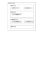
- the screen G1 is a diagram showing an example of a screen G1 displayed on the display unit 201.
- the screen G1 is an example of an operation screen.
- the screen G1 displayed on the display unit 201 displays, for example, a field map G10 showing a stadium F.
- drone icons G11a and G11b showing the photographing device 1000 photographing the stadium F here the first drone 100a and the second drone 100b, respectively, are displayed.
- a first shooting area field G12a showing the area photographed by the first drone 100a, and a second shooting area field G12b showing the area photographed by the second drone 100b are displayed superimposed on the field map G10.
- a first captured image field G40a and a second captured image field G40b showing the images photographed by the drone 100a and drone 100b, respectively, are displayed in association with the drone icons G11a and G11b.
- the blind spot area of the first drone 100a or the second drone 100b may be displayed on the field map G10.
- the user can easily identify the blind spot area A200 that is not captured, even when the stadium F is being captured by multiple cameras whose positions, shooting directions, and zoom amounts can be changed.
- the shooting position and shooting direction of the drones 100a and 100b may be controlled manually, or automatic tracking control of the ball or a specific player may be performed.
- automatic tracking control information about the ball or a specific player to be tracked may be displayed on the screen G1.
- the icons G11a, 11b representing the drones 100a, 100b display an arrow indicating the direction of travel of the drone 100.
- the direction of the nose of the drones 100a, 100b is not limited to the direction of travel of the drones 100a, 100b, and may be pointing in any direction.
- the direction of the nose of the drones 100a, 100b does not have to be constant while moving, and for example, the drones may move by yaw rotation while photographing players or the ball.
- the input control unit 220 shown in Fig. 9 accepts various inputs from a user such as a pilot.
- the input control unit 220 mainly accepts operations for an operation target device.
- the operation target device is, for example, any one of the drone 100, the mobile camera 710, and the fixed camera 720.
- the input control unit 220 accepts which operation target device is to be operated by an operation target switching unit 225 described later.
- the input control unit 220 of this embodiment mainly has the following functional units: a moving object position operation unit 221, a moving object attitude operation unit 222, a camera attitude operation unit 223, a camera zoom operation unit 224, an operation target switching unit 225, an automatic/manual switching unit 226, a target area selection unit 227, and a power input unit 229.
- the operation unit 221 for the moving body position includes an up-down movement input unit 221a and a left-right movement input unit 221b.
- the operation unit 222 for the moving body attitude includes a forward-backward movement input unit 222a and a yaw rotation input unit 222b.
- the up-down movement input unit 221a is an input unit for allowing the operator to move the target device up and down, and acquires input to the right input stick 327R. That is, when the right input stick 327R is moved upward (toward the back when held in the hand), the target device rises, and when the right input stick 327R is moved downward (toward the front when held in the hand), the target device descends.
- the left-right movement input unit 221b is an input unit for allowing the operator to move the target device left and right, and acquires input to the right input stick 327R. That is, when the right input stick 327R is moved to the right, the target device moves to the right, and when the right input stick 327R is moved to the left, the target device moves to the left.
- the forward/backward movement input unit 222a is an input unit for allowing the operator to move the target device forward/backward, and acquires input to the left input stick 327L. That is, when the left input stick 327L is moved upward (toward the rear when held in the hand), the target device moves forward, and when the left input stick 327L is moved downward (toward the front when held in the hand), the target device moves backward.
- the yaw rotation input unit 222b is an input unit for allowing the operator to yaw rotate the target device, and acquires input to the left input stick 327L. That is, when the left input stick 327L is moved to the right, the target device turns right, and when the left input stick 327L is moved to the left, the target device turns left.
- mobile camera 710 can only move by sliding on guide rail 7126, if mobile camera 710 is specified as the device to be operated and a movement operation is input in a direction in which movement is not possible, the operation may be invalidated. Also, fixed camera 720 cannot move, so if fixed camera 720 is specified as the device to be operated, the movement operation is invalidated.
- the camera attitude operation unit 223 is an input unit for operating the camera holding unit 142 via the imaging control unit 143 and for controlling the orientation of the imaging cameras 141, 7111, 7211 of the device to be operated.
- the camera attitude operation unit 223 obtains input to the right slider 326R.
- the camera attitude operation unit 223 accepts operation of either or both of the pitch angle and yaw angle of the imaging cameras 141, 7111, 7211.
- the camera zoom operation unit 224 is an input unit for operating the shooting magnification, i.e., the zoom amount, of the shooting cameras 141, 7111, and 7211, and obtains input to the left slider 326L.
- the operation target switching unit 225 is a functional unit that switches the operation target that transmits the command input to the control device 200.
- the operation target switching unit 225 determines the operation target to be either the drone 100, the mobile camera 710, or the fixed camera 720, for example, based on an appropriate signal input to the control device 200.
- the automatic/manual switching unit 226 is a functional unit that switches between automatic and manual control of the device to be operated.
- the controlled device switching unit 225 determines whether to operate automatically or manually, for example, based on an appropriate signal input to the control device 200.
- At least one of the controlled devices, the drone 100, the mobile camera 710, and the fixed camera 720, is capable of both automatic and manual control.
- the target area selection unit 227 is a functional unit that accepts input of the target area to be photographed by the photographing camera 141, 1711, or 1721.
- the target area selection unit 227 accepts input of a point on the stadium F.
- the target area selection unit 227 may accept input of the target area via a touch panel display that is configured integrally with the display unit 201 when at least a portion of an image or schematic diagram of the stadium F is displayed on the display unit 201.
- FIG. 13 is an example of a target area table T1 showing the correspondence between the identification numbers of multiple target areas set by subdividing the stadium F and the three-dimensional coordinates indicating the outer edge of each target area.
- the multiple target areas included in the target area table T1 may include areas of various sizes, or may include areas that overlap with each other.
- the target area selection unit 227 may accept a selection of a target area included in the target area table T1. Furthermore, when the target area selection unit 227 accepts the specification of an arbitrary position within the stadium F via the touch panel display, it may refer to the target area table T1 and identify the selected target area by extracting the target area to which the position belongs.
- the shooting mode setting unit 228 is a functional unit that sets the shooting mode of the shooting device 1000.
- the shooting modes include, for example, a tracking shooting mode and an overhead shooting mode.
- the tracking shooting mode is a shooting mode in which the ball is automatically tracked and photographed.
- the overhead shooting mode is a shooting mode in which the inside of the stadium F is photographed regardless of the position of the ball.
- the tracking shooting mode is a shooting mode in which the zoom amount is larger than that of the overhead shooting, for example, and the shooting is focused on the subject B.
- the overhead shooting mode may be a mode in which a wider shooting area is photographed than the tracking shooting mode.
- the shooting modes may also include other shooting modes such as a manual shooting mode and an automatic shooting mode.
- the power input unit 229 is a functional unit that accepts the power on/off command for the control device 200 via the power button 328.
- the input control unit 220 may be capable of receiving touch input to the display unit 201 and transmitting control commands to the drone 100 or the mobile camera 710 in response to the input. More specifically, for example, when the user selects appropriate information such as a map or schematic diagram displayed on the display unit 201, a route to the selected point may be automatically generated, causing the drone 100 or the mobile camera 710 to move autonomously.
- the communication unit 240 is a functional unit that transmits and receives signals between the control device 200 and an appropriate configuration included in the system 1.
- the control device 200 has a communication function that performs wireless communication with the drone 100 by wireless communication using Wi-Fi, 2.4 GHz, and 5.6 to 5.8 GHz frequency bands.
- the control device 200 also has a wireless communication function that can communicate with the server 300 via the communication network 400 using a communication standard such as LTE (Long Term Evolution).
- the communication unit 240 transmits various input signals by a user such as a pilot to the drone 100 or the server 300.
- the communication unit 240 also receives signals from the drone 100, the mobile camera 710, the fixed camera 720, the server 300, or the like.
- the server 300 manages or controls the movement and photography of the photographing devices 1000.
- the server 300 controls a plurality of photographing devices 1000, and after referring to the photographing range of a first photographing device 1000, determines the photographing mode of the other photographing devices 1000 so that the area not photographed by the first photographing device 1000 is supplemented by the other photographing devices 1000 and controls the other photographing devices 1000.
- the present system 1 determines the photographing mode of the second drone 100b by referring to the photographing range of the first drone 100a.
- the first and second photographing devices 1000 may be mobile cameras 710 or fixed cameras 720. That is, the present system 1 may determine the photographing mode of the mobile camera 710 or the fixed camera 720 by referring to the photographing range of the drone 100.
- the server 300 may determine the photographing mode of the drone 100, another mobile camera 710, or the fixed camera 720 by referring to the photographing range of the mobile camera 710.
- the server 300 may determine the photographing mode of the drone 100, the mobile camera 710, or the fixed camera 720 by referring to the photographing range of the fixed camera 720.
- the server 300 may be a general-purpose computer such as a workstation or personal computer, or may be logically realized by cloud computing.
- the server 300 is equipped with a calculation device such as a CPU for executing information processing, and storage devices such as RAM and ROM, which constitute the software configuration of the following main functional blocks: target area determination unit 310, camera information acquisition unit 320, blind spot area determination unit 330, photographed object position estimation unit 340, event detection unit 350, camera control command unit 360, communication unit 370, and memory unit 380.
- the server 300 also has an input/output unit (not shown) for inputting or outputting various types of information (image output, audio output).
- the target area determination unit 310 is a functional unit that determines the area that should be photographed by any one of the photographing cameras 141, 7111, and 7211, that is, the target area.
- the target area determination unit 310 mainly includes a target area information acquisition unit 311 and a target area recognition unit 312 .
- the target area information acquisition unit 311 receives information on the target area received, for example, via the target area selection unit 227 of the control device 200.
- the target area information acquisition unit 311 may also determine that the area that includes the subject B to be photographed is the target area.
- the target area recognition unit 312 is a functional unit that refers to the target area table T1 (see FIG. 13) and recognizes the three-dimensional coordinates of the accepted target area.
- the camera information acquisition unit 320 is a functional unit that acquires information related to the photographing camera 141 of the first drone 100a.
- the camera information acquisition unit 320 includes a camera position/attitude information acquisition unit 321, a photographed image acquisition unit 322, and a photographing mode acquisition unit 323.
- the camera position and orientation information acquisition unit 321 acquires information on the position and orientation of the shooting camera 141.
- the captured image acquisition unit 322 is a functional unit that acquires the captured image taken by the imaging camera 141.
- the shooting mode acquisition unit 323 is a functional unit that acquires the shooting mode set in the first drone 100a. In particular, the shooting mode acquisition unit 323 acquires whether or not the first drone 100a is in tracking shooting mode.
- the blind spot area determination unit 330 is a functional unit that determines a blind spot area A200 that is not photographed by the first photographing device 1000, out of the target area A110 to be photographed.
- the blind spot area determination unit 330 mainly includes a shooting area determination unit 331 , an outside-of-view-angle area determination unit 332 , and a shadow area determination unit 333 .
- FIG. 14 is a schematic diagram showing the first drone 100a taking pictures at the stadium F, and the shooting area A100a of the first drone 100a.
- the shooting area A100a is the area that is captured by the shooting camera 141 of the first drone 100a. In other words, the area included in the shooting area A100a is shown in the captured image G100a.
- the area of the stadium F that is not included in the shooting area A100a is not captured by the shooting camera 141.
- the area that is not included in the shooting area A100a is a first example of a blind spot area.
- the target area A110 indicates the range that is set as the area to be photographed.
- the target area A110 may be an area that is automatically determined by an appropriate functional unit of the present system 1, or may be an area specified by the user.
- the target area A110 is an area that includes the subject B to be photographed, and may be an area identified by image analysis of the photographed image.
- the subject B to be photographed is, for example, a ball, but is not limited to an object and may be a player, etc.
- the subject B to be photographed may be an object that is preset in the present system 1, or may be selected by the user.
- the subject B to be photographed may be something that moves within the stadium F.
- Area A200 of the target area A110 that is not included in the shooting area A100a cannot be photographed by the first drone 100a even though it requires shooting.
- this area A200 is defined as a blind spot area A200.
- Area A200 is a second example of a blind spot area. Because the blind spot area A200 cannot be photographed by the first drone 100a, shooting is performed by another drone 100b, a mobile camera 710, or a fixed camera 720 under the control of the system 1.
- the blind spot area A200 mainly includes an outside-of-view area A210 and a shadow area A220.
- the outside-of-view area A210 is an area that is not included in the angle of view of the shooting area A100.
- the shadow area A220 is an area that is included in the angle of view of the shooting area A100 but is hidden behind an obstruction P and is not photographed.
- An obstruction P is, for example, a group of players who are closely packed together. Note that the obstruction P may be a single player, or it may be any suitable object, such as an object, an animal such as a bird, fixed equipment, or various kinds of equipment used in sports such as a ball.
- the photographing area determination unit 331 extracts the photographing area A100a of the first drone 100a based on the information acquired by the camera information acquisition unit 320. For example, the photographing area determination unit 331 extracts the photographing area A100a based on the image captured by the photographing camera 141 of the first drone 100a.
- the shooting area determination unit 331 may also extract the shooting area A100 based on the position and direction of the camera and the zoom amount instead of or in addition to the information on the captured image. If the playing area for soccer or the like is a stadium F, the stadium F is approximately point-symmetric, so the shooting area cannot be uniquely identified based on the captured image information alone. In this regard, if the shooting area determination unit 331 is configured to extract the shooting area by referring to the information on the position and direction of the drone 100, the shooting area can be uniquely identified.
- the outside-of-view area determination unit 332 is a functional unit that identifies the outside-of-view area A210 that is not included in the angle of view of the shooting area A100.
- the outside-of-view area determination unit 332 determines the outside-of-view area based on information on the shooting area A100 determined by the shooting area determination unit 331 and information on the target area A110 to be photographed recognized by the target area recognition unit 312. In other words, the outside-of-view area determination unit 332 determines that an area of the target area A110 that is not included in the shooting area A100 is the outside-of-view area A210.
- the outside-of-angle-of-view area determination unit 332 may compare the shooting area A100 of all cameras 141, 1711, 1721 with each of the divided areas into which the court F100 is divided into a predetermined number of areas, in order to always keep the entire court F100 within the angle of view, and determine whether all of the divided areas are being shot by at least one of the cameras.
- the shadow area determination unit 333 is a functional unit that identifies shadow areas A220 that are included in the angle of view of the photographed area A100 but are hidden behind an obstruction and not photographed. For example, the shadow area determination unit 333 performs image analysis on the photographed image to identify the obstruction and determine the coordinates of the shadow area A220. The shadow area determination unit 333 determines that an area where multiple players are crowded together is a shadow area A220. The shadow area determination unit 333 may determine that one shadow area A220 is formed by multiple players. The shadow area determination unit 333 may also determine multiple shadow areas A220 simultaneously in one stadium F.
- the blind spot area determination unit 330 may predict the blind spot area A200 from the current time onward. For example, the blind spot area determination unit 330 predicts the shooting area A100a of the first drone 100a based on the moving direction and moving speed of the first drone 100a. In addition, instead of or in addition to predicting the shooting area A100a, the blind spot area determination unit 330 may predict the target area A110 from the current time onward based on the moving direction and moving speed of the target area A110 when the target area A110 moves based on the movement of the shooting target B or a predetermined setting.
- the blind spot area determination unit 330 predicts the position and range of the outside angle of view area A210 based on the prediction result of at least one of the shooting area A100a and the target area A110 from the current time onward. With this configuration, even if the shooting target B moves faster than the drone 100, it is possible to track and shoot more quickly.
- the blind spot area determination unit 330 may also predict the shadow area A220 from the current time onwards.
- the blind spot area determination unit 330 may estimate the type of obstruction that constitutes the shadow area A220, and estimate the direction and speed of movement of the shadow area A220 according to the type of obstruction.
- the blind spot area determination unit 330 predicts the position and range of the shadow area A220 after a predetermined time based on the position of the obstruction after a predetermined time and the position of the first drone 100a. With this configuration, the shadow area A220 of the first drone 100 can be reliably photographed by the second drone 100b.
- the photographing target position estimating unit 340 is a functional unit that estimates the position of a predetermined photographing target B set in the present system 1 .
- the photographed object position estimation unit 340 performs image analysis on the image captured by the photographing equipment 1000.
- the photographed object position estimation unit 340 also estimates the position of the photographed object B in the stadium F based on the position, direction, and zoom amount of the photographing equipment 1000 that captured the image in which the photographed object B appears, and the position of the photographed object B in the captured image.
- the position of the photographed object B may be expressed in two-dimensional coordinates or three-dimensional coordinates.
- the photographed object position estimation unit 340 may estimate the change in position of the photographed object B.
- the photographed object position estimation unit 340 may analyze a number of images captured at different times, and estimate the change in position of the photographed object B.
- the photographed object position estimation unit 340 may estimate the moving direction or moving speed of the photographed object B.
- the photographing subject position estimation unit 340 estimates the position of the subject B based on a past photographed image captured by the photographing device 1000.
- the photographing subject position estimation unit 340 refers to a past photographed image captured immediately before the subject B moves outside the photographed image, and estimates the moving direction of the subject B to estimate the current position of the subject B.
- the photographing subject position estimation unit 340 may also estimate the moving speed of the subject B in addition to the moving direction to estimate the current position of the subject B.
- the object position estimation unit 340 may estimate the position of the object B based on the image captured by the second drone 100b.
- the object position estimation unit 340 may also refer to the image captured by the second drone 100b at the time when the object B moves outside the shooting area A100a, or may refer to the image captured by the second drone 100b before the object B moves outside the shooting area A100a.
- the event detection unit 350 is a functional unit that detects an event that occurs in the stadium F.
- the event detection unit 350 detects an event, for example, by performing image analysis on the actions of the object B to be photographed, the players, the referee, and the like.
- the event detection unit 350 may detect that a long pass has been made when the ball B moves a predetermined distance or more at a predetermined speed or more during a match.
- a long pass is an action of handing the ball over to a player who is far away, and the ball moves a long distance at a relatively fast speed.
- a long pass is a pass in which the ball moves faster than the speed at which the drone 100a can track and photograph it.
- the camera control command unit 360 is a functional unit that transmits a control command to the photographing device 1000.
- the control command from the camera control command unit 360 is a command to control at least one of the position and direction of the photographing device 1000, and the position, direction, and zoom amount of the photographing cameras 141, 7111, and 7211 mounted on the photographing device 1000. That is, the camera control command unit 360 transmits a control command to control the position and direction of the photographing device 1000.
- the camera control command unit 360 transmits a control command to control the photographing direction and zoom amount of the photographing cameras 141, 7111, and 7211 mounted on the photographing device 1000.
- the camera control command unit 360 may transmit a control command to control the position of the photographing cameras 141, 7111, and 7211.
- the camera control command unit 360 controls the first drone 100a so that the specified target area A110 is included in the shooting area A100a.
- the camera control command unit 360 may refer to this and control the first drone 100a to the shooting position, shooting direction, or zoom amount according to the specified target area A110.
- the camera control command unit 360 may control the first drone 100a so that the subject B is included in the shooting area A100a of the first drone 100a.
- the camera control command unit 360 transmits a control command to the second drone 100b to cause the second drone 100b to capture an image of an area not captured by the first drone 100a. More specifically, the camera control command unit 360 controls the second drone 100b to capture an image of the blind spot area A200 of the first drone 100a extracted by the blind spot area determination unit 330.
- the capture area A100b of the second drone 100b may include the entire blind spot area A200, or may include at least a portion of the blind spot area A200.
- FIG. 15 is a schematic diagram showing how the second drone 100b photographs an area not photographed by the first drone 100a.
- the first drone 100a tracks and photographs the subject B, while the second drone 100b photographs the stadium F from above.
- the photographing area A100b of the second drone 100b includes at least a portion of the blind spot area A200.
- the multiple drones 100 can capture the entire game.
- the area around the object B such as a ball
- the formation of the players changes not only around the object B, so it is also necessary to capture the entire game.
- the first drone 100a tracks and captures the object B
- the position, shooting direction, and zoom amount of the first drone 100a change from moment to moment, resulting in a quick change in the shooting area A100a and a movement of the blind spot.
- the zoom amount is increased to capture the object B more fully, an even wider blind spot occurs. In other words, many blind spots occur with only the first drone 100a.
- the second drone 100b can supplement and capture the area around the first drone 100a, so it is possible to capture the area of interest where the object B is located and the movements of the players in the entire stadium F, and capture the entire game.
- the target area determination unit 310 recognizes the target area (step S101).
- the camera information acquisition unit 320 acquires information about the camera (step S102).
- the blind spot area determination unit 330 determines the blind spot area A200 (see Fig. 14) (step S103).
- the camera control command unit 360 controls the photographing unit 140 (step S104). Note that in step S104, the camera control command unit 360 may control at least one of the photographing unit 140, the mobile camera 710, and the fixed camera 720.
- the blind spot area A200 of the first drone 100a can be supplemented by the second drone 100b, allowing the entire competition to be filmed. This allows for precise and objective analysis when this footage is used for coaching or reflection on the competition. Furthermore, when this footage is used for spectator purposes, spectators can be made even more entertained by being able to watch every detail of the competition.
- the camera control command unit 360 may control multiple other cameras, including the second drone 100b, to capture the blind spot area A200 of the first drone 100a.
- Fig. 17 is a schematic diagram showing three or more drones 100 shooting one stadium F.
- the first drone 100a, the second drone 100b, the third drone 100c, and the fourth drone 100d are shooting the shooting areas A100a, A100b, A100c, and A100d, respectively, in the stadium F.
- At least three of the first drone 100a, the second drone 100b, the third drone 100c, and the fourth drone 100d are shooting by focusing on a local area, rather than shooting from an overhead angle.
- the camera control command unit 360 refers to the blind spot area A200 of the first drone 100a and controls the second drone 100b, the third drone 100c and the fourth drone 100d so that the blind spot area A200 is included in the shooting area A100b, A100c, A100d of any of the second drone 100b, the third drone 100c and the fourth drone 100d.
- FIG. 18 is an example of capturing an image of the shadow area A220 in the first drone 100a so as to be included in the shooting area A100b of the second drone 100b.
- a crowded area A300 occurs in the shooting area A100a of the first drone 100a.
- this crowded area A300 is an area where multiple players are crowded.
- the rear side of the crowded area A300 as seen from the first drone 100a is the shadow area A221.
- FIG. 18(c) is a schematic diagram showing the second drone 100b capturing an image of the shooting area A100b including the shadow area A221.
- the second drone 100b flies to a position opposite the first drone 100a in response to a command from the camera control command unit 360, and captures the crowded area A300 from the opposite side to the first drone 100a.
- the shadow area A221 can be captured without omission.
- the camera control command unit 360 may refer to the area of the shooting area A100a of the first drone 100a and control the second drone 100b so that the area of the shooting area A100b of the second drone 100b is larger than the shooting area A100a. With this configuration, there is a high probability that the second drone 100b can capture areas that are not included in the shooting area A100a, so the competition can be captured more thoroughly.
- the camera control command unit 360 may also refer to the shooting mode of the first drone 100a, and when the first drone 100a is in the tracking shooting mode and tracking and shooting a specified shooting object B, control the second drone 100b to take an overhead shot of an area wider than the shooting area A100 of the first drone 100a.
- the camera control command unit 360 may fly the first drone 100a and the second drone 100b facing each other along a pair of touchlines F111a, F111b or a pair of goal lines F110a, F110b of the stadium F, thereby complementing each other's blind spot areas and taking photographs.
- the camera control command unit 360 may cause one of the first drone 100a and the second drone 100b to fly along the touch line F111a or F111b, and the other to fly along the goal line F110a or F110b.
- Figure 19 is a schematic diagram showing two drones 100a and 100b facing each other and taking pictures.
- FIG. 19(a) shows the first drone 100a and the second drone 100b facing each other along a pair of touch lines F111a, F111b to take pictures.
- the shooting areas A100a, A100b of the first drone 100a and the second drone 100b extend beyond the center, and the shooting areas A100a, A100b overlap each other in the center.
- FIG. 19(b) shows the first drone 100a and the second drone 100b facing each other along a pair of goal lines F110a, F110b to take pictures. Even in this case, the shooting areas A100a, A100b of the first drone 100a and the second drone 100b extend beyond the center, and the shooting areas A100a, A100b overlap each other in the center.
- Figure 19(c) shows the first drone 100a and the second drone 100b facing each other and taking pictures in yet another manner.
- the first drone 100a and the second drone 100b fly in one side area and the other side area of the halfway line F150, respectively.
- the drone 100 takes pictures inside the court F100, and one of the shooting areas A100a, A100b extends to the rear of the other shooting areas A100b, A100a.
- the communication unit 370 has a modem or the like (not shown) and is capable of communicating with the photographing equipment 1000, the control device 200, and the like via the communication network 400.
- the storage unit 380 is a functional unit that stores data necessary for controlling a plurality of image capturing devices 1000 .
- the storage unit 380 includes a target area information storage unit 371.
- the target area information storage unit 371 stores a target area table T1 shown in FIG. 13.
- the target area table T1 is primarily referenced by the target area determination unit 310 and the outside-angle-of-view area determination unit 332 as appropriate.
- FIG. 20 is a flowchart showing the processing when the object to be photographed B moves outside the photographing area A100a of the first drone 100a.
- FIG. 21 is a schematic diagram showing an example of a situation in which the processing according to the flowchart is performed.
- the event detection unit 350 detects a long pass (Y in step S201).
- a long pass is made by a player on the court F100. Therefore, as shown in FIG. 21(b), the object to be photographed B deviates outside the photographing area A100a.
- the photographing subject position estimation unit 340 predicts the trajectory of ball B upon detection of the long pass (step S202).
- the camera control command unit 360 controls the first drone 100a so that the future position of ball B is included in the photographing area A100a according to the prediction result of the trajectory of ball B (step S203).
- the camera control command unit 360 also controls the second drone 100b to change the photographing area A100b so that the outside-angle-of-view area A210 of the first drone 100a is included in the photographing area A100b of the second drone 100b (step S204).
- the position, direction, or zoom amount of the second drone 100b is different from that before the long pass was detected.
- Figure 22 shows another example of the case where ball B moves outside the shooting area A100a of the first drone 100a.
- ball B quickly moves from the shooting area A100a of the first drone 100a to the lower right as indicated by the arrow in the figure, and deviates from the shooting area A100a.
- the moving speed of ball B is faster than the speed at which the first drone 100a can track and photograph it.
- the subject B deviates outside the angle of view.
- the second drone 100b photographs the court F100 from above, and the shooting area A100b encompasses almost the entire surface of the court F100. Therefore, the subject B is also captured in the image captured after the deviation as shown in Figure 21(c).
- the position of the photographed object B is estimated by the photographed object position estimation unit 340 based on the image of the photographed area A100b.
- the camera control command unit 360 controls the position, photographing direction, or zoom amount of the first drone 100a based on the position of the photographed object B.
- the photographed object B is again included in the photographed area A100a.
- FIG. 23 shows yet another example of a case where ball B moves outside the shooting area A100a of the first drone 100a.
- ball B quickly moves from the shooting area A100a of the first drone 100a to the lower right as indicated by the arrow in the figure, and deviates from the shooting area A100a.
- the moving speed of ball B is faster than the speed at which the first drone 100a can track and photograph it.
- the subject B deviates outside the angle of view.
- ball B also deviates from the shooting area A100b of the second drone 100b, as shown in FIG. 23(c).
- the position of the photographed object B is estimated by the photographed object position estimation unit 340 based on past images of the photographed area A100b.
- the camera control command unit 360 controls the position, photographing direction, or zoom amount for at least one of the first drone 100a and the second drone 100b based on the estimated position of the photographed object B.
- the photographed object B is again included in the photographed area A100a.
- the camera control command unit 360 may control the position of the drone 100 based on the remaining battery power of the drone 100, and may switch the drone 100 photographing the stadium F by having another drone 100b supplement and photograph the photographing area A100a of the drone 100a with low battery power.
- FIG. 24 is a flowchart showing an example of a process for switching drones 100 when the remaining battery power decreases.
- FIG. 25 and FIG. 26 are schematic diagrams showing the state of the stadium F when switching drones 100.
- the process of switching the drone 100 shown in FIG. 24 can also be applied when an abnormal or broken state of the drone 100 or the photographing camera 141 is detected, other than when the drone is switched due to a drop in the remaining battery level.
- the abnormal state means a reversible temporary abnormal state, and includes, for example, a state in which the temperature of the equipment mounted on the drone 100 rises above a predetermined value, a state in which the lens of the photographing camera 141 becomes cloudy or dirty, and a state in which an abnormality occurs in the rotation speed of the propellers 122 of the drone 100 (such as a state in which only one propeller has a higher rotation speed than the other propellers).
- a broken state means a state in which an irreversible problem has occurred, such as a failure of various sensors such as a geomagnetic sensor or a state in which vibrations of an abnormal strength are occurring in the aircraft. Even if it is detected that the drone or camera has become broken, if the failure mode or degree of failure is such that there is no risk of an immediate crash, it is desirable not to immediately start a landing operation, but to wait until the arrival of the third drone 100c before switching to photographing.
- the camera control command unit 360 measures the remaining battery charge of the first drone 100a photographing the stadium F using an appropriate method, and determines whether the remaining battery charge is equal to or lower than a predetermined value (step S301). If the remaining battery charge is equal to or lower than the predetermined value, the camera control command unit 360 moves the third drone 100c to the position of the first drone 100a (step S302). If the third drone 100c photographs approximately the same area as the photographing area A100a of the first drone 100a (Y in step S303), the third drone 100c stops moving toward the position of the first drone 100a (step S304). Next, the first drone 100a retreats outside the court F100 (step S305).
- step S303 may be made that the same area is being photographed when the photographed areas A100a and A100b are completely identical, or when areas that overlap by a certain amount or more are being photographed.
- the third drone 100c may enter the court F100 at an altitude higher than the shooting altitude of the first drone 100a, and then lower its altitude near the first drone 100a. With this configuration, the third drone 100c moves within the court F100 at a sufficiently high altitude, so it does not interfere with the game and can also be prevented from entering the shooting range of the first drone 100a.
- step S305 as shown in FIG. 26, the first drone 100a flies the shortest distance toward the outer edge of the court F100, then passes outside the court F100 and moves to a predetermined landing point.
- the drone can retreat to the outside of the court F100 in the shortest time possible, without interfering with the game and ensuring safety within the court F100.
- the first drone 100a may also retreat outside the court F100 so as not to enter the shooting area A100b of the third drone 100c. That is, for example, the camera control command unit 360 generates a flight route that detours around the shooting area A100b and exits the court F100.
- the detour route may be, for example, a route in which the first drone 100a passes through a higher flight altitude than the third drone 100c. That is, the first drone 100a and the third drone 100c fly so that their altitudes are switched at positions adjacent to each other in the court F100. That is, the second drone 100b is lowered and the first drone 100a is raised.
- the first drone 100a may also move to the outer edge of the court F100 by the shortest distance after retreating a predetermined distance in the opposite direction to the shooting direction of the third drone 100c. Even with this configuration, the first drone 100a can be evacuated outside the court F100 by bypassing the shooting area A100b of the third drone 100c.
- the third drone 100c photographs the target area A110, so the above-described configuration ensures that the third drone 100c photographs the target area A110 appropriately.
- the first drone 100a retreats after the third drone 100c completes the shooting area A100a of the first drone 100a, so that the target area A110 can be reliably photographed.
- the drone 100 capturing images is changed when the remaining battery power of the drone 100a decreases.
- the change of the drone 100 may be triggered by other events.
- the change may be triggered by a minor abnormality in the drone 100a, or the change may be triggered by an event in which the drone 100a is replaced by a drone 100 having different functions depending on the scene.
- the blind spot area A200 of the first drone 100a can be supplemented by the second drone 100b, so that it is possible to capture both the area of interest where the subject B is located and the movements of the athletes in the entire stadium F, and capture every corner of the competition. Furthermore, when this video is used for coaching or reflection on the competition, precise and objective analysis is possible. Also, when this video is used for spectator purposes, spectators can enjoy the competition even more by being able to watch every corner of the competition.
- the present invention is not limited to the above embodiment, and various configurations can be adopted based on the contents of this specification.
- the series of processes described in relation to the above embodiment may be implemented using software, hardware, or a combination of software and hardware.
- a computer program for implementing each function of the server 300 according to this embodiment may be created and implemented in a PC or the like.
- a computer-readable recording medium on which such a computer program is stored may also be provided. Examples of the recording medium include a magnetic disk, an optical disk, a magneto-optical disk, and a flash memory.
- the above computer program may also be distributed, for example, via the communication network 400, without using a recording medium.
Landscapes
- Engineering & Computer Science (AREA)
- Multimedia (AREA)
- Signal Processing (AREA)
- Mechanical Engineering (AREA)
- Remote Sensing (AREA)
- Aviation & Aerospace Engineering (AREA)
- Microelectronics & Electronic Packaging (AREA)
- Studio Devices (AREA)
Abstract
Le problème est d'obtenir une image complète d'une compétition. La solution selon l'invention consiste en un système d'imagerie (1) comprenant : une pluralité de corps mobiles (100, 710) qui se déplacent dans une zone de déplacement prescrite ; une première caméra (141) et une seconde caméra (7111) qui sont respectivement montées sur les corps mobiles et qui capturent au moins une partie d'un champ cible d'imagerie (F) ; et une unité d'instruction de commande de caméra (360) qui commande, sur la base d'une zone d'imagerie imagée par la première caméra, la seconde caméra de façon à imager une zone aveugle (A200) qui n'est pas capturée par la première caméra.
Priority Applications (2)
| Application Number | Priority Date | Filing Date | Title |
|---|---|---|---|
| JP2024576012A JPWO2024166318A1 (fr) | 2023-02-09 | 2023-02-09 | |
| PCT/JP2023/004425 WO2024166318A1 (fr) | 2023-02-09 | 2023-02-09 | Système d'imagerie, procédé d'imagerie et programme d'imagerie |
Applications Claiming Priority (1)
| Application Number | Priority Date | Filing Date | Title |
|---|---|---|---|
| PCT/JP2023/004425 WO2024166318A1 (fr) | 2023-02-09 | 2023-02-09 | Système d'imagerie, procédé d'imagerie et programme d'imagerie |
Publications (1)
| Publication Number | Publication Date |
|---|---|
| WO2024166318A1 true WO2024166318A1 (fr) | 2024-08-15 |
Family
ID=92262142
Family Applications (1)
| Application Number | Title | Priority Date | Filing Date |
|---|---|---|---|
| PCT/JP2023/004425 Ceased WO2024166318A1 (fr) | 2023-02-09 | 2023-02-09 | Système d'imagerie, procédé d'imagerie et programme d'imagerie |
Country Status (2)
| Country | Link |
|---|---|
| JP (1) | JPWO2024166318A1 (fr) |
| WO (1) | WO2024166318A1 (fr) |
Citations (4)
| Publication number | Priority date | Publication date | Assignee | Title |
|---|---|---|---|---|
| JP2016177740A (ja) * | 2015-03-23 | 2016-10-06 | グローリー株式会社 | 人物認証装置、人物認証システム及び人物認証方法 |
| JP2017027355A (ja) * | 2015-07-22 | 2017-02-02 | 鹿島建設株式会社 | 監視装置 |
| JP2021166316A (ja) * | 2018-06-18 | 2021-10-14 | ソニーグループ株式会社 | 移動体及び制御方法 |
| JP2022110448A (ja) * | 2021-01-18 | 2022-07-29 | 京セラ株式会社 | 運転支援システム、車両、撮影装置 |
-
2023
- 2023-02-09 JP JP2024576012A patent/JPWO2024166318A1/ja active Pending
- 2023-02-09 WO PCT/JP2023/004425 patent/WO2024166318A1/fr not_active Ceased
Patent Citations (4)
| Publication number | Priority date | Publication date | Assignee | Title |
|---|---|---|---|---|
| JP2016177740A (ja) * | 2015-03-23 | 2016-10-06 | グローリー株式会社 | 人物認証装置、人物認証システム及び人物認証方法 |
| JP2017027355A (ja) * | 2015-07-22 | 2017-02-02 | 鹿島建設株式会社 | 監視装置 |
| JP2021166316A (ja) * | 2018-06-18 | 2021-10-14 | ソニーグループ株式会社 | 移動体及び制御方法 |
| JP2022110448A (ja) * | 2021-01-18 | 2022-07-29 | 京セラ株式会社 | 運転支援システム、車両、撮影装置 |
Also Published As
| Publication number | Publication date |
|---|---|
| JPWO2024166318A1 (fr) | 2024-08-15 |
Similar Documents
| Publication | Publication Date | Title |
|---|---|---|
| US11573562B2 (en) | Magic wand interface and other user interaction paradigms for a flying digital assistant | |
| US12416918B2 (en) | Unmanned aerial image capture platform | |
| US11644832B2 (en) | User interaction paradigms for a flying digital assistant | |
| US12498714B2 (en) | Systems and methods for UAV flight control | |
| US10377484B2 (en) | UAV positional anchors | |
| US12007763B2 (en) | Magic wand interface and other user interaction paradigms for a flying digital assistant | |
| WO2016168722A1 (fr) | Interface baguette magique et autres paradigmes d'interaction d'utilisateur pour un assistant numérique volant | |
| CN113795803B (zh) | 无人飞行器的飞行辅助方法、设备、芯片、系统及介质 | |
| CN112154654A (zh) | 比赛拍摄方法、电子设备、无人机与存储介质 | |
| JP2021113005A (ja) | 無人航空機システムおよび飛行制御方法 | |
| US12174629B2 (en) | Information processing apparatus, information processing method, program, and information processing system | |
| WO2024166318A1 (fr) | Système d'imagerie, procédé d'imagerie et programme d'imagerie | |
| WO2024252444A1 (fr) | Système de détermination, procédé de détermination et programme de détermination | |
| WO2024189898A1 (fr) | Système d'imagerie, procédé d'imagerie et programme d'imagerie | |
| WO2024069789A1 (fr) | Système d'imagerie aérienne, procédé d'imagerie aérienne et programme d'imagerie aérienne | |
| WO2024069788A1 (fr) | Système de corps mobile, système de photographie aérienne, procédé de photographie aérienne, et programme de photographie aérienne | |
| WO2024069790A1 (fr) | Système de photographie aérienne, procédé de photographie aérienne et programme de photographie aérienne | |
| WO2024180639A1 (fr) | Système d'imagerie, procédé d'imagerie, dispositif de commande de corps mobile et programme | |
| JP7777368B2 (ja) | 飛行制御システム、及び飛行制御方法 | |
| WO2024018643A1 (fr) | Système d'imagerie, procédé d'imagerie, dispositif de commande d'imagerie et programme | |
| WO2023238208A1 (fr) | Système de photographie aérienne, procédé de photographie aérienne et dispositif de gestion de corps mobile aérien | |
| WO2025052526A1 (fr) | Système d'imagerie utilisant un aéronef sans pilote, procédé d'imagerie et programme |
Legal Events
| Date | Code | Title | Description |
|---|---|---|---|
| 121 | Ep: the epo has been informed by wipo that ep was designated in this application |
Ref document number: 23921149 Country of ref document: EP Kind code of ref document: A1 |
|
| WWE | Wipo information: entry into national phase |
Ref document number: 2024576012 Country of ref document: JP |
|
| NENP | Non-entry into the national phase |
Ref country code: DE |
|
| 122 | Ep: pct application non-entry in european phase |
Ref document number: 23921149 Country of ref document: EP Kind code of ref document: A1 |