WO2024166318A1 - Imaging system, imaging method, and imaging program - Google Patents
Imaging system, imaging method, and imaging program Download PDFInfo
- Publication number
- WO2024166318A1 WO2024166318A1 PCT/JP2023/004425 JP2023004425W WO2024166318A1 WO 2024166318 A1 WO2024166318 A1 WO 2024166318A1 JP 2023004425 W JP2023004425 W JP 2023004425W WO 2024166318 A1 WO2024166318 A1 WO 2024166318A1
- Authority
- WO
- WIPO (PCT)
- Prior art keywords
- camera
- drone
- area
- photographing
- unit
- Prior art date
- Legal status (The legal status is an assumption and is not a legal conclusion. Google has not performed a legal analysis and makes no representation as to the accuracy of the status listed.)
- Ceased
Links
Images


Classifications
-
- B—PERFORMING OPERATIONS; TRANSPORTING
- B64—AIRCRAFT; AVIATION; COSMONAUTICS
- B64U—UNMANNED AERIAL VEHICLES [UAV]; EQUIPMENT THEREFOR
- B64U10/00—Type of UAV
- B64U10/10—Rotorcrafts
- B64U10/13—Flying platforms
- B64U10/14—Flying platforms with four distinct rotor axes, e.g. quadcopters
-
- B—PERFORMING OPERATIONS; TRANSPORTING
- B64—AIRCRAFT; AVIATION; COSMONAUTICS
- B64U—UNMANNED AERIAL VEHICLES [UAV]; EQUIPMENT THEREFOR
- B64U20/00—Constructional aspects of UAVs
- B64U20/80—Arrangement of on-board electronics, e.g. avionics systems or wiring
- B64U20/87—Mounting of imaging devices, e.g. mounting of gimbals
-
- H—ELECTRICITY
- H04—ELECTRIC COMMUNICATION TECHNIQUE
- H04N—PICTORIAL COMMUNICATION, e.g. TELEVISION
- H04N23/00—Cameras or camera modules comprising electronic image sensors; Control thereof
- H04N23/60—Control of cameras or camera modules
- H04N23/66—Remote control of cameras or camera parts, e.g. by remote control devices
-
- H—ELECTRICITY
- H04—ELECTRIC COMMUNICATION TECHNIQUE
- H04N—PICTORIAL COMMUNICATION, e.g. TELEVISION
- H04N23/00—Cameras or camera modules comprising electronic image sensors; Control thereof
- H04N23/60—Control of cameras or camera modules
- H04N23/69—Control of means for changing angle of the field of view, e.g. optical zoom objectives or electronic zooming
-
- H—ELECTRICITY
- H04—ELECTRIC COMMUNICATION TECHNIQUE
- H04N—PICTORIAL COMMUNICATION, e.g. TELEVISION
- H04N23/00—Cameras or camera modules comprising electronic image sensors; Control thereof
- H04N23/60—Control of cameras or camera modules
- H04N23/695—Control of camera direction for changing a field of view, e.g. pan, tilt or based on tracking of objects
-
- H—ELECTRICITY
- H04—ELECTRIC COMMUNICATION TECHNIQUE
- H04N—PICTORIAL COMMUNICATION, e.g. TELEVISION
- H04N23/00—Cameras or camera modules comprising electronic image sensors; Control thereof
- H04N23/90—Arrangement of cameras or camera modules, e.g. multiple cameras in TV studios or sports stadiums
-
- H—ELECTRICITY
- H04—ELECTRIC COMMUNICATION TECHNIQUE
- H04N—PICTORIAL COMMUNICATION, e.g. TELEVISION
- H04N5/00—Details of television systems
- H04N5/222—Studio circuitry; Studio devices; Studio equipment
-
- B—PERFORMING OPERATIONS; TRANSPORTING
- B64—AIRCRAFT; AVIATION; COSMONAUTICS
- B64U—UNMANNED AERIAL VEHICLES [UAV]; EQUIPMENT THEREFOR
- B64U2101/00—UAVs specially adapted for particular uses or applications
- B64U2101/30—UAVs specially adapted for particular uses or applications for imaging, photography or videography
Definitions
- the present invention relates to a photography system, a photography method, and a photography program.
- Patent document 1 discloses a technology for simultaneously flying multiple drones to photograph an object.
- Patent Document 1 had blind spots, or areas of the playing area that could not be photographed, and was therefore unable to capture all of the events occurring on the field being photographed.
- the present invention was made in consideration of the above problems, and aims to provide a photography system that can capture all events that occur in the field being photographed.
- a photography system comprises a plurality of moving objects that move within a predetermined moving area, a first camera and a second camera that are mounted on each of the plurality of moving objects and capture at least a portion of a field to be photographed, and a camera control command unit that controls the second camera based on the photographing area photographed by the first camera so that the second camera photographs a blind spot area not photographed by the first camera.
- the camera control command unit may control at least one of the position, direction, and zoom amount of the second camera.
- the system may further include a blind spot area determination unit that determines, based on the area captured by the first camera, at least one of an area outside the field of view of the first camera and a shadow area within the field of view as the blind spot area, and the camera control command unit may control the second camera to capture the blind spot area with the second camera.
- a blind spot area determination unit that determines, based on the area captured by the first camera, at least one of an area outside the field of view of the first camera and a shadow area within the field of view as the blind spot area
- the camera control command unit may control the second camera to capture the blind spot area with the second camera.
- the system may further include a photographing area determination unit that determines the photographing area of the first camera based on an image photographed by the first camera.
- the system may further include a target area determination unit that determines a target area, which is an area to be photographed in the photographing field, and the blind spot area determination unit may determine the blind spot area based on the position or photographing direction of the first camera and the target area.
- the blind spot area determination unit may predict the blind spot area from the current time onwards, and the camera control command unit may control the second camera based on the predicted blind spot area.
- the system may further include a display control unit that displays at least one of the shooting area and the blind spot area on the operation screen.
- the first camera and the second camera may be mounted on a drone or a device placed on the ground, or may be fixed to a wire and be movable by pulling up or down the wire.
- the camera control command unit may control the other cameras, including the second camera, to capture the blind spot area.
- the camera control command unit may control the second camera to capture an overhead image of a range wider than the image capture area of the first camera when the first camera is tracking and capturing an image of a specific object.
- the first camera and the second camera are mounted on a first drone and a second drone, respectively, and the field to be photographed is a predefined rectangular court surrounded by a pair of touchlines and a pair of goal lines, and the camera control command unit may fly the first drone and the second drone along a pair of touchlines on both sides of the field to be photographed, or a pair of goal lines, or the touchlines and the goal lines, to photograph by complementing each other's blind spot areas.
- the first camera and the second camera are mounted on a first drone and a second drone, respectively, and the field to be photographed has a rectangular court surrounded by a pair of touchlines and a pair of goal lines, and a halfway line connecting the midpoints of the pair of touchlines defined in advance, and the camera control command unit may fly the first drone and the second drone facing each other to photograph a first area and a second area within the court divided by the halfway line, thereby complementing each other's blind spot areas and photographing them.
- the camera may further include a subject position estimation unit that estimates the position of a subject to be photographed, and when the subject to be photographed moves outside the photographing area of the first camera, the subject position estimation unit estimates the position of the subject to be photographed based on an image captured by the second camera, and the camera control command unit may control the first camera so that the subject to be photographed is included in the photographing area of the first camera.
- a subject position estimation unit that estimates the position of a subject to be photographed, and when the subject to be photographed moves outside the photographing area of the first camera, the subject position estimation unit estimates the position of the subject to be photographed based on an image captured by the second camera, and the camera control command unit may control the first camera so that the subject to be photographed is included in the photographing area of the first camera.
- the camera may further include a subject position estimation unit that estimates the position of a subject to be photographed, and when the subject to be photographed moves outside the photographing area of the first camera, the subject position estimation unit estimates the position of the subject to be photographed based on a past image captured by the first camera or the second camera, and the camera control command unit may control at least one of the first camera and the second camera so that the subject to be photographed is included in the photographing area of the first camera or the second camera.
- a subject position estimation unit that estimates the position of a subject to be photographed, and when the subject to be photographed moves outside the photographing area of the first camera, the subject position estimation unit estimates the position of the subject to be photographed based on a past image captured by the first camera or the second camera, and the camera control command unit may control at least one of the first camera and the second camera so that the subject to be photographed is included in the photographing area of the first camera or the second camera.
- the first camera may be mounted on a first drone, and the camera control command unit may move a third drone equipped with a third camera to the position of the first drone when the remaining battery charge of the first drone falls below a predetermined value, or when an abnormality or malfunction of the first drone or the first camera is detected, and may cause the first drone to retreat when the third drone photographs the same area as the photographing area of the first drone.
- a photographing method is a system having a plurality of moving objects moving in a predetermined moving area, and a first camera and a second camera mounted on each of the plurality of moving objects and photographing at least a part of a field to be photographed, the system executing a camera control command step for controlling the second camera to photograph a blind spot area not photographed by the first camera based on the photographing area photographed by the first camera.
- a photography program causes a system having a plurality of moving objects moving within a predetermined moving area, and a first camera and a second camera mounted on each of the plurality of moving objects and photographing at least a portion of a field to be photographed, to execute a camera control command step for controlling the second camera to photograph a blind spot area not photographed by the first camera based on the photographing area photographed by the first camera.
- computer programs can be provided by being stored on various data-readable recording media, or by being made available for download via a network such as the Internet.
- the present invention makes it possible to capture the entire competition.
- FIG. 1 is a diagram showing the overall configuration of an imaging system according to an embodiment of the present invention
- FIG. 2 is a simplified external perspective view of the drone according to the embodiment.
- FIG. 2 is a functional configuration diagram of the drone according to the embodiment.
- FIG. 2 is a simplified external perspective view of the mobile camera according to the embodiment.
- FIG. 2 is a functional configuration diagram of the mobile camera according to the embodiment.
- FIG. 2 is a simplified external perspective view of the fixed camera according to the embodiment.
- FIG. 2 is a functional configuration diagram of the fixed camera according to the embodiment.
- (a) is a simplified front view of the exterior of the control device of the embodiment;
- (b) is a schematic diagram showing the direction in which the drone moves or turns in response to input from the control device.
- FIG. 2 is a functional configuration diagram of the control device according to the embodiment.
- FIG. 2 is a functional configuration diagram of a server according to the embodiment.
- FIG. 2 is a schematic diagram showing a stadium, which is an example of a field to be photographed.
- FIG. 4 is a diagram showing an example of a screen displayed on a terminal of the imaging system.
- 13 is an example of a table showing a correspondence relationship between identification numbers of target areas in the photographing field and three-dimensional coordinates.
- 3 is a schematic diagram showing a target area, a shooting area, and a blind spot area in the shooting field.
- FIG. 1 is a schematic diagram showing a first example of how the subject field is photographed by multiple drones.
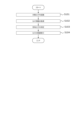
- FIG. 1 is a flowchart of a control executed during flight of the drone.
- 13A, 13B, and 13C are schematic diagrams showing a fourth example, a fifth example, and a sixth example, of the manner in which the subject field is photographed by multiple drones.
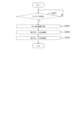
- 13 is a flowchart showing an example of a process when a long path is detected.
- An example of an image of a long pass captured by a first drone (b) A schematic diagram showing how the field to be photographed is photographed by multiple drones at the time the long pass is captured; (c) A schematic diagram showing the appearance of the photography area of the second drone, which has been changed in response to the detection of the long pass.
- Schematic diagrams showing a first example of how the shooting area of a first drone is changed when the ball deviates from the shooting area of the first drone including: (a) an example of an image captured of the ball deviating from the shooting area of the first drone; (b) a schematic diagram showing how the field to be photographed is photographed by multiple drones at the time when the ball's deviation is photographed; (c) an example of an image captured by the second drone at the time when the ball's deviation is photographed; and (d) a schematic diagram showing the appearance of the first drone's shooting area changed in response to the detection of the ball's deviation.
- Schematic diagrams showing a second example of how the shooting area of a first drone is changed when the ball deviates from the shooting area of the first drone (a) an example of a captured image showing the ball deviating from the shooting area of the first drone; (b) a schematic diagram showing the field to be photographed by multiple drones at the time when the ball's deviation is captured; (c) an example of an image captured by the second drone at the time when the ball's deviation is captured; and (d) a schematic diagram showing the first drone's shooting area changed in response to the detection of the ball's deviation.
- 13 is a flowchart illustrating an example of a process for changing drones within the subject field.
- Schematic diagrams showing the state when drones are switched within the field to be photographed including (a) a schematic diagram showing the state in which the field to be photographed is photographed by multiple drones, (b) an example of an image photographed by a first drone, (c) an example of an image photographed by a second drone, and (d) an example of an image photographed by a third drone.
- 1 is a schematic diagram showing a state in which drones are replaced within the field to be photographed.
- FIG. 1 is an overall configuration diagram of a photography system 1 (hereinafter also referred to as "system 1") according to an embodiment of the present invention.
- the system 1 photographs a competition held in a stadium F (FIG. 11) (an example of a field to be photographed) or an event held at an event venue, etc., using a drone 100 (an example of a moving body).
- the field to be photographed refers to a two-dimensional area to be photographed by the drone 100.
- the drone 100 flies in a flight area to photograph the field to be photographed.
- the flight area includes, for example, the field to be photographed, its surroundings, and the sky above them.
- a plurality of drones 100 are included in one system 1, and the system 1 can photograph one stadium F by flying a plurality of drones 100a, 100b at the same time.
- the system 1 may also include a mobile camera 710 or a fixed camera 720 that captures the field to be photographed.
- the mobile camera 710 and the fixed camera 720 are each another example of a camera in the claims.
- the "camera for photography” refers to either the camera for photography 141 of the drone 100, the camera for photography 7111 provided on the mobile camera 710, or the camera for photography 7211 provided on the fixed camera 720.
- the system 1 mainly includes a control device 200 that allows the pilot to operate the drone 100, a server 300 that manages the flight and photography of the drone 100, an external input device 600, an external system 700, a mobile camera 710, and a fixed camera 720.
- the drone 100 and the control device 200 are connected to each other via wireless communication (which may include communication via a base station 800).
- the control device 200 and the server 300 are connected to each other via a communication network 400 such as an Internet line.
- the drone 100 acquires satellite signals from an artificial satellite 500 to determine its own position, etc.
- the external input device 600 is a device capable of transmitting and receiving information to and from the system 1, separate from the control device 200, and is composed of a mobile terminal such as a smartphone or tablet terminal.
- the external input device 600 can be operated, for example, by the manager, coach, bench player, referee, or court facility personnel of the competition taking place at the stadium F.
- the external input device 600 has, for example, a function for receiving an emergency command to stop filming, and the drone 100 performs emergency evacuation based on the command.
- the external input device 600 may also receive an input to switch the flight mode of the drone 100.
- the external input device 600 may be equipped with a display device, and may display information similar to that of the display unit 201 of the control device 200.
- the external input device 600 may acquire event information that occurs during the competition. The event information is referred to when the user of the external input device 600 makes an input to switch the flight mode of the drone 100.
- the external system 700 may be any system configured separately from the system 1. For example, systems such as a court facility system, a match management system, and a referee support system may be applied as systems deployed in relation to the competition held at the stadium F, and systems such as a weather observation system or an earthquake observation system deployed independently of the competition may also be applied. Multiple external systems 700 may be connected to the system 1. The system 1 may receive an emergency command to stop filming or a command to switch the flight mode of the drone 100 from the various external systems 700. In addition, the various external systems 700 may acquire event information that occurs during the competition.
- systems such as a court facility system, a match management system, and a referee support system may be applied as systems deployed in relation to the competition held at the stadium F, and systems such as a weather observation system or an earthquake observation system deployed independently of the competition may also be applied.
- Multiple external systems 700 may be connected to the system 1.
- the system 1 may receive an emergency command to stop filming or a command to switch the flight mode of the drone 100 from the various external systems 700
- the court facilities system which is an example of the external system 700, may obtain the brightness of the captured image from the system 1, for example, and control the illuminance adjustment or blinking of the lighting in the stadium F.
- the court facilities system may also receive a request for lighting illuminance from the system 1 and control the illuminance adjustment or blinking.
- Moveable camera 710 and fixed camera 720 are cameras that capture images of the field to be photographed, and are capable of communicating with each component of system 1, similar to drone 100.
- the drone 100, the mobile camera 710, and the fixed camera 720 are all examples of the photographic equipment 1000 for photographing a specific area of the stadium F.
- the drone 100, the mobile camera 710, and the fixed camera 720 may be collectively referred to as the "photography equipment 1000."
- the number of photographic equipment 1000 included in the system 1 may be any number greater than or equal to two, as long as it is more than one.
- the photographic equipment 1000 may be one or two types of the drone 100, the mobile camera 710, and the fixed camera 720. There may also be multiple photographic equipment 1000 of the same type.
- the drone 100 can be relatively freely controlled in terms of the photographing position, direction, and altitude, so that in order to photograph the target area of the stadium F without omission, it is preferable that at least one of the photographic equipment 1000 is a drone 100.
- the configuration of system 1 is not limited to that shown in FIG. 1, and the drone 100, the control device 200, the server 300, and the base station 800 may each be connected to each other so that they can communicate with each other via a communication network 400 such as an Internet line.
- the drone 100 may perform wireless communication directly with the communication network 400 using a communication method such as LTE without going through the control device 200. Therefore, the drone 100, the control device 200, and the base station 800 do not need to perform direct wireless communication, and it is sufficient if they can each be connected to the communication network 400 in a remote location. Therefore, this is a system configuration that is suitable for a case where the drone 100 and the control device 200 are in a remote location (for example, when a pilot performs remote operation, etc.).
- the drone 100, the control device 200, the base station 800, and the server 300 are each connected to each other so that they can communicate with each other via a communication network 400 such as an Internet line, and the drone 100 and the base station 800 may be communicatively connected to the communication network 400 by satellite communication via an artificial satellite 500.
- a communication network 400 such as an Internet line
- the drone 100 and the base station 800 may be communicatively connected to the communication network 400 by satellite communication via an artificial satellite 500.
- multiple servers 300 may be connected to one drone 100 via multiple communication networks 400, i.e., the system may be made redundant.
- the system may be made redundant.
- the drone 100 and the control device 200 can be controlled even when they are remotely located, making them suitable for remote control, but this is not limited to this, and they can also be applied to visual flight in which the pilot manually controls the drone 100 while watching it.
- the device described in the above embodiment may be realized as a single device, or may be realized by multiple devices (e.g., drone 100, control device 200, cloud server 300) partially or completely connected by communication network 400.
- each functional unit and memory unit of server 300 may be realized by being implemented in different servers 300, drones 100, and control devices 200 connected to each other by communication network 400.
- Fig. 2 is a simplified external perspective view of the drone 100 of this embodiment.
- Fig. 3 is a functional configuration diagram of the drone 100 of this embodiment. As described above, the drone 100 photographs the competition held in the stadium F (Fig. 11) and the event held in the event venue.
- drone refers to any flying object that has the ability to autonomously control its attitude, regardless of the power source (electricity, prime mover, etc.), control method (wireless or wired, and fully autonomous or partially manual, etc.), and whether manned or unmanned.
- Drones are also sometimes referred to as Unmanned Aerial Vehicles (UAVs), flying objects, multicopters, RPAS (Remote Piloted Aircraft Systems), or UAS (Unmanned Aircraft Systems), etc.
- the exterior of the drone 100 is mainly composed of a housing 101 and multiple propellers 122.
- the housing 101 is, for example, a roughly rectangular parallelepiped, but may have any shape.
- Rod-shaped connecting parts 102 extending laterally are connected to the left and right sides of the housing 101.
- the other ends of the connecting parts 102 are respectively connected to propellers 122 and motors 121 that rotate the propellers 122.
- the motors 121 are, for example, electric motors.
- the propellers 122 may be composed of a single propeller, or may be composed of multiple propellers arranged coaxially.
- the number and shape of the blades of each propeller are not particularly limited.
- a propeller guard (not shown) may be provided on the outside of the propeller 122 to prevent the propeller from interfering with obstacles.
- a photographing camera 141 is held by a camera holder 142 below the housing 101.
- an obstacle detection camera 131 is disposed on the front surface of the housing 101.
- the obstacle detection camera 131 is a so-called dual camera consisting of two cameras that form a pair.
- the obstacle detection camera 131 is disposed so as to capture an image in front of the drone 100.
- the obstacle detection camera 131 may be disposed not only on the front surface but also on all surfaces of the housing 101, for example, on six surfaces in the case of a housing 101 that is a substantially rectangular parallelepiped.
- the drone 100 is equipped with an alarm device 250 that alerts people around the drone 100 to the presence of the drone 100.
- the alarm device 250 has, for example, a warning light 251 and a speaker 252.
- the warning light 251 is provided for each propeller 122 or motor 121, and is disposed, for example, on each side of multiple motors 121.
- the warning light 251 may be disposed along the cylindrical side of the motor 121 so that it can be seen from all directions in addition to the front.
- the speaker 242 outputs an alarm sound and is provided in the housing 101 of the drone 100.
- the speaker 242 is provided, for example, on the underside of the housing 101, and transmits the alarm sound downwards of the drone 100.
- the drone 100 is equipped with an arithmetic device such as a CPU (Central Processing Unit) for executing information processing, and storage devices such as a RAM (Random Access Memory) and a ROM (Read Only Memory), and thereby has the following functional blocks: a measurement unit 110, a flight function unit 120, an obstacle detection unit 130, an imaging unit 140, and a communication unit 150.
- an arithmetic device such as a CPU (Central Processing Unit) for executing information processing
- storage devices such as a RAM (Random Access Memory) and a ROM (Read Only Memory)
- the measurement unit 110 is a functional unit that measures information related to the drone 100 or its surroundings.
- the measurement unit 110 has, for example, a position measurement unit 111, a direction measurement unit 112, an altitude measurement unit 113, and a speed measurement unit 114.
- the measurement unit 110 may also include various sensors that acquire information such as temperature, air pressure, wind speed, and acceleration.
- the position measurement unit 111 receives signals from the artificial satellites 500 and measures the position (absolute position) of the aircraft based on the signals.
- the position measurement unit 111 measures its current position using, for example, GNSS (Global Navigation Satellite System), GPS (Global Positioning System), etc., but is not limited to this.
- GNSS Global Navigation Satellite System
- GPS Global Positioning System
- RTK-GNSS Real Time Kinematic - Global Navigation Satellite System
- the position information includes at least two-dimensional coordinate information in a planar view (e.g., latitude, longitude), and preferably includes three-dimensional coordinate information including altitude information.
- the base station 800 which provides information on the reference points of fixed stations used for relative positioning such as RTK, is connected to the drone 100 and the control device 200 so that they can communicate wirelessly, making it possible to measure the position of the drone 100 with greater accuracy.
- the base station 800 can be omitted, or the accuracy of the position coordinate estimation of the base station 800 or drone 100 can be further improved.
- the orientation measurement unit 112 measures the orientation of the aircraft (nose direction, heading direction).
- the orientation measurement unit 112 is composed of a geomagnetic sensor that measures the nose direction (heading direction) of the drone 100 aircraft by measuring geomagnetism, a compass, etc.
- the altitude measurement unit 113 measures the altitude above the ground (hereinafter also referred to as "flight altitude”) as the distance from the ground below the drone 100 (vertically downward).
- the speed measurement unit 114 detects the flight speed of the drone 100.
- the speed measurement unit 114 may measure the speed using a known sensor such as a gyro sensor.
- the flight function unit 120 is a mechanism and function unit that causes the drone 100 to fly, and generates thrust in the drone body for lifting the drone 100 and moving it in a desired direction. As shown in FIGS. 2 and 3 , The flight function unit 120 has a plurality of motors 121, a plurality of propellers 122, and a flight control unit 123.
- the flight control unit 123 independently controls the multiple motors 121 to rotate each propeller 122, causing the drone 100 to perform various operations such as taking off, moving forward, turning, and landing, and controls the attitude angle control and flight operations of the drone 100 from takeoff, during flight, and until landing.
- the flight control unit 123 has a processing unit, also called a flight controller.
- the processing unit may have one or more processors, such as a programmable processor (e.g., a central processing unit (CPU), MPU, or DSP).
- the processing unit has access to a memory (storage unit).
- the memory stores logic, code, and/or program instructions that the processing unit can execute to perform one or more steps.
- the memory may include, for example, a separable medium such as an SD card or RAM, or an external storage device.
- Various data acquired by the measurement unit 110, or video or still image data captured by the imaging camera 141 may be directly transmitted to and stored in the memory. Each data may also be recorded in an external memory.
- the processing unit includes a control module configured to control the state of the drone 100.
- the control module controls the flight function section 120 (thrust generating section) of the drone 100 to adjust the spatial arrangement, attitude angle, angular velocity, angular acceleration, angular velocity and/or acceleration of the drone 100 having six degrees of freedom (translational motion x, y, and z, and rotational motion ⁇ x, ⁇ y, and ⁇ z).
- the flight control unit 123 can control the flight of the drone 100 based on control signals from the pilot device 200 or based on a preset autonomous flight program.
- the flight control unit 123 can also control the flight of the drone 100 by controlling the motor 121 based on various information such as the field to be photographed, flight permitted/prohibited areas, information on the corresponding flight geofences, map information including two-dimensional or three-dimensional map data, the current position information of the drone 100, attitude information (heading information), speed information, and acceleration information, and any combination of these.
- field to be shot refers to a two-dimensional location to be shot (for example, the stadium F).
- FIG. 11 is a schematic diagram showing an example of a playing field F, which is an example of a field to be photographed by a drone, viewed from above.
- the playing field F is composed of a court F100 that is roughly rectangular and is defined by, for example, a straight outer edge, and an outer court area F200 that is a predetermined area that covers the outer edge of the court F100.
- the outer edge of the court F100 is composed of mutually opposing goal lines F110a, F110b and mutually opposing touch lines F111a, F111b that are connected at roughly right angles.
- the connection points of the goal lines F110a, F110b and the touch lines F111a, F111b are the corners F112a, F113a, F112b, F113b.
- Goals F120a, F120b are provided approximately in the center of the pair of goal lines F110a, F110b.
- Penalty areas F130a, F130b are defined in specific areas inside the court F100 adjacent to the goals F120a, F120b, and penalty lines F140a, F140b are drawn on the outer edges of the penalty areas.
- a halfway line F150 is drawn in the center of the court F100, connecting the midpoints of a pair of touchlines and dividing the court F100 into approximately equal parts.
- the halfway line F150 is approximately parallel to the goal lines F110a and F110b.
- goal lines F110a, F110b, touchlines F111a, F111b, penalty lines F140a, F140b, and halfway line F150 are required by the rules for players to play the game, and therefore all of these lines are generally drawn in a manner that allows them to be seen, but the technical scope of the present invention is not limited to this.
- a soccer stadium is used as an example, but the sports that are photographed by the system of the present invention are not limited to soccer, and include any type of sports, such as tennis.
- the subject of the photography is not limited to sports, and the system can also be applied to other events (concerts, ceremonies, etc.).
- an evacuation point H200 is set to which the drone 100 is to be evacuated if an abnormality or malfunction of the drone 100 or the system 1 is detected.
- the abnormality referred to here is an abnormality related to the stability of the aerial movement of the drone 100.
- the abnormality includes, for example, a case where the calculation load associated with the operation control (behavior control, shooting control, etc.) of the drone 100 exceeds a load threshold.
- the abnormality may include a transient abnormality related to the environment, such as a case where the measured value of the behavior control value (e.g. speed) of the drone 100 exceeds an allowable value due to the influence of a strong wind or the like.
- the evacuation point H200 is set outside the touchline F111a and along the touchline F111a. There may be multiple evacuation points H200, and in this embodiment, there are three.
- the evacuation point H220 is set near an extension of the halfway line F150.
- the evacuation points H210 and H230 are set closer to the goals F120a and F120b than the shooting positions L206 and L211.
- the evacuation point H200 for example, the drone 100 is replaced or the battery installed in the drone 100 is changed.
- the obstacle detection unit 130 is a functional unit that detects obstacles around the drone 100.
- the obstacles may include, for example, people, players, objects, animals such as birds, fixed equipment, and the ball.
- the obstacle detection unit 130 measures the position, speed vector, and the like of an obstacle located, for example, below the drone 100 based on the acquired image.
- the obstacle detection unit 130 includes, for example, an obstacle detection camera 131, a ToF (Time of Flight) sensor 132, and a laser sensor 133.
- the ToF sensor 132 measures the time it takes for a laser pulse emitted from the sensor to return to the light receiving element in the sensor, and measures the distance to an object by converting this time into distance.
- the laser sensor 133 uses, for example, the LiDAR (Light Detection And Ranging) method to shine light such as near-infrared light, visible light, or ultraviolet light on the target object and measure the distance by capturing the reflected light with an optical sensor.
- LiDAR Light Detection And Ranging
- FIG. 2 shows that the obstacle detection camera 131 is positioned facing forward, but the type, position and number of the camera 131, ToF sensor 132 and laser sensor 133 are arbitrary, and the ToF sensor 132 or laser sensor 133 may be positioned instead of the camera 131, or the ToF sensor 132 or laser sensor 133 may be provided on all six surfaces of the housing 101, i.e., the front, back, top, bottom and both sides.
- the photographing unit 140 is a functional unit that photographs images of a competition in the stadium F (FIG. 11) or an event in an event venue, and has a photographing camera 141, a camera holding unit 142, and a photographing control unit 143.
- the photographing camera 141 imaging device
- the photographing camera 141 is a video camera (color camera) that photographs moving images.
- the moving images may include audio data acquired by a microphone (not shown).
- the photographing camera 141 may also be configured to photograph still images.
- the orientation of the photographic camera 141 (the attitude of the photographic camera 141 relative to the housing 101 of the drone 100) can be adjusted by a camera actuator (not shown) built into the camera holding unit 142.
- the photographic camera 141 may have an automatic control function for parameters such as exposure, contrast, or ISO.
- the camera holding unit 142 may have a so-called gimbal control mechanism that suppresses the transmission of shaking or vibration of the aircraft to the photographic camera 141.
- the photographic control unit 143 controls the photographic camera 141 and the camera holding unit 142 to adjust the orientation of the photographic camera 141, the photographic magnification (zoom amount), the camera's photographic conditions, etc.
- Image data acquired by the photographic camera 141 can be transmitted to the storage unit of the drone 100 itself, the control device 200, the server 300, etc.
- Communication unit 150 is capable of radio wave communication via communication network 400 and includes, for example, a radio wave communication module. Communication unit 150 is capable of communication with control device 200 and the like via communication network 400 (including wireless base station 800).
- FIG. 4 is a simplified external perspective view of the mobile camera 710 of this embodiment.
- Fig. 5 is a functional configuration diagram of the mobile camera 710 of this embodiment.
- the mobile camera 710 is a device that is placed on the ground and can move along a predetermined route, such as a land-based camera.
- the mobile camera 710 mainly includes, as its hardware configuration, a shooting camera 7111, a camera holding unit 7124, a sliding unit 7125, and a guide rail 7126.
- the photographing camera 7111 is a specific configuration that realizes a photographing function, and is equipped with a lens, an aperture, etc.
- the photographing camera 7111 is a visible light camera, and is a camera that is mainly capable of photographing moving images, but may also be capable of photographing still images, and may also be capable of photographing moving images or still images in frequency ranges other than visible light.
- the camera holding part 7124 is a mechanism that connects the sliding part 7125 and the photographing camera 7111 and holds the photographing camera 7111.
- the camera holding part 7124 holds the photographing camera 7111, for example, above the sliding part 7125.
- the camera holding part 7124 has a rotation axis in a substantially vertical direction, and by rotating the photographing camera 7111, the orientation of the photographing camera 7111 can be changed in the yaw direction.
- the camera holding part 7124 may also be rotatable in the pitch direction, i.e., so that the photographing camera 7111 faces upward or downward.
- the sliding part 7125 is a housing to which the camera holding part 7124 is connected on the upper surface.
- the sliding part 7125 engages with the guide rail 7126 and slides relative to the guide rail 7126.
- a wheel (not shown) may be disposed inside the sliding part 7125 in contact with the guide rail 7126, and the sliding part 7125 may be moved by electrically driving this wheel by the camera position adjustment part 7123 described below.
- the mechanism driven by the camera position adjustment part 7123 may be provided on the guide rail 7126 instead of being disposed on the sliding part 7125.
- the guide rail 7126 is a long member that engages with the sliding portion 7125.
- the guide rail 7126 is placed on a contact surface such as the ground.
- the sliding portion 7125 slides along the guide rail 7126.
- the photographing camera 7111 and its photographing range can move along the guide rail 7126 by the sliding portion 7125 and the guide rail 7126.
- the mobile camera 710 is configured with appropriate components such as a CPU, ROM, and RAM provided in the mobile camera 710, and is configured as software to mainly include functional blocks of an image capture unit 7110, a drive unit 7120, a status acquisition unit 7130, and a communication unit 7140.
- the photographing unit 7110 is a functional unit that photographs the subject.
- the photographing unit 7110 controls the photographing camera 7111 via the camera control unit 7112 to photograph the target area.
- the camera control unit 7112 controls whether the photographing camera 7111 photographs or not, as well as the photographing conditions set inside the photographing camera 7111, such as the zoom amount and F-number of the photographing camera 7111.
- the driving unit 7120 is a functional unit that controls the position of the shooting camera 7111.
- the driving unit 7120 mainly includes a camera orientation adjustment unit 7121 and a camera position adjustment unit 7123.
- the camera orientation adjustment unit 7121 is a functional unit that adjusts the orientation of the image capture camera 7111 by controlling the camera holding unit 7124.
- the camera orientation adjustment unit 7121 controls either the yaw direction or the pitch direction, or both, of the orientation of the image capture camera 7111.
- the camera position adjustment unit 7123 is a functional unit that adjusts the position of the photographing camera 7111 by controlling the sliding unit 2125.
- the camera position adjustment unit 7123 changes the position of the photographing camera 7111 in accordance with the position of the guide rail 2126. Note that if the guide rail 2126 is arranged in a curved manner, the orientation of the photographing camera 7111 may be adjusted by the camera position adjustment unit 7123.
- the status acquisition unit 7130 is a functional unit that acquires the status of the mobile camera 710.
- the status acquisition unit 7130 mainly includes a camera orientation acquisition unit 7131, a zoom amount acquisition unit 7132, and a camera position acquisition unit 7133.
- the camera orientation acquisition unit 7131 is a functional unit that acquires the orientation of the photographing camera 7111.
- the camera orientation acquisition unit 7131 acquires the orientation of the photographing camera 7111, for example, by referring to an appropriate sensor mounted on the photographing camera 7111.
- the camera orientation acquisition unit 7131 may also estimate the orientation of the photographing camera 7111 by referring to the amount of rotation or movement by the drive unit 7120.
- the camera orientation acquisition unit 7131 may also estimate the orientation of the photographing camera 7111 by referring to the position of the photographing camera 7111, based on the arrangement direction of the guide rail 7126 at that position.
- the zoom amount acquisition unit 7132 is a functional unit that acquires the zoom amount of the photographing camera 7111.
- the zoom amount acquisition unit 7132 may acquire the zoom amount of the photographing camera 7111 set by the camera control unit 7112.
- the zoom amount acquisition unit 7132 may also refer to the setting value of the photographing camera 7111.
- the camera position acquisition unit 7133 is a functional unit that acquires the position of the photographing camera 7111.
- the camera position acquisition unit 7133 acquires the position of the photographing camera 7111, for example, by referring to an appropriate sensor such as GNSS mounted on the photographing camera 7111.
- the camera orientation acquisition unit 7131 may also estimate the orientation of the photographing camera 7111 by referring to the amount of movement of the photographing camera 7111 by the drive unit 7120.
- the communication unit 7140 is a functional unit that communicates with, for example, the control device 200 and the base station 800, and transmits and receives information. For example, the communication unit 7140 receives the setting values of the position, orientation, or zoom amount of the imaging camera 7111 from the control device 200. The communication unit 7140 also transmits the actual values of the position, orientation, or zoom amount of the imaging camera 7111 to the control device 200.
- the configuration of the mobile camera 710 is not limited to the above, and any suitable configuration can be adopted that allows the position or orientation of the photographic camera to be changed by control.
- the photographic camera may be fixed to a wire, and the photographic camera may be moved by pulling up or down the wire.
- the photographic camera may be supported by multiple wires that are supported at different positions above the photographic camera, and the position and orientation of the photographic camera can be controlled by adjusting the length of each wire.
- FIG. 6 is a simplified external perspective view of the fixed camera 720 of this embodiment.
- Fig. 7 is a functional configuration diagram of the fixed camera 720 of this embodiment.
- the fixed camera 720 is a device disposed on the ground or a predetermined fixed facility, and while the position is fixed, the shooting direction may be changeable.
- the fixed camera 720 mainly includes a shooting camera 7211 and a camera holding unit 7224 as a hardware configuration.
- the photographing camera 7211 is a specific configuration that realizes a photographing function, and is equipped with a lens, an aperture, etc.
- the photographing camera 7211 may have the same configuration as the photographing camera 7111 mounted on the mobile camera 710.
- the camera holding unit 7224 is a mechanism that connects a predetermined point on the stadium F with the filming camera 7211 and holds the filming camera 7211.
- the camera holding unit 7224 may have a similar configuration to the camera holding unit 7124 mounted on the mobile camera 710. In other words, the camera holding unit 7224 can rotate the orientation of the filming camera 7211 in at least one of the yaw direction and pitch direction.
- the fixed camera 720 is configured as a software configuration of the various functional blocks, mainly an image capture unit 7210, a drive unit 7220, a status acquisition unit 7230, and a communication unit 7240, by appropriate configurations of the CPU, ROM, RAM, and the like provided in the fixed camera 720.
- the components of the fixed camera 720 that have the same names as the components of the mobile camera 710 have the same functions. That is, the photographing unit 7210 has the same configuration as the photographing unit 7110.
- the driving unit 7220 has a camera orientation driving unit 7221.
- the camera orientation driving unit 7221 has the same function as the camera orientation adjustment unit 7121 of the mobile camera 710, and adjusts the orientation of the photographing camera 7211.
- the status acquisition unit 7230 has a camera orientation acquisition unit 7231 and a zoom amount acquisition unit 7232.
- the camera orientation acquisition unit 7231 and the zoom amount acquisition unit 7232 have the same configuration as the camera orientation acquisition unit 7131 and the zoom amount acquisition unit 7132 of the mobile camera 710, respectively, and acquire the orientation and zoom amount of the photographing camera 7211.
- the communication unit 7240 has the same configuration as the communication unit 7140.
- FIG. 8 is a front view of the exterior of the control device 200 of this embodiment.
- FIG. 9 is a functional configuration diagram of the control device 200 of this embodiment.
- the control device 200 is a mobile information terminal that controls the drone 100 by the operation of the pilot and displays information received from the drone 100 (e.g., position, altitude, remaining battery level, camera image, etc.).
- the flight state (altitude, attitude, etc.) of the drone 100 may be remotely controlled by the control device 200, or the drone 100 may control it autonomously.
- the drone 100 performs autonomous flight.
- manual operation may be possible during basic operations such as takeoff and return, and in an emergency.
- the control device 200 includes a display unit 201 and an input unit 202 as a hardware configuration.
- the display unit 201 and the input unit 202 are connected to each other so that they can communicate with each other wired or wirelessly.
- the display unit 201 may be configured as a touch panel or liquid crystal monitor that is integrated into the control device 200, or may be configured as a display device such as a liquid crystal monitor, tablet terminal, or smartphone that is connected to the control device 200 wired or wirelessly.
- the display unit 201 as a hardware configuration may be configured as a touch panel display by integrally incorporating an element that accepts input such as touch.
- the input unit 202 is a mechanism through which the pilot inputs operational commands such as flight direction and takeoff/landing when piloting the drone 100. As shown in FIG. 8A, the input unit 202 has a left slider 326L, a right slider 326R, a left input stick 327L, a right input stick 327R, a power button 328, and a return button 329.
- the left slider 326L and the right slider 326R are operators that accept, for example, an input of 0/1, or an input of one-dimensional stepless or stepwise information, and the operator slides the left and right index fingers to input, for example, while holding the control device 200 in his/her hand.
- the left input stick 327L and the right input stick 327R are operators that accept an input of multi-dimensional stepless or stepwise information, and are, for example, so-called joysticks.
- the left input stick 327L and the right input stick 327R may also accept an input of 0/1 by pressing them.
- the power button 328 and the return button 329 are operators that accept pressing them, and are configured by mechanical switches or the like.
- the left input stick 327L and the right input stick 327R accept input operations that instruct the three-dimensional flight operations of the drone 100, including, for example, takeoff, landing, ascent, descent, right turn, left turn, forward movement, backward movement, left movement, and right movement.
- Figure 8(b) is a schematic diagram showing the movement direction or rotation direction of the drone 100 corresponding to each input of the left input stick 327L and right input stick 327R shown in Figure 8(a). Note that this correspondence is an example.
- the control device 200 includes a processor such as a CPU for executing information processing, and storage devices such as a RAM and a ROM, which constitute the software configuration of the main functional blocks of the display control unit 210, the input control unit 220, and the communication unit 240.
- a processor such as a CPU for executing information processing
- storage devices such as a RAM and a ROM, which constitute the software configuration of the main functional blocks of the display control unit 210, the input control unit 220, and the communication unit 240.
- the display control unit 210 displays to the pilot the drone 100 or the status information of the drone 100 acquired from the server 300.
- the display control unit 210 can display images relating to various information such as the shooting target field, flight permitted/prohibited areas, flight geofence, map information, current position information of the drone 100, attitude information (directional information), speed information, acceleration information, and remaining battery power.
- the "current position information” referred to here is sufficient to include information on the horizontal position of the current position of the drone 100 (i.e., latitude and longitude), and does not need to include altitude information (absolute altitude or relative altitude).
- the display control unit 210 has a camera status display unit 211 and a shooting area display unit 212.
- the camera status display unit 211 is a functional unit that displays the status of each camera 141, 7111, 7211 of the photographing device 1000 on the display unit 201.
- the status of each camera 141, 7111, 7211 may be, for example, the position, direction, or zoom amount of each camera 141, 7111, 7211.
- the photographing area display unit 212 is a functional unit that displays the photographing area A100 photographed by each camera 141, 7111, and 7211 of the photographing device 1000 on the display unit 201.
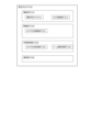
- the screen G1 is a diagram showing an example of a screen G1 displayed on the display unit 201.
- the screen G1 is an example of an operation screen.
- the screen G1 displayed on the display unit 201 displays, for example, a field map G10 showing a stadium F.
- drone icons G11a and G11b showing the photographing device 1000 photographing the stadium F here the first drone 100a and the second drone 100b, respectively, are displayed.
- a first shooting area field G12a showing the area photographed by the first drone 100a, and a second shooting area field G12b showing the area photographed by the second drone 100b are displayed superimposed on the field map G10.
- a first captured image field G40a and a second captured image field G40b showing the images photographed by the drone 100a and drone 100b, respectively, are displayed in association with the drone icons G11a and G11b.
- the blind spot area of the first drone 100a or the second drone 100b may be displayed on the field map G10.
- the user can easily identify the blind spot area A200 that is not captured, even when the stadium F is being captured by multiple cameras whose positions, shooting directions, and zoom amounts can be changed.
- the shooting position and shooting direction of the drones 100a and 100b may be controlled manually, or automatic tracking control of the ball or a specific player may be performed.
- automatic tracking control information about the ball or a specific player to be tracked may be displayed on the screen G1.
- the icons G11a, 11b representing the drones 100a, 100b display an arrow indicating the direction of travel of the drone 100.
- the direction of the nose of the drones 100a, 100b is not limited to the direction of travel of the drones 100a, 100b, and may be pointing in any direction.
- the direction of the nose of the drones 100a, 100b does not have to be constant while moving, and for example, the drones may move by yaw rotation while photographing players or the ball.
- the input control unit 220 shown in Fig. 9 accepts various inputs from a user such as a pilot.
- the input control unit 220 mainly accepts operations for an operation target device.
- the operation target device is, for example, any one of the drone 100, the mobile camera 710, and the fixed camera 720.
- the input control unit 220 accepts which operation target device is to be operated by an operation target switching unit 225 described later.
- the input control unit 220 of this embodiment mainly has the following functional units: a moving object position operation unit 221, a moving object attitude operation unit 222, a camera attitude operation unit 223, a camera zoom operation unit 224, an operation target switching unit 225, an automatic/manual switching unit 226, a target area selection unit 227, and a power input unit 229.
- the operation unit 221 for the moving body position includes an up-down movement input unit 221a and a left-right movement input unit 221b.
- the operation unit 222 for the moving body attitude includes a forward-backward movement input unit 222a and a yaw rotation input unit 222b.
- the up-down movement input unit 221a is an input unit for allowing the operator to move the target device up and down, and acquires input to the right input stick 327R. That is, when the right input stick 327R is moved upward (toward the back when held in the hand), the target device rises, and when the right input stick 327R is moved downward (toward the front when held in the hand), the target device descends.
- the left-right movement input unit 221b is an input unit for allowing the operator to move the target device left and right, and acquires input to the right input stick 327R. That is, when the right input stick 327R is moved to the right, the target device moves to the right, and when the right input stick 327R is moved to the left, the target device moves to the left.
- the forward/backward movement input unit 222a is an input unit for allowing the operator to move the target device forward/backward, and acquires input to the left input stick 327L. That is, when the left input stick 327L is moved upward (toward the rear when held in the hand), the target device moves forward, and when the left input stick 327L is moved downward (toward the front when held in the hand), the target device moves backward.
- the yaw rotation input unit 222b is an input unit for allowing the operator to yaw rotate the target device, and acquires input to the left input stick 327L. That is, when the left input stick 327L is moved to the right, the target device turns right, and when the left input stick 327L is moved to the left, the target device turns left.
- mobile camera 710 can only move by sliding on guide rail 7126, if mobile camera 710 is specified as the device to be operated and a movement operation is input in a direction in which movement is not possible, the operation may be invalidated. Also, fixed camera 720 cannot move, so if fixed camera 720 is specified as the device to be operated, the movement operation is invalidated.
- the camera attitude operation unit 223 is an input unit for operating the camera holding unit 142 via the imaging control unit 143 and for controlling the orientation of the imaging cameras 141, 7111, 7211 of the device to be operated.
- the camera attitude operation unit 223 obtains input to the right slider 326R.
- the camera attitude operation unit 223 accepts operation of either or both of the pitch angle and yaw angle of the imaging cameras 141, 7111, 7211.
- the camera zoom operation unit 224 is an input unit for operating the shooting magnification, i.e., the zoom amount, of the shooting cameras 141, 7111, and 7211, and obtains input to the left slider 326L.
- the operation target switching unit 225 is a functional unit that switches the operation target that transmits the command input to the control device 200.
- the operation target switching unit 225 determines the operation target to be either the drone 100, the mobile camera 710, or the fixed camera 720, for example, based on an appropriate signal input to the control device 200.
- the automatic/manual switching unit 226 is a functional unit that switches between automatic and manual control of the device to be operated.
- the controlled device switching unit 225 determines whether to operate automatically or manually, for example, based on an appropriate signal input to the control device 200.
- At least one of the controlled devices, the drone 100, the mobile camera 710, and the fixed camera 720, is capable of both automatic and manual control.
- the target area selection unit 227 is a functional unit that accepts input of the target area to be photographed by the photographing camera 141, 1711, or 1721.
- the target area selection unit 227 accepts input of a point on the stadium F.
- the target area selection unit 227 may accept input of the target area via a touch panel display that is configured integrally with the display unit 201 when at least a portion of an image or schematic diagram of the stadium F is displayed on the display unit 201.
- FIG. 13 is an example of a target area table T1 showing the correspondence between the identification numbers of multiple target areas set by subdividing the stadium F and the three-dimensional coordinates indicating the outer edge of each target area.
- the multiple target areas included in the target area table T1 may include areas of various sizes, or may include areas that overlap with each other.
- the target area selection unit 227 may accept a selection of a target area included in the target area table T1. Furthermore, when the target area selection unit 227 accepts the specification of an arbitrary position within the stadium F via the touch panel display, it may refer to the target area table T1 and identify the selected target area by extracting the target area to which the position belongs.
- the shooting mode setting unit 228 is a functional unit that sets the shooting mode of the shooting device 1000.
- the shooting modes include, for example, a tracking shooting mode and an overhead shooting mode.
- the tracking shooting mode is a shooting mode in which the ball is automatically tracked and photographed.
- the overhead shooting mode is a shooting mode in which the inside of the stadium F is photographed regardless of the position of the ball.
- the tracking shooting mode is a shooting mode in which the zoom amount is larger than that of the overhead shooting, for example, and the shooting is focused on the subject B.
- the overhead shooting mode may be a mode in which a wider shooting area is photographed than the tracking shooting mode.
- the shooting modes may also include other shooting modes such as a manual shooting mode and an automatic shooting mode.
- the power input unit 229 is a functional unit that accepts the power on/off command for the control device 200 via the power button 328.
- the input control unit 220 may be capable of receiving touch input to the display unit 201 and transmitting control commands to the drone 100 or the mobile camera 710 in response to the input. More specifically, for example, when the user selects appropriate information such as a map or schematic diagram displayed on the display unit 201, a route to the selected point may be automatically generated, causing the drone 100 or the mobile camera 710 to move autonomously.
- the communication unit 240 is a functional unit that transmits and receives signals between the control device 200 and an appropriate configuration included in the system 1.
- the control device 200 has a communication function that performs wireless communication with the drone 100 by wireless communication using Wi-Fi, 2.4 GHz, and 5.6 to 5.8 GHz frequency bands.
- the control device 200 also has a wireless communication function that can communicate with the server 300 via the communication network 400 using a communication standard such as LTE (Long Term Evolution).
- the communication unit 240 transmits various input signals by a user such as a pilot to the drone 100 or the server 300.
- the communication unit 240 also receives signals from the drone 100, the mobile camera 710, the fixed camera 720, the server 300, or the like.
- the server 300 manages or controls the movement and photography of the photographing devices 1000.
- the server 300 controls a plurality of photographing devices 1000, and after referring to the photographing range of a first photographing device 1000, determines the photographing mode of the other photographing devices 1000 so that the area not photographed by the first photographing device 1000 is supplemented by the other photographing devices 1000 and controls the other photographing devices 1000.
- the present system 1 determines the photographing mode of the second drone 100b by referring to the photographing range of the first drone 100a.
- the first and second photographing devices 1000 may be mobile cameras 710 or fixed cameras 720. That is, the present system 1 may determine the photographing mode of the mobile camera 710 or the fixed camera 720 by referring to the photographing range of the drone 100.
- the server 300 may determine the photographing mode of the drone 100, another mobile camera 710, or the fixed camera 720 by referring to the photographing range of the mobile camera 710.
- the server 300 may determine the photographing mode of the drone 100, the mobile camera 710, or the fixed camera 720 by referring to the photographing range of the fixed camera 720.
- the server 300 may be a general-purpose computer such as a workstation or personal computer, or may be logically realized by cloud computing.
- the server 300 is equipped with a calculation device such as a CPU for executing information processing, and storage devices such as RAM and ROM, which constitute the software configuration of the following main functional blocks: target area determination unit 310, camera information acquisition unit 320, blind spot area determination unit 330, photographed object position estimation unit 340, event detection unit 350, camera control command unit 360, communication unit 370, and memory unit 380.
- the server 300 also has an input/output unit (not shown) for inputting or outputting various types of information (image output, audio output).
- the target area determination unit 310 is a functional unit that determines the area that should be photographed by any one of the photographing cameras 141, 7111, and 7211, that is, the target area.
- the target area determination unit 310 mainly includes a target area information acquisition unit 311 and a target area recognition unit 312 .
- the target area information acquisition unit 311 receives information on the target area received, for example, via the target area selection unit 227 of the control device 200.
- the target area information acquisition unit 311 may also determine that the area that includes the subject B to be photographed is the target area.
- the target area recognition unit 312 is a functional unit that refers to the target area table T1 (see FIG. 13) and recognizes the three-dimensional coordinates of the accepted target area.
- the camera information acquisition unit 320 is a functional unit that acquires information related to the photographing camera 141 of the first drone 100a.
- the camera information acquisition unit 320 includes a camera position/attitude information acquisition unit 321, a photographed image acquisition unit 322, and a photographing mode acquisition unit 323.
- the camera position and orientation information acquisition unit 321 acquires information on the position and orientation of the shooting camera 141.
- the captured image acquisition unit 322 is a functional unit that acquires the captured image taken by the imaging camera 141.
- the shooting mode acquisition unit 323 is a functional unit that acquires the shooting mode set in the first drone 100a. In particular, the shooting mode acquisition unit 323 acquires whether or not the first drone 100a is in tracking shooting mode.
- the blind spot area determination unit 330 is a functional unit that determines a blind spot area A200 that is not photographed by the first photographing device 1000, out of the target area A110 to be photographed.
- the blind spot area determination unit 330 mainly includes a shooting area determination unit 331 , an outside-of-view-angle area determination unit 332 , and a shadow area determination unit 333 .
- FIG. 14 is a schematic diagram showing the first drone 100a taking pictures at the stadium F, and the shooting area A100a of the first drone 100a.
- the shooting area A100a is the area that is captured by the shooting camera 141 of the first drone 100a. In other words, the area included in the shooting area A100a is shown in the captured image G100a.
- the area of the stadium F that is not included in the shooting area A100a is not captured by the shooting camera 141.
- the area that is not included in the shooting area A100a is a first example of a blind spot area.
- the target area A110 indicates the range that is set as the area to be photographed.
- the target area A110 may be an area that is automatically determined by an appropriate functional unit of the present system 1, or may be an area specified by the user.
- the target area A110 is an area that includes the subject B to be photographed, and may be an area identified by image analysis of the photographed image.
- the subject B to be photographed is, for example, a ball, but is not limited to an object and may be a player, etc.
- the subject B to be photographed may be an object that is preset in the present system 1, or may be selected by the user.
- the subject B to be photographed may be something that moves within the stadium F.
- Area A200 of the target area A110 that is not included in the shooting area A100a cannot be photographed by the first drone 100a even though it requires shooting.
- this area A200 is defined as a blind spot area A200.
- Area A200 is a second example of a blind spot area. Because the blind spot area A200 cannot be photographed by the first drone 100a, shooting is performed by another drone 100b, a mobile camera 710, or a fixed camera 720 under the control of the system 1.
- the blind spot area A200 mainly includes an outside-of-view area A210 and a shadow area A220.
- the outside-of-view area A210 is an area that is not included in the angle of view of the shooting area A100.
- the shadow area A220 is an area that is included in the angle of view of the shooting area A100 but is hidden behind an obstruction P and is not photographed.
- An obstruction P is, for example, a group of players who are closely packed together. Note that the obstruction P may be a single player, or it may be any suitable object, such as an object, an animal such as a bird, fixed equipment, or various kinds of equipment used in sports such as a ball.
- the photographing area determination unit 331 extracts the photographing area A100a of the first drone 100a based on the information acquired by the camera information acquisition unit 320. For example, the photographing area determination unit 331 extracts the photographing area A100a based on the image captured by the photographing camera 141 of the first drone 100a.
- the shooting area determination unit 331 may also extract the shooting area A100 based on the position and direction of the camera and the zoom amount instead of or in addition to the information on the captured image. If the playing area for soccer or the like is a stadium F, the stadium F is approximately point-symmetric, so the shooting area cannot be uniquely identified based on the captured image information alone. In this regard, if the shooting area determination unit 331 is configured to extract the shooting area by referring to the information on the position and direction of the drone 100, the shooting area can be uniquely identified.
- the outside-of-view area determination unit 332 is a functional unit that identifies the outside-of-view area A210 that is not included in the angle of view of the shooting area A100.
- the outside-of-view area determination unit 332 determines the outside-of-view area based on information on the shooting area A100 determined by the shooting area determination unit 331 and information on the target area A110 to be photographed recognized by the target area recognition unit 312. In other words, the outside-of-view area determination unit 332 determines that an area of the target area A110 that is not included in the shooting area A100 is the outside-of-view area A210.
- the outside-of-angle-of-view area determination unit 332 may compare the shooting area A100 of all cameras 141, 1711, 1721 with each of the divided areas into which the court F100 is divided into a predetermined number of areas, in order to always keep the entire court F100 within the angle of view, and determine whether all of the divided areas are being shot by at least one of the cameras.
- the shadow area determination unit 333 is a functional unit that identifies shadow areas A220 that are included in the angle of view of the photographed area A100 but are hidden behind an obstruction and not photographed. For example, the shadow area determination unit 333 performs image analysis on the photographed image to identify the obstruction and determine the coordinates of the shadow area A220. The shadow area determination unit 333 determines that an area where multiple players are crowded together is a shadow area A220. The shadow area determination unit 333 may determine that one shadow area A220 is formed by multiple players. The shadow area determination unit 333 may also determine multiple shadow areas A220 simultaneously in one stadium F.
- the blind spot area determination unit 330 may predict the blind spot area A200 from the current time onward. For example, the blind spot area determination unit 330 predicts the shooting area A100a of the first drone 100a based on the moving direction and moving speed of the first drone 100a. In addition, instead of or in addition to predicting the shooting area A100a, the blind spot area determination unit 330 may predict the target area A110 from the current time onward based on the moving direction and moving speed of the target area A110 when the target area A110 moves based on the movement of the shooting target B or a predetermined setting.
- the blind spot area determination unit 330 predicts the position and range of the outside angle of view area A210 based on the prediction result of at least one of the shooting area A100a and the target area A110 from the current time onward. With this configuration, even if the shooting target B moves faster than the drone 100, it is possible to track and shoot more quickly.
- the blind spot area determination unit 330 may also predict the shadow area A220 from the current time onwards.
- the blind spot area determination unit 330 may estimate the type of obstruction that constitutes the shadow area A220, and estimate the direction and speed of movement of the shadow area A220 according to the type of obstruction.
- the blind spot area determination unit 330 predicts the position and range of the shadow area A220 after a predetermined time based on the position of the obstruction after a predetermined time and the position of the first drone 100a. With this configuration, the shadow area A220 of the first drone 100 can be reliably photographed by the second drone 100b.
- the photographing target position estimating unit 340 is a functional unit that estimates the position of a predetermined photographing target B set in the present system 1 .
- the photographed object position estimation unit 340 performs image analysis on the image captured by the photographing equipment 1000.
- the photographed object position estimation unit 340 also estimates the position of the photographed object B in the stadium F based on the position, direction, and zoom amount of the photographing equipment 1000 that captured the image in which the photographed object B appears, and the position of the photographed object B in the captured image.
- the position of the photographed object B may be expressed in two-dimensional coordinates or three-dimensional coordinates.
- the photographed object position estimation unit 340 may estimate the change in position of the photographed object B.
- the photographed object position estimation unit 340 may analyze a number of images captured at different times, and estimate the change in position of the photographed object B.
- the photographed object position estimation unit 340 may estimate the moving direction or moving speed of the photographed object B.
- the photographing subject position estimation unit 340 estimates the position of the subject B based on a past photographed image captured by the photographing device 1000.
- the photographing subject position estimation unit 340 refers to a past photographed image captured immediately before the subject B moves outside the photographed image, and estimates the moving direction of the subject B to estimate the current position of the subject B.
- the photographing subject position estimation unit 340 may also estimate the moving speed of the subject B in addition to the moving direction to estimate the current position of the subject B.
- the object position estimation unit 340 may estimate the position of the object B based on the image captured by the second drone 100b.
- the object position estimation unit 340 may also refer to the image captured by the second drone 100b at the time when the object B moves outside the shooting area A100a, or may refer to the image captured by the second drone 100b before the object B moves outside the shooting area A100a.
- the event detection unit 350 is a functional unit that detects an event that occurs in the stadium F.
- the event detection unit 350 detects an event, for example, by performing image analysis on the actions of the object B to be photographed, the players, the referee, and the like.
- the event detection unit 350 may detect that a long pass has been made when the ball B moves a predetermined distance or more at a predetermined speed or more during a match.
- a long pass is an action of handing the ball over to a player who is far away, and the ball moves a long distance at a relatively fast speed.
- a long pass is a pass in which the ball moves faster than the speed at which the drone 100a can track and photograph it.
- the camera control command unit 360 is a functional unit that transmits a control command to the photographing device 1000.
- the control command from the camera control command unit 360 is a command to control at least one of the position and direction of the photographing device 1000, and the position, direction, and zoom amount of the photographing cameras 141, 7111, and 7211 mounted on the photographing device 1000. That is, the camera control command unit 360 transmits a control command to control the position and direction of the photographing device 1000.
- the camera control command unit 360 transmits a control command to control the photographing direction and zoom amount of the photographing cameras 141, 7111, and 7211 mounted on the photographing device 1000.
- the camera control command unit 360 may transmit a control command to control the position of the photographing cameras 141, 7111, and 7211.
- the camera control command unit 360 controls the first drone 100a so that the specified target area A110 is included in the shooting area A100a.
- the camera control command unit 360 may refer to this and control the first drone 100a to the shooting position, shooting direction, or zoom amount according to the specified target area A110.
- the camera control command unit 360 may control the first drone 100a so that the subject B is included in the shooting area A100a of the first drone 100a.
- the camera control command unit 360 transmits a control command to the second drone 100b to cause the second drone 100b to capture an image of an area not captured by the first drone 100a. More specifically, the camera control command unit 360 controls the second drone 100b to capture an image of the blind spot area A200 of the first drone 100a extracted by the blind spot area determination unit 330.
- the capture area A100b of the second drone 100b may include the entire blind spot area A200, or may include at least a portion of the blind spot area A200.
- FIG. 15 is a schematic diagram showing how the second drone 100b photographs an area not photographed by the first drone 100a.
- the first drone 100a tracks and photographs the subject B, while the second drone 100b photographs the stadium F from above.
- the photographing area A100b of the second drone 100b includes at least a portion of the blind spot area A200.
- the multiple drones 100 can capture the entire game.
- the area around the object B such as a ball
- the formation of the players changes not only around the object B, so it is also necessary to capture the entire game.
- the first drone 100a tracks and captures the object B
- the position, shooting direction, and zoom amount of the first drone 100a change from moment to moment, resulting in a quick change in the shooting area A100a and a movement of the blind spot.
- the zoom amount is increased to capture the object B more fully, an even wider blind spot occurs. In other words, many blind spots occur with only the first drone 100a.
- the second drone 100b can supplement and capture the area around the first drone 100a, so it is possible to capture the area of interest where the object B is located and the movements of the players in the entire stadium F, and capture the entire game.
- the target area determination unit 310 recognizes the target area (step S101).
- the camera information acquisition unit 320 acquires information about the camera (step S102).
- the blind spot area determination unit 330 determines the blind spot area A200 (see Fig. 14) (step S103).
- the camera control command unit 360 controls the photographing unit 140 (step S104). Note that in step S104, the camera control command unit 360 may control at least one of the photographing unit 140, the mobile camera 710, and the fixed camera 720.
- the blind spot area A200 of the first drone 100a can be supplemented by the second drone 100b, allowing the entire competition to be filmed. This allows for precise and objective analysis when this footage is used for coaching or reflection on the competition. Furthermore, when this footage is used for spectator purposes, spectators can be made even more entertained by being able to watch every detail of the competition.
- the camera control command unit 360 may control multiple other cameras, including the second drone 100b, to capture the blind spot area A200 of the first drone 100a.
- Fig. 17 is a schematic diagram showing three or more drones 100 shooting one stadium F.
- the first drone 100a, the second drone 100b, the third drone 100c, and the fourth drone 100d are shooting the shooting areas A100a, A100b, A100c, and A100d, respectively, in the stadium F.
- At least three of the first drone 100a, the second drone 100b, the third drone 100c, and the fourth drone 100d are shooting by focusing on a local area, rather than shooting from an overhead angle.
- the camera control command unit 360 refers to the blind spot area A200 of the first drone 100a and controls the second drone 100b, the third drone 100c and the fourth drone 100d so that the blind spot area A200 is included in the shooting area A100b, A100c, A100d of any of the second drone 100b, the third drone 100c and the fourth drone 100d.
- FIG. 18 is an example of capturing an image of the shadow area A220 in the first drone 100a so as to be included in the shooting area A100b of the second drone 100b.
- a crowded area A300 occurs in the shooting area A100a of the first drone 100a.
- this crowded area A300 is an area where multiple players are crowded.
- the rear side of the crowded area A300 as seen from the first drone 100a is the shadow area A221.
- FIG. 18(c) is a schematic diagram showing the second drone 100b capturing an image of the shooting area A100b including the shadow area A221.
- the second drone 100b flies to a position opposite the first drone 100a in response to a command from the camera control command unit 360, and captures the crowded area A300 from the opposite side to the first drone 100a.
- the shadow area A221 can be captured without omission.
- the camera control command unit 360 may refer to the area of the shooting area A100a of the first drone 100a and control the second drone 100b so that the area of the shooting area A100b of the second drone 100b is larger than the shooting area A100a. With this configuration, there is a high probability that the second drone 100b can capture areas that are not included in the shooting area A100a, so the competition can be captured more thoroughly.
- the camera control command unit 360 may also refer to the shooting mode of the first drone 100a, and when the first drone 100a is in the tracking shooting mode and tracking and shooting a specified shooting object B, control the second drone 100b to take an overhead shot of an area wider than the shooting area A100 of the first drone 100a.
- the camera control command unit 360 may fly the first drone 100a and the second drone 100b facing each other along a pair of touchlines F111a, F111b or a pair of goal lines F110a, F110b of the stadium F, thereby complementing each other's blind spot areas and taking photographs.
- the camera control command unit 360 may cause one of the first drone 100a and the second drone 100b to fly along the touch line F111a or F111b, and the other to fly along the goal line F110a or F110b.
- Figure 19 is a schematic diagram showing two drones 100a and 100b facing each other and taking pictures.
- FIG. 19(a) shows the first drone 100a and the second drone 100b facing each other along a pair of touch lines F111a, F111b to take pictures.
- the shooting areas A100a, A100b of the first drone 100a and the second drone 100b extend beyond the center, and the shooting areas A100a, A100b overlap each other in the center.
- FIG. 19(b) shows the first drone 100a and the second drone 100b facing each other along a pair of goal lines F110a, F110b to take pictures. Even in this case, the shooting areas A100a, A100b of the first drone 100a and the second drone 100b extend beyond the center, and the shooting areas A100a, A100b overlap each other in the center.
- Figure 19(c) shows the first drone 100a and the second drone 100b facing each other and taking pictures in yet another manner.
- the first drone 100a and the second drone 100b fly in one side area and the other side area of the halfway line F150, respectively.
- the drone 100 takes pictures inside the court F100, and one of the shooting areas A100a, A100b extends to the rear of the other shooting areas A100b, A100a.
- the communication unit 370 has a modem or the like (not shown) and is capable of communicating with the photographing equipment 1000, the control device 200, and the like via the communication network 400.
- the storage unit 380 is a functional unit that stores data necessary for controlling a plurality of image capturing devices 1000 .
- the storage unit 380 includes a target area information storage unit 371.
- the target area information storage unit 371 stores a target area table T1 shown in FIG. 13.
- the target area table T1 is primarily referenced by the target area determination unit 310 and the outside-angle-of-view area determination unit 332 as appropriate.
- FIG. 20 is a flowchart showing the processing when the object to be photographed B moves outside the photographing area A100a of the first drone 100a.
- FIG. 21 is a schematic diagram showing an example of a situation in which the processing according to the flowchart is performed.
- the event detection unit 350 detects a long pass (Y in step S201).
- a long pass is made by a player on the court F100. Therefore, as shown in FIG. 21(b), the object to be photographed B deviates outside the photographing area A100a.
- the photographing subject position estimation unit 340 predicts the trajectory of ball B upon detection of the long pass (step S202).
- the camera control command unit 360 controls the first drone 100a so that the future position of ball B is included in the photographing area A100a according to the prediction result of the trajectory of ball B (step S203).
- the camera control command unit 360 also controls the second drone 100b to change the photographing area A100b so that the outside-angle-of-view area A210 of the first drone 100a is included in the photographing area A100b of the second drone 100b (step S204).
- the position, direction, or zoom amount of the second drone 100b is different from that before the long pass was detected.
- Figure 22 shows another example of the case where ball B moves outside the shooting area A100a of the first drone 100a.
- ball B quickly moves from the shooting area A100a of the first drone 100a to the lower right as indicated by the arrow in the figure, and deviates from the shooting area A100a.
- the moving speed of ball B is faster than the speed at which the first drone 100a can track and photograph it.
- the subject B deviates outside the angle of view.
- the second drone 100b photographs the court F100 from above, and the shooting area A100b encompasses almost the entire surface of the court F100. Therefore, the subject B is also captured in the image captured after the deviation as shown in Figure 21(c).
- the position of the photographed object B is estimated by the photographed object position estimation unit 340 based on the image of the photographed area A100b.
- the camera control command unit 360 controls the position, photographing direction, or zoom amount of the first drone 100a based on the position of the photographed object B.
- the photographed object B is again included in the photographed area A100a.
- FIG. 23 shows yet another example of a case where ball B moves outside the shooting area A100a of the first drone 100a.
- ball B quickly moves from the shooting area A100a of the first drone 100a to the lower right as indicated by the arrow in the figure, and deviates from the shooting area A100a.
- the moving speed of ball B is faster than the speed at which the first drone 100a can track and photograph it.
- the subject B deviates outside the angle of view.
- ball B also deviates from the shooting area A100b of the second drone 100b, as shown in FIG. 23(c).
- the position of the photographed object B is estimated by the photographed object position estimation unit 340 based on past images of the photographed area A100b.
- the camera control command unit 360 controls the position, photographing direction, or zoom amount for at least one of the first drone 100a and the second drone 100b based on the estimated position of the photographed object B.
- the photographed object B is again included in the photographed area A100a.
- the camera control command unit 360 may control the position of the drone 100 based on the remaining battery power of the drone 100, and may switch the drone 100 photographing the stadium F by having another drone 100b supplement and photograph the photographing area A100a of the drone 100a with low battery power.
- FIG. 24 is a flowchart showing an example of a process for switching drones 100 when the remaining battery power decreases.
- FIG. 25 and FIG. 26 are schematic diagrams showing the state of the stadium F when switching drones 100.
- the process of switching the drone 100 shown in FIG. 24 can also be applied when an abnormal or broken state of the drone 100 or the photographing camera 141 is detected, other than when the drone is switched due to a drop in the remaining battery level.
- the abnormal state means a reversible temporary abnormal state, and includes, for example, a state in which the temperature of the equipment mounted on the drone 100 rises above a predetermined value, a state in which the lens of the photographing camera 141 becomes cloudy or dirty, and a state in which an abnormality occurs in the rotation speed of the propellers 122 of the drone 100 (such as a state in which only one propeller has a higher rotation speed than the other propellers).
- a broken state means a state in which an irreversible problem has occurred, such as a failure of various sensors such as a geomagnetic sensor or a state in which vibrations of an abnormal strength are occurring in the aircraft. Even if it is detected that the drone or camera has become broken, if the failure mode or degree of failure is such that there is no risk of an immediate crash, it is desirable not to immediately start a landing operation, but to wait until the arrival of the third drone 100c before switching to photographing.
- the camera control command unit 360 measures the remaining battery charge of the first drone 100a photographing the stadium F using an appropriate method, and determines whether the remaining battery charge is equal to or lower than a predetermined value (step S301). If the remaining battery charge is equal to or lower than the predetermined value, the camera control command unit 360 moves the third drone 100c to the position of the first drone 100a (step S302). If the third drone 100c photographs approximately the same area as the photographing area A100a of the first drone 100a (Y in step S303), the third drone 100c stops moving toward the position of the first drone 100a (step S304). Next, the first drone 100a retreats outside the court F100 (step S305).
- step S303 may be made that the same area is being photographed when the photographed areas A100a and A100b are completely identical, or when areas that overlap by a certain amount or more are being photographed.
- the third drone 100c may enter the court F100 at an altitude higher than the shooting altitude of the first drone 100a, and then lower its altitude near the first drone 100a. With this configuration, the third drone 100c moves within the court F100 at a sufficiently high altitude, so it does not interfere with the game and can also be prevented from entering the shooting range of the first drone 100a.
- step S305 as shown in FIG. 26, the first drone 100a flies the shortest distance toward the outer edge of the court F100, then passes outside the court F100 and moves to a predetermined landing point.
- the drone can retreat to the outside of the court F100 in the shortest time possible, without interfering with the game and ensuring safety within the court F100.
- the first drone 100a may also retreat outside the court F100 so as not to enter the shooting area A100b of the third drone 100c. That is, for example, the camera control command unit 360 generates a flight route that detours around the shooting area A100b and exits the court F100.
- the detour route may be, for example, a route in which the first drone 100a passes through a higher flight altitude than the third drone 100c. That is, the first drone 100a and the third drone 100c fly so that their altitudes are switched at positions adjacent to each other in the court F100. That is, the second drone 100b is lowered and the first drone 100a is raised.
- the first drone 100a may also move to the outer edge of the court F100 by the shortest distance after retreating a predetermined distance in the opposite direction to the shooting direction of the third drone 100c. Even with this configuration, the first drone 100a can be evacuated outside the court F100 by bypassing the shooting area A100b of the third drone 100c.
- the third drone 100c photographs the target area A110, so the above-described configuration ensures that the third drone 100c photographs the target area A110 appropriately.
- the first drone 100a retreats after the third drone 100c completes the shooting area A100a of the first drone 100a, so that the target area A110 can be reliably photographed.
- the drone 100 capturing images is changed when the remaining battery power of the drone 100a decreases.
- the change of the drone 100 may be triggered by other events.
- the change may be triggered by a minor abnormality in the drone 100a, or the change may be triggered by an event in which the drone 100a is replaced by a drone 100 having different functions depending on the scene.
- the blind spot area A200 of the first drone 100a can be supplemented by the second drone 100b, so that it is possible to capture both the area of interest where the subject B is located and the movements of the athletes in the entire stadium F, and capture every corner of the competition. Furthermore, when this video is used for coaching or reflection on the competition, precise and objective analysis is possible. Also, when this video is used for spectator purposes, spectators can enjoy the competition even more by being able to watch every corner of the competition.
- the present invention is not limited to the above embodiment, and various configurations can be adopted based on the contents of this specification.
- the series of processes described in relation to the above embodiment may be implemented using software, hardware, or a combination of software and hardware.
- a computer program for implementing each function of the server 300 according to this embodiment may be created and implemented in a PC or the like.
- a computer-readable recording medium on which such a computer program is stored may also be provided. Examples of the recording medium include a magnetic disk, an optical disk, a magneto-optical disk, and a flash memory.
- the above computer program may also be distributed, for example, via the communication network 400, without using a recording medium.
Landscapes
- Engineering & Computer Science (AREA)
- Multimedia (AREA)
- Signal Processing (AREA)
- Mechanical Engineering (AREA)
- Remote Sensing (AREA)
- Aviation & Aerospace Engineering (AREA)
- Microelectronics & Electronic Packaging (AREA)
- Studio Devices (AREA)
Abstract
Description
本発明は、撮影システム、撮影方法および撮影プログラムに関する。 The present invention relates to a photography system, a photography method, and a photography program.
特許文献1には、複数のドローンを同時に飛行させて撮影対象物を撮影する技術が開示されている。
スポーツ等をより見やすく撮影するために、任意の位置、方向又はズーム量で撮影を行う技術が必要とされている。特に、広い競技エリアで行われるサッカー等の競技を撮影する場合には、競技エリア全体が画角に入るズームアウト撮影ではなく、撮影方向とズーム量を調整することにより、ある程度フォーカスしたズーム量で撮影を行うことで、ボール周辺等の局所的なプレーをより見やすく撮影することが求められる。また、競技エリアの様々な位置で同時並行に繰り広げられる複数のプレーをもれなく撮影する必要もある。 In order to film sports and other events in a way that makes them easier to see, there is a need for technology that allows filming at any position, direction, or zoom level. In particular, when filming sports such as soccer, which are played over a wide playing area, it is necessary to film localized plays, such as those around the ball, more clearly by adjusting the filming direction and zoom level and filming with a somewhat focused zoom level, rather than zooming out so that the entire playing area fits into the field of view. There is also a need to film all of the multiple plays that are taking place simultaneously in various positions on the playing area.
この点、特許文献1記載のシステムでは、競技エリアにおいて撮影できていない箇所、いわゆる死角が発生するため、撮影対象フィールドで発生する事象の様子をもれなく撮影することができなかった。
In this regard, the system described in
本発明は上記のような課題を考慮してなされたものであり、撮影対象フィールドで発生する事象をもれなく撮影できる撮影システムを提供することを目的とする。 The present invention was made in consideration of the above problems, and aims to provide a photography system that can capture all events that occur in the field being photographed.
上記目的を達成するため、本発明の一の観点に係る撮影システムは、所定の移動エリアを移動する複数の移動体と、複数の前記移動体にそれぞれ搭載され、撮影対象フィールドの少なくとも一部を撮影する第1のカメラおよび第2のカメラと、前記第1のカメラにより撮影される撮影エリアに基づいて、前記第1のカメラで撮影されていない死角エリアを前記第2のカメラで撮影するように前記第2のカメラを制御するカメラ制御指令部と、を備える。 In order to achieve the above object, a photography system according to one aspect of the present invention comprises a plurality of moving objects that move within a predetermined moving area, a first camera and a second camera that are mounted on each of the plurality of moving objects and capture at least a portion of a field to be photographed, and a camera control command unit that controls the second camera based on the photographing area photographed by the first camera so that the second camera photographs a blind spot area not photographed by the first camera.
前記カメラ制御指令部は、前記第2のカメラの、位置、方向およびズーム量の少なくともいずれかを制御するものとしてもよい。 The camera control command unit may control at least one of the position, direction, and zoom amount of the second camera.
前記第1のカメラによる前記撮影エリアに基づいて、前記第1のカメラの画角外である画角外エリアと、前記画角内の陰エリアの少なくともいずれかを前記死角エリアとして判定する死角エリア判定部をさらに備え、前記カメラ制御指令部は、前記死角エリアを前記第2のカメラで撮影するように前記第2のカメラを制御するものとしてもよい。 The system may further include a blind spot area determination unit that determines, based on the area captured by the first camera, at least one of an area outside the field of view of the first camera and a shadow area within the field of view as the blind spot area, and the camera control command unit may control the second camera to capture the blind spot area with the second camera.
前記第1のカメラにより撮影された画像に基づいて、前記第1のカメラによる前記撮影エリアを判定する撮影エリア判定部をさらに備えるものとしてもよい。 The system may further include a photographing area determination unit that determines the photographing area of the first camera based on an image photographed by the first camera.
前記撮影対象フィールドにおいて撮影すべきエリアである対象エリアを判定する対象エリア判定部をさらに備え、前記死角エリア判定部は、前記第1のカメラの位置又は撮影方向と、前記対象エリアとに基づいて、前記死角エリアを判定するものとしてもよい。 The system may further include a target area determination unit that determines a target area, which is an area to be photographed in the photographing field, and the blind spot area determination unit may determine the blind spot area based on the position or photographing direction of the first camera and the target area.
前記対象エリア又は前記第1のカメラが移動する場合に、前記死角エリア判定部は、現時点以降の前記死角エリアを予測し、前記カメラ制御指令部は、予測された前記死角エリアに基づいて前記第2のカメラを制御するものとしてもよい。 When the target area or the first camera moves, the blind spot area determination unit may predict the blind spot area from the current time onwards, and the camera control command unit may control the second camera based on the predicted blind spot area.
前記撮影エリアおよび前記死角エリアの少なくともいずれかを操作画面に表示する表示制御部をさらに備えるものとしてもよい。 The system may further include a display control unit that displays at least one of the shooting area and the blind spot area on the operation screen.
前記第1のカメラおよび前記第2のカメラは、ドローン又は地上に載置された機器に搭載されているあるいはワイヤーに固定され前記ワイヤーを引き上げ又は引き下げることで移動可能であるものとしてもよい。 The first camera and the second camera may be mounted on a drone or a device placed on the ground, or may be fixed to a wire and be movable by pulling up or down the wire.
前記カメラ制御指令部は、前記死角エリアを、前記第2のカメラを含む他の複数のカメラで撮影するように、前記他の複数のカメラを制御するものとしてもよい。 The camera control command unit may control the other cameras, including the second camera, to capture the blind spot area.
前記カメラ制御指令部は、前記第1のカメラが所定の撮影対象物を追跡撮影している場合に、前記第1のカメラの撮影エリアよりも広い範囲を俯瞰撮影するように、前記第2のカメラを制御するものとしてもよい。 The camera control command unit may control the second camera to capture an overhead image of a range wider than the image capture area of the first camera when the first camera is tracking and capturing an image of a specific object.
前記第1のカメラおよび前記第2のカメラは、それぞれ第1のドローンおよび第2のドローンに搭載されており、前記撮影対象フィールドには、1対のタッチラインと1対のゴールラインで囲まれる矩形のコートがあらかじめ定義されており、前記カメラ制御指令部は、前記撮影対象フィールド両側の1対のタッチライン、又は1対のゴールライン、又は前記タッチラインと前記ゴールラインに沿って前記第1のドローンおよび前記2のドローンを飛行させて撮影することで、互いの前記死角エリアを補完して撮影するものとしてもよい。 The first camera and the second camera are mounted on a first drone and a second drone, respectively, and the field to be photographed is a predefined rectangular court surrounded by a pair of touchlines and a pair of goal lines, and the camera control command unit may fly the first drone and the second drone along a pair of touchlines on both sides of the field to be photographed, or a pair of goal lines, or the touchlines and the goal lines, to photograph by complementing each other's blind spot areas.
前記第1のカメラおよび前記第2のカメラは、それぞれ第1のドローンおよび第2のドローンに搭載されており、前記撮影対象フィールドには、1対のタッチラインと1対のゴールラインで囲まれる矩形のコートと、前記一対のタッチラインの中点間を接続するハーフウェーラインがあらかじめ定義されており、前記カメラ制御指令部は、前記コート内であって前記ハーフウェーラインにより分割される第1エリアと第2エリアにそれぞれ前記第1のドローンおよび前記第2のドローンを互いに向かい合って飛行させて撮影することで、互いの前記死角エリアを補完して撮影するものとしてもよい。 The first camera and the second camera are mounted on a first drone and a second drone, respectively, and the field to be photographed has a rectangular court surrounded by a pair of touchlines and a pair of goal lines, and a halfway line connecting the midpoints of the pair of touchlines defined in advance, and the camera control command unit may fly the first drone and the second drone facing each other to photograph a first area and a second area within the court divided by the halfway line, thereby complementing each other's blind spot areas and photographing them.
撮影対象物の位置を推定する撮影対象物位置推定部をさらに備え、前記撮影対象物位置推定部は、前記撮影対象物が前記第1のカメラの前記撮影エリア外に移動した場合に、前記第2のカメラの撮影画像に基づいて前記撮影対象物の位置を推定し、前記カメラ制御指令部は、前記撮影対象物が前記第1のカメラの前記撮影エリアに含まれるように前記第1のカメラを制御するものとしてもよい。 The camera may further include a subject position estimation unit that estimates the position of a subject to be photographed, and when the subject to be photographed moves outside the photographing area of the first camera, the subject position estimation unit estimates the position of the subject to be photographed based on an image captured by the second camera, and the camera control command unit may control the first camera so that the subject to be photographed is included in the photographing area of the first camera.
撮影対象物の位置を推定する撮影対象物位置推定部をさらに備え、前記撮影対象物位置推定部は、前記撮影対象物が前記第1のカメラの前記撮影エリア外に移動した場合に、前記第1のカメラ又は前記第2のカメラの過去の撮影画像に基づいて前記撮影対象物の位置を推定し、前記カメラ制御指令部は、前記撮影対象物が前記第1のカメラ又は前記第2のカメラの前記撮影エリアに含まれるように、前記第1のカメラおよび前記第2のカメラの少なくともいずれかを制御するものとしてもよい。 The camera may further include a subject position estimation unit that estimates the position of a subject to be photographed, and when the subject to be photographed moves outside the photographing area of the first camera, the subject position estimation unit estimates the position of the subject to be photographed based on a past image captured by the first camera or the second camera, and the camera control command unit may control at least one of the first camera and the second camera so that the subject to be photographed is included in the photographing area of the first camera or the second camera.
前記第1のカメラは、第1のドローンに搭載されており、前記カメラ制御指令部は、前記第1のドローンのバッテリ残量が所定値以下になった場合、あるいは前記第1のドローン又は前記第1のカメラの異常又は故障を検知した場合に、第3のカメラを搭載する第3のドローンを前記第1のドローンの位置に移動させ、前記第3のドローンが前記第1のドローンの撮影エリアと同一エリアを撮影した場合に、前記第1のドローンを退避させるものとしてもよい。 The first camera may be mounted on a first drone, and the camera control command unit may move a third drone equipped with a third camera to the position of the first drone when the remaining battery charge of the first drone falls below a predetermined value, or when an abnormality or malfunction of the first drone or the first camera is detected, and may cause the first drone to retreat when the third drone photographs the same area as the photographing area of the first drone.
上記目的を達成するため、本発明の別の観点に係る撮影方法は、所定の移動エリアを移動する複数の移動体と、複数の前記移動体にそれぞれ搭載され、撮影対象フィールドの少なくとも一部を撮影する第1のカメラおよび第2のカメラと、を有するシステムが、前記第1のカメラにより撮影される撮影エリアに基づいて、前記第1のカメラで撮影されていない死角エリアを前記第2のカメラで撮影するように前記第2のカメラを制御するカメラ制御指令ステップ、を実行する。 In order to achieve the above object, a photographing method according to another aspect of the present invention is a system having a plurality of moving objects moving in a predetermined moving area, and a first camera and a second camera mounted on each of the plurality of moving objects and photographing at least a part of a field to be photographed, the system executing a camera control command step for controlling the second camera to photograph a blind spot area not photographed by the first camera based on the photographing area photographed by the first camera.
上記目的を達成するため、本発明のさらに別の観点に係る撮影プログラムは、所定の移動エリアを移動する複数の移動体と、複数の前記移動体にそれぞれ搭載され、撮影対象フィールドの少なくとも一部を撮影する第1のカメラおよび第2のカメラと、を有するシステムに対し、前記第1のカメラにより撮影される撮影エリアに基づいて、前記第1のカメラで撮影されていない死角エリアを前記第2のカメラで撮影するように前記第2のカメラを制御するカメラ制御指令ステップ、を実行させる。 In order to achieve the above object, a photography program according to yet another aspect of the present invention causes a system having a plurality of moving objects moving within a predetermined moving area, and a first camera and a second camera mounted on each of the plurality of moving objects and photographing at least a portion of a field to be photographed, to execute a camera control command step for controlling the second camera to photograph a blind spot area not photographed by the first camera based on the photographing area photographed by the first camera.
なお、コンピュータプログラムは、各種のデータ読取可能な記録媒体に格納して提供したり、インターネット等のネットワークを介してダウンロード可能に提供したりすることができる。 In addition, computer programs can be provided by being stored on various data-readable recording media, or by being made available for download via a network such as the Internet.
本発明によれば、競技をもれなく撮影することができる。 The present invention makes it possible to capture the entire competition.
以下では、添付図面を参照しながら、本発明の好適な実施形態について詳細に説明する。本明細書及び図面において、実質的に同一の機能構成を有する構成要素については、同一の符号を付することにより重複説明を省略する。また、以下に示す実施形態は、例を表すに過ぎず、その用途、目的又は規模等に応じて、他の既知の要素や代替手段を採用可能である。 Below, a preferred embodiment of the present invention will be described in detail with reference to the attached drawings. In this specification and drawings, components having substantially the same functional configuration will be denoted with the same reference numerals to avoid repetitive explanation. Furthermore, the embodiments shown below are merely examples, and other known elements or alternative means may be adopted depending on the application, purpose, scale, etc.
<A.一実施形態>
[A-1.構成]
(A-1-1.全体構成)
図1は、本発明の一実施形態に係る撮影システム1(以下「システム1」ともいう。)の全体構成図である。システム1は、競技場F(図11)(撮影対象フィールドの例である。)で行われている競技、又は催物会場で行われている催物等をドローン100(移動体の例である。)で撮影するものである。撮影対象フィールドは、ドローン100による撮影対象となる2次元のエリアを指す。また、ドローン100は、撮影対象フィールドを撮影するために、飛行エリアを飛行する。飛行エリアは、例えば撮影対象フィールドおよびその周辺、ならびにそれらの上空を含む。ドローン100は、1個のシステム1に複数含まれており、システム1は、1個の競技場Fに複数のドローン100a、100bを同時に飛行させることで当該競技場Fを撮影することができる。ドローン100又はドローン100に搭載される後述する撮影用カメラ141(図2参照)は、特許請求の範囲におけるカメラの一例である。
A. One embodiment
[A-1. Configuration]
(A-1-1. Overall composition)
FIG. 1 is an overall configuration diagram of a photography system 1 (hereinafter also referred to as "
また、システム1は、撮影対象フィールドを撮影する移動式カメラ710又は固定式カメラ720を含んでいてもよい。移動式カメラ710および固定式カメラ720は、それぞれ特許請求の範囲におけるカメラの別の例である。本説明において、「撮影用カメラ」とは、ドローン100の撮影用カメラ141、移動式カメラ710が備える撮影用カメラ7111又は固定式カメラ720が備える撮影用カメラ7211のいずれかを指すものとする。
The
以降の説明においては、必要に応じてサッカーを撮影するシステム1を例に説明するが、本システム1はサッカー以外の競技や催物にも適用可能である。
In the following explanation, we will use as an example the
図1に示すように、システム1は、ドローン100に加えて、主として、操縦者がドローン100を操作するための操縦装置200と、ドローン100の飛行及び撮影を管理するサーバ300と、外部入力装置600と、外部システム700と、移動式カメラ710と、固定式カメラ720と、を有する。
As shown in FIG. 1, in addition to the
ドローン100と操縦装置200は、無線通信(基地局800を介するものを含み得る。)を介して互いに接続される。操縦装置200とサーバ300は、インターネット回線等の通信ネットワーク400を介して互いに接続される。ドローン100は、自己位置の特定等のため、人工衛星500から衛星信号を取得する。
The
外部入力装置600は、操縦装置200とは別に本システム1との間で情報を送受信できる装置であり、例えばスマートホン又はタブレット端末等のモバイル端末で構成される。外部入力装置600は、例えば、競技場Fで行われている競技の監督、コーチ、ベンチの選手、審判、又はコート設備関係者等により操作可能である。外部入力装置600は、例えば、緊急の撮影中断指令を受け付ける機能を有し、当該撮影中断指令に基づいてドローン100は緊急避難を行う。また、外部入力装置600は、ドローン100の飛行モードの切替入力を受け付けてもよい。さらに、外部入力装置600は表示装置を備え、操縦装置200の表示部201と同様の情報が表示されてもよい。特に、外部入力装置600は、競技で発生するイベント情報を取得してもよい。当該イベント情報は、外部入力装置600のユーザにより、ドローン100の飛行モードを切り替える入力を行う際に参照される。
The
外部システム700は、システム1とは別途に構成される任意のシステムであってよく、例えば、競技場Fで行われる競技に関して配備されるシステムとして、コート設備システム、試合運営システム、審判支援システム、といったシステムが適用可能である他、競技とは独立して配備されている気象観測システム又は地震観測システムといったシステムが適用可能である。複数の外部システム700がシステム1に接続されていてもよい。システム1は、種々の外部システム700から、緊急の撮影中断指令やドローン100の飛行モードの切替指令を受け付けてもよい。また、種々の外部システム700は、競技で発生するイベント情報を取得してもよい。
The
外部システム700の1例としてのコート設備システムは、例えばシステム1から撮影画像の輝度を取得し、競技場Fの照明の照度調整又は明滅を制御してもよい。また、コート設備システムは、システム1から照明照度の要求を受信して照度調整又は明滅を制御してもよい。
The court facilities system, which is an example of the
また、移動式カメラ710および固定式カメラ720は、撮影対象フィールドを撮影するカメラであり、ドローン100と同様にシステム1の各構成と通信可能になっている。
Moveable camera 710 and fixed
ドローン100、移動式カメラ710および固定式カメラ720は、いずれも競技場Fの所定エリアを撮影するための撮影機器1000の例である。以降の説明において、ドローン100、移動式カメラ710又は固定式カメラ720を総称して「撮影機器1000」と呼ぶことがある。システム1に含まれる撮影機器1000の個数は複数であればよく、2個以上の任意の数である。撮影機器1000は、ドローン100、移動式カメラ710および固定式カメラ720のうち1種類又は2種類であってもよい。また、同種の撮影機器1000が複数あってもよい。なお、ドローン100は、撮影位置、方向および高度を比較的自由に制御可能であるため、競技場Fの対象エリアをもれなく撮影するにあたっては、撮影機器1000の少なくとも1個はドローン100であると好適である。
The
システム1の構成は、図1に示すものに限らず、例えばインターネット回線等の通信ネットワーク400を介して、ドローン100と操縦装置200とサーバ300と基地局800とがそれぞれ相互に通信可能に接続されていてもよい。この場合、ドローン100は操縦装置200を介さずにLTE等の通信方法によって直接通信ネットワーク400と無線通信を行ってよい。そのため、ドローン100と操縦装置200及び基地局800は、直接無線通信を行う必要がなく、遠隔地においてそれぞれ通信ネットワーク400に接続できればよい。そのため、ドローン100と操縦装置200が遠隔地に存在する場合(例えば、操縦者が遠隔操作を行う場合等)に適したシステム構成である。
The configuration of
また、システム1は、インターネット回線等の通信ネットワーク400を介して、ドローン100と操縦装置200と基地局800とサーバ300とがそれぞれ相互に通信可能に接続され、且つドローン100及び基地局800は人工衛星500を介した衛星通信により通信ネットワーク400と通信接続されてもよい。
In addition, in the
さらに、システム1は、1台のドローン100に対して複数のサーバ300が複数の通信ネットワーク400を介して接続され、すなわちシステムが冗長化されていてもよい。この場合、サーバ300、又は通信ネットワーク400に異常が生じた場合であっても、冗長化された他のサーバ300や通信ネットワーク400によりシステム1の動作、ひいてはドローン100による撮影を継続することができるため、システム1の信頼性を向上させることができる。なお、上記の2形態においても、ドローン100と操縦装置200が遠隔にあっても操縦可能であるため、遠隔操作に適した構成ではあるが、これに限られず、操縦者がドローン100を見ながら手動制御する有視界飛行にも適用可能である。
Furthermore, in the
上記実施形態において説明した装置は、単独の装置として実現されてもよく、一部又は全部が通信ネットワーク400で接続された複数の装置(例えばドローン100、操縦装置200、クラウドサーバ300)等により実現されてもよい。例えば、サーバ300の各機能部及び記憶部は、互いに通信ネットワーク400で接続された異なるサーバ300、ドローン100、操縦装置200に実装されることにより実現されてもよい。
The device described in the above embodiment may be realized as a single device, or may be realized by multiple devices (e.g.,
(A-1-2.ドローン100)
(A-1-2-1.ドローン100の概要)
図2は、本実施形態のドローン100を簡略的に示す外観斜視図である。図3は、本実施形態のドローン100の機能構成図である。上記の通り、ドローン100は、競技場F(図11)で行われている競技、催物会場で行われている催物等を撮影する。
(A-1-2. Drone 100)
(A-1-2-1. Overview of Drone 100)
Fig. 2 is a simplified external perspective view of the
本明細書において、「ドローン」とは、動力手段(電力、原動機等)、操縦方式(無線であるか有線であるか、及び、完全自律飛行型であるか部分手動操縦型であるか等)を問わず、また、有人か無人かを問わず、自律的に姿勢制御を行う機能を有する飛行体全般を指すこととする。また、ドローンは、無人航空機(Unmanned Aerial Vehicle:UAV)、飛行体、マルチコプター(Multi Copter)、RPAS(Remote Piloted Aircraft Systems)、又はUAS(Unmanned Aircraft Systems)等と称呼されることがある。 In this specification, "drone" refers to any flying object that has the ability to autonomously control its attitude, regardless of the power source (electricity, prime mover, etc.), control method (wireless or wired, and fully autonomous or partially manual, etc.), and whether manned or unmanned. Drones are also sometimes referred to as Unmanned Aerial Vehicles (UAVs), flying objects, multicopters, RPAS (Remote Piloted Aircraft Systems), or UAS (Unmanned Aircraft Systems), etc.
図2に示すように、ドローン100の外観は主として、筐体101と、複数のプロペラ122と、により構成される。筐体101は例えば略直方体であるが、形状は任意である。筐体101の左右側面には、側方に伸び出る棒状の連結部102が連結されている。連結部102の他端には、それぞれプロペラ122と、各プロペラ122を回転させるモータ121が連結される。モータ121は、例えば電動モータである。なお、本実施形態においては、連結部102、プロペラ122およびモータ121は4個ずつ備えられているが、個数はこれに限られない。プロペラ122は単独のプロペラで構成されていてもよいし、同軸配置された複数のプロペラで構成されていてもよい。各プロペラの羽根(ブレード)の枚数及び形状は特に限定されない。
As shown in FIG. 2, the exterior of the
また、プロペラ122の外側には、障害物に対するプロペラの干渉を防ぐためのプロペラガード(図示せず)を設けてもよい。
In addition, a propeller guard (not shown) may be provided on the outside of the
筐体101には、例えば撮影用カメラ141が、筐体101下方にカメラ保持部142により保持されている。また、筐体101の前方面には、障害物検知カメラ131が配設されている。障害物検知カメラ131は、本実施形態においては対をなす2個のカメラにより構成される、いわゆるデュアルカメラである。障害物検知カメラ131は、ドローン100の前方を撮像するように配設されている。なお、障害物検知カメラ131は、前方面だけではなく筐体101のすべての面、例えば略直方体の筐体101においては6面に設けられていてもよい。
In the
ドローン100は、ドローン100の周囲にいる人々に対して、ドローン100の存在について注意喚起を行う警報装置250を備える。警報装置250は、例えば警告灯251及びスピーカ252を有する。警告灯251は、プロペラ122又はモータ121毎に設けられ、例えば複数のモータ121の各側面に配設される。警告灯251は正面の他、あらゆる方向から視認できるようモータ121の円筒状の側面に沿って配設されてよい。スピーカ242は、警告音を出力するものであり、ドローン100の筐体101に設けられる。スピーカ242は、例えば筐体101下面に設けられ、警告音をドローン100の下方に向かって伝達させる。
The
(A-1-2-2.ドローン100の機能ブロック)
図3に示すように、ドローン100は、情報処理を実行するためのCPU(Central Processing Unit)等の演算装置、RAM(Random Access Memory)及びROM(Read Only Memory)等の記憶装置を備え、これにより、主として、測定部110、飛行機能部120,障害物検知部130、撮影部140および通信部150の各機能ブロックを有する。
(A-1-2-2. Functional blocks of drone 100)
As shown in FIG. 3, the
測定部110は、ドローン100又はその周辺に関する情報を測定する機能部である。測定部110は、例えば位置測定部111、方位測定部112、高度測定部113および速度測定部114等を有する。測定部110はこれらに加えて、温度、気圧、風速、加速度等の情報を取得する種々のセンサ等を含んでもよい。
The measurement unit 110 is a functional unit that measures information related to the
位置測定部111は、人工衛星500からの信号を受信し、それに基づいて機体の位置(絶対位置)を測定する。位置測定部111は、特に限定されないが、例えば、GNSS(Global Navigation Satellite System)、GPS(Global Positioning System)等を用いて、現時点での自己位置を測定する。自己位置の測定方法として、例えば、RTK-GNSS(Real Time Kinematic - Global Navigation Satellite System)を用いることもできる。位置情報は、少なくとも平面視での2次元での座標情報(例えば緯度、経度)を含み、好ましくは高度情報を含む3次元での座標情報を含む。
The position measurement unit 111 receives signals from the
また、RTK等の相対測位に用いる固定局の基準点の情報を提供する基地局800がドローン100及び操縦装置200と無線通信可能に接続されることで、ドローン100の位置をより高い精度で計測することが可能となる。ここで、VRS(Virtual Reference Station)による仮想基準点方式を用いたRTK計測を行う場合には、基地局800を省略すること、又は、基地局800又はドローン100の位置座標推定の精度をさらに向上することができる。
In addition, the
方位測定部112は、機体の向き(機首方向、ヘディング方向)を測定する。方位測定部112は、例えば地磁気の測定によりドローン100の機体の機首方位(ヘディング方向)を測定する地磁気センサ、コンパス等で構成される。
The orientation measurement unit 112 measures the orientation of the aircraft (nose direction, heading direction). The orientation measurement unit 112 is composed of a geomagnetic sensor that measures the nose direction (heading direction) of the
高度測定部113は、ドローン100下方(鉛直下向き)の地面に対する距離としての対地高度(以下「飛行高度」ともいう。)を測定する。 The altitude measurement unit 113 measures the altitude above the ground (hereinafter also referred to as "flight altitude") as the distance from the ground below the drone 100 (vertically downward).
速度測定部114は、ドローン100の飛行速度を検出する。速度測定部114は、例えばジャイロセンサ等公知のセンサにより速度を測定してよい。
The speed measurement unit 114 detects the flight speed of the
(A-1-2-3.飛行機能部120)
飛行機能部120は、ドローン100を飛行させる機構および機能部であり、ドローン100を浮上させて、所望の方向に移動するための推力を機体に発生させる。図2及び図3に示すように、飛行機能部120は、複数のモータ121と、複数のプロペラ122と、飛行制御部123と、を有する。
(A-1-2-3. Flight function section 120)
The flight function unit 120 is a mechanism and function unit that causes the
飛行制御部123は、複数のモータ121を独立して制御することにより各プロペラ122を回転させ、ドローン100に浮上、前進、旋回、着陸等の各動作を行わせ、離陸から飛行中、着陸までのドローン100の姿勢角制御及び飛行動作を制御する。
The flight control unit 123 independently controls the
飛行制御部123は、フライトコントローラとも呼ばれる処理ユニットを有する。処理ユニットは、プログラマブルプロセッサ(例えば、中央処理ユニット(CPU)、MPU又はDSP)等の1つ以上のプロセッサを有することができる。処理ユニットは、メモリ(記憶部)にアクセス可能である。メモリは、1つ以上のステップを行うために処理ユニットが実行可能であるロジック、コード、及び/又はプログラム命令を記憶している。メモリは、例えば、SDカードやRAM等の分離可能な媒体又は外部の記憶装置を含んでいてもよい。測定部110により取得される各種データ、又は撮影用カメラ141で撮影した動画もしくは静止画のデータは、当該メモリに直接に伝達され且つ記憶されてもよい。なお、各データは外部メモリに記録することもできる。
The flight control unit 123 has a processing unit, also called a flight controller. The processing unit may have one or more processors, such as a programmable processor (e.g., a central processing unit (CPU), MPU, or DSP). The processing unit has access to a memory (storage unit). The memory stores logic, code, and/or program instructions that the processing unit can execute to perform one or more steps. The memory may include, for example, a separable medium such as an SD card or RAM, or an external storage device. Various data acquired by the measurement unit 110, or video or still image data captured by the
処理ユニットは、ドローン100の機体の状態を制御するように構成された制御モジュールを含んでいる。例えば、制御モジュールは、6自由度(並進運動x、y及びz、並びに回転運動θx、θy及びθz)を有するドローン100の空間的配置、姿勢角角度、角速度、角加速度、角速度及び/又は加速度を調整するためにドローン100の飛行機能部120(推力発生部)を制御する。
The processing unit includes a control module configured to control the state of the
飛行制御部123は、操縦装置200からの操縦信号に基づいて、又は予め設定された自律飛行プログラムに基づいて、ドローン100の飛行を制御することができる。また飛行制御部123は、撮影対象フィールド、飛行許可/禁止エリア、これに対応する飛行ジオフェンスの情報、2次元又は3次元の地図データを含む地図情報、ドローン100の現在の位置情報、姿勢情報(機首方位情報)、速度情報、及び加速度情報等の各種情報及びこれらの任意の組み合わせに基づいてモータ121を制御することにより、ドローン100の飛行を制御することができる。
The flight control unit 123 can control the flight of the
●撮影対象フィールドの例
本明細書において、「撮影対象フィールド」は、撮影対象となる2次元の場所(例えば、競技場F)を意味する。
Example of a Field to be Shootinged In this specification, the term "field to be shot" refers to a two-dimensional location to be shot (for example, the stadium F).
図11は、ドローンが飛行する撮影対象フィールドの例である競技場Fの1例を示す模式図であり、同図は競技場Fを上から見た図である。競技場Fは、例えば直線状の外縁により区画される略矩形のコートF100と、コートF100の外縁を覆う所定の領域であるコート外領域F200により構成される。コートF100の外縁は、互いに向かい合うゴールラインF110a、F110bと、互いに向かい合うタッチラインF111a、F111bと、が略直角にそれぞれ接続されることにより構成される。ゴールラインF110a、F110bとタッチラインF111a、F111bの接続点は、コーナーF112a、F113a、F112b、F113bとなっている。 FIG. 11 is a schematic diagram showing an example of a playing field F, which is an example of a field to be photographed by a drone, viewed from above. The playing field F is composed of a court F100 that is roughly rectangular and is defined by, for example, a straight outer edge, and an outer court area F200 that is a predetermined area that covers the outer edge of the court F100. The outer edge of the court F100 is composed of mutually opposing goal lines F110a, F110b and mutually opposing touch lines F111a, F111b that are connected at roughly right angles. The connection points of the goal lines F110a, F110b and the touch lines F111a, F111b are the corners F112a, F113a, F112b, F113b.
1対のゴールラインF110a、F110bの略中央にはそれぞれゴールF120a、F120bが設けられている。コートF100の内部であってゴールF120a、F120bに連続する所定領域にはそれぞれペナルティエリアF130a、F130bが規定され、当該ペナルティエリアの外縁にはペナルティラインF140a、F140bが描画されている。 Goals F120a, F120b are provided approximately in the center of the pair of goal lines F110a, F110b. Penalty areas F130a, F130b are defined in specific areas inside the court F100 adjacent to the goals F120a, F120b, and penalty lines F140a, F140b are drawn on the outer edges of the penalty areas.
コートF100の中央には、1対のタッチラインの中点間を接続することでコートF100を略等分するハーフウェーラインF150が描画されている。ハーフウェーラインF150は、ゴールラインF110a、F110bと略平行である。 A halfway line F150 is drawn in the center of the court F100, connecting the midpoints of a pair of touchlines and dividing the court F100 into approximately equal parts. The halfway line F150 is approximately parallel to the goal lines F110a and F110b.
なお、ゴールラインF110a、F110b、タッチラインF111a、F111b、ペナルティラインF140a、F140bおよびハーフウェーラインF150は、競技者が競技を行うためにルール上必要な線であるため、いずれの線も視認できる態様で描画されることが一般的であるが、本発明の技術的範囲はこれに限られない。また、本説明においてはサッカーの競技場を例に説明するが、本発明にかかるシステムにより撮影される競技はサッカーに限られず、テニス等任意のあらゆる競技を含む。さらに、撮影対象はスポーツに限られず、その他の催物(コンサート、式典等)にも適用することが可能である。 Note that the goal lines F110a, F110b, touchlines F111a, F111b, penalty lines F140a, F140b, and halfway line F150 are required by the rules for players to play the game, and therefore all of these lines are generally drawn in a manner that allows them to be seen, but the technical scope of the present invention is not limited to this. Also, in this explanation, a soccer stadium is used as an example, but the sports that are photographed by the system of the present invention are not limited to soccer, and include any type of sports, such as tennis. Furthermore, the subject of the photography is not limited to sports, and the system can also be applied to other events (concerts, ceremonies, etc.).
コート外領域F200には、ドローン100又はシステム1の異常や故障を検知した場合に、ドローン100を退避させる退避地点H200が設定されている。ここにいう異常とは、ドローン100の空中移動の安定性に関する異常である。当該異常は、例えば、ドローン100の動作制御(挙動制御、撮影制御等)に伴う演算負荷が負荷閾値を上回る場合を含む。或いは、当該異常は、環境に関する一過性の異常、例えば強風等の影響によりドローン100の挙動制御値(例えば速度)の測定値が許容値を超えている場合を含んでもよい。
In the outside court area F200, an evacuation point H200 is set to which the
退避地点H200は、本実施形態においてはタッチラインF111aの外側に、タッチラインF111aに沿って設定されている。退避地点H200は複数あってよく、本実施例においては、3個である。退避地点H220は、ハーフウェーラインF150の延長線上付近に設定されている。退避地点H210、H230は、撮影位置L206、L211よりもゴールF120a、F120b寄りに設定されている。退避地点H200では、例えばドローン100の機体の交代やドローン100に搭載されているバッテリの交換が行われる。
In this embodiment, the evacuation point H200 is set outside the touchline F111a and along the touchline F111a. There may be multiple evacuation points H200, and in this embodiment, there are three. The evacuation point H220 is set near an extension of the halfway line F150. The evacuation points H210 and H230 are set closer to the goals F120a and F120b than the shooting positions L206 and L211. At the evacuation point H200, for example, the
(A-1-2-4.障害物検知部130)
図3の説明に戻る。障害物検知部130は、ドローン100の周辺の障害物を検知する機能部である。障害物は、例えば人、選手、物、鳥等の動物、固定設備およびボールを含んでよい。障害物検知部130は、取得画像に基づいてドローン100の下方等に位置する障害物の位置、速度ベクトル等を測定する。
(A-1-2-4. Obstacle detection unit 130)
Returning to the description of Fig. 3, the obstacle detection unit 130 is a functional unit that detects obstacles around the
障害物検知部130は、例えば障害物検知カメラ131、ToF(Time of Flight)センサ132およびレーザーセンサ133を有する。ToFセンサ132は、センサからパルス投光されたレーザがセンサ内の受光素子に戻ってくるまでの時間を計測し、その時間を距離に換算することで物体までの距離を測定する。レーザーセンサ133は、例えばLiDAR(Light Detection And Ranging)方式により、近赤外光や可視光、紫外線等の光線を対象物に光を照射し、その反射光を光センサでとらえ距離を測定する。
The obstacle detection unit 130 includes, for example, an
図2には、本実施形態では障害物検知カメラ131が前方を向いて配置されていることが図示されているが、このカメラ131、ToFセンサ132、およびレーザーセンサ133の種類、位置および数は任意であり、カメラ131に代えてToFセンサ132又はレーザーセンサ133が配置されていてもよいし、ToFセンサ132又はレーザーセンサ133が筐体101の6面、すなわち前面、背面、上面、底面、および両側面のすべてに設けられていてもよい。
In this embodiment, FIG. 2 shows that the
(A-1-2-5.撮影部140)
撮影部140は、競技場F(図11)における競技、又は催物会場における催物等の映像を撮影する機能部であり、撮影用カメラ141、カメラ保持部142及び撮影制御部143を有する。図2に示すように、撮影用カメラ141(撮像装置)は、ドローン100の本体の下部に配置され、ドローン100の周辺を撮影した周辺画像に関する画像データを出力する。撮影用カメラ141は、動画を撮影するビデオカメラ(カラーカメラ)である。動画には、図示しないマイクロホンで取得した音声データを含めてもよい。これに加えて又はこれに代えて、撮影用カメラ141は、静止画の撮影を行うものとすることも可能である。
(A-1-2-5. Photographing unit 140)
The photographing unit 140 is a functional unit that photographs images of a competition in the stadium F (FIG. 11) or an event in an event venue, and has a photographing
撮影用カメラ141は、カメラ保持部142に組み込まれた図示しないカメラアクチュエータにより向き(ドローン100の筐体101に対する撮影用カメラ141の姿勢)を調整可能である。撮影用カメラ141は、露出、コントラスト又はISO等のパラメータの自動制御機能を有していてもよい。カメラ保持部142は、機体の揺れ又は振動が撮影用カメラ141に伝わるのを抑制する、いわゆるジンバル制御の機構を有していてもよい。撮影制御部143は、撮影用カメラ141およびカメラ保持部142を制御し撮影用カメラ141の向き、撮影倍率(ズーム量)およびカメラの撮影条件等を調整する。撮影用カメラ141が取得した画像データは、ドローン100自体の記憶部、操縦装置200、サーバ300等にデータを送信することができる。
The orientation of the photographic camera 141 (the attitude of the
(A-1-2-6.通信部150)
通信部150は、通信ネットワーク400を介しての電波通信が可能であり、例えば、電波通信モジュールを含む。通信部150は、通信ネットワーク400(無線基地局800を含む。)を介することで、操縦装置200等との通信が可能である。
(A-1-2-6. Communication unit 150)
Communication unit 150 is capable of radio wave communication via
(A-1-3.移動式カメラ710)
(A-1-3-1.移動式カメラ710の概要)
図4は、本実施形態の移動式カメラ710を簡略的に示す外観斜視図である。図5は、本実施形態の移動式カメラ710の機能構成図である。移動式カメラ710は、地上に載置され、所定の経路を移動可能な機器であり、例えば陸上走行式カメラである。図4に示すように、移動式カメラ710は、ハードウェア構成として、主として、撮影用カメラ7111と、カメラ保持部7124と、摺動部7125と、案内レール7126と、を備えている。
(A-1-3. Mobile Camera 710)
(A-1-3-1. Overview of the mobile camera 710)
Fig. 4 is a simplified external perspective view of the mobile camera 710 of this embodiment. Fig. 5 is a functional configuration diagram of the mobile camera 710 of this embodiment. The mobile camera 710 is a device that is placed on the ground and can move along a predetermined route, such as a land-based camera. As shown in Fig. 4, the mobile camera 710 mainly includes, as its hardware configuration, a
撮影用カメラ7111は、撮影機能を実現する具体的構成であり、レンズおよび絞り等を備えている。撮影用カメラ7111は、可視光カメラであり、主に動画を撮影可能なカメラであるが、静止画を撮影できてもよいし、可視光以外の周波数領域の動画又は静止画が撮影可能であってもよい。
The photographing
カメラ保持部7124は、摺動部7125と撮影用カメラ7111とを連結し、撮影用カメラ7111を保持する機構である。カメラ保持部7124は、例えば摺動部7125の上方に撮影用カメラ7111を保持する。カメラ保持部7124は、略鉛直方向に回転軸を備え、撮影用カメラ7111を回動させることにより、撮影用カメラ7111の向きをヨー方向に変更可能である。なお、カメラ保持部7124は、ピッチ方向、すなわち撮影用カメラ7111が上方又は下方に向くようにも回動可能であってよい。
The
摺動部7125は、上面にカメラ保持部7124が連結される筐体である。摺動部7125は、案内レール7126と篏合し、案内レール7126に対して摺動する。摺動の具体的態様として、例えば、摺動部7125の内部に図示しない車輪が案内レール7126に当接して配設され、この車輪を後述するカメラ位置調整部7123により電気的に駆動することで摺動部7125を移動させてよい。また、カメラ位置調整部7123により駆動される機構は、摺動部7125に配設される構成に代えて、案内レール7126に備えられていてもよい。
The sliding
案内レール7126は、摺動部7125と篏合する長尺状の部材である。案内レール7126は、地面等の接地面に載置される。摺動部7125は、案内レール7126に沿って摺動する。すなわち、撮影用カメラ7111およびその撮影範囲は、摺動部7125および案内レール7126により、案内レール7126に沿って移動可能になっている。
The
また、図5に示すように、移動式カメラ710は、移動式カメラ710が備えるCPU、ROMおよびRAM等の適宜の構成により、ソフトウェア構成として、主として撮影部7110、駆動部7120、状態取得部7130および通信部7140の各機能ブロックを構成する。
As shown in FIG. 5, the mobile camera 710 is configured with appropriate components such as a CPU, ROM, and RAM provided in the mobile camera 710, and is configured as software to mainly include functional blocks of an
撮影部7110は、撮影対象を撮影する機能部である。撮影部7110は、カメラ制御部7112を介して撮影用カメラ7111を制御し、対象エリアを撮影する。カメラ制御部7112は、撮影用カメラ7111の撮影有無の他、例えば撮影用カメラ7111のズーム量やF値等の撮影用カメラ7111の内部に設定される撮影条件を制御する。
The photographing
駆動部7120は、撮影用カメラ7111の位置を制御する機能部である。駆動部7120は、主として、カメラ方位調整部7121、およびカメラ位置調整部7123を備える。
The driving unit 7120 is a functional unit that controls the position of the
カメラ方位調整部7121は、カメラ保持部7124を制御することで、撮影用カメラ7111の向きを調整する機能部である。カメラ方位調整部7121は、撮影用カメラ7111の向きのうち、ヨー方向およびピッチ方向のいずれか又は両方を制御する。
The camera orientation adjustment unit 7121 is a functional unit that adjusts the orientation of the
カメラ位置調整部7123は、摺動部2125を制御することで、撮影用カメラ7111の位置を調整する機能部である。カメラ位置調整部7123は、案内レール2126の位置に沿って撮影用カメラ7111の位置を変更する。なお、案内レール2126が湾曲して配置されている場合には、カメラ位置調整部7123により撮影用カメラ7111の向きが調整されてもよい。
The camera position adjustment unit 7123 is a functional unit that adjusts the position of the photographing
状態取得部7130は、移動式カメラ710の状態を取得する機能部である。状態取得部7130は、主として、カメラ方位取得部7131、ズーム量取得部7132、およびカメラ位置取得部7133を備える。 The status acquisition unit 7130 is a functional unit that acquires the status of the mobile camera 710. The status acquisition unit 7130 mainly includes a camera orientation acquisition unit 7131, a zoom amount acquisition unit 7132, and a camera position acquisition unit 7133.
カメラ方位取得部7131は、撮影用カメラ7111の向きを取得する機能部である。カメラ方位取得部7131は、例えば撮影用カメラ7111に搭載されている適宜のセンサを参照し、撮影用カメラ7111の向きを取得する。また、カメラ方位取得部7131は、駆動部7120による回動量又は移動量を参照し、撮影用カメラ7111の向きを推定してもよい。カメラ方位取得部7131は、撮影用カメラ7111の位置を参照し、当該位置における案内レール7126の配設方向に基づいて撮影用カメラ7111の向きを推定してもよい。
The camera orientation acquisition unit 7131 is a functional unit that acquires the orientation of the photographing
ズーム量取得部7132は、撮影用カメラ7111のズーム量を取得する機能部である。ズーム量取得部7132は、カメラ制御部7112により設定された撮影用カメラ7111のズーム量を取得してもよい。また、ズーム量取得部7132は、撮影用カメラ7111の設定値を参照してもよい。
The zoom amount acquisition unit 7132 is a functional unit that acquires the zoom amount of the photographing
カメラ位置取得部7133は、撮影用カメラ7111の位置を取得する機能部である。カメラ位置取得部7133は、例えば撮影用カメラ7111に搭載されているGNSS等の適宜のセンサを参照し、撮影用カメラ7111の位置を取得する。また、カメラ方位取得部7131は、駆動部7120による撮影用カメラ7111の移動量を参照し、撮影用カメラ7111の向きを推定してもよい。
The camera position acquisition unit 7133 is a functional unit that acquires the position of the photographing
通信部7140は、例えば操縦装置200および基地局800と通信を行い、情報を送受信する機能部である。通信部7140は、例えば撮影用カメラ7111の位置、方位又はズーム量の設定値を操縦装置200から受信する。また、通信部7140は、撮影用カメラ7111の位置、方位又はズーム量の実際の値を、操縦装置200に送信する。
The communication unit 7140 is a functional unit that communicates with, for example, the
なお、移動式カメラ710の態様は上述に限られず、制御により撮影用カメラの位置又は方位を変更可能な適宜の態様が採用できる。例えば、撮影用カメラがワイヤーに固定され、当該ワイヤーを引き上げ又は引き下げることにより撮影用カメラを移動させる態様であってもよい。例えば撮影用カメラは、撮影用カメラの上方であって互いに異なる位置に支持される複数のワイヤーにより支持され、各ワイヤーの長さを調整することで、撮影用カメラの位置および方位を制御できるようになっている。 The configuration of the mobile camera 710 is not limited to the above, and any suitable configuration can be adopted that allows the position or orientation of the photographic camera to be changed by control. For example, the photographic camera may be fixed to a wire, and the photographic camera may be moved by pulling up or down the wire. For example, the photographic camera may be supported by multiple wires that are supported at different positions above the photographic camera, and the position and orientation of the photographic camera can be controlled by adjusting the length of each wire.
(A-1-4.固定式カメラ720)
(A-1-4-1.固定式カメラ720の概要)
図6は、本実施形態の固定式カメラ720を簡略的に示す外観斜視図である。図7は、本実施形態の固定式カメラ720の機能構成図である。固定式カメラ720は、地上又は所定の固定設備に配設される機器であり、位置は固定されている一方、撮影方向は変更可能になっていてもよい。図6に示すように、固定式カメラ720は、ハードウェア構成として、主として、撮影用カメラ7211と、カメラ保持部7224と、を備えている。
(A-1-4. Fixed Camera 720)
(A-1-4-1. Overview of the fixed camera 720)
Fig. 6 is a simplified external perspective view of the fixed
撮影用カメラ7211は、撮影機能を実現する具体的構成であり、レンズおよび絞り等を備えている。撮影用カメラ7211は、移動式カメラ710に搭載されている撮影用カメラ7111と同様の構成であってよい。
The photographing
カメラ保持部7224は、競技場Fの所定地点と撮影用カメラ7211とを連結し、撮影用カメラ7211を保持する機構である。カメラ保持部7224は、移動式カメラ710に搭載されているカメラ保持部7124と同様の構成であってよい。すなわち、カメラ保持部7224は、撮影用カメラ7211の向きをヨー方向およびピッチ方向の少なくともいずれかに回動可能である。
The
また、図7に示すように、固定式カメラ720は、固定式カメラ720が備えるCPU、ROMおよびRAM等の適宜の構成により、ソフトウェア構成として、主として撮影部7210、駆動部7220、状態取得部7230および通信部7240の各機能ブロックを構成する。
As shown in FIG. 7, the fixed
固定式カメラ720の各構成について、移動式カメラ710が備える各構成と同一名称の構成は、それぞれ同様の機能を備える構成である。すなわち、撮影部7210は、撮影部7110と同様の構成である。駆動部7220は、カメラ方位駆動部7221を備える。カメラ方位駆動部7221は、移動式カメラ710が備えるカメラ方位調整部7121と同様の機能を有し、撮影用カメラ7211の向きを調整する。状態取得部7230は、カメラ方位取得部7231およびズーム量取得部7232を備える。カメラ方位取得部7231およびズーム量取得部7232は、移動式カメラ710が備えるカメラ方位取得部7131およびズーム量取得部7132とそれぞれ同様の構成であり、撮影用カメラ7211の向きおよびズーム量を取得する。通信部7240は、通信部7140と同様の構成である。
The components of the fixed
(A-1-5.操縦装置200)
(A-1-5-1.操縦装置200の概要)
図8は、本実施形態の操縦装置200を簡略的に示す外観正面図である。図9は、本実施形態の操縦装置200の機能構成図である。操縦装置200は、操縦者の操作によりドローン100を制御すると共に、ドローン100から受信した情報(例えば、位置、高度、電池残量、カメラ映像等)を表示する携帯情報端末である。なお、本実施形態では、ドローン100の飛行状態(高度、姿勢等)は、操縦装置200が遠隔制御可能であってもよいし、ドローン100が自律的に制御してもよい。例えば、操縦装置200を介して操縦者からドローン100に飛行指令が送信されると、ドローン100は自律飛行を行う。また、離陸や帰還等の基本操作時、及び緊急時にはマニュアル操作が行なえるようになっていてもよい。
(A-1-5. Control device 200)
(A-1-5-1. Overview of the control device 200)
FIG. 8 is a front view of the exterior of the
図8に示すように、操縦装置200は、ハードウェア構成として、表示部201および入力部202を備える。表示部201および入力部202は、互いに有線又は無線で通信可能に接続されている。表示部201は、操縦装置200に一体に組み込まれたタッチパネル又は液晶モニタ等で構成されていてもよいし、操縦装置200に有線接続又は無線接続された液晶モニタ、タブレット端末、スマートホン等の表示装置で構成されていてもよい。ハードウェア構成としての表示部201には、タッチ等の入力を受け付ける素子が一体的に組み込まれ、タッチパネルディスプレイとなっていてもよい。
As shown in FIG. 8, the
入力部202は、操縦者がドローン100を操縦する際に飛行方向や離陸/着陸等の動作指令を入力する機構である。
図8(a)に示すように、入力部202は、左スライダ326L、右スライダ326R、左入力スティック327L、右入力スティック327R、電源ボタン328及び帰還ボタン329を有する。左スライダ326Lおよび右スライダ326Rは、例えば0/1の入力、又は1次元の無段階もしくは段階的な情報の入力を受け付ける操作子であり、操縦者は例えば操縦装置200を手で保持した状態で、左右の人差し指によりスライドさせて入力を行う。左入力スティック327Lおよび右入力スティック327Rは、複数次元の無段階又は段階的な情報の入力を受け付ける操作子であり、例えばいわゆるジョイスティックである。また、左入力スティック327Lおよび右入力スティック327Rは、押下による0/1の入力を受け付けてもよい。電源ボタン328及び帰還ボタン329は、押下を受け付ける操作子であり、機械式スイッチ等により構成される。
The
As shown in FIG. 8A, the
左入力スティック327Lおよび右入力スティック327Rは、例えば、離陸、着陸、上昇、下降、右旋回、左旋回、前進、後進、左移動、および右移動等を含めた3次元のドローン100の飛行動作を指示する入力操作を受け付ける。図8(b)は、図8(a)に示す左入力スティック327Lおよび右入力スティック327Rの各入力に対応させて、ドローン100の移動方向又は旋回方向を示した模式図である。なお、この対応関係は例示である。
The left input stick 327L and the
図9に示すように、操縦装置200は、情報処理を実行するためのCPU等の演算装置、RAM及びROM等の記憶装置を備え、これによりソフトウェア構成として、主として表示制御部210、入力制御部220および通信部240の各機能ブロックを構成する。
As shown in FIG. 9, the
(A-1-5-2.表示制御部210)
表示制御部210は、ドローン100又はサーバ300から取得したドローン100のステータス情報等を操縦者に表示する。表示制御部210は、撮影対象フィールド、飛行許可/禁止エリア、飛行ジオフェンス、地図情報、ドローン100の現在の位置情報、姿勢情報(方向情報)、速度情報、加速度情報及びバッテリ残量等の各種情報に関する画像を表示することができる。ここにいう「現在の位置情報」は、ドローン100の現在位置の水平方向位置の情報(すなわち緯度及び経度)を含んでいればよく、高度情報(絶対高度又は相対高度)は含まなくてもよい。
(A-1-5-2. Display control unit 210)
The
表示制御部210は、カメラ状態表示部211と、撮影エリア表示部212と、を有する。
The
カメラ状態表示部211は、撮影機器1000が有する各カメラ141、7111、7211の状態を表示部201に表示する機能部である。各カメラ141、7111、7211の状態とは、例えば各カメラ141、7111、7211の状態の位置、方向又はズーム量であってよい。
The camera status display unit 211 is a functional unit that displays the status of each
撮影エリア表示部212は、撮影機器1000が有する各カメラ141、7111、7211により撮影される撮影エリアA100を、表示部201に表示させる機能部である。
The photographing area display unit 212 is a functional unit that displays the photographing area A100 photographed by each
●表示部201の表示例
図12は、表示部201に表示される画面G1の1例を示す図である。画面G1は、操作画面の1例である。同図に示すように、表示部201に表示される画面G1には、例えば、競技場Fを示すフィールドマップG10が表示される。また、フィールドマップG10上およびその周辺には、競技場Fを撮影する撮影機器1000、ここでは第1ドローン100aおよび第2ドローン100bをそれぞれ示すドローンアイコンG11a、G11bが表示されている。
12 is a diagram showing an example of a screen G1 displayed on the
フィールドマップG10上には、第1ドローン100aによる撮影エリアを示す第1撮影エリア欄G12a、および第2ドローン100bによる撮影エリアを示す第2撮影エリア欄G12bが、それぞれフィールドマップG10に重畳して表示されている。フィールドマップG10の周辺には、ドローン100aおよびドローン100bがそれぞれ撮影する撮影画像を表示する第1撮影画像欄G40a、および第2撮影画像欄G40bが、ドローンアイコンG11a、G11bに対応付けて表示されている。
On the field map G10, a first shooting area field G12a showing the area photographed by the
フィールドマップG10上には、撮影エリアを示す欄に代えて、又は加えて、第1ドローン100a又は第2ドローン100bの死角エリアを表示してもよい。このような構成によれば、ユーザは、位置、撮影方向およびズーム量が変更されえる複数のカメラで競技場Fを撮影している場合においても、撮影できていない死角エリアA200を容易に把握できる。
In place of or in addition to the column showing the shooting area, the blind spot area of the
なお、ドローン100a、100bの撮影位置と撮影方向の制御は、手動であってもよいし、ボール又は特定の選手への自動追跡制御が行われてもよい。自動追跡制御が行われている場合には、追跡対象となるボール又は特定の選手の情報を画面G1上に表示するものとしてもよい。
The shooting position and shooting direction of the
ドローン100a、100bを示すアイコンG11a、11bには、ドローン100の進行方向を示す矢印が表示されている。なお、ドローン100a、100bの機首方向は、ドローン100a、100bの進行方向とは限らず、任意の方向を向いていてよい。移動中においてドローン100a、100bの機首方向は一定でなくてもよく、例えばヨー回転により選手又はボールを撮影しながら移動してもよい。
The icons G11a, 11b representing the
(A-1-5-3.入力制御部220)
図9に示す入力制御部220は、操縦者等のユーザによる各種の入力を受け付ける。入力制御部220は、主として、操作対象機器に対する操作を受け付ける。操作対象機器は、例えばドローン100、移動式カメラ710および固定式カメラ720のいずれかである。入力制御部220は、いずれの操作対象機器を操作対象とするかを、後述する操作対象切替部225により受け付ける。
(A-1-5-3. Input control unit 220)
The
本実施形態の入力制御部220は、主として、移動体位置の操作部221、移動体姿勢の操作部222、カメラ姿勢の操作部223、カメラズームの操作部224、操作対象切替部225、自動・手動切替部226、対象エリア選択部227、および電源入力部229の各機能部を有する。
The
移動体位置の操作部221は、上下移動入力部221aおよび左右移動入力部221bを備える。移動体姿勢の操作部222は、前後移動入力部222aおよびヨー旋回入力部222bを備える。 The operation unit 221 for the moving body position includes an up-down movement input unit 221a and a left-right movement input unit 221b. The operation unit 222 for the moving body attitude includes a forward-backward movement input unit 222a and a yaw rotation input unit 222b.
上下移動入力部221aは、操縦者により操作対象機器を上下移動させるための入力部であり、右入力スティック327Rへの入力を取得する。すなわち、右入力スティック327Rが上側(手に保持した状態において奥側)に移動されると操作対象機器が上昇し、右入力スティック327Rが下側(手に保持した状態において手前側)に移動されると操作対象機器が下降する。左右移動入力部221bは、操縦者により操作対象機器を左右移動させるための入力部であり、右入力スティック327Rへの入力を取得する。すなわち、右入力スティック327Rが右側に移動されると操作対象機器が右移動し、右入力スティック327Rが左側に移動されると操作対象機器が左移動する。
The up-down movement input unit 221a is an input unit for allowing the operator to move the target device up and down, and acquires input to the
前後移動入力部222aは、操縦者により操作対象機器を前後移動させるための入力部であり、左入力スティック327Lへの入力を取得する。すなわち、左入力スティック327Lが上側(手に保持した状態において奥側)に移動されると操作対象機器が前進し、左入力スティック327Lが下側(手に保持した状態において手前側)に移動されると操作対象機器が後進する。ヨー旋回入力部222bは、操縦者により操作対象機器をヨー旋回させるための入力部であり、左入力スティック327Lへの入力を取得する。すなわち、左入力スティック327Lが右側に移動されると操作対象機器が右旋回し、左入力スティック327Lが左側に移動されると操作対象機器が左旋回する。 The forward/backward movement input unit 222a is an input unit for allowing the operator to move the target device forward/backward, and acquires input to the left input stick 327L. That is, when the left input stick 327L is moved upward (toward the rear when held in the hand), the target device moves forward, and when the left input stick 327L is moved downward (toward the front when held in the hand), the target device moves backward. The yaw rotation input unit 222b is an input unit for allowing the operator to yaw rotate the target device, and acquires input to the left input stick 327L. That is, when the left input stick 327L is moved to the right, the target device turns right, and when the left input stick 327L is moved to the left, the target device turns left.
なお、移動式カメラ710は、案内レール7126上を摺動する移動しかできないため、移動式カメラ710が操作対象機器に指定されている場合において移動が不可能な方向への移動操作が入力された場合には、操作を無効化するものとしてもよい。また、固定式カメラ720は移動ができないため、固定式カメラ720が操作対象機器に指定されている場合においては、移動操作は無効化される。
Because mobile camera 710 can only move by sliding on
カメラ姿勢の操作部223は、撮影制御部143を介してカメラ保持部142を動作させ、操作対象機器の撮影用カメラ141、7111、7211の向きを操作するための入力部である。カメラ姿勢の操作部223は、右スライダ326Rへの入力を取得する。カメラ姿勢の操作部223は、撮影用カメラ141、7111、7211のピッチ角およびヨー角のいずれか又は両方の操作を受け付ける。
The camera attitude operation unit 223 is an input unit for operating the
カメラズームの操作部224は、撮影用カメラ141、7111、7211の撮影倍率、すなわちズーム量を操作するための入力部であり、左スライダ326Lへの入力を取得する。
The camera zoom operation unit 224 is an input unit for operating the shooting magnification, i.e., the zoom amount, of the
操作対象切替部225は、操縦装置200に入力される命令を送信する操作対象を切り替える機能部である。操作対象切替部225は、例えば操縦装置200に入力される適宜の信号に基づいて、操作対象をドローン100、移動式カメラ710および固定式カメラ720のいずれかに決定する。
The operation target switching unit 225 is a functional unit that switches the operation target that transmits the command input to the
自動・手動切替部226は、操作対象機器の自動操縦および手動操縦を切り替える機能部である。操作対象切替部225は、例えば操縦装置200に入力される適宜の信号に基づいて、自動操縦および手動操縦を決定する。操作対象機器であるドローン100、移動式カメラ710および固定式カメラ720の少なくともいずれかは、自動操縦および手動操縦の双方が可能である。
The automatic/manual switching unit 226 is a functional unit that switches between automatic and manual control of the device to be operated. The controlled device switching unit 225 determines whether to operate automatically or manually, for example, based on an appropriate signal input to the
対象エリア選択部227は、撮影用カメラ141、1711又は1721が撮影すべき対象エリアの入力を受け付ける機能部である。対象エリア選択部227は、競技場F上の地点の入力を受け付ける。対象エリア選択部227は、例えば表示部201に競技場Fの映像又は模式図の少なくとも一部が表示されている状態において、表示部201と一体的に構成されるタッチパネルディスプレイを介して、対象エリアの入力を受け付けてよい。
The target area selection unit 227 is a functional unit that accepts input of the target area to be photographed by the photographing
図13は、競技場Fを細分化して設定された複数の対象エリアの識別番号と、各対象エリアの外縁を示す3次元座標との対応関係を示す対象エリアテーブルT1の例である。対象エリアテーブルT1に含まれる複数の対象エリアは、様々な面積のエリアが含まれていてもよいし、互いに重複するエリアが含まれていてもよい。対象エリア選択部227は、対象エリアテーブルT1に含まれる対象エリアの選択を受け付けてもよい。また、対象エリア選択部227は、タッチパネルディスプレイを介して競技場F内の任意の位置の指定を受け付けた場合に、対象エリアテーブルT1を参照し、当該位置が属する対象エリアを抽出することにより、選択された対象エリアを特定してもよい。 FIG. 13 is an example of a target area table T1 showing the correspondence between the identification numbers of multiple target areas set by subdividing the stadium F and the three-dimensional coordinates indicating the outer edge of each target area. The multiple target areas included in the target area table T1 may include areas of various sizes, or may include areas that overlap with each other. The target area selection unit 227 may accept a selection of a target area included in the target area table T1. Furthermore, when the target area selection unit 227 accepts the specification of an arbitrary position within the stadium F via the touch panel display, it may refer to the target area table T1 and identify the selected target area by extracting the target area to which the position belongs.
撮影モード設定部228は、撮影機器1000の撮影モードを設定する機能部である。撮影モードは、例えば、追跡撮影モードと、俯瞰撮影モードとを含む。追跡撮影モードは、ボールを自動追従して撮影する撮影モードである。俯瞰撮影モードは、ボールの位置に関わらず競技場F内を撮影する撮影モードである。追跡撮影モードは、例えば俯瞰撮影よりもズーム量が大きく、撮影対象物Bにフォーカスして撮影する撮影モードである。すなわち、俯瞰撮影モードは、追跡撮影モードよりも広い撮影エリアを撮影するモードであってもよい。また、撮影モードは他に、手動撮影モードおよび自動撮影モード等を含んでいてもよい。
The shooting mode setting unit 228 is a functional unit that sets the shooting mode of the
電源入力部229は、電源ボタン328を介して操縦装置200の電源のオンオフを受け付ける機能部である。
The power input unit 229 is a functional unit that accepts the power on/off command for the
また、入力制御部220は、上述の構成に代えて又は加えて、表示部201へのタッチ入力を受け付け、当該入力に応じてドローン100又は移動式カメラ710に制御命令を送信可能になっていてもよい。より具体的には例えば、表示部201に表示されている、地図又は模式図等の適宜の情報に対してユーザが選択操作することで、選択された地点に向かう経路を自動的に生成し、ドローン100又は移動式カメラ710が自律的に移動するようになっていてもよい。
In addition to or instead of the above configuration, the
(A-1-5-4.通信部240)
通信部240は、操縦装置200と、システム1に含まれる適宜の構成との間で信号を送受信する機能部である。操縦装置200は、Wi-Fi、2.4GHz、5.6~5.8GHzの周波数帯域を用いた無線通信によりドローン100と無線通信を行う通信機能を備えている。また、操縦装置200は、LTE(Long Term Evolution)等の通信規格を利用して通信ネットワーク400を介してサーバ300と通信を行うことができる無線通信機能を備えている。通信部240は、例えば、操縦者等のユーザによる各種の入力信号をドローン100又はサーバ300等に送信する。また、通信部240は、ドローン100、移動式カメラ710、固定式カメラ720又はサーバ300等からの信号を受信する。
(A-1-5-4. Communication unit 240)
The communication unit 240 is a functional unit that transmits and receives signals between the
(A-1-6.サーバ300)
(A-1-6-1.サーバ300の概要)
図10は、本実施形態のサーバ300の機能構成図である。サーバ300は、撮影機器1000の移動及び撮影を管理又は制御する。特に、サーバ300は、複数の撮影機器1000を制御し、第1の撮影機器1000の撮影範囲を参照した上で、第1の撮影機器1000で撮影されていないエリアを他の撮影機器1000で補完して撮影するように、他の撮影機器1000の撮影態様を決定し、当該他の撮影機器1000を制御する。
(A-1-6. Server 300)
(A-1-6-1. Overview of Server 300)
10 is a functional block diagram of the
以降の説明においては、第1の撮影機器1000が第1ドローン100a、第2の撮影機器1000が第2ドローン100bである実施形態を例に説明する。すなわち、本システム1は、第1ドローン100aの撮影範囲を参照して、第2ドローン100bの撮影態様を決定する。なお、第1および第2の撮影機器1000は、移動式カメラ710又は固定式カメラ720であってもよい。すなわち、本システム1は、ドローン100の撮影範囲を参照して移動式カメラ710又は固定式カメラ720の撮影態様を決定してもよい。また、サーバ300は、移動式カメラ710の撮影範囲を参照して、ドローン100、別の移動式カメラ710、又は固定式カメラ720の撮影態様を決定してもよい。さらに、サーバ300は、固定式カメラ720の撮影範囲を参照して、ドローン100、移動式カメラ710又は別の固定式カメラ720の撮影態様を決定してもよい。
In the following description, an embodiment in which the first photographing
サーバ300は、例えばワークステーション又はパーソナルコンピュータのような汎用コンピュータとしてもよいし、或いはクラウド・コンピューティングによって論理的に実現されてもよい。
The
サーバ300は、情報処理を実行するためのCPU等の演算装置、RAM及びROM等の記憶装置を備え、これによりソフトウェア構成として、主として対象エリア判定部310、カメラ情報取得部320、死角エリア判定部330、撮影対象物位置推定部340、イベント検出部350、カメラ制御指令部360、通信部370および記憶部380の各機能ブロックを構成する。また、サーバ300は、各種情報の入力又は出力(画像出力、音声出力)のための入出力部(図示せず)を備える。
The
(A-1-6-2.対象エリア判定部310)
対象エリア判定部310は、撮影用カメラ141、7111および7211のいずれかが撮影すべきエリア、すなわち対象エリアを判定する機能部である。
対象エリア判定部310は、主として対象エリア情報取得部311、および対象エリア認識部312を有する。
(A-1-6-2. Target area determination unit 310)
The target area determination unit 310 is a functional unit that determines the area that should be photographed by any one of the photographing
The target area determination unit 310 mainly includes a target area information acquisition unit 311 and a target area recognition unit 312 .
対象エリア情報取得部311は、例えば操縦装置200の対象エリア選択部227を介して受け付けた対象エリアの情報を受け付ける。また、対象エリア情報取得部311は、撮影対象物Bが含まれるエリアを、対象エリアに決定してもよい。
The target area information acquisition unit 311 receives information on the target area received, for example, via the target area selection unit 227 of the
対象エリア認識部312は、対象エリアテーブルT1(図13参照)を参照し、受け付けられた対象エリアの3次元座標を認識する機能部である。 The target area recognition unit 312 is a functional unit that refers to the target area table T1 (see FIG. 13) and recognizes the three-dimensional coordinates of the accepted target area.
(A-1-6-3.カメラ情報取得部320)
カメラ情報取得部320は、第1ドローン100aの撮影用カメラ141に関する情報を取得する機能部である。カメラ情報取得部320は、カメラ位置・姿勢情報取得部321、撮影画像取得部322および撮影モード取得部323を備える。
(A-1-6-3. Camera information acquisition unit 320)
The camera information acquisition unit 320 is a functional unit that acquires information related to the photographing
カメラ位置・姿勢情報取得部321は、撮影用カメラ141の位置および姿勢の情報を取得する。
The camera position and orientation information acquisition unit 321 acquires information on the position and orientation of the
撮影画像取得部322は、撮影用カメラ141により撮影される撮影画像を取得する機能部である。
The captured image acquisition unit 322 is a functional unit that acquires the captured image taken by the
撮影モード取得部323は、第1ドローン100aに設定されている撮影モードを取得する機能部である。特に、撮影モード取得部323は、第1ドローン100aが追跡撮影モードであるか否かを取得する。
The shooting mode acquisition unit 323 is a functional unit that acquires the shooting mode set in the
(A-1-6-4.死角エリア判定部330)
死角エリア判定部330は、撮影すべき対象エリアA110のうち、第1の撮影機器1000により撮影されていない死角エリアA200を判定する機能部である。
死角エリア判定部330は主として、撮影エリア判定部331と、画角外エリア判定部332と、陰エリア判定部333と、を有する。
(A-1-6-4. Blind Spot Area Determination Unit 330)
The blind spot area determination unit 330 is a functional unit that determines a blind spot area A200 that is not photographed by the first photographing
The blind spot area determination unit 330 mainly includes a shooting area determination unit 331 , an outside-of-view-angle area determination unit 332 , and a shadow area determination unit 333 .
図14は、競技場Fで撮影を行う第1ドローン100aと、第1ドローン100aの撮影エリアA100aの様子を示す模式図である。撮影エリアA100aは、第1ドローン100aの撮影用カメラ141により撮影される領域である。すなわち、撮影エリアA100aに含まれる領域が、撮影画像G100aに映し出されている。一方、競技場Fのうち撮影エリアA100aに含まれない領域は、撮影用カメラ141により撮影されない。撮影エリアA100aに含まれない領域は、死角エリアの第1例である。
FIG. 14 is a schematic diagram showing the
また、対象エリアA110は、撮影すべき領域として設定されている範囲を示している。対象エリアA110は、本システム1が備える適宜の機能部により自動的に決定されるエリアであってもよいし、ユーザにより指定されたエリアであってもよい。また、対象エリアA110は、撮影対象物Bが含まれる領域であり、撮影画像を画像解析することにより特定されるエリアであってもよい。撮影対象物Bは、例えばボールであるが、物体に限らず選手等であってもよい。撮影対象物Bは、本システム1にあらかじめ設定されている物の他、ユーザにより選択することもできる。撮影対象物Bは、競技場F内を移動するものであってよい。
The target area A110 indicates the range that is set as the area to be photographed. The target area A110 may be an area that is automatically determined by an appropriate functional unit of the
対象エリアA110のうち撮影エリアA100aに含まれていない領域A200は、撮影を要するにも関わらず第1ドローン100aでは撮影できていない。本説明において、この領域A200は死角エリアA200と定義される。領域A200は、死角エリアの第2例である。死角エリアA200は、第1ドローン100aで撮影できていないため、システム1による制御により、他のドローン100b、移動式カメラ710又は固定式カメラ720にて撮影が実行される。
Area A200 of the target area A110 that is not included in the shooting area A100a cannot be photographed by the
死角エリアA200は、主として、画角外エリアA210と陰エリアA220が含まれる。画角外エリアA210は、撮影エリアA100の画角に含まれていない領域である。陰エリアA220は、撮影エリアA100の画角に含まれているものの、遮蔽物Pの陰に隠れて撮影されない領域である。遮蔽物Pとは、例えば密により集まっている選手群である。なお、遮蔽物Pは、1人の選手であってもよいし、例えば物、鳥等の動物、固定設備、ボール等の競技に用いられる各種道具等、適宜のものであってよい。 The blind spot area A200 mainly includes an outside-of-view area A210 and a shadow area A220. The outside-of-view area A210 is an area that is not included in the angle of view of the shooting area A100. The shadow area A220 is an area that is included in the angle of view of the shooting area A100 but is hidden behind an obstruction P and is not photographed. An obstruction P is, for example, a group of players who are closely packed together. Note that the obstruction P may be a single player, or it may be any suitable object, such as an object, an animal such as a bird, fixed equipment, or various kinds of equipment used in sports such as a ball.
撮影エリア判定部331は、カメラ情報取得部320により取得される情報に基づいて、第1ドローン100aの撮影エリアA100aを抽出する。例えば、撮影エリア判定部331は、第1ドローン100aの撮影用カメラ141により撮影される撮影画像に基づいて撮影エリアA100aを抽出する。
The photographing area determination unit 331 extracts the photographing area A100a of the
また、撮影エリア判定部331は、撮影画像の情報に代えて、又は加えて、カメラの位置および方向およびズーム量に基づいて、撮影エリアA100を抽出してもよい。サッカー等の競技エリアを競技場Fとする場合、競技場Fは略点対称となるため、撮影画像の情報のみでは撮影エリアを一意に特定することができない。この点、撮影エリア判定部331がドローン100の位置および方位の情報を参照して撮影エリアを抽出する構成によれば、撮影エリアを一意に特定することができる。
The shooting area determination unit 331 may also extract the shooting area A100 based on the position and direction of the camera and the zoom amount instead of or in addition to the information on the captured image. If the playing area for soccer or the like is a stadium F, the stadium F is approximately point-symmetric, so the shooting area cannot be uniquely identified based on the captured image information alone. In this regard, if the shooting area determination unit 331 is configured to extract the shooting area by referring to the information on the position and direction of the
画角外エリア判定部332は、撮影エリアA100の画角に含まれていない画角外エリアA210を特定する機能部である。画角外エリア判定部332は、撮影エリア判定部331で判定される撮影エリアA100の情報と、対象エリア認識部312により認識される撮影すべき対象エリアA110の情報と、に基づいて、画角外エリアを判定する。すなわち、画角外エリア判定部332は、対象エリアA110のうち、撮影エリアA100に含まれないエリアを画角外エリアA210と判定する。 The outside-of-view area determination unit 332 is a functional unit that identifies the outside-of-view area A210 that is not included in the angle of view of the shooting area A100. The outside-of-view area determination unit 332 determines the outside-of-view area based on information on the shooting area A100 determined by the shooting area determination unit 331 and information on the target area A110 to be photographed recognized by the target area recognition unit 312. In other words, the outside-of-view area determination unit 332 determines that an area of the target area A110 that is not included in the shooting area A100 is the outside-of-view area A210.
画角外エリア判定部332は、コートF100全体を常に画角に収めるために、すべてのカメラ141、1711、1721の撮影エリアA100と、コートF100を所定個数に分割した各分割エリアとを比較して、全分割エリアが少なくともいずれかのカメラで撮影できているか判定してもよい。
The outside-of-angle-of-view area determination unit 332 may compare the shooting area A100 of all
陰エリア判定部333は、撮影エリアA100の画角に含まれているものの、遮蔽物の陰に隠れて撮影されない陰エリアA220を特定する機能部である。例えば、陰エリア判定部333は、撮影画像を画像解析することにより、遮蔽物を特定し、陰エリアA220の座標を特定する。陰エリア判定部333は、複数の選手が密集しているエリアを陰エリアA220と判定する。陰エリア判定部333は、複数の選手により1個の陰エリアA220が形成されている旨判定してもよい。また、陰エリア判定部333は、1個の競技場Fにおいて同時に複数の陰エリアA220を判定してもよい。 The shadow area determination unit 333 is a functional unit that identifies shadow areas A220 that are included in the angle of view of the photographed area A100 but are hidden behind an obstruction and not photographed. For example, the shadow area determination unit 333 performs image analysis on the photographed image to identify the obstruction and determine the coordinates of the shadow area A220. The shadow area determination unit 333 determines that an area where multiple players are crowded together is a shadow area A220. The shadow area determination unit 333 may determine that one shadow area A220 is formed by multiple players. The shadow area determination unit 333 may also determine multiple shadow areas A220 simultaneously in one stadium F.
死角エリア判定部330は、現時点以降の死角エリアA200を予測してもよい。例えば、死角エリア判定部330は、第1ドローン100aの移動方向および移動速度に基づいて、第1ドローン100aの撮影エリアA100aを予測する。また、死角エリア判定部330は、撮影エリアA100aの予測に代えて、又は加えて、撮影対象物Bの移動や所定の設定に基づいて対象エリアA110が移動する場合に、対象エリアA110の移動方向および移動速度に基づいて、現時点以降の対象エリアA110を予測してもよい。死角エリア判定部330は、現時点以降の撮影エリアA100aおよび対象エリアA110の少なくともいずれかの予測結果に基づいて、画角外エリアA210の位置および範囲を予測する。このような構成によれば、撮影対象物Bがドローン100よりも速く移動するような場合であっても、より素早く追跡撮影することができる。
The blind spot area determination unit 330 may predict the blind spot area A200 from the current time onward. For example, the blind spot area determination unit 330 predicts the shooting area A100a of the
また、死角エリア判定部330は、現時点以降の陰エリアA220を予測してもよい。死角エリア判定部330は、陰エリアA220を構成する遮蔽物の種類を推定し、遮蔽物の種類に応じて陰エリアA220の移動方向および移動速度を推定してもよい。死角エリア判定部330は、遮蔽物の所定時間後の位置と、第1ドローン100aの位置とに基づいて、所定時間後の陰エリアA220の位置および範囲を予測する。このような構成によれば、第1ドローン100の陰エリアA220を、第2ドローン100bにより確実に補完撮影できる。
The blind spot area determination unit 330 may also predict the shadow area A220 from the current time onwards. The blind spot area determination unit 330 may estimate the type of obstruction that constitutes the shadow area A220, and estimate the direction and speed of movement of the shadow area A220 according to the type of obstruction. The blind spot area determination unit 330 predicts the position and range of the shadow area A220 after a predetermined time based on the position of the obstruction after a predetermined time and the position of the
(A-1-6-5.撮影対象物位置推定部340)
撮影対象物位置推定部340は、本システム1に設定される所定の撮影対象物Bの位置を推定する機能部である。
(A-1-6-5. Shooting target position estimation unit 340)
The photographing target position estimating unit 340 is a functional unit that estimates the position of a predetermined photographing target B set in the
撮影対象物位置推定部340は、撮影機器1000により撮影される撮影画像を画像解析する。また、撮影対象物位置推定部340は、撮影対象物Bが映り込んでいる撮影画像を撮影した撮影機器1000の位置、方向およびズーム量と、撮影対象物Bの撮影画像上の位置とに基づいて、競技場Fにおける撮影対象物Bの位置を推定する。撮影対象物Bの位置は、2次元座標でもよいし3次元座標であってもよい。
The photographed object position estimation unit 340 performs image analysis on the image captured by the photographing
撮影対象物位置推定部340は、撮影対象物Bの位置変化を推定してもよい。例えば、撮影対象物位置推定部340は、撮影時点の異なる複数枚の撮影画像を解析し、撮影対象物Bの位置変化を推定する。撮影対象物位置推定部340は、撮影対象物Bの移動方向又は移動速度を推定してもよい。 The photographed object position estimation unit 340 may estimate the change in position of the photographed object B. For example, the photographed object position estimation unit 340 may analyze a number of images captured at different times, and estimate the change in position of the photographed object B. The photographed object position estimation unit 340 may estimate the moving direction or moving speed of the photographed object B.
撮影対象物位置推定部340は、撮影対象物Bが撮影エリアA100a外に移動した場合に、撮影機器1000により撮影された過去の撮影画像に基づいて撮影対象物Bの位置を推定する。例えば、撮影対象物位置推定部340は、過去の撮影画像であって、撮影対象物Bが撮影画像外に移動する直前の撮影画像を参照し、撮影対象物Bの移動方向を推定することで、現時点での撮影対象物Bの位置を推定する。また、撮影対象物位置推定部340は、撮影対象物Bの移動方向に加えて移動速度を推定することで、現時点での撮影対象物Bの位置を推定してもよい。
When the subject B moves outside the photographing area A100a, the photographing subject position estimation unit 340 estimates the position of the subject B based on a past photographed image captured by the photographing
撮影対象物位置推定部340は、撮影対象物Bが第1ドローン100aの撮影エリアA100a外に移動した場合に、第2ドローン100bの撮影画像に基づいて撮影対象物Bの位置を推定してもよい。また、撮影対象物位置推定部340は、撮影対象物Bが撮影エリアA100a外に移動した時点での第2ドローン100bの撮影画像を参照してもよいし、撮影エリアA100a外に移動した時点より前の第2ドローン100bの撮影画像を参照してもよい。
When the object B moves outside the shooting area A100a of the
(A-1-6-6.イベント検出部350)
イベント検出部350は、競技場Fで発生したイベントを検出する機能部である。イベント検出部350は、例えば撮影対象物B、選手および審判等の動作を画像解析することにより、イベントを検出する。イベント検出部350は、例えば、試合中にボールBが所定以上の速度で所定距離以上移動した場合に、ロングパスがなされたことを検出してもよい。ロングパスは、遠くにいる選手にボールを受け渡す動作であり、ボールは比較的速い速度で長距離を移動する。すなわち、ロングパスは、ドローン100aによる追跡撮影可能な速さを超えてボールが移動するパスである。
(A-1-6-6. Event detection unit 350)
The event detection unit 350 is a functional unit that detects an event that occurs in the stadium F. The event detection unit 350 detects an event, for example, by performing image analysis on the actions of the object B to be photographed, the players, the referee, and the like. For example, the event detection unit 350 may detect that a long pass has been made when the ball B moves a predetermined distance or more at a predetermined speed or more during a match. A long pass is an action of handing the ball over to a player who is far away, and the ball moves a long distance at a relatively fast speed. In other words, a long pass is a pass in which the ball moves faster than the speed at which the
(A-1-6-7.カメラ制御指令部360)
カメラ制御指令部360は、撮影機器1000に制御指令を送信する機能部である。カメラ制御指令部360からの制御指令は、撮影機器1000の位置および方向、ならびに撮影機器1000に搭載される撮影用カメラ141、7111、7211の位置、方向およびズーム量の少なくともいずれかを制御する指令である。すなわち、カメラ制御指令部360は、撮影機器1000の位置および方向を制御する制御指令を送信する。また、カメラ制御指令部360は、撮影機器1000に搭載される撮影用カメラ141、7111、7211の撮影方向およびズーム量を制御する制御指令を送信する。なお、カメラ制御指令部360は、撮影用カメラ141、7111、7211の位置を制御する制御指令を送信するものとしてもよい。
(A-1-6-7. Camera control command unit 360)
The camera control command unit 360 is a functional unit that transmits a control command to the photographing
カメラ制御指令部360は、指定された対象エリアA110が撮影エリアA100aに含まれるように第1ドローン100aを制御する。この場合例えば、対象エリアA110に対応する撮影位置、撮影方向およびズーム量の少なくともいずれかがあらかじめ記憶されていて、カメラ制御指令部360はこれを参照し、指定された対象エリアA110に応じた撮影位置、撮影方向又はズーム量に第1ドローン100aを制御してもよい。
The camera control command unit 360 controls the
カメラ制御指令部360は、撮影対象物Bが第1ドローン100aの撮影エリアA100aに含まれるように第1ドローン100aを制御してもよい。
The camera control command unit 360 may control the
カメラ制御指令部360は、第1ドローン100aで撮影されていない領域を第2ドローン100bで撮影するように、第2ドローン100bに制御命令を送信する。より具体的には、カメラ制御指令部360は、死角エリア判定部330により抽出された第1ドローン100aの死角エリアA200を第2ドローン100bで撮影するように、第2ドローン100bを制御する。第2ドローン100bの撮影エリアA100bは、死角エリアA200をすべて含んでいてもよいし、死角エリアA200の少なくとも一部を含んでいてもよい。
The camera control command unit 360 transmits a control command to the
図15は、第1ドローン100aで撮影されていない領域を第2ドローン100bで撮影する様子を示す模式図である。同図の例においては、第1ドローン100aは撮影対象物Bを追跡撮影し、第2ドローン100bは競技場Fを俯瞰撮影している。図15に示すように、第2ドローン100bの撮影エリアA100bは、死角エリアA200の少なくとも一部を含んでいる。
FIG. 15 is a schematic diagram showing how the
このような構成によれば、複数台のドローン100により、競技をもれなく撮影することができる。競技においては、ボール等の撮影対象物B周辺は、特に撮影を要する注目領域である。一方で、競技場Fでは、撮影対象物B周辺以外でも、選手のフォーメーション等が変化するため、全体を把握する撮影も必要である。第1ドローン100aが撮影対象物Bを追跡撮影すると、第1ドローン100aの位置、撮影方向およびズーム量が刻一刻変化した結果、撮影エリアA100aが素早く変更され、死角が移動する。また、撮影対象物Bをより十分に撮影するためにズーム量を上げた場合には、一層広い死角が発生する。すなわち、第1ドローン100aのみでは多くの死角が発生してしまう。これに対し、本願構成によれば、第2ドローン100bにより第1ドローン100aの周辺領域を補完して撮影できるため、撮影対象物Bが存在する注目領域の撮影と、競技場F全体における選手の動きの撮影と、を両立し、競技をもれなく撮影することができる。
With this configuration, the
●フローチャート
ここで、図16を用いて、本システム1が競技をもれなく撮影する処理について説明する。
図16に示すように、まず、対象エリア判定部310により、対象エリアを認識する(ステップS101)。次いで、カメラ情報取得部320により、カメラに関する情報を取得する(ステップS102)。次いで、死角エリア判定部330により、死角エリアA200(図14参照)を判定する(ステップS103)。次いで、カメラ制御指令部360により撮影部140を制御する(ステップS104)。なお、ステップS104においてカメラ制御指令部360は、撮影部140、移動式カメラ710、および固定式カメラ720の少なくともいずれかを制御してもよい。
Flowchart: Here, the process in which the
As shown in Fig. 16, first, the target area determination unit 310 recognizes the target area (step S101). Next, the camera information acquisition unit 320 acquires information about the camera (step S102). Next, the blind spot area determination unit 330 determines the blind spot area A200 (see Fig. 14) (step S103). Next, the camera control command unit 360 controls the photographing unit 140 (step S104). Note that in step S104, the camera control command unit 360 may control at least one of the photographing unit 140, the mobile camera 710, and the fixed
このような構成によれば、第1ドローン100aの死角エリアA200を第2ドローン100bにより補完して撮影することができるので、競技を隅々まで撮影することができる。ひいては、この映像を競技の指導や反省に用いる場合には、精密かつ客観的な分析が可能である。また、この映像を観戦目的に用いる場合には、競技を隅々まで観戦させることで、観戦者を一層楽しませることができる。
With this configuration, the blind spot area A200 of the
カメラ制御指令部360は、第1ドローン100aの死角エリアA200を、第2ドローン100bを含む他の複数のカメラで撮影するように、他の複数のカメラを制御してもよい。
The camera control command unit 360 may control multiple other cameras, including the
●撮影態様の例
図17は、3個以上のドローン100が1個の競技場Fを撮影する様子を示す模式図である。図17に示すように、競技場Fでは第1ドローン100a、第2ドローン100b、第3ドローン100cおよび第4ドローン100dがそれぞれ撮影エリアA100a、A100b、A100c、A100dを撮影している。第1ドローン100a、第2ドローン100b、第3ドローン100cおよび第4ドローン100dの少なくとも3個は、俯瞰撮影ではなく、局所をフォーカスする撮影を行っている。カメラ制御指令部360は、第1ドローン100aの死角エリアA200を参照して、当該死角エリアA200が第2ドローン100b、第3ドローン100cおよび第4ドローン100dのいずれかの撮影エリアA100b、A100c、A100dに含まれるように、第2ドローン100b、第3ドローン100cおよび第4ドローン100dを制御する。
●Example of shooting mode Fig. 17 is a schematic diagram showing three or
図18は、第1ドローン100aにおける陰エリアA220を第2ドローン100bの撮影エリアA100bに包含するように撮影する例である。図18(a)に示すように、第1ドローン100aの撮影エリアA100aには密集エリアA300が発生している。図18(b)に示す第1ドローン100aの撮影映像に表されるように、この密集エリアA300は、複数の選手が密集しているエリアである。第1ドローン100aから見て密集エリアA300の背面側は、陰エリアA221となっている。図18(c)は、第2ドローン100bが陰エリアA221を含む撮影エリアA100bを撮影する様子を示す模式図である。第2ドローン100bは、カメラ制御指令部360からの指令により、第1ドローン100aと対向する位置に飛行し、第1ドローン100aとは反対側から密集エリアA300を撮影する。その結果、図18(d)に示すように、陰エリアA221についてももれなく撮影することができる。
18 is an example of capturing an image of the shadow area A220 in the
カメラ制御指令部360は、第1ドローン100aの撮影エリアA100aの面積を参照し、第2ドローン100bの撮影エリアA100bの面積が撮影エリアA100aより広くなるように、第2ドローン100bを制御してもよい。このような構成によれば、撮影エリアA100aに含まれないエリアを第2ドローン100bにより撮影できる蓋然性が高いので、競技をよりもれなく撮影できる。
The camera control command unit 360 may refer to the area of the shooting area A100a of the
また、カメラ制御指令部360は、第1ドローン100aの撮影モードを参照し、第1ドローン100aが追跡撮影モードであり、所定の撮影対象物Bを追跡撮影している場合に、第1ドローン100aの撮影エリアA100よりも広い範囲を俯瞰撮影するように、第2ドローン100bを制御してもよい。
The camera control command unit 360 may also refer to the shooting mode of the
カメラ制御指令部360は、競技場Fの1対のタッチラインF111a、F111b、又は1対のゴールラインF110a、F110bに沿って第1ドローン100aおよび第2ドローン100bを互いに対向して飛行させることで、互いの死角エリアを補完して撮影してもよい。
また、カメラ制御指令部360は、第1ドローン100aおよび第2ドローン100bを、一方をタッチラインF111a又はF111bに沿って飛行させ、他方をゴールラインF110a又はF110bに沿って飛行させてもよい。
The camera control command unit 360 may fly the
In addition, the camera control command unit 360 may cause one of the
図19は、2個のドローン100a、100bが互いに向かい合って撮影する態様を示す模式図である。
Figure 19 is a schematic diagram showing two
図19(a)は、第1ドローン100aおよび第2ドローン100bが1対のタッチラインF111a、F111bに沿って向かい合って撮影する様子を示している。第1ドローン100aおよび第2ドローン100bの撮影エリアA100a、A100bは、中央を超えて広がっており、撮影エリアA100a、A100bは中央において互いに重なっている。
FIG. 19(a) shows the
図19(b)は、第1ドローン100aおよび第2ドローン100bが1対のゴールラインF110a、F110bに沿って向かい合って撮影する様子を示している。この場合においても、第1ドローン100aおよび第2ドローン100bの撮影エリアA100a、A100bは、中央を超えて広がっており、撮影エリアA100a、A100bは中央において互いに重なっている。
FIG. 19(b) shows the
図19(c)は、第1ドローン100aおよび第2ドローン100bがさらに別の態様で向かい合って撮影する様子を示している。第1ドローン100aおよび第2ドローン100bは、ハーフウェーラインF150を介した一方側エリアと他方側エリアにそれぞれ飛行している。すなわち、ドローン100は、コートF100の内側で撮影をし、一方の撮影エリアA100a、A100bは他方の撮影エリアA100b、A100aの後方まで広がっている。
Figure 19(c) shows the
(A-1-6-8.通信部370)
通信部370は、図示しないモデム等を有し、通信ネットワーク400を介して撮影機器1000および操縦装置200等との通信が可能である。
(A-1-6-8. Communication unit 370)
The communication unit 370 has a modem or the like (not shown) and is capable of communicating with the photographing
(A-1-6-9.記憶部380)
記憶部380は、複数個の撮影機器1000の制御に必要なデータを記憶する機能部である。
(A-1-6-9. Storage unit 380)
The storage unit 380 is a functional unit that stores data necessary for controlling a plurality of
記憶部380は、対象エリア情報記憶部371を備える。対象エリア情報記憶部371は、図13に示す対象エリアテーブルT1を記憶している。対象エリアテーブルT1は、主として、対象エリア判定部310および画角外エリア判定部332により適宜参照される。 The storage unit 380 includes a target area information storage unit 371. The target area information storage unit 371 stores a target area table T1 shown in FIG. 13. The target area table T1 is primarily referenced by the target area determination unit 310 and the outside-angle-of-view area determination unit 332 as appropriate.
●撮影対象物が逸脱した場合の処理
図20は、第1ドローン100aの撮影エリアA100a外に撮影対象物Bが移動した場合の処理の様子を示すフローチャートである。図21は、当該フローチャートによる処理が行われる状況の例を示す模式図である。図20に示すように、イベント検出部350はロングパスを検出する(ステップS201でY)。このとき、図21(a)に示すように、コートF100では、選手によりロングパスがなされている。したがって、図21(b)に示すように、撮影対象物Bは撮影エリアA100a外に逸脱する。
● Processing when the object to be photographed deviates FIG. 20 is a flowchart showing the processing when the object to be photographed B moves outside the photographing area A100a of the
次いで、撮影対象物位置推定部340は、ロングパスの検出を契機にボールBの軌跡を予測する(ステップS202)。また、カメラ制御指令部360は、ボールBの軌跡の予測結果に応じて、ボールBの将来の位置が撮影エリアA100aに含まれるよう、第1ドローン100aを制御する(ステップS203)。また、カメラ制御指令部360は、第1ドローン100aの画角外エリアA210が第2ドローン100bの撮影エリアA100bに含まれるように、第2ドローン100bを制御して撮影エリアA100bを変更する(ステップS204)。その結果、図21(c)に示すように、第2ドローン100bの位置、方向又はズーム量は、ロングパスの検出前とは異なっている。
Next, the photographing subject position estimation unit 340 predicts the trajectory of ball B upon detection of the long pass (step S202). The camera control command unit 360 controls the
図22は、第1ドローン100aの撮影エリアA100a外にボールBが移動した場合の別の例を示す。図21(a)に示すように、ボールBは、第1ドローン100aの撮影エリアA100aから図中矢印に示す右下に素早く移動し、撮影エリアA100aから逸脱する。ボールBの移動速度は、第1ドローン100aが追跡撮影可能な速度よりも速い。その結果、第1ドローン100aの撮影画像においては、撮影対象物Bは画角外に逸脱する。一方、第2ドローン100bは、コートF100を俯瞰撮影しており、撮影エリアA100bはコートF100の略全面を包含している。したがって、図21(c)に示す逸脱後の撮影画像においても、撮影対象物Bが撮影されている。
Figure 22 shows another example of the case where ball B moves outside the shooting area A100a of the
そこで、撮影対象物位置推定部340により、撮影エリアA100bの画像に基づいて、撮影対象物Bの位置が推定される。カメラ制御指令部360は、撮影対象物Bの位置に基づいて第1ドローン100aの位置、撮影方向、又はズーム量を制御する。その結果、図21(d)に示すように、撮影対象物Bは撮影エリアA100aに再び含まれる。
Then, the position of the photographed object B is estimated by the photographed object position estimation unit 340 based on the image of the photographed area A100b. The camera control command unit 360 controls the position, photographing direction, or zoom amount of the
図23は、第1ドローン100aの撮影エリアA100a外にボールBが移動した場合のさらに別の例を示す。図23(a)に示すように、ボールBは、第1ドローン100aの撮影エリアA100aから図中矢印に示す右下に素早く移動し、撮影エリアA100aから逸脱する。ボールBの移動速度は、第1ドローン100aが追跡撮影可能な速度よりも速い。その結果、図23(b)に示す第1ドローン100aの撮影画像においては、撮影対象物Bは画角外に逸脱する。この例では、図23(c)に示すように、ボールBは第2ドローン100bの撮影エリアA100bからも逸脱している。
FIG. 23 shows yet another example of a case where ball B moves outside the shooting area A100a of the
そこで、撮影対象物位置推定部340により、撮影エリアA100bの過去の画像に基づいて、撮影対象物Bの位置が推定される。カメラ制御指令部360は、撮影対象物Bの推定位置に基づいて第1ドローン100aおよび第2ドローン100bの少なくともいずれかについて、位置、撮影方向、又はズーム量を制御する。その結果、図23(d)に示すように、撮影対象物Bは撮影エリアA100aに再び含まれる。
Then, the position of the photographed object B is estimated by the photographed object position estimation unit 340 based on past images of the photographed area A100b. The camera control command unit 360 controls the position, photographing direction, or zoom amount for at least one of the
●ドローン100の交代処理
●
カメラ制御指令部360は、ドローン100のバッテリ残量に基づいて、ドローン100の位置を制御し、バッテリ残量の少なくなったドローン100aの撮影エリアA100aを、別のドローン100bが補完して撮影することで、競技場Fを撮影するドローン100を入れ替えてもよい。
The camera control command unit 360 may control the position of the
図24は、バッテリ残量の低下を契機にドローン100が交代する処理の1例を示すフローチャートである。図25および図26は、ドローン100の交代における競技場Fの様子を示す模式図である。
FIG. 24 is a flowchart showing an example of a process for switching
なお、図24に示すドローン100を交代させる処理は、バッテリ残量の低下を契機にドローンを交代させる場合以外の、ドローン100または撮影用カメラ141の異常状態あるいは故障状態を検知した場合にも適用することができる。ここで異常状態とは、可逆的な一時的異常状態を意味し、例えば、ドローン100に搭載された機器の温度が所定値以上に上昇した状態、撮影用カメラ141のレンズのくもりや汚れが発生した状態、ドローン100のプロペラ122の回転数に異常が発生した状態(一つのプロペラだけ他プロペラよりも回転数が高い状態など)、が含まれるものとする。また、故障状態とは、不可逆的な問題が発生した状態を意味し、地磁気センサなどの各種センサの故障や正常ではない強さの振動が機体に発生している状態などを意味している。ドローンやカメラが故障状態になったことを検知した場合であっても、直ちに墜落の心配がない故障モードや故障程度である場合には、直ちに着陸動作は開始せずに、第3ドローン100cが到着するまで待ってから、撮影交代を行うことが望ましい。
The process of switching the
まず、カメラ制御指令部360は、競技場Fを撮影している第1ドローン100aのバッテリ残量を適宜の方法で測定し、バッテリ残量が所定値以下か判別する(ステップS301)。バッテリ残量が所定以下である場合に、カメラ制御指令部360は、第3ドローン100cを第1ドローン100aの位置に移動させる(ステップS302)。第3ドローン100cが第1ドローン100aの撮影エリアA100aと略同一エリアを撮影した場合に(ステップS303でY)、第3ドローン100cは、第1ドローン100aに位置に向かう移動を停止する(ステップS304)。次いで、第1ドローン100aはコートF100外に退避する(ステップS305)。
First, the camera control command unit 360 measures the remaining battery charge of the
なお、ステップS303における判定は、撮影エリアA100a、A100bが完全に同一となる場合の他、所定以上重複したエリアを撮影している場合に、同一エリアを撮影している旨の判定をしてもよい。 In addition, the determination in step S303 may be made that the same area is being photographed when the photographed areas A100a and A100b are completely identical, or when areas that overlap by a certain amount or more are being photographed.
第3ドローン100cは、第1ドローン100aの撮影高度よりも高い高度でコートF100に侵入し、第1ドローン100aの近傍で高度を下げてもよい。この構成によれば、第3ドローン100cが十分高い高度でコートF100内を移動するため、競技を妨げることがなく、また第1ドローン100aの撮影範囲に入り込むことも防止できる。
The
ステップS305において、図26に示すように、第1ドローン100aは、コートF100の外縁に向かって最短距離を飛行し、次いで、コートF100外を通って所定の着陸地点に移動する。この構成によれば、コートF100外に最短時間で退避できるため、競技を妨げることがなく、コートF100内の安全性を担保できる。
In step S305, as shown in FIG. 26, the
また、第1ドローン100aは、第3ドローン100cの撮影エリアA100bに侵入しないように、コートF100外に退避してもよい。すなわち例えば、カメラ制御指令部360は、撮影エリアA100bを迂回してコートF100外に退出する飛行ルートを生成する。迂回経路は、例えば、第1ドローン100aが第3ドローン100cよりも高い飛行高度を通る経路であってもよい。すなわち、第1ドローン100aと第3ドローン100cは例えば、コートF100内において互いに隣接した位置において高度が入れ替わるように飛行する。すなわち、第2ドローン100bを下降させ、第1ドローン100aを上昇させる。また、第1ドローン100aは、第3ドローン100cの撮影方向とは逆方向へ所定距離後退した後で、コートF100の外縁に最短距離で移動してもよい。このような構成によっても、第3ドローン100cの撮影エリアA100bを迂回して第1ドローン100aをコートF100外に退避させることができる。
The
第3ドローン100cが到着した後においては、第3ドローン100cにより対象エリアA110の撮影が行われているため、上述のような構成によれば、第3ドローン100cによる適切な撮影を担保できる。
After the
上述した一連の構成によれば、第1ドローン100aの撮影エリアA100aを第3ドローン100cが補完してから第1ドローン100aが退避するため、対象エリアA110を確実に撮影することができる。
With the above-described series of configurations, the
なお、本説明ではドローン100aのバッテリ残量の低下を契機に撮影するドローン100を交代させる態様を説明したが、ドローン100の交代は他の事象を契機に行われてもよい。例えば、ドローン100aの軽微な異常を契機に交代してもよいし、例えばシーンに応じて、ドローン100aとは異なる機能を有するドローン100と交代するといった事象であってもよい。
In this description, the
[A-2.本実施形態の効果]
上述の構成によれば、第1ドローン100aの死角エリアA200を第2ドローン100bにより補完して撮影することができるので、撮影対象物Bが存在する注目領域の撮影と、競技場F全体における選手の動きの撮影と、を両立し、競技を隅々まで撮影することができる。ひいては、この映像を競技の指導や反省に用いる場合には、精密かつ客観的な分析が可能である。また、この映像を観戦目的に用いる場合には、競技を隅々まで観戦させることで、観戦者を一層楽しませることができる。
[A-2. Effects of this embodiment]
According to the above-mentioned configuration, the blind spot area A200 of the
なお、本発明は、上記実施形態に限らず、本明細書の記載内容に基づき、種々の構成を採り得ることはもちろんである。 The present invention is not limited to the above embodiment, and various configurations can be adopted based on the contents of this specification.
上記実施形態に関連した説明した一連の処理は、ソフトウェア、ハードウェア並びにソフトウェア及びハードウェアの組合せのいずれを用いて実現されてもよい。本実施形態に係るサーバ300の各機能を実現するためのコンピュータプログラムを作製し、PC等に実装することが可能である。また、このようなコンピュータプログラムが格納された、コンピュータで読み取り可能な記録媒体も提供することができる。記録媒体は、例えば、磁気ディスク、光ディスク、光磁気ディスク、フラッシュメモリ等である。また、上記のコンピュータプログラムは、記録媒体を用いずに、例えば通信ネットワーク400を介して配信されてもよい。
The series of processes described in relation to the above embodiment may be implemented using software, hardware, or a combination of software and hardware. A computer program for implementing each function of the
上記実施形態で用いたフローチャートに関し、必ずしも図示された順序で実行されなくてもよい。いくつかの処理ステップは、並列的に実行されてもよい。また、追加的な処理ステップが採用されてもよく、一部の処理ステップが省略されてもよい。 The flowcharts used in the above embodiments do not necessarily have to be executed in the order shown. Some processing steps may be executed in parallel. In addition, additional processing steps may be employed, and some processing steps may be omitted.
1 撮影システム
100 ドローン(移動体)
141 撮影用カメラ
200 操縦装置
220 入力制御部
300 サーバ
310 対象エリア判定部
320 カメラ情報取得部
330 死角エリア判定部
340 撮影対象物位置推定部
350 イベント検出部
360 カメラ制御指令部
710 移動式カメラ(移動体)
720 固定式カメラ
F 競技場
F100 コート
F200 コート外領域
1
141
720 Fixed camera F Stadium F100 Court F200 Outside court area
Claims (17)
複数の前記移動体にそれぞれ搭載され、撮影対象フィールドの少なくとも一部を撮影する第1のカメラおよび第2のカメラと、
前記第1のカメラにより撮影される撮影エリアに基づいて、前記第1のカメラで撮影されていない死角エリアを前記第2のカメラで撮影するように前記第2のカメラを制御するカメラ制御指令部と、
を備える、
撮影システム。
A plurality of moving objects moving within a predetermined moving area;
a first camera and a second camera mounted on each of the plurality of moving bodies, each of which captures at least a part of a field to be photographed;
a camera control command unit that controls the second camera so as to capture a blind spot area not captured by the first camera based on a capture area captured by the first camera;
Equipped with
Shooting system.
請求項1記載の撮影システム。
the camera control command unit controls at least one of a position, a direction, and a zoom amount of the second camera.
The imaging system according to claim 1 .
前記カメラ制御指令部は、前記死角エリアを前記第2のカメラで撮影するように前記第2のカメラを制御する、
請求項1記載の撮影システム。
A blind spot area determination unit is further provided for determining, based on the photographing area by the first camera, at least one of an outside-angle-of-view area that is outside the angle of view of the first camera and a shadow area within the angle of view as the blind spot area,
The camera control command unit controls the second camera so as to capture an image of the blind spot area with the second camera.
The imaging system according to claim 1 .
請求項3記載の撮影システム。
Further comprising a photographing area determination unit that determines the photographing area by the first camera based on an image photographed by the first camera.
The imaging system according to claim 3.
前記死角エリア判定部は、前記第1のカメラの位置又は撮影方向と、前記対象エリアとに基づいて、前記死角エリアを判定する、
請求項3記載の撮影システム。
A target area determination unit is further provided for determining a target area that is an area to be photographed in the photographing field,
The blind spot area determination unit determines the blind spot area based on a position or a shooting direction of the first camera and the target area.
The imaging system according to claim 3.
請求項5記載の撮影システム。
When the target area or the first camera moves, the blind spot area determination unit predicts the blind spot area from the current time onward, and the camera control command unit controls the second camera based on the predicted blind spot area.
6. The imaging system according to claim 5.
請求項1記載の撮影システム。
A display control unit is further provided for displaying at least one of the shooting area and the blind spot area on an operation screen.
The imaging system according to claim 1 .
請求項1記載の撮影システム。
The first camera and the second camera are mounted on a drone or a device placed on the ground, or are fixed to a wire and can be moved by pulling up or down the wire.
The imaging system according to claim 1 .
請求項1記載の撮影システム。
The camera control command unit controls the other cameras including the second camera so as to capture the blind spot area with the other cameras.
The imaging system according to claim 1 .
請求項1記載の撮影システム。
the camera control command unit controls the second camera to take an overhead photograph of a range wider than a photographing area of the first camera when the first camera is tracking and photographing a predetermined photographing object.
The imaging system according to claim 1 .
前記撮影対象フィールドには、1対のタッチラインと1対のゴールラインで囲まれる矩形のコートがあらかじめ定義されており、
前記カメラ制御指令部は、前記撮影対象フィールド両側の1対のタッチライン、又は1対のゴールライン、又は前記タッチラインと前記ゴールラインに沿って前記第1のドローンおよび前記2のドローンを飛行させて撮影することで、互いの前記死角エリアを補完して撮影する、
請求項1記載の撮影システム。
the first camera and the second camera are mounted on a first drone and a second drone, respectively;
A rectangular court surrounded by a pair of touch lines and a pair of goal lines is defined in advance in the field to be photographed;
The camera control command unit causes the first drone and the second drone to fly along a pair of touch lines on both sides of the field to be photographed, or a pair of goal lines, or the touch lines and the goal lines, thereby photographing the blind spots of each drone.
The imaging system according to claim 1 .
前記撮影対象フィールドには、1対のタッチラインと1対のゴールラインで囲まれる矩形のコートと、前記一対のタッチラインの中点間を接続するハーフウェーラインがあらかじめ定義されており、
前記カメラ制御指令部は、前記コート内であって前記ハーフウェーラインにより分割される第1エリアと第2エリアにそれぞれ前記第1のドローンおよび前記第2のドローンを互いに向かい合って飛行させて撮影することで、互いの前記死角エリアを補完して撮影する、
請求項1記載の撮影システム。
the first camera and the second camera are mounted on a first drone and a second drone, respectively;
The field to be photographed includes a rectangular court surrounded by a pair of touchlines and a pair of goal lines, and a halfway line connecting the midpoints of the pair of touchlines, the halfway line being defined in advance;
The camera control command unit causes the first drone and the second drone to fly facing each other in a first area and a second area divided by the halfway line within the court, respectively, to capture images by complementing each other's blind spot areas.
The imaging system according to claim 1 .
前記撮影対象物位置推定部は、前記撮影対象物が前記第1のカメラの前記撮影エリア外に移動した場合に、前記第2のカメラの撮影画像に基づいて前記撮影対象物の位置を推定し、
前記カメラ制御指令部は、前記撮影対象物が前記第1のカメラの前記撮影エリアに含まれるように前記第1のカメラを制御する、
請求項1記載の撮影システム。
Further comprising a photographing object position estimating unit for estimating a position of a photographing object,
the photographing target position estimating unit estimates a position of the photographing target based on an image captured by the second camera when the photographing target moves outside the photographing area of the first camera;
The camera control command unit controls the first camera so that the object to be photographed is included in the photographing area of the first camera.
The imaging system according to claim 1 .
前記撮影対象物位置推定部は、前記撮影対象物が前記第1のカメラの前記撮影エリア外に移動した場合に、前記第1のカメラ又は前記第2のカメラの過去の撮影画像に基づいて前記撮影対象物の位置を推定し、
前記カメラ制御指令部は、前記撮影対象物が前記第1のカメラ又は前記第2のカメラの前記撮影エリアに含まれるように、前記第1のカメラおよび前記第2のカメラの少なくともいずれかを制御する、
請求項1記載の撮影システム。
Further comprising a photographing object position estimating unit for estimating a position of a photographing object,
the photographing target position estimating unit, when the photographing target moves outside the photographing area of the first camera, estimates a position of the photographing target based on a past photographed image of the first camera or the second camera;
the camera control command unit controls at least one of the first camera and the second camera so that the object to be photographed is included in the photographing area of the first camera or the second camera.
The imaging system according to claim 1 .
前記カメラ制御指令部は、前記第1のドローンのバッテリ残量が所定値以下になった場合、あるいは前記第1のドローン又は前記第1のカメラの異常又は故障を検知した場合に、第3のカメラを搭載する第3のドローンを前記第1のドローンの位置に移動させ、前記第3のドローンが前記第1のドローンの撮影エリアと同一エリアを撮影した場合に、前記第1のドローンを退避させる、
請求項1記載の撮影システム。
the first camera is mounted on a first drone;
the camera control command unit moves a third drone equipped with a third camera to the position of the first drone when the remaining battery charge of the first drone falls below a predetermined value, or when an abnormality or failure of the first drone or the first camera is detected, and causes the first drone to retreat when the third drone photographs the same area as the photographing area of the first drone.
The imaging system according to claim 1 .
複数の前記移動体にそれぞれ搭載され、撮影対象フィールドの少なくとも一部を撮影する第1のカメラおよび第2のカメラと、
を有するシステムが、
前記第1のカメラにより撮影される撮影エリアに基づいて、前記第1のカメラで撮影されていない死角エリアを前記第2のカメラで撮影するように前記第2のカメラを制御するカメラ制御指令ステップ、
を実行する、
撮影方法。
A plurality of moving objects moving within a predetermined moving area;
a first camera and a second camera mounted on each of the plurality of moving bodies, each of which captures at least a part of a field to be photographed;
A system having
a camera control command step of controlling the second camera so as to capture an image of a blind spot area not captured by the first camera, based on a captured area captured by the first camera;
Execute
How to shoot.
複数の前記移動体にそれぞれ搭載され、撮影対象フィールドの少なくとも一部を撮影する第1のカメラおよび第2のカメラと、
を有するシステムに対し、
前記第1のカメラにより撮影される撮影エリアに基づいて、前記第1のカメラで撮影されていない死角エリアを前記第2のカメラで撮影するように前記第2のカメラを制御するカメラ制御指令ステップ、
を実行させる、
撮影プログラム。
A plurality of moving objects moving within a predetermined moving area;
a first camera and a second camera mounted on each of the plurality of moving bodies, each of which captures at least a part of a field to be photographed;
For a system having
a camera control command step of controlling the second camera so as to capture an image of a blind spot area not captured by the first camera, based on a captured area captured by the first camera;
Execute the
Photography program.
Priority Applications (2)
| Application Number | Priority Date | Filing Date | Title |
|---|---|---|---|
| JP2024576012A JPWO2024166318A1 (en) | 2023-02-09 | 2023-02-09 | |
| PCT/JP2023/004425 WO2024166318A1 (en) | 2023-02-09 | 2023-02-09 | Imaging system, imaging method, and imaging program |
Applications Claiming Priority (1)
| Application Number | Priority Date | Filing Date | Title |
|---|---|---|---|
| PCT/JP2023/004425 WO2024166318A1 (en) | 2023-02-09 | 2023-02-09 | Imaging system, imaging method, and imaging program |
Publications (1)
| Publication Number | Publication Date |
|---|---|
| WO2024166318A1 true WO2024166318A1 (en) | 2024-08-15 |
Family
ID=92262142
Family Applications (1)
| Application Number | Title | Priority Date | Filing Date |
|---|---|---|---|
| PCT/JP2023/004425 Ceased WO2024166318A1 (en) | 2023-02-09 | 2023-02-09 | Imaging system, imaging method, and imaging program |
Country Status (2)
| Country | Link |
|---|---|
| JP (1) | JPWO2024166318A1 (en) |
| WO (1) | WO2024166318A1 (en) |
Citations (4)
| Publication number | Priority date | Publication date | Assignee | Title |
|---|---|---|---|---|
| JP2016177740A (en) * | 2015-03-23 | 2016-10-06 | グローリー株式会社 | Personal authentication device, personal authentication system and personal authentication method |
| JP2017027355A (en) * | 2015-07-22 | 2017-02-02 | 鹿島建設株式会社 | Monitoring device |
| JP2021166316A (en) * | 2018-06-18 | 2021-10-14 | ソニーグループ株式会社 | Mobile object and control method |
| JP2022110448A (en) * | 2021-01-18 | 2022-07-29 | 京セラ株式会社 | Operation support system, vehicle, and photographing device |
-
2023
- 2023-02-09 JP JP2024576012A patent/JPWO2024166318A1/ja active Pending
- 2023-02-09 WO PCT/JP2023/004425 patent/WO2024166318A1/en not_active Ceased
Patent Citations (4)
| Publication number | Priority date | Publication date | Assignee | Title |
|---|---|---|---|---|
| JP2016177740A (en) * | 2015-03-23 | 2016-10-06 | グローリー株式会社 | Personal authentication device, personal authentication system and personal authentication method |
| JP2017027355A (en) * | 2015-07-22 | 2017-02-02 | 鹿島建設株式会社 | Monitoring device |
| JP2021166316A (en) * | 2018-06-18 | 2021-10-14 | ソニーグループ株式会社 | Mobile object and control method |
| JP2022110448A (en) * | 2021-01-18 | 2022-07-29 | 京セラ株式会社 | Operation support system, vehicle, and photographing device |
Also Published As
| Publication number | Publication date |
|---|---|
| JPWO2024166318A1 (en) | 2024-08-15 |
Similar Documents
| Publication | Publication Date | Title |
|---|---|---|
| US11573562B2 (en) | Magic wand interface and other user interaction paradigms for a flying digital assistant | |
| US12416918B2 (en) | Unmanned aerial image capture platform | |
| US11644832B2 (en) | User interaction paradigms for a flying digital assistant | |
| US12498714B2 (en) | Systems and methods for UAV flight control | |
| US10377484B2 (en) | UAV positional anchors | |
| US12007763B2 (en) | Magic wand interface and other user interaction paradigms for a flying digital assistant | |
| WO2016168722A1 (en) | Magic wand interface and other user interaction paradigms for a flying digital assistant | |
| CN113795803B (en) | Flight assisting method, device, chip, system and medium for unmanned aerial vehicle | |
| CN112154654A (en) | Match shooting method, electronic equipment, unmanned aerial vehicle and storage medium | |
| JP2021113005A (en) | Unmanned aerial vehicle system and flight control method | |
| US12174629B2 (en) | Information processing apparatus, information processing method, program, and information processing system | |
| WO2024166318A1 (en) | Imaging system, imaging method, and imaging program | |
| WO2024252444A1 (en) | Determination system, determination method, and determination program | |
| WO2024189898A1 (en) | Imaging system, imaging method, and imaging program | |
| WO2024069789A1 (en) | Aerial imaging system, aerial imaging method, and aerial imaging program | |
| WO2024069788A1 (en) | Mobile body system, aerial photography system, aerial photography method, and aerial photography program | |
| WO2024069790A1 (en) | Aerial photography system, aerial photography method, and aerial photography program | |
| WO2024180639A1 (en) | Imaging system, imaging method, moving body control device, and program | |
| JP7777368B2 (en) | Flight control system and flight control method | |
| WO2024018643A1 (en) | Imaging system, imaging method, imaging control device and program | |
| WO2023238208A1 (en) | Aerial photography system, aerial photography method, and aerial mobile body management device | |
| WO2025052526A1 (en) | Imaging system using unmanned aircraft, imaging method, and program |
Legal Events
| Date | Code | Title | Description |
|---|---|---|---|
| 121 | Ep: the epo has been informed by wipo that ep was designated in this application |
Ref document number: 23921149 Country of ref document: EP Kind code of ref document: A1 |
|
| WWE | Wipo information: entry into national phase |
Ref document number: 2024576012 Country of ref document: JP |
|
| NENP | Non-entry into the national phase |
Ref country code: DE |
|
| 122 | Ep: pct application non-entry in european phase |
Ref document number: 23921149 Country of ref document: EP Kind code of ref document: A1 |