WO2024166312A1 - Dispositif médical, système d'endoscope, procédé de commande, et programme de commande - Google Patents
Dispositif médical, système d'endoscope, procédé de commande, et programme de commande Download PDFInfo
- Publication number
- WO2024166312A1 WO2024166312A1 PCT/JP2023/004407 JP2023004407W WO2024166312A1 WO 2024166312 A1 WO2024166312 A1 WO 2024166312A1 JP 2023004407 W JP2023004407 W JP 2023004407W WO 2024166312 A1 WO2024166312 A1 WO 2024166312A1
- Authority
- WO
- WIPO (PCT)
- Prior art keywords
- image
- thermal denaturation
- tissue
- treatment
- thermal
- Prior art date
- Legal status (The legal status is an assumption and is not a legal conclusion. Google has not performed a legal analysis and makes no representation as to the accuracy of the status listed.)
- Ceased
Links
Images


Classifications
-
- A—HUMAN NECESSITIES
- A61—MEDICAL OR VETERINARY SCIENCE; HYGIENE
- A61B—DIAGNOSIS; SURGERY; IDENTIFICATION
- A61B1/00—Instruments for performing medical examinations of the interior of cavities or tubes of the body by visual or photographical inspection, e.g. endoscopes; Illuminating arrangements therefor
- A61B1/00002—Operational features of endoscopes
- A61B1/00004—Operational features of endoscopes characterised by electronic signal processing
- A61B1/00009—Operational features of endoscopes characterised by electronic signal processing of image signals during a use of endoscope
- A61B1/000095—Operational features of endoscopes characterised by electronic signal processing of image signals during a use of endoscope for image enhancement
-
- A—HUMAN NECESSITIES
- A61—MEDICAL OR VETERINARY SCIENCE; HYGIENE
- A61B—DIAGNOSIS; SURGERY; IDENTIFICATION
- A61B1/00—Instruments for performing medical examinations of the interior of cavities or tubes of the body by visual or photographical inspection, e.g. endoscopes; Illuminating arrangements therefor
- A61B1/00002—Operational features of endoscopes
- A61B1/00004—Operational features of endoscopes characterised by electronic signal processing
- A61B1/00009—Operational features of endoscopes characterised by electronic signal processing of image signals during a use of endoscope
- A61B1/000094—Operational features of endoscopes characterised by electronic signal processing of image signals during a use of endoscope extracting biological structures
-
- A—HUMAN NECESSITIES
- A61—MEDICAL OR VETERINARY SCIENCE; HYGIENE
- A61B—DIAGNOSIS; SURGERY; IDENTIFICATION
- A61B1/00—Instruments for performing medical examinations of the interior of cavities or tubes of the body by visual or photographical inspection, e.g. endoscopes; Illuminating arrangements therefor
- A61B1/00002—Operational features of endoscopes
- A61B1/00043—Operational features of endoscopes provided with output arrangements
- A61B1/00045—Display arrangement
- A61B1/0005—Display arrangement combining images e.g. side-by-side, superimposed or tiled
-
- A—HUMAN NECESSITIES
- A61—MEDICAL OR VETERINARY SCIENCE; HYGIENE
- A61B—DIAGNOSIS; SURGERY; IDENTIFICATION
- A61B1/00—Instruments for performing medical examinations of the interior of cavities or tubes of the body by visual or photographical inspection, e.g. endoscopes; Illuminating arrangements therefor
- A61B1/04—Instruments for performing medical examinations of the interior of cavities or tubes of the body by visual or photographical inspection, e.g. endoscopes; Illuminating arrangements therefor combined with photographic or television appliances
- A61B1/043—Instruments for performing medical examinations of the interior of cavities or tubes of the body by visual or photographical inspection, e.g. endoscopes; Illuminating arrangements therefor combined with photographic or television appliances for fluorescence imaging
-
- A—HUMAN NECESSITIES
- A61—MEDICAL OR VETERINARY SCIENCE; HYGIENE
- A61B—DIAGNOSIS; SURGERY; IDENTIFICATION
- A61B1/00—Instruments for performing medical examinations of the interior of cavities or tubes of the body by visual or photographical inspection, e.g. endoscopes; Illuminating arrangements therefor
- A61B1/04—Instruments for performing medical examinations of the interior of cavities or tubes of the body by visual or photographical inspection, e.g. endoscopes; Illuminating arrangements therefor combined with photographic or television appliances
- A61B1/045—Control thereof
-
- A—HUMAN NECESSITIES
- A61—MEDICAL OR VETERINARY SCIENCE; HYGIENE
- A61B—DIAGNOSIS; SURGERY; IDENTIFICATION
- A61B1/00—Instruments for performing medical examinations of the interior of cavities or tubes of the body by visual or photographical inspection, e.g. endoscopes; Illuminating arrangements therefor
- A61B1/04—Instruments for performing medical examinations of the interior of cavities or tubes of the body by visual or photographical inspection, e.g. endoscopes; Illuminating arrangements therefor combined with photographic or television appliances
- A61B1/05—Instruments for performing medical examinations of the interior of cavities or tubes of the body by visual or photographical inspection, e.g. endoscopes; Illuminating arrangements therefor combined with photographic or television appliances characterised by the image sensor, e.g. camera, being in the distal end portion
-
- A—HUMAN NECESSITIES
- A61—MEDICAL OR VETERINARY SCIENCE; HYGIENE
- A61B—DIAGNOSIS; SURGERY; IDENTIFICATION
- A61B1/00—Instruments for performing medical examinations of the interior of cavities or tubes of the body by visual or photographical inspection, e.g. endoscopes; Illuminating arrangements therefor
- A61B1/06—Instruments for performing medical examinations of the interior of cavities or tubes of the body by visual or photographical inspection, e.g. endoscopes; Illuminating arrangements therefor with illuminating arrangements
- A61B1/0638—Instruments for performing medical examinations of the interior of cavities or tubes of the body by visual or photographical inspection, e.g. endoscopes; Illuminating arrangements therefor with illuminating arrangements providing two or more wavelengths
Definitions
- the present invention relates to a medical device, an endoscope system, a control method, and a control program.
- Patent Literature 1 a technique for visualizing the state of thermal denaturation of biological tissue during thermal treatment of the biological tissue by an energy device or the like (see, for example, Patent Document 1).
- the state of thermal denaturation of biological tissue is visualized based on an image obtained by capturing fluorescence generated from the biological tissue by irradiating the biological tissue with excitation light.
- a region where the fluorescence intensity is higher than a preset fluorescence intensity is displayed as a region of high thermal denaturation.
- the present invention has been made in consideration of the above, and aims to provide a medical device, an endoscope system, a control method, and a control program that can improve convenience.
- the medical device of the present invention includes a processor that processes captured images of fluorescence generated from biological tissue by irradiating the biological tissue with excitation light, and the processor acquires a tissue image including a target area of thermal treatment in the biological tissue, acquires range information in the tissue image that indicates the treatment range of the thermal treatment, determines the state of thermal denaturation caused by the thermal treatment based on the captured image, and causes an alarm unit to notify thermal denaturation information indicating the state of the thermal denaturation within the treatment range.
- the endoscope system comprises a light source device that irradiates excitation light, an endoscope that can be inserted into a subject and outputs an image of fluorescence generated from biological tissue in the subject by irradiating the biological tissue with the excitation light, and a medical device having a processor that processes the image, and the processor acquires a tissue image including a target site of thermal treatment in the biological tissue, acquires range information in the tissue image that indicates the treatment range of the thermal treatment, determines the state of thermal denaturation caused by the thermal treatment based on the image, and causes an alarm unit to notify the thermal denaturation information indicating the state of the thermal denaturation within the treatment range.
- the control method according to the present invention is a control method executed by a medical device, which acquires a tissue image including a target area of a thermal treatment in biological tissue, acquires range information in the tissue image indicating a treatment range of the thermal treatment, determines a state of thermal denaturation caused by the thermal treatment based on an image of fluorescence generated from the biological tissue by irradiating the biological tissue with excitation light, and causes an alarm unit to notify thermal denaturation information indicating the state of the thermal denaturation within the treatment range.
- the control program according to the present invention is a control program executed by a medical device, and the control program instructs the medical device to perform the following: acquire a tissue image including a target area of thermal treatment in biological tissue, acquire range information in the tissue image indicating the treatment range of the thermal treatment, determine the state of thermal denaturation caused by the thermal treatment based on an image of fluorescence generated from the biological tissue by irradiating the biological tissue with excitation light, and cause an alarm unit to notify thermal denaturation information indicating the state of the thermal denaturation within the treatment range.
- the medical device, endoscope system, control method, and control program of the present invention can improve convenience.
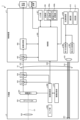
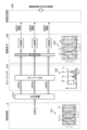
- FIG. 1 is a diagram showing an overall configuration of an endoscope system according to an embodiment.
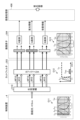
- FIG. 2 is a block diagram showing a functional configuration of a main part of the endoscope system according to the embodiment.
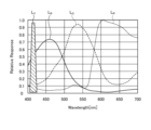
- FIG. 3 is a diagram showing the wavelength characteristics of the excitation light emitted by the second light source unit.
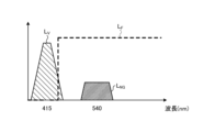
- FIG. 4 is a diagram showing the transmission characteristics of a cut filter.
- FIG. 5 is a diagram for explaining the observation principle in the fluorescent observation mode.
- FIG. 6 is a diagram for explaining the observation principle in the normal light observation mode.
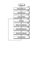
- FIG. 7 is a flow chart showing a control method before heat treatment.
- FIG. 8 is a diagram for explaining a control method before heat treatment.
- FIG. 9 is a diagram for explaining a control method before heat treatment.
- FIG. 10 is a flow chart showing a control method when performing a thermal treatment.
- FIG. 11 is a diagram for explaining a control method when performing a thermal treatment.
- FIG. 12 is a diagram for explaining a control method when performing a thermal treatment.
- FIG. 13 is a diagram for explaining a control method when performing a thermal treatment.
- FIG. 14 is a diagram for explaining a control method when performing a thermal treatment.
- FIG. 15 is a diagram for explaining a control method when performing heat treatment.
- FIG. 1 is a diagram showing an overall configuration of an endoscope system 1 according to an embodiment.
- the endoscope system 1 according to the present embodiment is an endoscope system used in endoscopic esophageal myotomy (POEM). Specifically, in endoscopic esophageal myotomy, the insertion section 21 of the endoscope 2 is inserted from the mouth of a subject into the esophagus to capture images of the inside of the subject, and a display image based on the captured image data is displayed on the display device 3. Then, the surgeon incises (thermally treats) the overdeveloped muscles of the esophagus and cardia using the thermal treatment device 5 while checking the displayed image. As shown in FIG. 1, the endoscope system 1 includes an endoscope 2, a display device 3, a control device 4, and a heat treatment device 5.
- POEM endoscopic esophageal myotomy
- the endoscope 2 generates image data (RAW data) by capturing an image of the inside of a subject, and outputs the image data to the control device 4.
- the endoscope 2 includes an insertion section 21, an operation section 22, and a universal cord 23.
- the insertion section 21 has at least a portion that is flexible and is inserted into a subject.
- the insertion section 21 includes a tip section 24 provided at the tip of the insertion section 21, a bending section 25 that is connected to a base end side (the operation section 22 side) of the tip section 24 and configured to be bendable, and a long flexible tube section 26 that is connected to the base end side of the bending section 25 and has flexibility.
- the operation unit 22 is connected to a base end portion of the insertion unit 21.
- the operation unit 22 receives various operations on the endoscope 2.
- the operation unit 22 is provided with a bending knob 221, an insertion port 222, and a plurality of operation members 223.
- the bending knob 221 is configured to be rotatable in response to a user operation by a user such as a surgeon.
- the bending knob 221 rotates to operate a bending mechanism (not shown) such as a metal or resin wire disposed in the insertion section 21. As a result, the bending section 25 is bent.
- the insertion port 222 communicates with a treatment instrument channel (not shown), which is a duct extending from the tip of the insertion portion 21, and is an insertion port for inserting a treatment instrument or the like into the treatment instrument channel from the outside of the endoscope 2.
- the multiple operating members 223 are composed of buttons and the like that accept various operations by a user such as an operator, and output operation signals corresponding to the various operations to the control device 4 via the universal cord 23.
- An example of the various operations is an operation to switch the observation mode of the endoscope system 1 to a normal light observation mode, a fluorescent observation mode, or a specific observation mode.
- the universal cord 23 extends from the operation section 22 in a direction different from the extending direction of the insertion section 21, and is a cord on which a light guide 231 (see FIG. 2) made of an optical fiber or the like, a first signal line 232 (see FIG. 2) for transmitting the above-mentioned image data, a second signal line 233 (see FIG. 2) for transmitting the above-mentioned operation signal, etc. are arranged.
- first and second connector sections 27, 28 and a cable 27a are provided, as shown in FIG. 1.
- the first connector portion 27 is detachably connected to the control device 4 .
- the cable 27 a is a coiled cable extending from the first connector portion 27 .
- the second connector portion 28 is provided at the tip of the cable 27 a and is detachably connected to the control device 4 .
- the display device 3 is composed of a display monitor such as a liquid crystal or organic EL (Electro Luminescence) display monitor, and under the control of the control device 4, displays an image based on image data that has been subjected to image processing in the control device 4, as well as various information related to the endoscope system 1.
- a display monitor such as a liquid crystal or organic EL (Electro Luminescence) display monitor
- the control device 4 corresponds to the medical device according to the present invention.
- This control device 4 is realized using a processor, which is a processing device having hardware such as a GPU (Graphics Processing Unit), FPGA (Field Programmable Gate Array), or CPU (Central Processing Unit), and a memory, which is a temporary storage area used by the processor.
- the control device 4 comprehensively controls the operation of each part of the endoscope system 1 according to the program recorded in the memory.
- the thermal treatment device 5 is, for example, an energy device such as a high-frequency knife that applies thermal treatment to biological tissue by supplying a high-frequency current to the biological tissue, or a laser irradiation device that applies thermal treatment to biological tissue by irradiating the biological tissue with a high-power infrared laser.
- the thermal treatment device 5 is inserted into the esophagus from the insertion port 222 via the treatment tool channel in the insertion section 21.
- the thermal treatment device 5 then applies thermal treatment to the muscles of the esophagus and cardia in response to user operations by a user such as an operator.
- FIG. 2 is a block diagram showing the functional configuration of the main parts of the endoscope system 1. As shown in FIG. In the following, the endoscope 2 and the control device 4 will be described in that order.
- the endoscope 2 includes an illumination optical system 201, an imaging optical system 202, a cut filter 203, an imaging element 204, an A/D conversion unit 205, a P/S conversion unit 206, an imaging recording unit 207, an imaging control unit 208, and a sensor unit 209.
- each of the illumination optical system 201, the imaging optical system 202, the cut filter 203, the imaging element 204, the A/D conversion unit 205, the P/S conversion unit 206, the imaging recording unit 207, the imaging control unit 208, and the sensor unit 209 are arranged within the tip portion 24.
- the illumination optical system 201 is composed of one or more lenses and irradiates the subject with illumination light supplied from a light guide 231 .
- the imaging optical system 202 is composed of one or more lenses, etc., and focuses light such as reflected light from the subject, returned light from the subject, and fluorescent light emitted by the subject, to form an image of the subject on the light receiving surface of the image sensor 204.
- the cut filter 203 is disposed on the optical axis L1 of the imaging optical system 202, between the imaging optical system 202 and the imaging element 204. The cut filter 203 blocks light in a predetermined wavelength band and transmits other light. The transmission characteristics of the cut filter 203 will be described later in the section "Configuration of the Control Device.”
- the image sensor 204 is configured using a CCD (Charge Coupled Device) or CMOS (Complementary Metal Oxide Semiconductor) image sensor in which one of the color filters constituting a Bayer array (RGGB) is arranged on each of a plurality of pixels arranged in a two-dimensional matrix.
- the image sensor 204 receives the subject image formed by the image pickup optical system 202 and passing through the cut filter 203 under the control of the image pickup control unit 208, and performs photoelectric conversion to generate a captured image (analog signal).
- the image sensor is configured integrally with a TOF (Time Of Flight) sensor that acquires subject distance information (hereinafter referred to as depth map information) by a TOF method.
- TOF Time Of Flight
- the depth map information is information in which the subject distance from the position of the image sensor 204 (the position of the tip 24) to the corresponding position on the observation target corresponding to the pixel position in the captured image is detected for each pixel position.
- the configuration for generating the depth map information is not limited to the above-mentioned TOF sensor, but may also employ a phase difference sensor, a stereo camera, or the like.
- the depth map information and the captured image will be collectively referred to as image data.
- the image sensor 204 outputs the image data to the A/D converter 205 .
- the A/D conversion unit 205 is configured using an A/D conversion circuit, etc., and performs A/D conversion processing on the analog image data input from the image sensor 204 under the control of the imaging control unit 208, and outputs the data to the P/S conversion unit 206.
- the P/S conversion unit 206 is constructed using a P/S conversion circuit, etc., and under the control of the imaging control unit 208, performs parallel/serial conversion on the digital image data input from the A/D conversion unit 205, and outputs it to the control device 4 via the first signal line 232.
- an E/O conversion unit that converts image data into an optical signal may be provided, and the image data may be output to the control device 4 by the optical signal.
- the image data may be transmitted to the control device 4 by wireless communication such as Wi-Fi (Wireless Fidelity) (registered trademark).
- the imaging and recording unit 207 is composed of a non-volatile memory or a volatile memory, and records various information related to the endoscope 2 (for example, pixel information of the imaging element 204, characteristics of the cut filter 203). The imaging and recording unit 207 also records various setting data and control parameters transmitted from the control device 4 via the second signal line 233.
- the imaging control unit 208 is realized using a TG (Timing Generator), a processor which is a processing device having hardware such as a CPU, and a memory which is a temporary storage area used by the processor.
- the imaging control unit 208 controls the operation of the imaging element 204, the A/D conversion unit 205, and the P/S conversion unit 206 based on the setting data received from the control device 4 via the second signal line 233.
- the sensor unit 209 is a sensor used to calculate the position of the tip of the insertion unit 21 (tip portion 24) and the direction in which the tip of the insertion unit 21 is facing (the imaging field of view of the tip).
- the sensor unit 209 is composed of multiple magnetic coils that generate magnetism.
- the control device 4 includes a focusing lens 401, a first light source unit 402, a second light source unit 403, a light source control unit 404, an S/P conversion unit 405, an image processing unit 406, an input unit 407, a recording unit 408, a control unit 409, a communication unit 410, and a receiving unit 411.
- the condenser lens 401 condenses the light emitted by each of the first and second light source units 402 and 403 , and emits the light to the light guide 231 .
- the first light source unit 402 emits visible white light (normal light) under the control of the light source control unit 404, and supplies the white light as illumination light to the light guide 231.
- the first light source unit 402 is configured using a collimator lens, a white LED (Light Emitting Diode) lamp, a driving driver, and the like.
- the first light source unit 402 may be configured to supply visible white light by simultaneously emitting light from a red LED lamp, a green LED lamp, and a blue LED lamp.
- the first light source unit 402 may also be configured with a halogen lamp, a xenon lamp, or the like.
- Fig. 3 is a diagram showing wavelength characteristics of the excitation light emitted by the second light source unit 403. Specifically, in Fig. 3, the horizontal axis indicates wavelength (nm) and the vertical axis indicates wavelength characteristics. Also, in Fig. 3, curves L- V indicate wavelength characteristics of the excitation light emitted by the second light source unit 403. Furthermore, in Fig. 3, curves L- B indicate a blue wavelength band, curves L- G indicate a green wavelength band, and curves L- R indicate a red wavelength band.
- the second light source unit 403 emits excitation light having a central wavelength (peak wavelength) of 415 nm and a wavelength band of 400 nm to 430 nm, as shown in Fig. 3.
- This second light source unit 403 is configured using a collimator lens, a semiconductor laser such as a violet LD (laser diode), a driver, etc.
- Fig. 4 is a diagram showing the transmission characteristics of the cut filter 203.
- the horizontal axis indicates wavelength (nm) and the vertical axis indicates wavelength characteristics.
- a curve L- F indicates the transmission characteristics of the cut filter 203
- a curve L- V indicates the wavelength characteristics of the excitation light.
- a curve L- NG indicates the wavelength characteristics of fluorescence generated by irradiating advanced glycation endproducts generated by thermal treatment of biological tissue with excitation light.
- the cut filter 203 blocks a portion of the excitation light reflected from the biological tissue in the observation area and transmits light in other wavelength bands including fluorescent components, as shown in Fig. 4. More specifically, the cut filter 203 blocks a portion of light in the short-wavelength wavelength band of 400 nm to less than 430 nm, including the excitation light, and transmits light in the long-wavelength wavelength band of more than 430 nm, including fluorescence generated by irradiating the excitation light on advanced glycation endproducts generated by heat treatment.
- the light source control unit 404 is realized using a processor, which is a processing device having hardware such as an FPGA or a CPU, and a memory, which is a temporary storage area used by the processor.
- the light source control unit 404 controls the light emission timing and light emission time of each of the first and second light source units 402 and 403 based on control data input from the control unit 409.
- the S/P conversion unit 405 performs serial/parallel conversion on the image data received from the endoscope 2 via the first signal line 232 , and outputs the converted data to the image processing unit 406 .
- an O/E converter that converts an optical signal into an electrical signal may be provided instead of the S/P converter 405.
- a communication module capable of receiving wireless signals may be provided instead of the S/P converter 405.
- the image processing unit 406 corresponds to the processor according to the present invention.
- This image processing unit 406 is realized using a processor, which is a processing device having hardware such as a GPU or FPGA, and a memory, which is a temporary storage area used by the processor. Then, under the control of the control unit 409, the image processing unit 406 performs a predetermined image processing on the image data of the parallel data input from the S/P conversion unit 405, and outputs the result to the display device 3.
- the predetermined image processing include demosaic processing, white balance processing, gain adjustment processing, gamma correction processing, and format conversion processing.
- the input unit 407 is configured using a mouse, foot switch, keyboard, buttons, switches, a touch panel, etc., and accepts user operations by a user such as a surgeon, and outputs an operation signal corresponding to the user operation to the control unit 409.
- the recording unit 408 is configured using a recording medium such as a volatile memory, a non-volatile memory, an SSD (Solid State Drive), an HDD (Hard Disk Drive), a memory card, etc.
- the recording unit 408 records data including various parameters necessary for the operation of the endoscope system 1.
- the recording unit 408 also includes a program recording unit 408a that records various programs for operating the endoscope system 1, and a learning model recording unit 408b, which will be described below.
- the learning model recording unit 408b records the learning model used in the image recognition performed by the control unit 409.
- the learning model is, for example, a model generated by machine learning using artificial intelligence (AI (Artificial Intelligence)).
- AI Artificial Intelligence
- the learning model is a model obtained by using image data captured of the treatment area of thermal treatment during endoscopic esophageal myotomy (POEM) as training data, and using machine learning (e.g., deep learning) to learn the treatment area based on the training data.
- POEM endoscopic esophageal myotomy
- the control unit 409 corresponds to the processor according to the present invention.
- This control unit 409 is realized using a processor, which is a processing device having hardware such as an FPGA or a CPU, and a memory, which is a temporary storage area used by the processor.
- the control unit 409 comprehensively controls each unit constituting the endoscope system 1.
- the communication unit 410 is an interface that communicates various data with an external tomography device (not shown) such as a computed tomography (CT) or magnetic resonance imaging (MRI) in accordance with a predetermined protocol. Under the control of the control unit 409, the communication unit 410 acquires tissue images, which are tomographic images captured by the tomography device.
- the communication between the communication unit 410 and the external tomography device may be wireless communication or wired communication. Also, a configuration may be adopted in which a tomography image (tissue image) captured by the tomography device is stored in a server or the like, and the communication unit 410 acquires the tomography image (tissue image) from the server.
- the receiver 411 receives the magnetic field emitted from the sensor unit 209. The receiver 411 then outputs a signal corresponding to the received magnetic field to the control unit 409.
- FIG. 5 is a diagram for explaining the observation principle in the fluorescent observation mode.
- the control device 4 irradiates the biological tissue O10 with excitation light (center wavelength 415 nm) by emitting light from the second light source unit 403.
- the control device 4 irradiates the biological tissue O10 with excitation light (center wavelength 415 nm) by emitting light from the second light source unit 403.
- the reflected light (hereinafter referred to as reflected light W10) including at least the excitation light component reflected by the biological tissue O10 and the return light is blocked by the cut filter 203 and the intensity is reduced, while a part of the component on the longer wavelength side than the blocked wavelength band is incident on the image sensor 204 without reducing the intensity.
- the cut filter 203 blocks most of the reflected light W10 in a wavelength band on the short wavelength side including the wavelength band of the excitation light, which is incident on the G pixel of the image sensor 204, and transmits a wavelength band on the long wavelength side of the blocked wavelength band. Also, as shown in graph G12 of Fig. 5, the cut filter 203 transmits the fluorescence WF10 auto-emitted by advanced glycation endproducts generated by the thermal treatment of the biological tissue O10. Therefore, the reflected light W10 and the fluorescence WF10 with reduced intensity are incident on each of the R pixel, G pixel, and B pixel of the image sensor 204.
- the G pixel in the image sensor 204 has sensitivity to the fluorescence WF10.
- the fluorescence is a very small reaction.
- the output value according to the fluorescence WF10 at the G pixel is a small value.
- the image processing unit 406 acquires image data (RAW data) from the image sensor 204, performs image processing on the output values of each of the G and B pixels contained in the image data, and generates a fluorescent image.
- the output value of the G pixel contains fluorescent information corresponding to the fluorescence WF10 emitted from the heat-treated area (advanced glycation end products) where the thermal treatment of the biological tissue O10 has been performed.
- the output value of the B pixel contains background information from the biological tissue O10 of the subject, including the heat-treated area. Then, by displaying the fluorescent image on the display device 3, it becomes possible to observe the heat-treated area where the thermal treatment of the biological tissue O10 has been performed.
- FIG. 6 is a diagram for explaining the observation principle in the normal light observation mode.
- the control device 4 causes the first light source unit 402 to emit light, thereby irradiating the living tissue O10 with white light.
- a part of the reflected light and return light hereinafter, referred to as reflected light WR30, WG30, and WB30
- reflected light WR30, WG30, and WB30 a part of the reflected light and return light reflected by the living tissue O10 is blocked by the cut filter 203, and the rest is incident on the image sensor 204.
- the cut filter 203 blocks reflected light of a wavelength band on the short wavelength side including the wavelength band of the excitation light. Therefore, the light component of the blue wavelength band incident on the B pixel of the image sensor 204 becomes smaller than that in a state in which the cut filter 203 is not arranged.
- the image processing unit 406 acquires image data (RAW data) from the imaging element 204, performs image processing on the output values of each of the R, G, and B pixels contained in the image data, and generates an observation image (white light image).
- the image processing unit 406 performs a white balance adjustment process to adjust the white balance so that the ratio of the red, green, and blue components is constant. Then, by displaying the observation image (white light image) on the display device 3, it becomes possible to observe a natural observation image (white light image) even when the cut filter 203 is arranged.
- control method executed by the control device 4
- the control method before heat treatment the control method executed by the control device 4 before performing heat treatment
- the control method executed by the control device 4 when performing the heat treatment hereinafter referred to as the control method when performing heat treatment
- Fig. 7 is a flow chart showing a control method before heat treatment.
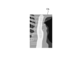
- Fig. 8 and Fig. 9 are diagrams explaining the control method before heat treatment. Specifically, Fig. 8 is a diagram showing a tissue image FA acquired in step S1A. Fig. 9 is a diagram corresponding to Fig. 8 and explaining step S1C.
- the control unit 409 controls the operation of the communication unit 410 in response to a user's operation on the input unit 407, and acquires a tissue image FA (FIG. 8) from an external tomography apparatus via the communication unit 410 (step S1A).
- the tissue image FA is a tomographic image captured by an external tomographic device of the same subject as the subject to be thermally treated by the thermal treatment device 5.
- the tissue image FA is provided with three-dimensional coordinates of a corresponding position on the observation target corresponding to the pixel position for each pixel. The three-dimensional coordinates are based on a specific coordinate system and are calculated by the tomographic device.
- step S1A the control unit 409 acquires range information indicating the treatment range of the thermal treatment in the tissue image FA (step S1B). Specifically, in step S1B, the control unit 409 acquires (extracts) range information indicating the thermal treatment target range ArT ( Figure 9) in the tissue image FA by image recognition using the learning model recorded in the learning model recording unit 408b.
- step S1B the image processing unit 406, under the control of the control unit 409, superimposes the treatment target range ArT on the tissue image FA as shown in Fig. 9 (step S1C). Then, the control unit 409 records the data of the tissue image FA on which the treatment target range ArT is superimposed in the recording unit 408.
- steps S1A to S1C complete the control method before heat treatment.
- FIG. 10 is a flow chart showing a control method when performing heat treatment.
- FIG. 11 to FIG. 15 are diagrams for explaining a control method when performing heat treatment.
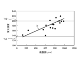
- FIG. 11 is a diagram showing a correlation (straight line L Y ) between the fluorescence intensity of the fluorescence auto-emitted by advanced glycation endproducts in the biological tissue and the invasiveness (depth and area) of the thermal treatment to the biological tissue.
- the vertical axis shows the fluorescence intensity
- the horizontal axis shows the invasiveness of the thermal treatment to the biological tissue.
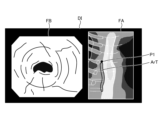
- FIG. 12 is a diagram corresponding to FIG. 8 and FIG. 9, and shows a display image DI generated in step S2B.
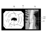
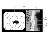
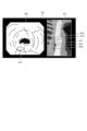
- FIG. 13 to FIG. 15 are diagrams corresponding to FIG. 12, and show steps S2D to S2H.
- the endoscope system 1 is already set in the following state. That is, the insertion portion 21 is inserted from the mouth of the subject into the esophagus, and the observation region of the endoscope system 1 is the region within the esophagus.
- the thermal treatment device 5 is inserted into the esophagus from the insertion port 222 via a treatment tool channel within the insertion portion 21, and is in a state where thermal treatment can be performed.
- the observation mode is switched to the specific observation mode in response to an operation of the operating member 223 by a user such as an operator to "switch the observation mode of the endoscope system 1 to the specific observation mode.”
- thermal denaturation image FB ( Figures 12 to 15) that makes it possible to identify thermally denatured regions Ar1 to Ar3 in the biological tissue (step S2A).
- thermally denatured region Ar1 is an insufficient thermal denaturation region where thermal denaturation is insufficient.
- Thermally denatured region Ar2 is an excessive thermal denaturation region where thermal denaturation is excessive.
- Thermally denatured region Ar3 is an appropriate thermal denaturation region where thermal denaturation is appropriate. Note that for ease of explanation, the appropriate thermal denaturation region Ar3 is not shown in the thermal denaturation image FB in Figures 13 to 15.
- the fluorescence image and the observation image are generated in a time-division manner by alternately switching between the fluorescence observation mode and the normal light observation mode.
- the image processing unit 406 executes a superimposition process to generate the thermally denatured image FB by superimposing the observation image (white light image) generated at approximately the same timing as the fluorescence image.
- examples of the superimposition processing executed by the image processing unit 406 include the following first and second superimposition processing.
- the first superposition process is a process of replacing areas in the observation image (white light image) that are at the same pixel positions as the thermally altered regions Ar1 to Ar3 in the fluorescence image with images of the thermally altered regions Ar1 to Ar3 in the fluorescence image.
- the second superposition process is a process (so-called alpha blending process) that changes the brightness of the color indicating the fluorescence applied to each pixel in the area that is at the same pixel position as the thermally denatured regions Ar1 to Ar3 in the observation image (white light image) depending on the fluorescence intensity at each pixel position in the thermally denatured regions Ar1 to Ar3 of the fluorescence image.
- step S2A the image processing unit 406 reads out the data of the tissue image FA recorded in the recording unit 408 in step S1C, and generates a display image DI in which the tissue image FA and the thermal denaturation image FB generated in step S2A are arranged side by side, as shown in FIG. 12 (step S2B).
- step S2C the control unit 409 starts a specification process for specifying the correspondence relationship for each pixel between the tissue image FA and the thermal denaturation image FB (step S2C). Specifically, in step S2C, the control unit 409 estimates the shape of the insertion unit 21 based on the magnetism emitted from the sensor unit 209 and received by the receiving unit 411, and calculates position information indicating the three-dimensional coordinates of the position of the tip (tip 24) of the insertion unit 21 and directional information indicating the field of view of the tip.
- the three-dimensional coordinates are coordinates in the same coordinate system as the three-dimensional coordinates assigned to each pixel in the tissue image FA.
- control unit 409 calculates, for each pixel of the thermal denaturation image FB, the three-dimensional coordinates of the corresponding position on the observation target corresponding to the pixel position, based on the calculated position information and directional information and the depth map information included in the image data used to generate the thermal denaturation image FB. Then, the control unit 409 compares the three-dimensional coordinates assigned to each pixel in the tissue image FA with the three-dimensional coordinates calculated for each pixel in the thermal denaturation image FB, and starts a specification process for specifying the correspondence relationship between each pixel of the tissue image FA and the thermal denaturation image FB.
- the image processing unit 406 under the control of the control unit 409, superimposes a position P1 on the tissue image FA in the display image DI, which is the subject of the thermal denaturation image FB and corresponds to the position of the area currently being observed by the endoscope 2, as shown in Figure 12.
- step S2D the control unit 409 executes notification control (step S2D). Specifically, in step S2D, the control unit 409 controls the operation of the image processing unit 406 to cause the display device 3 to display the display image DI shown in Fig. 12. That is, the display device 3 corresponds to a notification unit according to the present invention.
- the image processing unit 406 extracts the area formed by pixels whose fluorescence intensity is equal to or less than the first fluorescence intensity Th1 ( Figure 11) from among all pixels of the fluorescence image used to generate the thermal denaturation image FB as the thermal denaturation insufficient area Ar1 (step S2E). In addition, the image processing unit 406 extracts, from among all pixels of the fluorescence image used to generate the thermally denatured image FB, an area formed by pixels whose fluorescence intensity is equal to or greater than a second fluorescence intensity Th2 ( Figure 11) that is greater than the first fluorescence intensity Th1, as a thermally denatured excess area Ar2 (step S2F).
- the image processing unit 406 extracts as a suitable thermal denaturation region Ar3 a region formed by pixels whose fluorescence intensity is greater than the first fluorescence intensity Th1 and less than the second fluorescence intensity Th2 out of all pixels of the fluorescence image used to generate the thermal denaturation image FB (step S2G).
- steps S2E to S2G may be executed in the order of steps S2E to S2G, or in another order, or may be executed in parallel and substantially simultaneously.
- examples of the fluorescence intensity used in steps S2E to S2G include the output value of the G pixel in the image sensor 204, at least the g value of the pixel values (r, g, b) of each pixel after demosaicing of the image data acquired from the image sensor 204, or a luminance value corresponding to the Y signal (luminance signal).
- step S2H the image processor 406 updates the display image DI (step S2H).
- the control device 4 returns to step S2D.
- step S2H the image processing unit 406, under the control of the control unit 409, executes the following processing based on the result of the specific processing.
- the image processing unit 406 superimposes, on the tissue image FA in the display image DI, a thermally insufficient region Ar1 on the tissue image FA corresponding to the thermally insufficient region Ar1 on the fluorescent image extracted in step S2E, a thermally excessive region Ar2 on the tissue image FA corresponding to the thermally excessive region Ar2 on the fluorescent image extracted in step S2F, and a thermally adequate region Ar3 on the tissue image FA corresponding to the thermally adequate region Ar3 on the fluorescent image extracted in step S2G. That is, the thermally insufficient region Ar1, the thermally excessive region Ar2, and the thermally adequate region Ar3 correspond to the thermal denaturation information according to the present invention.
- the display image DI generated by the image processing unit 406 is changed as follows. First, in a state before thermal treatment is performed by the thermal treatment device 5, the image processing unit 406 generates a display image DI shown in FIG. Specifically, as can be judged from position P1, no thermal treatment has been performed in the display image DI, and therefore the image does not include the insufficient thermal denaturation area Ar1, the excessive thermal denaturation area Ar2, and the adequate thermal denaturation area Ar3 in the treatment target range ArT.
- the image processing unit 406 As the thermal treatment is performed by the thermal treatment device 5, the image processing unit 406 generates a display image DI shown in FIG. Specifically, as can be determined from position P1, the displayed image DI shows that the thermal treatment is performed from the top of the treatment target area ArT downwards to partway through the treatment target area ArT in Fig. 13, and therefore at least one of the thermally insufficient area Ar1, the thermally excessive area Ar2, and the thermally adequate area Ar3 exists partway through the treatment target area ArT. Note that in the example of Fig. 13, only the thermally adequate area Ar3 exists partway through.
- the image processing unit 406 when the thermal treatment is completed by the thermal treatment device 5, the image processing unit 406 generates a display image DI shown in FIG. Specifically, as can be determined from position P1, the display image DI has been completed with the thermal treatment up to the bottom of the treatment target range ArT in Fig. 14, and therefore is an image in which at least one of the thermal denaturation insufficient region Ar1, the thermal denaturation excessive region Ar2, and the thermal denaturation adequate region Ar3 exists throughout the treatment target range ArT.
- the thermal denaturation insufficient region Ar1, the thermal denaturation excessive region Ar2, and the thermal denaturation adequate region Ar3 exist throughout the entire treatment target range ArT.
- the thermal denaturation insufficient region Ar1 is represented by a hollow circle
- the thermal denaturation excessive region Ar2 is represented by a dotted circle
- the thermal denaturation adequate region Ar3 is represented by diagonal lines.
- the user after completing the thermal treatment, the user, such as the surgeon, can return the tip of the insertion portion 21 to the position of the thermally insufficient region Ar1 while checking the position P1 in the tissue image FA in the display image DI displayed on the display device 3, and can confirm the thermally insufficient region Ar1 in the thermally insufficient region FB, as shown in FIG. 15.
- the control device 4 acquires range information indicating the tissue image FA and the treatment target range ArT.
- the control device 4 also determines the state of thermal denaturation caused by the thermal treatment based on the fluorescence image.
- the control device 4 then causes the notification unit to notify thermal denaturation information indicating the state of thermal denaturation within the treatment target range ArT.
- the control device 4 displays a superimposed image in which the thermal denaturation information is superimposed on the tissue image FA on the display device 3, which is the notification unit. Therefore, according to the control device 4 of this embodiment, it is possible to allow a user such as an surgeon to determine whether or not thermal treatment was performed appropriately over the entire wide treatment target range ArT, thereby improving convenience.
- the control device 4 of this embodiment extracts a thermally insufficient region Ar1, a thermally excessive region Ar2, and an adequate thermal denaturation region Ar3 based on the fluorescence intensity of each pixel in the fluorescence image. Therefore, the state of thermal denaturation caused by the heat treatment can be determined simply and accurately.
- the medical device according to the present invention is mounted on an endoscope system used in endoscopic esophageal myotomy (POEM), but the present invention is not limited to this and may be mounted on an endoscope system used in other procedures, such as inferior turbinate mucosa cauterization for allergic rhinitis and blood cyst cauterization for endometriosis.
- POEM endoscopic esophageal myotomy
- the medical device according to the present invention is mounted on an endoscope system using a flexible endoscope, but the present invention is not limited to this and may also be mounted on an endoscope system using a rigid endoscope or an endoscope system using a medical surgery robot.
- the display device 3 is used as the notification unit according to the present invention, but this is not limited to this.
- the notification unit according to the present invention in addition to a configuration that notifies by displaying an image, other configurations such as a speaker that notifies by sound may also be used.
- thermal denaturation information indicating the state of thermal denaturation within the treatment target range ArT is displayed by superimposing a thermal denaturation-deficient region Ar1, a thermal denaturation-excessive region Ar2, and a thermal denaturation-adequate region Ar3 on a tissue image FA including the treatment target range ArT, but this is not limited to this.
- a thermal denaturation image FB is displayed without displaying the tissue image FA itself.
- the tissue image FA which is a tomographic image captured by a tomography apparatus, is used as the tissue image according to the present invention, but the present invention is not limited to this.
- an image hereinafter referred to as a concatenated image
- endoscopic images observation images (white light images)
- SLAM Simultaneous Localization and Mapping
- the tissue image according to the present invention may be a two-dimensional image or a three-dimensional image.
- the control device 4 calculated the three-dimensional coordinates of the position of the tip of the insertion portion 21 (tip portion 24) by using the configuration of the TOF sensor, the sensor unit 209, and the receiving unit 411 included in the imaging element 204, but this is not limited to this.
- the configuration of the above-mentioned TOF sensor, sensor unit 209, and receiving unit 411 may be omitted, and a configuration may be adopted in which the control device 4 calculates the three-dimensional coordinates of the position of the tip of the insertion portion 21 from the above-mentioned combined image.
- the control device 4 acquires (extracts) range information indicating the treatment target range ArT in the tissue image FA by image recognition using the learning model recorded in the learning model recording unit 408b, but this is not limited to this.
- the control device 4 may be configured to display a tissue image FA on the display device 3, while a user such as a surgeon operates the input unit 407 to acquire a range selected from within the tissue image FA as the treatment target range ArT.
Landscapes
- Health & Medical Sciences (AREA)
- Life Sciences & Earth Sciences (AREA)
- Surgery (AREA)
- Engineering & Computer Science (AREA)
- Biomedical Technology (AREA)
- Heart & Thoracic Surgery (AREA)
- Pathology (AREA)
- Radiology & Medical Imaging (AREA)
- Nuclear Medicine, Radiotherapy & Molecular Imaging (AREA)
- Biophysics (AREA)
- Physics & Mathematics (AREA)
- Optics & Photonics (AREA)
- Medical Informatics (AREA)
- Molecular Biology (AREA)
- Animal Behavior & Ethology (AREA)
- General Health & Medical Sciences (AREA)
- Public Health (AREA)
- Veterinary Medicine (AREA)
- Signal Processing (AREA)
- Endoscopes (AREA)
Abstract
Priority Applications (3)
| Application Number | Priority Date | Filing Date | Title |
|---|---|---|---|
| CN202380093073.7A CN120641017A (zh) | 2023-02-09 | 2023-02-09 | 医疗用装置、内窥镜系统、控制方法以及控制程序 |
| PCT/JP2023/004407 WO2024166312A1 (fr) | 2023-02-09 | 2023-02-09 | Dispositif médical, système d'endoscope, procédé de commande, et programme de commande |
| US19/287,964 US20250352048A1 (en) | 2023-02-09 | 2025-08-01 | Medical device, endoscope system, control method, and computer-readable recording medium |
Applications Claiming Priority (1)
| Application Number | Priority Date | Filing Date | Title |
|---|---|---|---|
| PCT/JP2023/004407 WO2024166312A1 (fr) | 2023-02-09 | 2023-02-09 | Dispositif médical, système d'endoscope, procédé de commande, et programme de commande |
Related Child Applications (1)
| Application Number | Title | Priority Date | Filing Date |
|---|---|---|---|
| US19/287,964 Continuation US20250352048A1 (en) | 2023-02-09 | 2025-08-01 | Medical device, endoscope system, control method, and computer-readable recording medium |
Publications (1)
| Publication Number | Publication Date |
|---|---|
| WO2024166312A1 true WO2024166312A1 (fr) | 2024-08-15 |
Family
ID=92262240
Family Applications (1)
| Application Number | Title | Priority Date | Filing Date |
|---|---|---|---|
| PCT/JP2023/004407 Ceased WO2024166312A1 (fr) | 2023-02-09 | 2023-02-09 | Dispositif médical, système d'endoscope, procédé de commande, et programme de commande |
Country Status (3)
| Country | Link |
|---|---|
| US (1) | US20250352048A1 (fr) |
| CN (1) | CN120641017A (fr) |
| WO (1) | WO2024166312A1 (fr) |
Citations (4)
| Publication number | Priority date | Publication date | Assignee | Title |
|---|---|---|---|---|
| JP2007244746A (ja) * | 2006-03-17 | 2007-09-27 | Olympus Medical Systems Corp | 観察システム |
| JP2008142355A (ja) * | 2006-12-11 | 2008-06-26 | Aloka Co Ltd | 画像形成システム |
| WO2020054723A1 (fr) * | 2018-09-10 | 2020-03-19 | オリンパス株式会社 | Dispositif d'observation d'agression thermique, système d'endoscope, système d'observation d'agression thermique et procédé d'observation d'agression thermique |
| JP2021000258A (ja) * | 2019-06-21 | 2021-01-07 | ソニー株式会社 | 医療用観察システム、医療用観察方法、および情報処理装置 |
-
2023
- 2023-02-09 WO PCT/JP2023/004407 patent/WO2024166312A1/fr not_active Ceased
- 2023-02-09 CN CN202380093073.7A patent/CN120641017A/zh active Pending
-
2025
- 2025-08-01 US US19/287,964 patent/US20250352048A1/en active Pending
Patent Citations (4)
| Publication number | Priority date | Publication date | Assignee | Title |
|---|---|---|---|---|
| JP2007244746A (ja) * | 2006-03-17 | 2007-09-27 | Olympus Medical Systems Corp | 観察システム |
| JP2008142355A (ja) * | 2006-12-11 | 2008-06-26 | Aloka Co Ltd | 画像形成システム |
| WO2020054723A1 (fr) * | 2018-09-10 | 2020-03-19 | オリンパス株式会社 | Dispositif d'observation d'agression thermique, système d'endoscope, système d'observation d'agression thermique et procédé d'observation d'agression thermique |
| JP2021000258A (ja) * | 2019-06-21 | 2021-01-07 | ソニー株式会社 | 医療用観察システム、医療用観察方法、および情報処理装置 |
Also Published As
| Publication number | Publication date |
|---|---|
| CN120641017A (zh) | 2025-09-12 |
| US20250352048A1 (en) | 2025-11-20 |
Similar Documents
| Publication | Publication Date | Title |
|---|---|---|
| JP5450527B2 (ja) | 内視鏡装置 | |
| JP2023010809A (ja) | 医療画像処理装置、内視鏡システム、医療画像処理装置の作動方法及びプログラム、記録媒体 | |
| JP6401800B2 (ja) | 画像処理装置、画像処理装置の作動方法、画像処理装置の作動プログラムおよび内視鏡装置 | |
| US20230000330A1 (en) | Medical observation system, medical imaging device and imaging method | |
| US20230248209A1 (en) | Assistant device, endoscopic system, assistant method, and computer-readable recording medium | |
| JP6230409B2 (ja) | 内視鏡装置 | |
| JPWO2017115442A1 (ja) | 画像処理装置、画像処理方法および画像処理プログラム | |
| CN114945314A (zh) | 医疗图像处理装置、内窥镜系统、诊断辅助方法及程序 | |
| US12121219B2 (en) | Medical image processing device, medical imaging device, medical observation system, image processing method, and computer-readable recording medium | |
| WO2024166312A1 (fr) | Dispositif médical, système d'endoscope, procédé de commande, et programme de commande | |
| US20250359729A1 (en) | Medical device, medical system, learning device, operation method of medical device, and computer-readable recording medium | |
| US20250348985A1 (en) | Image processing apparatus, medical system, image processing apparatus operation method, and computer-readable recording medium | |
| US20250352032A1 (en) | Medical device, medical system, learning device, method of operating medical device, and computer-readable recording medium | |
| US20250352029A1 (en) | Medical device, medical system, operation method of medical device, and computer-readable recording medium | |
| US20250359726A1 (en) | Medical apparatus, medical system, control method, and computer-readable recording medium | |
| US20250352028A1 (en) | Medical device, medical system, learning device, method of operating medical device, and computer-readable recording medium | |
| CN120641018A (zh) | 图像处理装置、医疗系统、图像处理装置的工作方法以及学习装置 | |
| US20250352026A1 (en) | Medical device, medical system, operation method of medical device, and computer-readable recording medium | |
| US20250356490A1 (en) | Assistance device, operation method of assistance device, computer-readable recording medium, medical system, and learning device | |
| WO2025234035A1 (fr) | Dispositif médical, système d'endoscope, procédé de commande, et programme de commande | |
| CN120641029A (zh) | 图像处理装置、医疗系统、图像处理装置的工作方法以及学习装置 | |
| WO2024166325A1 (fr) | Dispositif médical, système d'endoscope, procédé de commande, programme de commande et dispositif d'apprentissage | |
| WO2017046876A1 (fr) | Système d'endoscope, appareils de traitement d'image et procédés de traitement d'image |
Legal Events
| Date | Code | Title | Description |
|---|---|---|---|
| 121 | Ep: the epo has been informed by wipo that ep was designated in this application |
Ref document number: 23921143 Country of ref document: EP Kind code of ref document: A1 |
|
| WWE | Wipo information: entry into national phase |
Ref document number: 202380093073.7 Country of ref document: CN |
|
| NENP | Non-entry into the national phase |
Ref country code: DE |
|
| WWP | Wipo information: published in national office |
Ref document number: 202380093073.7 Country of ref document: CN |
|
| 122 | Ep: pct application non-entry in european phase |
Ref document number: 23921143 Country of ref document: EP Kind code of ref document: A1 |