WO2024166312A1 - Medical device, endoscope system, control method, and control program - Google Patents
Medical device, endoscope system, control method, and control program Download PDFInfo
- Publication number
- WO2024166312A1 WO2024166312A1 PCT/JP2023/004407 JP2023004407W WO2024166312A1 WO 2024166312 A1 WO2024166312 A1 WO 2024166312A1 JP 2023004407 W JP2023004407 W JP 2023004407W WO 2024166312 A1 WO2024166312 A1 WO 2024166312A1
- Authority
- WO
- WIPO (PCT)
- Prior art keywords
- image
- thermal denaturation
- tissue
- treatment
- thermal
- Prior art date
- Legal status (The legal status is an assumption and is not a legal conclusion. Google has not performed a legal analysis and makes no representation as to the accuracy of the status listed.)
- Ceased
Links
Images


Classifications
-
- A—HUMAN NECESSITIES
- A61—MEDICAL OR VETERINARY SCIENCE; HYGIENE
- A61B—DIAGNOSIS; SURGERY; IDENTIFICATION
- A61B1/00—Instruments for performing medical examinations of the interior of cavities or tubes of the body by visual or photographical inspection, e.g. endoscopes; Illuminating arrangements therefor
- A61B1/00002—Operational features of endoscopes
- A61B1/00004—Operational features of endoscopes characterised by electronic signal processing
- A61B1/00009—Operational features of endoscopes characterised by electronic signal processing of image signals during a use of endoscope
- A61B1/000095—Operational features of endoscopes characterised by electronic signal processing of image signals during a use of endoscope for image enhancement
-
- A—HUMAN NECESSITIES
- A61—MEDICAL OR VETERINARY SCIENCE; HYGIENE
- A61B—DIAGNOSIS; SURGERY; IDENTIFICATION
- A61B1/00—Instruments for performing medical examinations of the interior of cavities or tubes of the body by visual or photographical inspection, e.g. endoscopes; Illuminating arrangements therefor
- A61B1/00002—Operational features of endoscopes
- A61B1/00004—Operational features of endoscopes characterised by electronic signal processing
- A61B1/00009—Operational features of endoscopes characterised by electronic signal processing of image signals during a use of endoscope
- A61B1/000094—Operational features of endoscopes characterised by electronic signal processing of image signals during a use of endoscope extracting biological structures
-
- A—HUMAN NECESSITIES
- A61—MEDICAL OR VETERINARY SCIENCE; HYGIENE
- A61B—DIAGNOSIS; SURGERY; IDENTIFICATION
- A61B1/00—Instruments for performing medical examinations of the interior of cavities or tubes of the body by visual or photographical inspection, e.g. endoscopes; Illuminating arrangements therefor
- A61B1/00002—Operational features of endoscopes
- A61B1/00043—Operational features of endoscopes provided with output arrangements
- A61B1/00045—Display arrangement
- A61B1/0005—Display arrangement combining images e.g. side-by-side, superimposed or tiled
-
- A—HUMAN NECESSITIES
- A61—MEDICAL OR VETERINARY SCIENCE; HYGIENE
- A61B—DIAGNOSIS; SURGERY; IDENTIFICATION
- A61B1/00—Instruments for performing medical examinations of the interior of cavities or tubes of the body by visual or photographical inspection, e.g. endoscopes; Illuminating arrangements therefor
- A61B1/04—Instruments for performing medical examinations of the interior of cavities or tubes of the body by visual or photographical inspection, e.g. endoscopes; Illuminating arrangements therefor combined with photographic or television appliances
- A61B1/043—Instruments for performing medical examinations of the interior of cavities or tubes of the body by visual or photographical inspection, e.g. endoscopes; Illuminating arrangements therefor combined with photographic or television appliances for fluorescence imaging
-
- A—HUMAN NECESSITIES
- A61—MEDICAL OR VETERINARY SCIENCE; HYGIENE
- A61B—DIAGNOSIS; SURGERY; IDENTIFICATION
- A61B1/00—Instruments for performing medical examinations of the interior of cavities or tubes of the body by visual or photographical inspection, e.g. endoscopes; Illuminating arrangements therefor
- A61B1/04—Instruments for performing medical examinations of the interior of cavities or tubes of the body by visual or photographical inspection, e.g. endoscopes; Illuminating arrangements therefor combined with photographic or television appliances
- A61B1/045—Control thereof
-
- A—HUMAN NECESSITIES
- A61—MEDICAL OR VETERINARY SCIENCE; HYGIENE
- A61B—DIAGNOSIS; SURGERY; IDENTIFICATION
- A61B1/00—Instruments for performing medical examinations of the interior of cavities or tubes of the body by visual or photographical inspection, e.g. endoscopes; Illuminating arrangements therefor
- A61B1/04—Instruments for performing medical examinations of the interior of cavities or tubes of the body by visual or photographical inspection, e.g. endoscopes; Illuminating arrangements therefor combined with photographic or television appliances
- A61B1/05—Instruments for performing medical examinations of the interior of cavities or tubes of the body by visual or photographical inspection, e.g. endoscopes; Illuminating arrangements therefor combined with photographic or television appliances characterised by the image sensor, e.g. camera, being in the distal end portion
-
- A—HUMAN NECESSITIES
- A61—MEDICAL OR VETERINARY SCIENCE; HYGIENE
- A61B—DIAGNOSIS; SURGERY; IDENTIFICATION
- A61B1/00—Instruments for performing medical examinations of the interior of cavities or tubes of the body by visual or photographical inspection, e.g. endoscopes; Illuminating arrangements therefor
- A61B1/06—Instruments for performing medical examinations of the interior of cavities or tubes of the body by visual or photographical inspection, e.g. endoscopes; Illuminating arrangements therefor with illuminating arrangements
- A61B1/0638—Instruments for performing medical examinations of the interior of cavities or tubes of the body by visual or photographical inspection, e.g. endoscopes; Illuminating arrangements therefor with illuminating arrangements providing two or more wavelengths
Definitions
- the present invention relates to a medical device, an endoscope system, a control method, and a control program.
- Patent Literature 1 a technique for visualizing the state of thermal denaturation of biological tissue during thermal treatment of the biological tissue by an energy device or the like (see, for example, Patent Document 1).
- the state of thermal denaturation of biological tissue is visualized based on an image obtained by capturing fluorescence generated from the biological tissue by irradiating the biological tissue with excitation light.
- a region where the fluorescence intensity is higher than a preset fluorescence intensity is displayed as a region of high thermal denaturation.
- the present invention has been made in consideration of the above, and aims to provide a medical device, an endoscope system, a control method, and a control program that can improve convenience.
- the medical device of the present invention includes a processor that processes captured images of fluorescence generated from biological tissue by irradiating the biological tissue with excitation light, and the processor acquires a tissue image including a target area of thermal treatment in the biological tissue, acquires range information in the tissue image that indicates the treatment range of the thermal treatment, determines the state of thermal denaturation caused by the thermal treatment based on the captured image, and causes an alarm unit to notify thermal denaturation information indicating the state of the thermal denaturation within the treatment range.
- the endoscope system comprises a light source device that irradiates excitation light, an endoscope that can be inserted into a subject and outputs an image of fluorescence generated from biological tissue in the subject by irradiating the biological tissue with the excitation light, and a medical device having a processor that processes the image, and the processor acquires a tissue image including a target site of thermal treatment in the biological tissue, acquires range information in the tissue image that indicates the treatment range of the thermal treatment, determines the state of thermal denaturation caused by the thermal treatment based on the image, and causes an alarm unit to notify the thermal denaturation information indicating the state of the thermal denaturation within the treatment range.
- the control method according to the present invention is a control method executed by a medical device, which acquires a tissue image including a target area of a thermal treatment in biological tissue, acquires range information in the tissue image indicating a treatment range of the thermal treatment, determines a state of thermal denaturation caused by the thermal treatment based on an image of fluorescence generated from the biological tissue by irradiating the biological tissue with excitation light, and causes an alarm unit to notify thermal denaturation information indicating the state of the thermal denaturation within the treatment range.
- the control program according to the present invention is a control program executed by a medical device, and the control program instructs the medical device to perform the following: acquire a tissue image including a target area of thermal treatment in biological tissue, acquire range information in the tissue image indicating the treatment range of the thermal treatment, determine the state of thermal denaturation caused by the thermal treatment based on an image of fluorescence generated from the biological tissue by irradiating the biological tissue with excitation light, and cause an alarm unit to notify thermal denaturation information indicating the state of the thermal denaturation within the treatment range.
- the medical device, endoscope system, control method, and control program of the present invention can improve convenience.
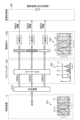
- FIG. 1 is a diagram showing an overall configuration of an endoscope system according to an embodiment.
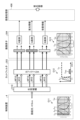
- FIG. 2 is a block diagram showing a functional configuration of a main part of the endoscope system according to the embodiment.
- FIG. 3 is a diagram showing the wavelength characteristics of the excitation light emitted by the second light source unit.
- FIG. 4 is a diagram showing the transmission characteristics of a cut filter.
- FIG. 5 is a diagram for explaining the observation principle in the fluorescent observation mode.
- FIG. 6 is a diagram for explaining the observation principle in the normal light observation mode.
- FIG. 7 is a flow chart showing a control method before heat treatment.
- FIG. 8 is a diagram for explaining a control method before heat treatment.
- FIG. 9 is a diagram for explaining a control method before heat treatment.
- FIG. 10 is a flow chart showing a control method when performing a thermal treatment.
- FIG. 11 is a diagram for explaining a control method when performing a thermal treatment.
- FIG. 12 is a diagram for explaining a control method when performing a thermal treatment.
- FIG. 13 is a diagram for explaining a control method when performing a thermal treatment.
- FIG. 14 is a diagram for explaining a control method when performing a thermal treatment.
- FIG. 15 is a diagram for explaining a control method when performing heat treatment.
- FIG. 1 is a diagram showing an overall configuration of an endoscope system 1 according to an embodiment.
- the endoscope system 1 according to the present embodiment is an endoscope system used in endoscopic esophageal myotomy (POEM). Specifically, in endoscopic esophageal myotomy, the insertion section 21 of the endoscope 2 is inserted from the mouth of a subject into the esophagus to capture images of the inside of the subject, and a display image based on the captured image data is displayed on the display device 3. Then, the surgeon incises (thermally treats) the overdeveloped muscles of the esophagus and cardia using the thermal treatment device 5 while checking the displayed image. As shown in FIG. 1, the endoscope system 1 includes an endoscope 2, a display device 3, a control device 4, and a heat treatment device 5.
- POEM endoscopic esophageal myotomy
- the endoscope 2 generates image data (RAW data) by capturing an image of the inside of a subject, and outputs the image data to the control device 4.
- the endoscope 2 includes an insertion section 21, an operation section 22, and a universal cord 23.
- the insertion section 21 has at least a portion that is flexible and is inserted into a subject.
- the insertion section 21 includes a tip section 24 provided at the tip of the insertion section 21, a bending section 25 that is connected to a base end side (the operation section 22 side) of the tip section 24 and configured to be bendable, and a long flexible tube section 26 that is connected to the base end side of the bending section 25 and has flexibility.
- the operation unit 22 is connected to a base end portion of the insertion unit 21.
- the operation unit 22 receives various operations on the endoscope 2.
- the operation unit 22 is provided with a bending knob 221, an insertion port 222, and a plurality of operation members 223.
- the bending knob 221 is configured to be rotatable in response to a user operation by a user such as a surgeon.
- the bending knob 221 rotates to operate a bending mechanism (not shown) such as a metal or resin wire disposed in the insertion section 21. As a result, the bending section 25 is bent.
- the insertion port 222 communicates with a treatment instrument channel (not shown), which is a duct extending from the tip of the insertion portion 21, and is an insertion port for inserting a treatment instrument or the like into the treatment instrument channel from the outside of the endoscope 2.
- the multiple operating members 223 are composed of buttons and the like that accept various operations by a user such as an operator, and output operation signals corresponding to the various operations to the control device 4 via the universal cord 23.
- An example of the various operations is an operation to switch the observation mode of the endoscope system 1 to a normal light observation mode, a fluorescent observation mode, or a specific observation mode.
- the universal cord 23 extends from the operation section 22 in a direction different from the extending direction of the insertion section 21, and is a cord on which a light guide 231 (see FIG. 2) made of an optical fiber or the like, a first signal line 232 (see FIG. 2) for transmitting the above-mentioned image data, a second signal line 233 (see FIG. 2) for transmitting the above-mentioned operation signal, etc. are arranged.
- first and second connector sections 27, 28 and a cable 27a are provided, as shown in FIG. 1.
- the first connector portion 27 is detachably connected to the control device 4 .
- the cable 27 a is a coiled cable extending from the first connector portion 27 .
- the second connector portion 28 is provided at the tip of the cable 27 a and is detachably connected to the control device 4 .
- the display device 3 is composed of a display monitor such as a liquid crystal or organic EL (Electro Luminescence) display monitor, and under the control of the control device 4, displays an image based on image data that has been subjected to image processing in the control device 4, as well as various information related to the endoscope system 1.
- a display monitor such as a liquid crystal or organic EL (Electro Luminescence) display monitor
- the control device 4 corresponds to the medical device according to the present invention.
- This control device 4 is realized using a processor, which is a processing device having hardware such as a GPU (Graphics Processing Unit), FPGA (Field Programmable Gate Array), or CPU (Central Processing Unit), and a memory, which is a temporary storage area used by the processor.
- the control device 4 comprehensively controls the operation of each part of the endoscope system 1 according to the program recorded in the memory.
- the thermal treatment device 5 is, for example, an energy device such as a high-frequency knife that applies thermal treatment to biological tissue by supplying a high-frequency current to the biological tissue, or a laser irradiation device that applies thermal treatment to biological tissue by irradiating the biological tissue with a high-power infrared laser.
- the thermal treatment device 5 is inserted into the esophagus from the insertion port 222 via the treatment tool channel in the insertion section 21.
- the thermal treatment device 5 then applies thermal treatment to the muscles of the esophagus and cardia in response to user operations by a user such as an operator.
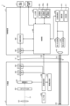
- FIG. 2 is a block diagram showing the functional configuration of the main parts of the endoscope system 1. As shown in FIG. In the following, the endoscope 2 and the control device 4 will be described in that order.
- the endoscope 2 includes an illumination optical system 201, an imaging optical system 202, a cut filter 203, an imaging element 204, an A/D conversion unit 205, a P/S conversion unit 206, an imaging recording unit 207, an imaging control unit 208, and a sensor unit 209.
- each of the illumination optical system 201, the imaging optical system 202, the cut filter 203, the imaging element 204, the A/D conversion unit 205, the P/S conversion unit 206, the imaging recording unit 207, the imaging control unit 208, and the sensor unit 209 are arranged within the tip portion 24.
- the illumination optical system 201 is composed of one or more lenses and irradiates the subject with illumination light supplied from a light guide 231 .
- the imaging optical system 202 is composed of one or more lenses, etc., and focuses light such as reflected light from the subject, returned light from the subject, and fluorescent light emitted by the subject, to form an image of the subject on the light receiving surface of the image sensor 204.
- the cut filter 203 is disposed on the optical axis L1 of the imaging optical system 202, between the imaging optical system 202 and the imaging element 204. The cut filter 203 blocks light in a predetermined wavelength band and transmits other light. The transmission characteristics of the cut filter 203 will be described later in the section "Configuration of the Control Device.”
- the image sensor 204 is configured using a CCD (Charge Coupled Device) or CMOS (Complementary Metal Oxide Semiconductor) image sensor in which one of the color filters constituting a Bayer array (RGGB) is arranged on each of a plurality of pixels arranged in a two-dimensional matrix.
- the image sensor 204 receives the subject image formed by the image pickup optical system 202 and passing through the cut filter 203 under the control of the image pickup control unit 208, and performs photoelectric conversion to generate a captured image (analog signal).
- the image sensor is configured integrally with a TOF (Time Of Flight) sensor that acquires subject distance information (hereinafter referred to as depth map information) by a TOF method.
- TOF Time Of Flight
- the depth map information is information in which the subject distance from the position of the image sensor 204 (the position of the tip 24) to the corresponding position on the observation target corresponding to the pixel position in the captured image is detected for each pixel position.
- the configuration for generating the depth map information is not limited to the above-mentioned TOF sensor, but may also employ a phase difference sensor, a stereo camera, or the like.
- the depth map information and the captured image will be collectively referred to as image data.
- the image sensor 204 outputs the image data to the A/D converter 205 .
- the A/D conversion unit 205 is configured using an A/D conversion circuit, etc., and performs A/D conversion processing on the analog image data input from the image sensor 204 under the control of the imaging control unit 208, and outputs the data to the P/S conversion unit 206.
- the P/S conversion unit 206 is constructed using a P/S conversion circuit, etc., and under the control of the imaging control unit 208, performs parallel/serial conversion on the digital image data input from the A/D conversion unit 205, and outputs it to the control device 4 via the first signal line 232.
- an E/O conversion unit that converts image data into an optical signal may be provided, and the image data may be output to the control device 4 by the optical signal.
- the image data may be transmitted to the control device 4 by wireless communication such as Wi-Fi (Wireless Fidelity) (registered trademark).
- the imaging and recording unit 207 is composed of a non-volatile memory or a volatile memory, and records various information related to the endoscope 2 (for example, pixel information of the imaging element 204, characteristics of the cut filter 203). The imaging and recording unit 207 also records various setting data and control parameters transmitted from the control device 4 via the second signal line 233.
- the imaging control unit 208 is realized using a TG (Timing Generator), a processor which is a processing device having hardware such as a CPU, and a memory which is a temporary storage area used by the processor.
- the imaging control unit 208 controls the operation of the imaging element 204, the A/D conversion unit 205, and the P/S conversion unit 206 based on the setting data received from the control device 4 via the second signal line 233.
- the sensor unit 209 is a sensor used to calculate the position of the tip of the insertion unit 21 (tip portion 24) and the direction in which the tip of the insertion unit 21 is facing (the imaging field of view of the tip).
- the sensor unit 209 is composed of multiple magnetic coils that generate magnetism.
- the control device 4 includes a focusing lens 401, a first light source unit 402, a second light source unit 403, a light source control unit 404, an S/P conversion unit 405, an image processing unit 406, an input unit 407, a recording unit 408, a control unit 409, a communication unit 410, and a receiving unit 411.
- the condenser lens 401 condenses the light emitted by each of the first and second light source units 402 and 403 , and emits the light to the light guide 231 .
- the first light source unit 402 emits visible white light (normal light) under the control of the light source control unit 404, and supplies the white light as illumination light to the light guide 231.
- the first light source unit 402 is configured using a collimator lens, a white LED (Light Emitting Diode) lamp, a driving driver, and the like.
- the first light source unit 402 may be configured to supply visible white light by simultaneously emitting light from a red LED lamp, a green LED lamp, and a blue LED lamp.
- the first light source unit 402 may also be configured with a halogen lamp, a xenon lamp, or the like.
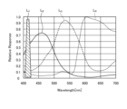
- Fig. 3 is a diagram showing wavelength characteristics of the excitation light emitted by the second light source unit 403. Specifically, in Fig. 3, the horizontal axis indicates wavelength (nm) and the vertical axis indicates wavelength characteristics. Also, in Fig. 3, curves L- V indicate wavelength characteristics of the excitation light emitted by the second light source unit 403. Furthermore, in Fig. 3, curves L- B indicate a blue wavelength band, curves L- G indicate a green wavelength band, and curves L- R indicate a red wavelength band.
- the second light source unit 403 emits excitation light having a central wavelength (peak wavelength) of 415 nm and a wavelength band of 400 nm to 430 nm, as shown in Fig. 3.
- This second light source unit 403 is configured using a collimator lens, a semiconductor laser such as a violet LD (laser diode), a driver, etc.
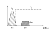
- Fig. 4 is a diagram showing the transmission characteristics of the cut filter 203.
- the horizontal axis indicates wavelength (nm) and the vertical axis indicates wavelength characteristics.
- a curve L- F indicates the transmission characteristics of the cut filter 203
- a curve L- V indicates the wavelength characteristics of the excitation light.
- a curve L- NG indicates the wavelength characteristics of fluorescence generated by irradiating advanced glycation endproducts generated by thermal treatment of biological tissue with excitation light.
- the cut filter 203 blocks a portion of the excitation light reflected from the biological tissue in the observation area and transmits light in other wavelength bands including fluorescent components, as shown in Fig. 4. More specifically, the cut filter 203 blocks a portion of light in the short-wavelength wavelength band of 400 nm to less than 430 nm, including the excitation light, and transmits light in the long-wavelength wavelength band of more than 430 nm, including fluorescence generated by irradiating the excitation light on advanced glycation endproducts generated by heat treatment.
- the light source control unit 404 is realized using a processor, which is a processing device having hardware such as an FPGA or a CPU, and a memory, which is a temporary storage area used by the processor.
- the light source control unit 404 controls the light emission timing and light emission time of each of the first and second light source units 402 and 403 based on control data input from the control unit 409.
- the S/P conversion unit 405 performs serial/parallel conversion on the image data received from the endoscope 2 via the first signal line 232 , and outputs the converted data to the image processing unit 406 .
- an O/E converter that converts an optical signal into an electrical signal may be provided instead of the S/P converter 405.
- a communication module capable of receiving wireless signals may be provided instead of the S/P converter 405.
- the image processing unit 406 corresponds to the processor according to the present invention.
- This image processing unit 406 is realized using a processor, which is a processing device having hardware such as a GPU or FPGA, and a memory, which is a temporary storage area used by the processor. Then, under the control of the control unit 409, the image processing unit 406 performs a predetermined image processing on the image data of the parallel data input from the S/P conversion unit 405, and outputs the result to the display device 3.
- the predetermined image processing include demosaic processing, white balance processing, gain adjustment processing, gamma correction processing, and format conversion processing.
- the input unit 407 is configured using a mouse, foot switch, keyboard, buttons, switches, a touch panel, etc., and accepts user operations by a user such as a surgeon, and outputs an operation signal corresponding to the user operation to the control unit 409.
- the recording unit 408 is configured using a recording medium such as a volatile memory, a non-volatile memory, an SSD (Solid State Drive), an HDD (Hard Disk Drive), a memory card, etc.
- the recording unit 408 records data including various parameters necessary for the operation of the endoscope system 1.
- the recording unit 408 also includes a program recording unit 408a that records various programs for operating the endoscope system 1, and a learning model recording unit 408b, which will be described below.
- the learning model recording unit 408b records the learning model used in the image recognition performed by the control unit 409.
- the learning model is, for example, a model generated by machine learning using artificial intelligence (AI (Artificial Intelligence)).
- AI Artificial Intelligence
- the learning model is a model obtained by using image data captured of the treatment area of thermal treatment during endoscopic esophageal myotomy (POEM) as training data, and using machine learning (e.g., deep learning) to learn the treatment area based on the training data.
- POEM endoscopic esophageal myotomy
- the control unit 409 corresponds to the processor according to the present invention.
- This control unit 409 is realized using a processor, which is a processing device having hardware such as an FPGA or a CPU, and a memory, which is a temporary storage area used by the processor.
- the control unit 409 comprehensively controls each unit constituting the endoscope system 1.
- the communication unit 410 is an interface that communicates various data with an external tomography device (not shown) such as a computed tomography (CT) or magnetic resonance imaging (MRI) in accordance with a predetermined protocol. Under the control of the control unit 409, the communication unit 410 acquires tissue images, which are tomographic images captured by the tomography device.
- the communication between the communication unit 410 and the external tomography device may be wireless communication or wired communication. Also, a configuration may be adopted in which a tomography image (tissue image) captured by the tomography device is stored in a server or the like, and the communication unit 410 acquires the tomography image (tissue image) from the server.
- the receiver 411 receives the magnetic field emitted from the sensor unit 209. The receiver 411 then outputs a signal corresponding to the received magnetic field to the control unit 409.
- FIG. 5 is a diagram for explaining the observation principle in the fluorescent observation mode.
- the control device 4 irradiates the biological tissue O10 with excitation light (center wavelength 415 nm) by emitting light from the second light source unit 403.
- the control device 4 irradiates the biological tissue O10 with excitation light (center wavelength 415 nm) by emitting light from the second light source unit 403.
- the reflected light (hereinafter referred to as reflected light W10) including at least the excitation light component reflected by the biological tissue O10 and the return light is blocked by the cut filter 203 and the intensity is reduced, while a part of the component on the longer wavelength side than the blocked wavelength band is incident on the image sensor 204 without reducing the intensity.
- the cut filter 203 blocks most of the reflected light W10 in a wavelength band on the short wavelength side including the wavelength band of the excitation light, which is incident on the G pixel of the image sensor 204, and transmits a wavelength band on the long wavelength side of the blocked wavelength band. Also, as shown in graph G12 of Fig. 5, the cut filter 203 transmits the fluorescence WF10 auto-emitted by advanced glycation endproducts generated by the thermal treatment of the biological tissue O10. Therefore, the reflected light W10 and the fluorescence WF10 with reduced intensity are incident on each of the R pixel, G pixel, and B pixel of the image sensor 204.
- the G pixel in the image sensor 204 has sensitivity to the fluorescence WF10.
- the fluorescence is a very small reaction.
- the output value according to the fluorescence WF10 at the G pixel is a small value.
- the image processing unit 406 acquires image data (RAW data) from the image sensor 204, performs image processing on the output values of each of the G and B pixels contained in the image data, and generates a fluorescent image.
- the output value of the G pixel contains fluorescent information corresponding to the fluorescence WF10 emitted from the heat-treated area (advanced glycation end products) where the thermal treatment of the biological tissue O10 has been performed.
- the output value of the B pixel contains background information from the biological tissue O10 of the subject, including the heat-treated area. Then, by displaying the fluorescent image on the display device 3, it becomes possible to observe the heat-treated area where the thermal treatment of the biological tissue O10 has been performed.
- FIG. 6 is a diagram for explaining the observation principle in the normal light observation mode.
- the control device 4 causes the first light source unit 402 to emit light, thereby irradiating the living tissue O10 with white light.
- a part of the reflected light and return light hereinafter, referred to as reflected light WR30, WG30, and WB30
- reflected light WR30, WG30, and WB30 a part of the reflected light and return light reflected by the living tissue O10 is blocked by the cut filter 203, and the rest is incident on the image sensor 204.
- the cut filter 203 blocks reflected light of a wavelength band on the short wavelength side including the wavelength band of the excitation light. Therefore, the light component of the blue wavelength band incident on the B pixel of the image sensor 204 becomes smaller than that in a state in which the cut filter 203 is not arranged.
- the image processing unit 406 acquires image data (RAW data) from the imaging element 204, performs image processing on the output values of each of the R, G, and B pixels contained in the image data, and generates an observation image (white light image).
- the image processing unit 406 performs a white balance adjustment process to adjust the white balance so that the ratio of the red, green, and blue components is constant. Then, by displaying the observation image (white light image) on the display device 3, it becomes possible to observe a natural observation image (white light image) even when the cut filter 203 is arranged.
- control method executed by the control device 4
- the control method before heat treatment the control method executed by the control device 4 before performing heat treatment
- the control method executed by the control device 4 when performing the heat treatment hereinafter referred to as the control method when performing heat treatment
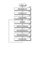
- Fig. 7 is a flow chart showing a control method before heat treatment.
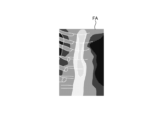
- Fig. 8 and Fig. 9 are diagrams explaining the control method before heat treatment. Specifically, Fig. 8 is a diagram showing a tissue image FA acquired in step S1A. Fig. 9 is a diagram corresponding to Fig. 8 and explaining step S1C.
- the control unit 409 controls the operation of the communication unit 410 in response to a user's operation on the input unit 407, and acquires a tissue image FA (FIG. 8) from an external tomography apparatus via the communication unit 410 (step S1A).
- the tissue image FA is a tomographic image captured by an external tomographic device of the same subject as the subject to be thermally treated by the thermal treatment device 5.
- the tissue image FA is provided with three-dimensional coordinates of a corresponding position on the observation target corresponding to the pixel position for each pixel. The three-dimensional coordinates are based on a specific coordinate system and are calculated by the tomographic device.
- step S1A the control unit 409 acquires range information indicating the treatment range of the thermal treatment in the tissue image FA (step S1B). Specifically, in step S1B, the control unit 409 acquires (extracts) range information indicating the thermal treatment target range ArT ( Figure 9) in the tissue image FA by image recognition using the learning model recorded in the learning model recording unit 408b.
- step S1B the image processing unit 406, under the control of the control unit 409, superimposes the treatment target range ArT on the tissue image FA as shown in Fig. 9 (step S1C). Then, the control unit 409 records the data of the tissue image FA on which the treatment target range ArT is superimposed in the recording unit 408.
- steps S1A to S1C complete the control method before heat treatment.
- FIG. 10 is a flow chart showing a control method when performing heat treatment.
- FIG. 11 to FIG. 15 are diagrams for explaining a control method when performing heat treatment.
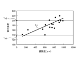
- FIG. 11 is a diagram showing a correlation (straight line L Y ) between the fluorescence intensity of the fluorescence auto-emitted by advanced glycation endproducts in the biological tissue and the invasiveness (depth and area) of the thermal treatment to the biological tissue.
- the vertical axis shows the fluorescence intensity
- the horizontal axis shows the invasiveness of the thermal treatment to the biological tissue.
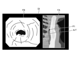
- FIG. 12 is a diagram corresponding to FIG. 8 and FIG. 9, and shows a display image DI generated in step S2B.
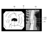
- FIG. 13 to FIG. 15 are diagrams corresponding to FIG. 12, and show steps S2D to S2H.
- the endoscope system 1 is already set in the following state. That is, the insertion portion 21 is inserted from the mouth of the subject into the esophagus, and the observation region of the endoscope system 1 is the region within the esophagus.
- the thermal treatment device 5 is inserted into the esophagus from the insertion port 222 via a treatment tool channel within the insertion portion 21, and is in a state where thermal treatment can be performed.
- the observation mode is switched to the specific observation mode in response to an operation of the operating member 223 by a user such as an operator to "switch the observation mode of the endoscope system 1 to the specific observation mode.”
- thermal denaturation image FB ( Figures 12 to 15) that makes it possible to identify thermally denatured regions Ar1 to Ar3 in the biological tissue (step S2A).
- thermally denatured region Ar1 is an insufficient thermal denaturation region where thermal denaturation is insufficient.
- Thermally denatured region Ar2 is an excessive thermal denaturation region where thermal denaturation is excessive.
- Thermally denatured region Ar3 is an appropriate thermal denaturation region where thermal denaturation is appropriate. Note that for ease of explanation, the appropriate thermal denaturation region Ar3 is not shown in the thermal denaturation image FB in Figures 13 to 15.
- the fluorescence image and the observation image are generated in a time-division manner by alternately switching between the fluorescence observation mode and the normal light observation mode.
- the image processing unit 406 executes a superimposition process to generate the thermally denatured image FB by superimposing the observation image (white light image) generated at approximately the same timing as the fluorescence image.
- examples of the superimposition processing executed by the image processing unit 406 include the following first and second superimposition processing.
- the first superposition process is a process of replacing areas in the observation image (white light image) that are at the same pixel positions as the thermally altered regions Ar1 to Ar3 in the fluorescence image with images of the thermally altered regions Ar1 to Ar3 in the fluorescence image.
- the second superposition process is a process (so-called alpha blending process) that changes the brightness of the color indicating the fluorescence applied to each pixel in the area that is at the same pixel position as the thermally denatured regions Ar1 to Ar3 in the observation image (white light image) depending on the fluorescence intensity at each pixel position in the thermally denatured regions Ar1 to Ar3 of the fluorescence image.
- step S2A the image processing unit 406 reads out the data of the tissue image FA recorded in the recording unit 408 in step S1C, and generates a display image DI in which the tissue image FA and the thermal denaturation image FB generated in step S2A are arranged side by side, as shown in FIG. 12 (step S2B).
- step S2C the control unit 409 starts a specification process for specifying the correspondence relationship for each pixel between the tissue image FA and the thermal denaturation image FB (step S2C). Specifically, in step S2C, the control unit 409 estimates the shape of the insertion unit 21 based on the magnetism emitted from the sensor unit 209 and received by the receiving unit 411, and calculates position information indicating the three-dimensional coordinates of the position of the tip (tip 24) of the insertion unit 21 and directional information indicating the field of view of the tip.
- the three-dimensional coordinates are coordinates in the same coordinate system as the three-dimensional coordinates assigned to each pixel in the tissue image FA.
- control unit 409 calculates, for each pixel of the thermal denaturation image FB, the three-dimensional coordinates of the corresponding position on the observation target corresponding to the pixel position, based on the calculated position information and directional information and the depth map information included in the image data used to generate the thermal denaturation image FB. Then, the control unit 409 compares the three-dimensional coordinates assigned to each pixel in the tissue image FA with the three-dimensional coordinates calculated for each pixel in the thermal denaturation image FB, and starts a specification process for specifying the correspondence relationship between each pixel of the tissue image FA and the thermal denaturation image FB.
- the image processing unit 406 under the control of the control unit 409, superimposes a position P1 on the tissue image FA in the display image DI, which is the subject of the thermal denaturation image FB and corresponds to the position of the area currently being observed by the endoscope 2, as shown in Figure 12.
- step S2D the control unit 409 executes notification control (step S2D). Specifically, in step S2D, the control unit 409 controls the operation of the image processing unit 406 to cause the display device 3 to display the display image DI shown in Fig. 12. That is, the display device 3 corresponds to a notification unit according to the present invention.
- the image processing unit 406 extracts the area formed by pixels whose fluorescence intensity is equal to or less than the first fluorescence intensity Th1 ( Figure 11) from among all pixels of the fluorescence image used to generate the thermal denaturation image FB as the thermal denaturation insufficient area Ar1 (step S2E). In addition, the image processing unit 406 extracts, from among all pixels of the fluorescence image used to generate the thermally denatured image FB, an area formed by pixels whose fluorescence intensity is equal to or greater than a second fluorescence intensity Th2 ( Figure 11) that is greater than the first fluorescence intensity Th1, as a thermally denatured excess area Ar2 (step S2F).
- the image processing unit 406 extracts as a suitable thermal denaturation region Ar3 a region formed by pixels whose fluorescence intensity is greater than the first fluorescence intensity Th1 and less than the second fluorescence intensity Th2 out of all pixels of the fluorescence image used to generate the thermal denaturation image FB (step S2G).
- steps S2E to S2G may be executed in the order of steps S2E to S2G, or in another order, or may be executed in parallel and substantially simultaneously.
- examples of the fluorescence intensity used in steps S2E to S2G include the output value of the G pixel in the image sensor 204, at least the g value of the pixel values (r, g, b) of each pixel after demosaicing of the image data acquired from the image sensor 204, or a luminance value corresponding to the Y signal (luminance signal).
- step S2H the image processor 406 updates the display image DI (step S2H).
- the control device 4 returns to step S2D.
- step S2H the image processing unit 406, under the control of the control unit 409, executes the following processing based on the result of the specific processing.
- the image processing unit 406 superimposes, on the tissue image FA in the display image DI, a thermally insufficient region Ar1 on the tissue image FA corresponding to the thermally insufficient region Ar1 on the fluorescent image extracted in step S2E, a thermally excessive region Ar2 on the tissue image FA corresponding to the thermally excessive region Ar2 on the fluorescent image extracted in step S2F, and a thermally adequate region Ar3 on the tissue image FA corresponding to the thermally adequate region Ar3 on the fluorescent image extracted in step S2G. That is, the thermally insufficient region Ar1, the thermally excessive region Ar2, and the thermally adequate region Ar3 correspond to the thermal denaturation information according to the present invention.
- the display image DI generated by the image processing unit 406 is changed as follows. First, in a state before thermal treatment is performed by the thermal treatment device 5, the image processing unit 406 generates a display image DI shown in FIG. Specifically, as can be judged from position P1, no thermal treatment has been performed in the display image DI, and therefore the image does not include the insufficient thermal denaturation area Ar1, the excessive thermal denaturation area Ar2, and the adequate thermal denaturation area Ar3 in the treatment target range ArT.
- the image processing unit 406 As the thermal treatment is performed by the thermal treatment device 5, the image processing unit 406 generates a display image DI shown in FIG. Specifically, as can be determined from position P1, the displayed image DI shows that the thermal treatment is performed from the top of the treatment target area ArT downwards to partway through the treatment target area ArT in Fig. 13, and therefore at least one of the thermally insufficient area Ar1, the thermally excessive area Ar2, and the thermally adequate area Ar3 exists partway through the treatment target area ArT. Note that in the example of Fig. 13, only the thermally adequate area Ar3 exists partway through.
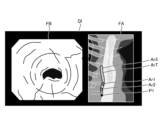
- the image processing unit 406 when the thermal treatment is completed by the thermal treatment device 5, the image processing unit 406 generates a display image DI shown in FIG. Specifically, as can be determined from position P1, the display image DI has been completed with the thermal treatment up to the bottom of the treatment target range ArT in Fig. 14, and therefore is an image in which at least one of the thermal denaturation insufficient region Ar1, the thermal denaturation excessive region Ar2, and the thermal denaturation adequate region Ar3 exists throughout the treatment target range ArT.
- the thermal denaturation insufficient region Ar1, the thermal denaturation excessive region Ar2, and the thermal denaturation adequate region Ar3 exist throughout the entire treatment target range ArT.
- the thermal denaturation insufficient region Ar1 is represented by a hollow circle
- the thermal denaturation excessive region Ar2 is represented by a dotted circle
- the thermal denaturation adequate region Ar3 is represented by diagonal lines.
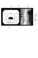
- the user after completing the thermal treatment, the user, such as the surgeon, can return the tip of the insertion portion 21 to the position of the thermally insufficient region Ar1 while checking the position P1 in the tissue image FA in the display image DI displayed on the display device 3, and can confirm the thermally insufficient region Ar1 in the thermally insufficient region FB, as shown in FIG. 15.
- the control device 4 acquires range information indicating the tissue image FA and the treatment target range ArT.
- the control device 4 also determines the state of thermal denaturation caused by the thermal treatment based on the fluorescence image.
- the control device 4 then causes the notification unit to notify thermal denaturation information indicating the state of thermal denaturation within the treatment target range ArT.
- the control device 4 displays a superimposed image in which the thermal denaturation information is superimposed on the tissue image FA on the display device 3, which is the notification unit. Therefore, according to the control device 4 of this embodiment, it is possible to allow a user such as an surgeon to determine whether or not thermal treatment was performed appropriately over the entire wide treatment target range ArT, thereby improving convenience.
- the control device 4 of this embodiment extracts a thermally insufficient region Ar1, a thermally excessive region Ar2, and an adequate thermal denaturation region Ar3 based on the fluorescence intensity of each pixel in the fluorescence image. Therefore, the state of thermal denaturation caused by the heat treatment can be determined simply and accurately.
- the medical device according to the present invention is mounted on an endoscope system used in endoscopic esophageal myotomy (POEM), but the present invention is not limited to this and may be mounted on an endoscope system used in other procedures, such as inferior turbinate mucosa cauterization for allergic rhinitis and blood cyst cauterization for endometriosis.
- POEM endoscopic esophageal myotomy
- the medical device according to the present invention is mounted on an endoscope system using a flexible endoscope, but the present invention is not limited to this and may also be mounted on an endoscope system using a rigid endoscope or an endoscope system using a medical surgery robot.
- the display device 3 is used as the notification unit according to the present invention, but this is not limited to this.
- the notification unit according to the present invention in addition to a configuration that notifies by displaying an image, other configurations such as a speaker that notifies by sound may also be used.
- thermal denaturation information indicating the state of thermal denaturation within the treatment target range ArT is displayed by superimposing a thermal denaturation-deficient region Ar1, a thermal denaturation-excessive region Ar2, and a thermal denaturation-adequate region Ar3 on a tissue image FA including the treatment target range ArT, but this is not limited to this.
- a thermal denaturation image FB is displayed without displaying the tissue image FA itself.
- the tissue image FA which is a tomographic image captured by a tomography apparatus, is used as the tissue image according to the present invention, but the present invention is not limited to this.
- an image hereinafter referred to as a concatenated image
- endoscopic images observation images (white light images)
- SLAM Simultaneous Localization and Mapping
- the tissue image according to the present invention may be a two-dimensional image or a three-dimensional image.
- the control device 4 calculated the three-dimensional coordinates of the position of the tip of the insertion portion 21 (tip portion 24) by using the configuration of the TOF sensor, the sensor unit 209, and the receiving unit 411 included in the imaging element 204, but this is not limited to this.
- the configuration of the above-mentioned TOF sensor, sensor unit 209, and receiving unit 411 may be omitted, and a configuration may be adopted in which the control device 4 calculates the three-dimensional coordinates of the position of the tip of the insertion portion 21 from the above-mentioned combined image.
- the control device 4 acquires (extracts) range information indicating the treatment target range ArT in the tissue image FA by image recognition using the learning model recorded in the learning model recording unit 408b, but this is not limited to this.
- the control device 4 may be configured to display a tissue image FA on the display device 3, while a user such as a surgeon operates the input unit 407 to acquire a range selected from within the tissue image FA as the treatment target range ArT.
Landscapes
- Health & Medical Sciences (AREA)
- Life Sciences & Earth Sciences (AREA)
- Surgery (AREA)
- Engineering & Computer Science (AREA)
- Biomedical Technology (AREA)
- Heart & Thoracic Surgery (AREA)
- Pathology (AREA)
- Radiology & Medical Imaging (AREA)
- Nuclear Medicine, Radiotherapy & Molecular Imaging (AREA)
- Biophysics (AREA)
- Physics & Mathematics (AREA)
- Optics & Photonics (AREA)
- Medical Informatics (AREA)
- Molecular Biology (AREA)
- Animal Behavior & Ethology (AREA)
- General Health & Medical Sciences (AREA)
- Public Health (AREA)
- Veterinary Medicine (AREA)
- Signal Processing (AREA)
- Endoscopes (AREA)
Abstract
Description
本発明は、医療用装置、内視鏡システム、制御方法、及び制御プログラムに関する。 The present invention relates to a medical device, an endoscope system, a control method, and a control program.
従来、エネルギデバイス等による生体組織への熱処置時における当該生体組織の熱変性の状態を可視化する技術が知られている(例えば、特許文献1参照)。
特許文献1に記載の技術では、生体組織に対する励起光の照射によって当該生体組織から発生した蛍光を撮像した撮像画像に基づいて、当該生体組織の熱変性の状態を可視化している。具体的に、特許文献1に記載の技術では、当該撮像画像の全画素のうち、蛍光強度が予め設定された蛍光強度よりも高い領域を熱変性が高い領域として表示する。
2. Description of the Related Art Conventionally, there is known a technique for visualizing the state of thermal denaturation of biological tissue during thermal treatment of the biological tissue by an energy device or the like (see, for example, Patent Document 1).
In the technology described in
ところで、例えば内視鏡的食道筋層切開術(POEM:Per-Oral Endoscopic Myotomy)等の手術方法では、エネルギデバイス等による生体組織への熱処置の処置対象範囲が比較的に広い範囲となる。このため、術者等のユーザは、当該広い範囲の処置対象範囲の全てにおいて、適切に熱処置を行うことができたか否かを判断することが難しい。
ここで、特許文献1に記載の技術を適用した場合には、生体組織における熱変性の状態を可視化することはできるが、上述した広い範囲の処置対象範囲の全てにおいて、適切に熱処置を行うことができたか否かを術者等のユーザに判断させることは難しい。
そこで、上述した広い範囲の処置対象範囲の全てにおいて、適切に熱処置を行うことができたか否かを術者等のユーザに判断させることができ、利便性を向上させることができる技術が要望されている。
However, in a surgical method such as Per-Oral Endoscopic Myotomy (POEM), the treatment area of the biological tissue to be treated by the heat treatment using the energy device is relatively large, making it difficult for a user such as a surgeon to determine whether the heat treatment has been properly performed over the entire treatment area.
Here, when the technology described in
Therefore, there is a demand for technology that can improve convenience by allowing a user such as a surgeon to determine whether or not thermal treatment was performed appropriately in all of the wide treatment target ranges described above.
本発明は、上記に鑑みてなされたものであって、利便性を向上させることができる医療用装置、内視鏡システム、制御方法、及び制御プログラムを提供することを目的とする。 The present invention has been made in consideration of the above, and aims to provide a medical device, an endoscope system, a control method, and a control program that can improve convenience.
上述した課題を解決し、目的を達成するために、本発明に係る医療用装置は、生体組織に対する励起光の照射によって前記生体組織から発生した蛍光を撮像した撮像画像を処理するプロセッサを備え、前記プロセッサは、前記生体組織における熱処置の対象部位を含む組織画像を取得し、前記組織画像における前記熱処置の処置対象範囲を示す範囲情報を取得し、前記撮像画像に基づいて、前記熱処置による熱変性の状態を判断し、前記処置対象範囲内における前記熱変性の状態を示す熱変性情報を報知部から報知させる。 In order to solve the above problems and achieve the objective, the medical device of the present invention includes a processor that processes captured images of fluorescence generated from biological tissue by irradiating the biological tissue with excitation light, and the processor acquires a tissue image including a target area of thermal treatment in the biological tissue, acquires range information in the tissue image that indicates the treatment range of the thermal treatment, determines the state of thermal denaturation caused by the thermal treatment based on the captured image, and causes an alarm unit to notify thermal denaturation information indicating the state of the thermal denaturation within the treatment range.
本発明に係る内視鏡システムは、励起光を照射する光源装置と、被検体内に挿入可能とし、前記被検体内の生体組織に対する前記励起光の照射によって前記生体組織から発生した蛍光を撮像した撮像画像を出力する内視鏡と、前記撮像画像を処理するプロセッサを有する医療用装置と、を備え、前記プロセッサは、前記生体組織における熱処置の対象部位を含む組織画像を取得し、前記組織画像における前記熱処置の処置対象範囲を示す範囲情報を取得し、前記撮像画像に基づいて、前記熱処置による熱変性の状態を判断し、前記処置対象範囲内における前記熱変性の状態を示す熱変性情報を報知部から報知させる。 The endoscope system according to the present invention comprises a light source device that irradiates excitation light, an endoscope that can be inserted into a subject and outputs an image of fluorescence generated from biological tissue in the subject by irradiating the biological tissue with the excitation light, and a medical device having a processor that processes the image, and the processor acquires a tissue image including a target site of thermal treatment in the biological tissue, acquires range information in the tissue image that indicates the treatment range of the thermal treatment, determines the state of thermal denaturation caused by the thermal treatment based on the image, and causes an alarm unit to notify the thermal denaturation information indicating the state of the thermal denaturation within the treatment range.
本発明に係る制御方法は、医療用装置が実行する制御方法であって、生体組織における熱処置の対象部位を含む組織画像を取得し、前記組織画像における前記熱処置の処置対象範囲を示す範囲情報を取得し、前記生体組織に対する励起光の照射によって前記生体組織から発生した蛍光を撮像した撮像画像に基づいて、前記熱処置による熱変性の状態を判断し、前記処置対象範囲内における前記熱変性の状態を示す熱変性情報を報知部から報知させる。 The control method according to the present invention is a control method executed by a medical device, which acquires a tissue image including a target area of a thermal treatment in biological tissue, acquires range information in the tissue image indicating a treatment range of the thermal treatment, determines a state of thermal denaturation caused by the thermal treatment based on an image of fluorescence generated from the biological tissue by irradiating the biological tissue with excitation light, and causes an alarm unit to notify thermal denaturation information indicating the state of the thermal denaturation within the treatment range.
本発明に係る制御プログラムは、医療用装置に実行させる制御プログラムであって、前記制御プログラムは、前記医療用装置に以下の実行を指示する:生体組織における熱処置の対象部位を含む組織画像を取得し、前記組織画像における前記熱処置の処置対象範囲を示す範囲情報を取得し、前記生体組織に対する励起光の照射によって前記生体組織から発生した蛍光を撮像した撮像画像に基づいて、前記熱処置による熱変性の状態を判断し、前記処置対象範囲内における前記熱変性の状態を示す熱変性情報を報知部から報知させる。 The control program according to the present invention is a control program executed by a medical device, and the control program instructs the medical device to perform the following: acquire a tissue image including a target area of thermal treatment in biological tissue, acquire range information in the tissue image indicating the treatment range of the thermal treatment, determine the state of thermal denaturation caused by the thermal treatment based on an image of fluorescence generated from the biological tissue by irradiating the biological tissue with excitation light, and cause an alarm unit to notify thermal denaturation information indicating the state of the thermal denaturation within the treatment range.
本発明に係る医療用装置、内視鏡システム、制御方法、及び制御プログラムによれば、利便性を向上させることができる。 The medical device, endoscope system, control method, and control program of the present invention can improve convenience.
以下に、図面を参照しつつ、本発明を実施するための形態(以下、実施の形態)について説明する。なお、以下に説明する実施の形態によって本発明が限定されるものではない。さらに、図面の記載において、同一の部分には同一の符号を付している。 Below, a mode for carrying out the present invention (hereinafter, "embodiment") will be described with reference to the drawings. Note that the present invention is not limited to the embodiment described below. Furthermore, in the drawings, the same parts are given the same reference numerals.
〔内視鏡システムの全体構成〕
図1は、実施の形態に係る内視鏡システム1の全体構成を示す図である。
本実施の形態に係る内視鏡システム1は、内視鏡的食道筋層切開術(POEM)において用いられる内視鏡システムである。具体的に、内視鏡的食道筋層切開術では、内視鏡2の挿入部21を被検体の口から食道へ挿入することによって当該被検体内を撮像し、当該撮像した画像データに基づく表示画像を表示装置3に表示する。そして、術者は、当該表示画像を確認しながら、熱処置装置5によって過剰に発達した食道及び噴門の筋肉を切開(熱処置)する。
この内視鏡システム1は、図1に示すように、内視鏡2と、表示装置3と、制御装置4と、熱処置装置5とを備える。
[Overall configuration of endoscope system]
FIG. 1 is a diagram showing an overall configuration of an
The
As shown in FIG. 1, the
内視鏡2は、被検体内を撮像した画像データ(RAWデータ)を生成し、当該画像データを制御装置4へ出力する。この内視鏡2は、図1に示すように、挿入部21と、操作部22と、ユニバーサルコード23とを備える。
挿入部21は、少なくとも一部が可撓性を有し、被検体内に挿入される。この挿入部21は、図1に示すように、当該挿入部21の先端に設けられた先端部24と、当該先端部24の基端側(操作部22側)に連結され、湾曲可能に構成された湾曲部25と、当該湾曲部25の基端側に連結され、可撓性を有する長尺状の可撓管部26とを備える。
The
The
操作部22は、挿入部21における基端部分に対して接続されている。そして、操作部22は、内視鏡2に対する各種の操作を受け付ける。この操作部22には、図1に示すように、湾曲ノブ221と、挿入口222と、複数の操作部材223とが設けられている。
湾曲ノブ221は、術者等のユーザによるユーザ操作に応じて回動可能に構成されている。そして、湾曲ノブ221は、回動することによって、挿入部21内に配設された金属製または樹脂製のワイヤ等の湾曲機構(図示略)を動作させる。これによって、湾曲部25は、湾曲する。
The
The
挿入口222は、挿入部21の先端から延在した管路である処置具チャンネル(図示略)に連通し、内視鏡2の外部から当該処置具チャンネルに対して処置具等を挿通するための挿入口である。
複数の操作部材223は、術者等のユーザによる各種操作を受け付けるボタン等によって構成され、ユニバーサルコード23を経由することによって、当該各種操作に応じた操作信号を制御装置4へ出力する。当該各種操作としては、内視鏡システム1の観察モードを通常光観察モード、蛍光観察モード、または、特定観察モードに切り替える操作等を例示することができる。
The
The
ユニバーサルコード23は、操作部22から挿入部21の延在方向とは異なる方向に延在し、光ファイバ等によって構成されたライトガイド231(図2参照)、及び、上述した画像データを伝送する第1の信号線232(図2参照)、上述した操作信号等を伝送する第2の信号線233(図2参照)等が配設されたコードである。そして、ユニバーサルコード23の基端には、図1に示すように、第1,第2のコネクタ部27,28と、ケーブル27aとが設けられている。
第1のコネクタ部27は、制御装置4に対して着脱自在に接続される。
ケーブル27aは、第1のコネクタ部27から延在するコイル状のケーブルである。
第2のコネクタ部28は、ケーブル27aの先端に設けられ、制御装置4に対して着脱自在に接続される。
The
The
The
The
表示装置3は、液晶または有機EL(Electro Luminescence)等の表示モニタによって構成され、制御装置4による制御の下、当該制御装置4において画像処理が施された画像データに基づく表示画像、及び内視鏡システム1に関する各種情報を表示する。
The
制御装置4は、本発明に係る医療用装置に相当する。この制御装置4は、GPU(Graphics Processing Unit)、FPGA(Field Programmable Gate Array)、またはCPU(Central Processing Unit)等のハードウェアを有する処理装置であるプロセッサと、当該プロセッサが使用する一時的な記憶域であるメモリを用いて実現される。そして、制御装置4は、メモリに記録されたプログラムに従って、内視鏡システム1の各部の動作を統括的に制御する。
The
熱処置装置5は、例えば、生体組織に対して高周波電流を供給することによって当該生体組織を熱処置する高周波ナイフ等のエネルギデバイス、または、生体組織に対して高出力赤外レーザを照射することによって当該生体組織を熱処置するレーザ照射装置等である。具体的に、熱処置装置5は、挿入口222から、挿入部21内の処置具チャンネルを経由することによって、食道へ挿入される。そして、熱処置装置5は、術者等のユーザによるユーザ操作に応じて、食道及び噴門の筋肉に対して熱処置を行う。
The
〔内視鏡システムの要部の機能構成〕
次に、上述した内視鏡システム1の要部の機能構成について説明する。
図2は、内視鏡システム1の要部の機能構成を示すブロック図である。
以下では、内視鏡2及び制御装置4の順に説明する。
[Functional configuration of main parts of endoscope system]
Next, the functional configuration of the main parts of the above-mentioned
FIG. 2 is a block diagram showing the functional configuration of the main parts of the
In the following, the
〔内視鏡の構成〕
先ず、内視鏡2の構成について説明する。
内視鏡2は、図2に示すように、照明光学系201と、撮像光学系202と、カットフィルタ203と、撮像素子204と、A/D変換部205と、P/S変換部206と、撮像記録部207と、撮像制御部208と、センサ部209とを備える。
ここで、照明光学系201、撮像光学系202、カットフィルタ203、撮像素子204、A/D変換部205、P/S変換部206、撮像記録部207、撮像制御部208、及びセンサ部209の各々は、先端部24内に配置されている。
[Configuration of the endoscope]
First, the configuration of the
As shown in FIG. 2 , the
Here, each of the illumination
照明光学系201は、1または複数のレンズ等によって構成され、ライトガイド231から供給された照明光を被写体に向けて照射する。
撮像光学系202は、1または複数のレンズ等によって構成され、被写体から反射された反射光、当該被写体からの戻り光、当該被写体が発光した蛍光等の光を集光することによって被写体像を撮像素子204の受光面上に結像する。
カットフィルタ203は、撮像光学系202の光軸L1上において、当該撮像光学系202と撮像素子204との間に配置される。そして、カットフィルタ203は、所定の波長帯域の光を遮光し、その他の光を透過する。
なお、カットフィルタ203の透過特性については、後述する「制御装置の構成」において説明する。
The illumination
The imaging
The
The transmission characteristics of the
撮像素子204は、2次元マトリクス状に配置されてなる複数の画素の各々に、ベイヤー配列(RGGB)を構成するカラーフィルタのいずれか1つが配置されてなるCCD(Charge Coupled Device)またはCMOS(Complementary Metal Oxide Semiconductor)のイメージセンサを用いて構成される。そして、撮像素子204は、撮像制御部208による制御の下、撮像光学系202によって結像された被写体像であって、カットフィルタ203を経由した被写体像を受光し、光電変換を行って撮像画像(アナログ信号)を生成する。本実施の形態では、撮像素子204は、当該イメージセンサとTOF(Time Of Flight)方式で被写体距離情報(以下、デプスマップ情報と記載)を取得するTOFセンサとが一体的に構成されたものである。当該デプスマップ情報とは、撮像素子204の位置(先端部24の位置)から撮像画像における画素位置に対応する観察対象上の対応位置までの被写体距離が画素位置毎に検出された情報である。
なお、デプスマップ情報を生成する構成としては、上述したTOFセンサに限らず、位相差センサまたはステレオカメラ等を採用しても構わない。
以下では、デプスマップ情報及び撮像画像を纏めて画像データと記載する。
そして、撮像素子204は、画像データをA/D変換部205へ出力する。
The
The configuration for generating the depth map information is not limited to the above-mentioned TOF sensor, but may also employ a phase difference sensor, a stereo camera, or the like.
Hereinafter, the depth map information and the captured image will be collectively referred to as image data.
Then, the
A/D変換部205は、A/D変換回路等を用いて構成され、撮像制御部208による制御の下、撮像素子204から入力されたアナログの画像データに対してA/D変換処理を行い、P/S変換部206へ出力する。
The A/
P/S変換部206は、P/S変換回路等を用いて構成され、撮像制御部208による制御の下、A/D変換部205から入力されたデジタルの画像データをパラレル/シリアル変換を行い、第1の信号線232を経由することによって制御装置4へ出力する。
なお、P/S変換部206の代わりに、画像データを光信号に変換するE/O変換部を設け、当該光信号によって制御装置4へ画像データを出力する構成としてもよい。また、例えばWi-Fi(Wireless Fidelity)(登録商標)等の無線通信によって画像データを制御装置4へ送信する構成としても構わない。
The P/
Note that, instead of the P/
撮像記録部207は、不揮発性メモリや揮発性メモリによって構成され、内視鏡2に関する各種情報(例えば撮像素子204の画素情報、カットフィルタ203の特性)を記録する。また、撮像記録部207は、第2の信号線233を経由することによって制御装置4から伝送されてくる各種設定データ及び制御用のパラメータを記録する。
The imaging and
撮像制御部208は、TG(Timing Generator)と、CPU等のハードウェアを有する処理装置であるプロセッサと、当該プロセッサが使用する一時的な記憶域であるメモリを用いて実現される。そして、撮像制御部208は、第2の信号線233を経由することによって制御装置4から受信した設定データに基づいて、撮像素子204、A/D変換部205、及びP/S変換部206の各々の動作を制御する。
The
センサ部209は、挿入部21の先端(先端部24)の位置、及び当該挿入部21の先端が向いている方向(当該先端の撮影視野)を算出するために用いられるセンサである。本実施の形態では、センサ部209は、磁気を発生する複数の磁気コイルによって構成されている。
The
〔制御装置の構成〕
次に、制御装置4の構成について説明する。
制御装置4は、図2に示すように、集光レンズ401と、第1の光源部402と、第2の光源部403と、光源制御部404と、S/P変換部405と、画像処理部406と、入力部407と、記録部408と、制御部409と、通信部410と、受信部411とを備える。
集光レンズ401は、第1,第2の光源部402,403の各々が発光した光を集光し、ライトガイド231へ出射する。
[Configuration of the control device]
Next, the configuration of the
As shown in FIG. 2, the
The
第1の光源部402は、光源制御部404による制御の下、可視光である白色光(通常光)を発光することによってライトガイド231へ当該白色光を照明光として供給する。この第1の光源部402は、コリメートレンズ、白色LED(Light Emitting Diode)ランプ、及び駆動ドライバ等を用いて構成される。
なお、第1の光源部402としては、赤色LEDランプ、緑色LEDランプ、及び青色LEDランプを用いて同時に発光することによって可視光の白色光を供給しても構わない。また、第1の光源部402としては、ハロゲンランプやキセノンランプ等によって構成しても構わない。
The first
The first
第2の光源部403は、光源制御部404による制御の下、所定の波長帯域を有する励起光を発光することによってライトガイド231へ当該励起光を照明光として供給する。
図3は、第2の光源部403が発光する励起光の波長特性を示す図である。具体的に、図3において、横軸が波長(nm)を示し、縦軸が波長特性を示す。また、図3において、曲線LVが第2の光源部403が発光する励起光の波長特性を示す。さらに、図3において、曲線LBが青色の波長帯域を示し、曲線LGが緑色の波長帯域を示し、曲線LRが赤色の波長帯域を示す。
本実施の形態では、第2の光源部403は、図3に示すように、中心波長(ピーク波長)が415nmであり、波長帯域が400nm~430nmである励起光を発光する。この第2の光源部403は、コリメートレンズ、紫色LD(laser Diode)等の半導体レーザ、及び駆動ドライバ等を用いて構成される。
The second
Fig. 3 is a diagram showing wavelength characteristics of the excitation light emitted by the second
In this embodiment, the second
ここで、カットフィルタ203の透過特性について説明する。
図4は、カットフィルタ203の透過特性を示す図である。具体的に、図4において、横軸が波長(nm)を示し、縦軸が波長特性を示す。また、図4において、曲線LFがカットフィルタ203の透過特性を示し、曲線LVが励起光の波長特性を示す。さらに、図4において、曲線LNGが生体組織への熱処置によって生じる終末糖化産物に対して励起光を照射することによって生じる蛍光の波長特性を示す。
本実施の形態では、カットフィルタ203は、図4に示すように、観察領域の生体組織から反射された励起光の一部を遮光し、蛍光成分を含む他の波長帯域の光を透過する。より具体的に、カットフィルタ203は、励起光を含む400nm~430nm未満の短波長側の波長帯域の光の一部を遮光し、かつ、熱処置によって生じる終末糖化産物に対して励起光を照射することによって生じる蛍光を含む430nmよりも長波長側の波長帯域の光を透過する。
Here, the transmission characteristics of the
Fig. 4 is a diagram showing the transmission characteristics of the
In this embodiment, the
光源制御部404は、FPGAまたはCPU等のハードウェアを有する処理装置であるプロセッサと、当該プロセッサが使用する一時的な記憶域であるメモリを用いて実現される。そして、光源制御部404は、制御部409から入力される制御データに基づいて、第1,第2の光源部402,403の各々の発光タイミング及び発光時間等を制御する。
The light
S/P変換部405は、制御部409による制御の下、第1の信号線232を経由することによって内視鏡2から受信した画像データに対してシリアル/パラレル変換を行い、画像処理部406へ出力する。
なお、内視鏡2が光信号で画像データを出力する場合、S/P変換部405の代わりに、光信号を電気信号に変換するO/E変換部を設けても構わない。また、内視鏡2が無線通信によって画像データを送信する場合、S/P変換部405の代わりに、無線信号を受信可能な通信モジュールを設けても構わない。
Under the control of the
When the
画像処理部406は、本発明に係るプロセッサに相当する。この画像処理部406は、GPUまたはFPGA等のハードウェアを有する処理装置であるプロセッサと、当該プロセッサが使用する一時的な記憶域であるメモリを用いて実現される。そして、画像処理部406は、制御部409による制御の下、S/P変換部405から入力されたパラレルデータの画像データに所定の画像処理を施し、表示装置3へ出力する。ここで、所定の画像処理としては、デモザイク処理、ホワイトバランス処理、ゲイン調整処理、γ補正処理、及びフォーマット変換処理等を例示することができる。
The
入力部407は、マウス、フットスイッチ、キーボード、ボタン、スイッチ、及びタッチパネル等を用いて構成され、術者等のユーザによるユーザ操作を受け付け、当該ユーザ操作に応じた操作信号を制御部409へ出力する。
The
記録部408は、揮発性メモリ、不揮発性メモリ、SSD(Solid State Drive)及びHDD(Hard Disk Drive)等やメモリカード等の記録媒体を用いて構成される。そして、記録部408は、内視鏡システム1の動作に必要な各種パラメータ等を含むデータを記録する。また、記録部408は、内視鏡システム1を動作させるための各種プログラムを記録するプログラム記録部408aと、以下に示す学習モデル記録部408bとを備える。
The
学習モデル記録部408bは、制御部409が行う画像認識で用いられる学習モデルを記録する。当該学習モデルは、例えば人工知能(AI(Artificial Intelligence))を用いた機械学習によって生成されたモデルである。
具体的に、当該学習モデルは、内視鏡的食道筋層切開術(POEM)での熱処置の処置対象範囲を撮像した画像データを教師データとし、当該教師データに基づいて当該処置対象範囲を機械学習(例えば深層学習等)することによって得られたモデルである。
The learning
Specifically, the learning model is a model obtained by using image data captured of the treatment area of thermal treatment during endoscopic esophageal myotomy (POEM) as training data, and using machine learning (e.g., deep learning) to learn the treatment area based on the training data.
制御部409は、本発明に係るプロセッサに相当する。この制御部409は、FPGAまたはCPU等のハードウェアを有する処理装置であるプロセッサと、当該プロセッサが使用する一時的な記憶域であるメモリを用いて実現される。そして、制御部409は、内視鏡システム1を構成する各部を統括的に制御する。
The
通信部410は、外部のCT(Computed Tomography)またはMRI(Magnetic Resonance Imaging)等の断層撮影装置(図示略)との間で各種データの通信を所定のプロトコルに従って行うインターフェースである。そして、通信部410は、制御部409による制御の下、断層撮影装置によって撮影された断層画像である組織画像を取得する。
なお、通信部410と外部の断層撮影装置との間での通信は、無線通信としてもよく、あるいは有線通信としても構わない。また、断層撮影装置によって撮影された断層画像(組織画像)をサーバ等に記憶させておき、通信部410が当該サーバから当該断層画像(組織画像)を取得する構成を採用しても構わない。
The
The communication between the
受信部411は、センサ部209から発せられる磁気を受信する。そして、受信部411は、当該受信した磁気に応じた信号を制御部409へ出力する。
The
〔内視鏡システムの観察モードにおける観察原理〕
次に、内視鏡システム1の観察モードにおける観察原理について説明する。
以下では、蛍光観察モード及び通常光観察モードの順に説明する。
[Observation principle in the observation mode of the endoscope system]
Next, the observation principle in the observation mode of the
The following description will be given in the order of the fluorescent observation mode and the normal light observation mode.
〔蛍光観察モードにおける観察原理〕
先ず、蛍光観察モードにおける観察原理について説明する。
図5は、蛍光観察モードにおける観察原理を説明する図である。
図5のグラフG11に示すように、先ず、制御装置4は、第2の光源部403を発光させることによって、励起光(中心波長415nm)を生体組織O10に照射する。この場合、図5のグラフG12に示すように、少なくとも生体組織O10で反射された励起光の成分及び戻り光を含む反射光(以下、反射光W10と記載)は、カットフィルタ203によって遮光され強度が低下する一方、当該遮光する波長帯域よりも長波長側の成分の一部は強度を落とさずに撮像素子204に入射する。
[Observation principle in fluorescence observation mode]
First, the observation principle in the fluorescence observation mode will be described.
FIG. 5 is a diagram for explaining the observation principle in the fluorescent observation mode.
As shown in graph G11 of Fig. 5, first, the
より具体的には、図5のグラフG12に示すように、カットフィルタ203は、撮像素子204におけるG画素に入射する反射光W10であって、励起光の波長帯域を含む短波長側の波長帯域の反射光W10の大部分を遮光し、当該遮光する波長帯域よりも長波長側の波長帯域を透過する。また、図5のグラフG12に示すように、カットフィルタ203は、生体組織O10への熱処置によって生じた終末糖化産物が自家発光した蛍光WF10を透過する。このため、撮像素子204におけるR画素、G画素、及びB画素の各々には、強度が低下した反射光W10と、蛍光WF10とが入射する。
ここで、撮像素子204におけるG画素は、蛍光WF10に感度を有する。しかしながら、図5のグラフG12における蛍光特性の曲線LNGに示すように、蛍光が微小な反応である。このため、G画素における蛍光WF10に応じた出力値は、小さい値となる。
More specifically, as shown in graph G12 of Fig. 5, the
Here, the G pixel in the
その後、画像処理部406は、撮像素子204から画像データ(RAWデータ)を取得し、当該画像データに含まれるG画素及びB画素の各々の出力値に対して画像処理を行い、蛍光画像を生成する。この場合において、G画素の出力値には、生体組織O10への熱処置がなされた熱処置領域(終末糖化産物)から発せされた蛍光WF10に応じた蛍光情報が含まれる。また、B画素の出力値には、熱処置領域を含む被検体の生体組織O10からの背景情報が含まれる。そして、当該蛍光画像を表示装置3に表示させれば、生体組織O10への熱処置がなされた熱処置領域を観察することが可能となる。
Then, the
〔通常光観察モードにおける観察原理〕
次に、通常光観察モードにおける観察原理について説明する。
図6は、通常光観察モードにおける観察原理を説明する図である。
図6のグラフG21に示すように、先ず、制御装置4は、第1の光源部402を発光させることによって、白色光を生体組織O10に照射する。この場合、生体組織O10で反射された反射光及び戻り光(以下、反射光WR30,WG30,WB30と記載)は、一部がカットフィルタ203によって遮光され、残りが撮像素子204に入射する。具体的には、図6のグラフG22に示すように、カットフィルタ203は、励起光の波長帯域を含む短波長側の波長帯域の反射光を遮光する。このため、撮像素子204におけるB画素に入射する青色の波長帯域の光の成分が、カットフィルタ203を配置していない状態と比べて小さくなる。
[Observation principle in normal light observation mode]
Next, the observation principle in the normal light observation mode will be described.
FIG. 6 is a diagram for explaining the observation principle in the normal light observation mode.
As shown in graph G21 of Fig. 6, first, the
その後、画像処理部406は、撮像素子204から画像データ(RAWデータ)を取得し、当該画像データに含まれるR画素、G画素、及びB画素の各々の出力値に対して画像処理を行い、観察画像(白色光画像)を生成する。この場合において、画像処理部406は、画像データに含まれる青色成分がカットフィルタ203を配置していない状態と比べて小さいため、赤色成分、緑色成分、及び青色成分の比率が一定となるようにホワイトバランスを調整するホワイトバランス調整処理を行う。そして、当該観察画像(白色光画像)を表示装置3に表示させれば、カットフィルタ203を配置している場合であっても、自然な観察画像(白色光画像)を観察することが可能となる。
Then, the
〔制御方法〕
次に、制御装置4が実行する制御方法について説明する。
以下では、熱処置装置5によって生体組織に対して熱処置を行う前に制御装置4が実行する制御方法(以下、熱処置前の制御方法と記載)と、当該熱処置を行う際に制御装置4が実行する制御方法(以下、熱処置を行う際の制御方法と記載)とを順に説明する。
[Control method]
Next, a control method executed by the
Below, we will explain in order the control method executed by the
〔熱処置前の制御方法〕
先ず、熱処置装置5によって生体組織に対して熱処置を行う前に制御装置4が実行する制御方法について説明する。
図7は、熱処置前の制御方法を示すフローチャートである。図8及び図9は、熱処置前の制御方法を説明する図である。具体的に、図8は、ステップS1Aにおいて取得された組織画像FAを示す図である。図9は、図8に対応した図であって、ステップS1Cを説明する図である。
[Control method before heat treatment]
First, a control method executed by the
Fig. 7 is a flow chart showing a control method before heat treatment. Fig. 8 and Fig. 9 are diagrams explaining the control method before heat treatment. Specifically, Fig. 8 is a diagram showing a tissue image FA acquired in step S1A. Fig. 9 is a diagram corresponding to Fig. 8 and explaining step S1C.
制御部409は、ユーザによる入力部407への操作に応じて、通信部410の動作を制御し、当該通信部410を経由することによって、外部の断層撮影装置から組織画像FA(図8)を取得する(ステップS1A)。
ここで、組織画像FAは、熱処置装置5によって熱処置を行う対象となる被検体と同一の被検体が外部の断層撮影装置によって撮影された断層画像である。ここで、組織画像FAには、画素毎に、画素位置に対応する観察対象上の対応位置の3次元座標が付されている。当該3次元座標は、特定の座標系を基準とした座標であって、断層撮影装置によって算出されたものである。
The
Here, the tissue image FA is a tomographic image captured by an external tomographic device of the same subject as the subject to be thermally treated by the
ステップS1Aの後、制御部409は、組織画像FAにおける熱処置の処置対象範囲を示す範囲情報を取得する(ステップS1B)。
具体的に、制御部409は、ステップS1Bにおいて、学習モデル記録部408bに記録された学習モデルを用いた画像認識によって、組織画像FAにおける熱処置の処置対象範囲ArT(図9)を示す範囲情報を取得(抽出)する。
After step S1A, the
Specifically, in step S1B, the
ステップS1Bの後、画像処理部406は、制御部409による制御の下、図9に示すように、組織画像FAに対して処置対象範囲ArTを重畳する(ステップS1C)。そして、制御部409は、処置対象範囲ArTが重畳された組織画像FAのデータを記録部408に記録する。
以上のステップS1A~S1Cによって、熱処置前の制御方法が完了する。
After step S1B, the
The above steps S1A to S1C complete the control method before heat treatment.
〔熱処置を行う際の制御方法〕
次に、熱処置装置5によって生体組織に対して熱処置を行う際に制御装置4が実行する制御方法について説明する。
図10は、熱処置を行う際の制御方法を示すフローチャートである。図11ないし図15は、熱処置を行う際の制御方法を説明する図である。具体的に、図11は、生体組織における終末糖化産物が自家発光した蛍光の蛍光強度と、当該生体組織への熱処置による侵襲度(深度及び領域)との相関関係(直線LY)を示す図である。なお、図11において、縦軸が蛍光強度を示し、横軸が生体組織への熱処置による侵襲度を示している。図12は、図8及び図9に対応した図であって、ステップS2Bにおいて生成される表示画像DIを示す図である。図13ないし図15は、図12に対応した図であって、ステップS2D~S2Hを説明する図である。
[Control method when carrying out heat treatment]
Next, a control method executed by the
FIG. 10 is a flow chart showing a control method when performing heat treatment. FIG. 11 to FIG. 15 are diagrams for explaining a control method when performing heat treatment. Specifically, FIG. 11 is a diagram showing a correlation (straight line L Y ) between the fluorescence intensity of the fluorescence auto-emitted by advanced glycation endproducts in the biological tissue and the invasiveness (depth and area) of the thermal treatment to the biological tissue. In FIG. 11, the vertical axis shows the fluorescence intensity, and the horizontal axis shows the invasiveness of the thermal treatment to the biological tissue. FIG. 12 is a diagram corresponding to FIG. 8 and FIG. 9, and shows a display image DI generated in step S2B. FIG. 13 to FIG. 15 are diagrams corresponding to FIG. 12, and show steps S2D to S2H.
なお、内視鏡システム1は、既に以下の状態に設定されているものである。
すなわち、挿入部21が被検体の口から食道に挿入され、内視鏡システム1の観察領域は、当該食道内の領域となっている。また、熱処置装置5は、挿入口222から、挿入部21内の処置具チャンネルを経由することによって食道内に挿入され、熱処置可能な状態となっている。さらに、術者等のユーザによる操作部材223への「内視鏡システム1の観察モードを特定観察モードに切り替える」操作に応じて、当該観察モードが特定観察モードに切り替えられているものとする。
The
That is, the
先ず、画像処理部406は、制御部409による制御の下、生体組織における熱変性した熱変性領域Ar1~Ar3を識別可能とする熱変性画像FB(図12~図15)を生成する(ステップS2A)。ここで、熱変性領域Ar1は、熱変性が不足している熱変性不足領域である。また、熱変性領域Ar2は、熱変性が過剰な熱変性過剰領域である。さらに、熱変性領域Ar3は、熱変性が適切な熱変性適切領域である。なお、図13ないし図15では、説明の便宜上、熱変性画像FBにおいて、熱変性適切領域Ar3の図示を省略している。
First, under the control of the
具体的に、特定観察モードでは、蛍光観察モードと通常光観察モードとを交互に切り替えることによって、蛍光画像と観察画像(白色光画像)とを時分割で生成する。そして、画像処理部406は、ステップS2Aにおいて、蛍光画像と略同一のタイミングで生成された観察画像(白色光画像)とを重畳することによって熱変性画像FBを生成する重畳処理を実行する。
Specifically, in the specific observation mode, the fluorescence image and the observation image (white light image) are generated in a time-division manner by alternately switching between the fluorescence observation mode and the normal light observation mode. Then, in step S2A, the
ここで、画像処理部406が実行する重畳処理としては、以下に示す第1,第2の重畳処理を例示することができる。
第1の重畳処理は、観察画像(白色光画像)において、蛍光画像における熱変性領域Ar1~Ar3と同一の画素位置となる領域を当該蛍光画像における当該熱変性領域Ar1~Ar3の画像に置き換える処理である。
第2の重畳処理は、蛍光画像の熱変性領域Ar1~Ar3における各画素位置の蛍光強度に応じて、観察画像(白色光画像)における熱変性領域Ar1~Ar3と同一の画素位置となる領域の各画素に付す蛍光を示す色の明るさを変更する処理(所謂アルファブレンド処理)である。
Here, examples of the superimposition processing executed by the
The first superposition process is a process of replacing areas in the observation image (white light image) that are at the same pixel positions as the thermally altered regions Ar1 to Ar3 in the fluorescence image with images of the thermally altered regions Ar1 to Ar3 in the fluorescence image.
The second superposition process is a process (so-called alpha blending process) that changes the brightness of the color indicating the fluorescence applied to each pixel in the area that is at the same pixel position as the thermally denatured regions Ar1 to Ar3 in the observation image (white light image) depending on the fluorescence intensity at each pixel position in the thermally denatured regions Ar1 to Ar3 of the fluorescence image.
ステップS2Aの後、画像処理部406は、ステップS1Cにおいて記録部408に記録された組織画像FAのデータを読み出し、図12に示すように、当該組織画像FAと、ステップS2Aにおいて生成した熱変性画像FBとを並べた表示画像DIを生成する(ステップS2B)。
After step S2A, the
ステップS2Bの後、制御部409は、組織画像FAと熱変性画像FBとの画素毎の対応関係を特定する特定処理を開始する(ステップS2C)。
具体的に、制御部409は、ステップS2Cにおいて、センサ部209から発せられ、受信部411によって受信された磁気に基づいて、挿入部21の形状を推定するとともに、当該挿入部21の先端(先端部24)の位置の3次元座標を示す位置情報、及び当該先端の撮影視野を示す方向情報とを算出する。当該3次元座標は、組織画像FAにおける画素毎に付された3次元座標と同一の座標系での座標である。また、制御部409は、算出した位置情報及び方向情報と、熱変性画像FBの生成に用いられた画像データに含まれるデプスマップ情報とに基づいて、当該熱変性画像FBの画素毎に、画素位置に対応する観察対象上の対応位置の3次元座標を算出する。そして、制御部409は、組織画像FAにおける画素毎に付された3次元座標と、熱変性画像FBにおける画素毎に算出した3次元座標とを比較し、当該組織画像FAと当該熱変性画像FBとの画素毎の対応関係を特定する特定処理を開始する。また、当該特定処理の結果に基づいて、画像処理部406は、制御部409による制御の下、図12に示すように、表示画像DIにおける組織画像FAに対して、熱変性画像FBの被写体であって、現在、内視鏡2によって観察している領域の位置に対応する当該組織画像FA上の位置P1を重畳する。
After step S2B, the
Specifically, in step S2C, the
ステップS2Cの後、制御部409は、報知制御を実行する(ステップS2D)。
具体的に、制御部409は、ステップS2Dにおいて、画像処理部406の動作を制御し、図12に示す表示画像DIを表示装置3に表示させる。すなわち、表示装置3は、本発明に係る報知部に相当する。
After step S2C, the
Specifically, in step S2D, the
ところで、生体組織における終末糖化産物が自家発光した蛍光の蛍光強度と、当該生体組織への熱処置による侵襲度(熱変性の高さ)とは、図11に示すように、相関関係がある。具体的に、図11の直線LYに示すように、蛍光強度は、熱変性の高さが高いほど(生体組織への熱処置による侵襲度が大きいほど)、高くなる。
そして、術者等のユーザは、処置対象範囲ArT内における熱変性不足領域Ar1や熱変性過剰領域Ar2を認識することができれば、その対策を施すことによって、術後の再発や穿孔のリスクを低減することができる。そこで、本実施の形態では、以下に示すステップS2E~S2Hを実行することによって、処置対象範囲ArT内における熱変性不足領域Ar1や熱変性過剰領域Ar2を術者等のユーザに認識させる。
Incidentally, there is a correlation between the intensity of fluorescence auto-emitted by advanced glycation endproducts in biological tissue and the degree of invasiveness of thermal treatment of the biological tissue (degree of thermal denaturation) as shown in Fig. 11. Specifically, as shown by the straight lines L -Y in Fig. 11, the higher the degree of thermal denaturation (the greater the invasiveness of thermal treatment of the biological tissue), the higher the fluorescence intensity.
If a user such as a surgeon can recognize the thermally insufficient region Ar1 and the thermally excessive region Ar2 within the treatment target range ArT, the user can take measures to reduce the risk of postoperative recurrence and perforation. Therefore, in this embodiment, the following steps S2E to S2H are executed to allow a user such as a surgeon to recognize the thermally insufficient region Ar1 and the thermally excessive region Ar2 within the treatment target range ArT.
具体的に、画像処理部406は、熱変性画像FBの生成に用いた蛍光画像の全画素のうち、蛍光強度が第1の蛍光強度Th1(図11)以下の画素によって構成された領域を熱変性不足領域Ar1として抽出する(ステップS2E)。
また、画像処理部406は、熱変性画像FBの生成に用いた蛍光画像の全画素のうち、蛍光強度が第1の蛍光強度Th1よりも大きい第2の蛍光強度Th2(図11)以上の画素によって構成された領域を熱変性過剰領域Ar2として抽出する(ステップS2F)。
さらに、画像処理部406は、熱変性画像FBの生成に用いた蛍光画像の全画素のうち、蛍光強度が第1の蛍光強度Th1よりも大きく、第2の蛍光強度Th2よりも小さい画素によって構成された領域を熱変性適切領域Ar3として抽出する(ステップS2G)。
なお、ステップS2E~S2Gは、ステップS2E~S2Gの順に実行されてもよく、他の順で実行されてもよく、あるいは、並列に略同時に実行されても構わない。
Specifically, the
In addition, the
Furthermore, the
Note that steps S2E to S2G may be executed in the order of steps S2E to S2G, or in another order, or may be executed in parallel and substantially simultaneously.
ここで、ステップS2E~S2Gにおいて用いられる蛍光強度としては、撮像素子204におけるG画素の出力値、当該撮像素子204から取得した画像データへのデモザイク後の各画素の画素値(r,g,b)の少なくともg値、または、Y信号(輝度信号)に応じた輝度値等を例示することができる。
Here, examples of the fluorescence intensity used in steps S2E to S2G include the output value of the G pixel in the
そして、画像処理部406は、表示画像DIを更新する(ステップS2H)。この後、制御装置4は、ステップS2Dに戻る。
具体的に、画像処理部406は、ステップS2Hにおいて、制御部409による制御の下、特定処理の結果に基づいて、以下の処理を実行する。
すなわち、画像処理部406は、表示画像DIにおける組織画像FAに対して、ステップS2Eにて抽出した蛍光画像上の熱変性不足領域Ar1に対応する組織画像FA上の熱変性不足領域Ar1、ステップS2Fにて抽出した蛍光画像上の熱変性過剰領域Ar2に対応する組織画像FA上の熱変性過剰領域Ar2、及びステップS2Gにおいて抽出した蛍光画像上の熱変性適切領域Ar3に対応する組織画像FA上の熱変性適切領域Ar3を重畳する。すなわち、熱変性不足領域Ar1、熱変性過剰領域Ar2、及び熱変性適切領域Ar3は、本発明に係る熱変性情報に相当する。
Then, the
Specifically, in step S2H, the
That is, the
以上説明したステップS2D~S2Hを繰り返し実行することによって、画像処理部406によって生成される表示画像DIは、以下に示すように変更される。
先ず、熱処置装置5によって熱処置を行う前の状態では、画像処理部406は、図12に示す表示画像DIを生成する。
具体的に、当該表示画像DIは、位置P1から判断される通り、熱処置が行われていないため、処置対象範囲ArTに熱変性不足領域Ar1、熱変性過剰領域Ar2、及び熱変性適切領域Ar3が存在しない画像となっている。
By repeatedly executing steps S2D to S2H described above, the display image DI generated by the
First, in a state before thermal treatment is performed by the
Specifically, as can be judged from position P1, no thermal treatment has been performed in the display image DI, and therefore the image does not include the insufficient thermal denaturation area Ar1, the excessive thermal denaturation area Ar2, and the adequate thermal denaturation area Ar3 in the treatment target range ArT.
また、熱処置装置5によって熱処置を行っていくと、画像処理部406は、図13に示す表示画像DIを生成する。
具体的に、当該表示画像DIは、位置P1から判断される通り、処置対象範囲ArTの図13中、最上部から下方に向けて途中まで熱処置を行っているため、当該処置対象範囲ArTの途中までに熱変性不足領域Ar1、熱変性過剰領域Ar2、及び熱変性適切領域Ar3の少なくともいずれかが存在する画像となっている。なお、図13の例では、当該途中までに熱変性適切領域Ar3のみが存在している。
As the thermal treatment is performed by the
Specifically, as can be determined from position P1, the displayed image DI shows that the thermal treatment is performed from the top of the treatment target area ArT downwards to partway through the treatment target area ArT in Fig. 13, and therefore at least one of the thermally insufficient area Ar1, the thermally excessive area Ar2, and the thermally adequate area Ar3 exists partway through the treatment target area ArT. Note that in the example of Fig. 13, only the thermally adequate area Ar3 exists partway through.
そして、熱処置装置5によって熱処置を完了した状態では、画像処理部406は、図14に示す表示画像DIを生成する。
具体的に、当該表示画像DIは、位置P1から判断される通り、処置対象範囲ArTの図14中、最下部まで熱処置を完了しているため、当該処置対象範囲ArTの全体に熱変性不足領域Ar1、熱変性過剰領域Ar2、及び熱変性適切領域Ar3の少なくともいずれかが存在する画像となっている。なお、図14の例では、当該全体に熱変性不足領域Ar1、熱変性過剰領域Ar2、及び熱変性適切領域Ar3が存在している。図14では、熱変性不足領域Ar1を白抜きの円で表現し、熱変性過剰領域Ar2をドット付きの円で表現し、熱変性適切領域Ar3を斜線によって表現している。
Then, when the thermal treatment is completed by the
Specifically, as can be determined from position P1, the display image DI has been completed with the thermal treatment up to the bottom of the treatment target range ArT in Fig. 14, and therefore is an image in which at least one of the thermal denaturation insufficient region Ar1, the thermal denaturation excessive region Ar2, and the thermal denaturation adequate region Ar3 exists throughout the treatment target range ArT. Note that in the example of Fig. 14, the thermal denaturation insufficient region Ar1, the thermal denaturation excessive region Ar2, and the thermal denaturation adequate region Ar3 exist throughout the entire treatment target range ArT. In Fig. 14, the thermal denaturation insufficient region Ar1 is represented by a hollow circle, the thermal denaturation excessive region Ar2 is represented by a dotted circle, and the thermal denaturation adequate region Ar3 is represented by diagonal lines.
また、例えば、術者等のユーザは、熱処置を完了した後、表示装置3に表示された表示画像DIにおける組織画像FA内の位置P1を確認しながら、挿入部21の先端を熱変性不足領域Ar1の位置まで戻せば、図15に示すように、熱変性画像FBによって当該熱変性不足領域Ar1を確認することができる。
Furthermore, for example, after completing the thermal treatment, the user, such as the surgeon, can return the tip of the
以上説明した本実施の形態によれば、以下の効果を奏する。
本実施の形態に係る制御装置4は、組織画像FA及び処置対象範囲ArTを示す範囲情報を取得する。また、制御装置4は、蛍光画像に基づいて、熱処置による熱変性の状態を判断する。そして、制御装置4は、処置対象範囲ArT内における熱変性の状態を示す熱変性情報を報知部から報知させる。本実施の形態では、制御装置4は、組織画像FAに対して熱変性情報を重畳した重畳画像を当該報知部である表示装置3に表示する。
したがって、本実施の形態に係る制御装置4によれば、広い範囲の処置対象範囲ArTの全てにおいて、適切に熱処置を行うことができたか否かを術者等のユーザに判断させることができ、利便性を向上させることができる。
According to the present embodiment described above, the following effects are achieved.
The
Therefore, according to the
また、本実施の形態に係る制御装置4は、熱処置による熱変性の状態を判断する際、蛍光画像における画素毎の蛍光強度に基づいて、熱変性不足領域Ar1、熱変性過剰領域Ar2、及び熱変性適切領域Ar3を抽出する。
このため、熱処置による熱変性の状態を簡単に、かつ精度良く判断することができる。
In addition, when determining the state of thermal denaturation due to heat treatment, the
Therefore, the state of thermal denaturation caused by the heat treatment can be determined simply and accurately.
(その他の実施形態)
ここまで、本発明を実施するための形態を説明してきたが、本発明は上述した実施の形態によってのみ限定されるべきものではない。
上述した実施の形態では、本発明に係る医療用装置を内視鏡的食道筋層切開術(POEM)において用いられる内視鏡システムに搭載していたが、これに限らず、その他の手技、例えば、アレルギー性鼻炎に対する下鼻甲介粘膜焼灼や、子宮内膜症に対する血液嚢胞焼灼において用いられる内視鏡システムに搭載しても構わない。
Other Embodiments
Although the embodiments for carrying out the present invention have been described above, the present invention should not be limited to the above-described embodiments.
In the above-described embodiment, the medical device according to the present invention is mounted on an endoscope system used in endoscopic esophageal myotomy (POEM), but the present invention is not limited to this and may be mounted on an endoscope system used in other procedures, such as inferior turbinate mucosa cauterization for allergic rhinitis and blood cyst cauterization for endometriosis.
上述した実施の形態では、本発明に係る医療用装置を軟性の内視鏡を用いた内視鏡システムに搭載していたが、これに限らず、硬性の内視鏡を用いた内視鏡システム、医療用手術ロボットを用いた内視鏡システムに搭載しても構わない。 In the above-described embodiment, the medical device according to the present invention is mounted on an endoscope system using a flexible endoscope, but the present invention is not limited to this and may also be mounted on an endoscope system using a rigid endoscope or an endoscope system using a medical surgery robot.
上述した実施の形態では、本発明に係る報知部として、表示装置3を採用していたが、これに限らない。本発明に係る報知部としては、画像を表示することによって報知する構成の他、音声によって報知するスピーカ等の他の構成を採用しても構わない。
In the above-described embodiment, the
上述した実施の形態では、処置対象範囲ArTを含む組織画像FAに対して、熱変性不足領域Ar1、熱変性過剰領域Ar2、及び熱変性適切領域Ar3を重畳することによって、当該処置対象範囲ArT内における熱変性の状態を示す熱変性情報を表示していたが、これに限らない。
例えば、組織画像FA自体を表示せずに、熱変性画像FBのみを表示する。そして、処置対象範囲ArTの熱処置が完了した場合に、当該処置対象範囲ArTの熱処置が適切に完了したことを示す熱変性情報、または、当該処置対象範囲ArT内に熱変性不足領域Ar1や熱変性過剰領域Ar2が存在することを示す熱変性情報を報知(画像や文字等の表示、音声による報知等)する構成を採用しても構わない。
In the above-described embodiment, thermal denaturation information indicating the state of thermal denaturation within the treatment target range ArT is displayed by superimposing a thermal denaturation-deficient region Ar1, a thermal denaturation-excessive region Ar2, and a thermal denaturation-adequate region Ar3 on a tissue image FA including the treatment target range ArT, but this is not limited to this.
For example, only the thermal denaturation image FB is displayed without displaying the tissue image FA itself. Then, when the thermal treatment of the treatment target range ArT is completed, a configuration may be adopted in which thermal denaturation information indicating that the thermal treatment of the treatment target range ArT has been properly completed, or thermal denaturation information indicating that a thermal denaturation-insufficient region Ar1 or a thermal denaturation-excessive region Ar2 exists within the treatment target range ArT, is notified (by display of an image or text, by voice, or the like).
上述した実施の形態では、本発明に係る組織画像として、断層撮影装置によって撮影された断層画像である組織画像FAを採用していたが、これに限らない。
例えば、SLAM(Simultaneous Localization and Mapping)技術を利用し、内視鏡2によって撮像された内視鏡画像(観察画像(白色光画像))を連結することによって生成された画像(以下、連結画像と記載)を本発明に係る組織画像として採用しても構わない。
また、本発明に係る組織画像としては、2次元画像であってもよく、あるいは、3次元画像であっても構わない。
In the above-described embodiment, the tissue image FA, which is a tomographic image captured by a tomography apparatus, is used as the tissue image according to the present invention, but the present invention is not limited to this.
For example, an image (hereinafter referred to as a concatenated image) generated by concatenating endoscopic images (observation images (white light images)) captured by the
Furthermore, the tissue image according to the present invention may be a two-dimensional image or a three-dimensional image.
上述した実施の形態では、制御装置4は、撮像素子204に含まれるTOFセンサ、センサ部209、及び受信部411の構成を用いることによって、挿入部21の先端(先端部24)の位置の3次元座標を算出していたが、これに限らない。
例えば、上述したTOFセンサ、センサ部209、及び受信部411の構成を省略し、制御装置4が上述した連結画像から挿入部21の先端の位置の3次元座標を算出する構成を採用しても構わない。
In the above-described embodiment, the
For example, the configuration of the above-mentioned TOF sensor,
上述した実施の形態では、制御装置4は、学習モデル記録部408bに記録された学習モデルを用いた画像認識によって、組織画像FAにおける処置対象範囲ArTを示す範囲情報を取得(抽出)していたが、これに限らない。
例えば、制御装置4は、組織画像FAを表示装置3に表示させながら、術者等のユーザによる入力部407への操作によって当該組織画像FA内から選択された範囲を処置対象範囲ArTとして取得する構成を採用しても構わない。
In the above-described embodiment, the
For example, the
1 内視鏡システム
2 内視鏡
3 表示装置
4 制御装置
5 熱処置装置
21 挿入部
22 操作部
23 ユニバーサルコード
24 先端部
25 湾曲部
26 可撓管部
27 第1のコネクタ部
27a ケーブル
28 第2のコネクタ部
201 照明光学系
202 撮像光学系
203 カットフィルタ
204 撮像素子
205 A/D変換部
206 P/S変換部
207 撮像記録部
208 撮像制御部
209 センサ部
221 湾曲ノブ
222 挿入口
223 操作部材
231 ライトガイド
232 第1の信号線
233 第2の信号線
401 集光レンズ
402 第1の光源部
403 第2の光源部
404 光源制御部
405 S/P変換部
406 画像処理部
407 入力部
408 記録部
408a プログラム記録部
408b 学習モデル記録部
409 制御部
410 通信部
411 受信部
Ar1 熱変性不足領域
Ar2 熱変性過剰領域
Ar3 熱変性適切領域
ArT 処置対象範囲
DI 表示画像
FA 組織画像
FB 熱変性画像
G11~G13,G21~G23 グラフ
L1 光軸
LB,LG,LR,LV 曲線
LF カットフィルタの透過特性
LNG 蛍光の波長特性
LY 直線
O10 生体組織
P1 位置
Th1 第1の蛍光強度
Th2 第2の蛍光強度
W10,WB30,WG30,WR30 反射光
WF10 蛍光
LIST OF
Claims (12)
前記プロセッサは、
前記生体組織における熱処置の対象部位を含む組織画像を取得し、
前記組織画像における前記熱処置の処置対象範囲を示す範囲情報を取得し、
前記撮像画像に基づいて、前記熱処置による熱変性の状態を判断し、
前記処置対象範囲内における前記熱変性の状態を示す熱変性情報を報知部から報知させる医療用装置。 a processor for processing an image of fluorescence generated from a biological tissue by irradiating the biological tissue with excitation light;
The processor,
acquiring a tissue image including a target site of the thermal treatment in the biological tissue;
acquiring range information indicating a treatment target range of the thermal treatment in the tissue image;
determining a state of thermal denaturation caused by the heat treatment based on the captured image;
A medical device that notifies, from an alarm unit, thermal denaturation information indicating the state of the thermal denaturation within the treatment target area.
画像を表示する表示部であり、
前記プロセッサは、
前記組織画像に対して前記熱変性情報を重畳した重畳画像を前記表示部に表示させる請求項1に記載の医療用装置。 The notification unit is
a display unit for displaying an image;
The processor,
The medical device according to claim 1 , wherein a superimposed image in which the thermal denaturation information is superimposed on the tissue image is displayed on the display unit.
前記生体組織に対して前記熱処置を施すことによって生じる終末糖化産物から発生する請求項1に記載の医療用装置。 The fluorescence is
The medical device according to claim 1 , which is generated from advanced glycation end products produced by subjecting the biological tissue to the heat treatment.
前記撮像画像における画素毎の蛍光強度に基づいて、前記熱処置による熱変性の状態を判断する請求項1に記載の医療用装置。 The processor,
The medical device according to claim 1 , wherein the state of thermal denaturation caused by the heat treatment is determined based on the fluorescence intensity for each pixel in the captured image.
前記撮像画像の全画素のうち、蛍光強度が第1の蛍光強度以下の画素によって構成される領域を前記熱処置による熱変性が不足している熱変性不足領域として特定し、
前記処置対象範囲内における前記熱変性不足領域を示す前記熱変性情報を前記報知部から報知させる請求項4に記載の医療用装置。 The processor,
identifying a region constituted by pixels having a fluorescence intensity equal to or lower than a first fluorescence intensity among all pixels of the captured image as a thermal denaturation insufficient region in which thermal denaturation by the heat treatment is insufficient;
The medical device according to claim 4 , wherein the thermal denaturation information indicating the thermal denaturation insufficient area within the treatment target area is notified from the notification unit.
前記撮像画像の全画素のうち、蛍光強度が前記第1の蛍光強度よりも高い第2の蛍光強度以上の画素によって構成される領域を前記熱処置による熱変性が過剰な熱変性過剰領域として特定し、
前記処置対象範囲内における前記熱変性過剰領域を示す前記熱変性情報を前記報知部から報知させる請求項5に記載の医療用装置。 The processor,
Identifying a region constituted by pixels having a fluorescent intensity equal to or higher than a second fluorescent intensity that is higher than the first fluorescent intensity among all pixels of the captured image as a thermally excessively denatured region in which thermal denaturation due to the heat treatment is excessive;
The medical device according to claim 5 , wherein the thermal denaturation information indicating the excessive thermal denaturation region within the treatment target area is notified from the notification unit.
断層撮影装置によって撮影された断層画像、または、超音波観測装置によって生成された超音波画像である請求項1に記載の医療用装置。 The tissue image is
2. The medical device according to claim 1, wherein the image is a tomographic image taken by a tomography device or an ultrasonic image generated by an ultrasonic observation device.
内視鏡によって撮影された内視鏡画像を連結することによって生成された画像である請求項1に記載の医療用装置。 The tissue image is
2. The medical device according to claim 1, wherein the image is generated by connecting endoscopic images captured by an endoscope.
被検体内に挿入される挿入部を有する内視鏡によって撮影された内視鏡画像であり、
前記プロセッサは、
前記挿入部の先端の位置を示す位置情報、前記先端の撮影視野を示す方向情報、及び前記撮像画像に基づいて、前記撮像画像における被写体の3次元座標を算出し、前記3次元座標に基づいて、前記組織画像と前記撮像画像との画素毎の対応関係を特定する請求項1に記載の医療用装置。 The captured image is
An endoscopic image captured by an endoscope having an insertion portion that is inserted into a subject,
The processor,
2. The medical device according to claim 1, wherein the three-dimensional coordinates of a subject in the captured image are calculated based on position information indicating a position of the tip of the insertion portion, directional information indicating a field of view of the tip, and the captured image, and the correspondence between the tissue image and the captured image for each pixel is determined based on the three-dimensional coordinates.
被検体内に挿入可能とし、前記被検体内の生体組織に対する前記励起光の照射によって前記生体組織から発生した蛍光を撮像した撮像画像を出力する内視鏡と、
前記撮像画像を処理するプロセッサを有する医療用装置と、を備え、
前記プロセッサは、
前記生体組織における熱処置の対象部位を含む組織画像を取得し、
前記組織画像における前記熱処置の処置対象範囲を示す範囲情報を取得し、
前記撮像画像に基づいて、前記熱処置による熱変性の状態を判断し、
前記処置対象範囲内における前記熱変性の状態を示す熱変性情報を報知部から報知させる内視鏡システム。 A light source device that irradiates excitation light;
an endoscope that can be inserted into a subject and outputs an image obtained by capturing fluorescence generated from living tissue in the subject by irradiating the living tissue with the excitation light;
A medical device having a processor for processing the captured image,
The processor,
acquiring a tissue image including a target site of the thermal treatment in the biological tissue;
acquiring range information indicating a treatment target range of the thermal treatment in the tissue image;
determining a state of thermal denaturation caused by the heat treatment based on the captured image;
An endoscope system that causes a notification unit to notify thermal denaturation information indicating a state of the thermal denaturation within the treatment target area.
生体組織における熱処置の対象部位を含む組織画像を取得し、
前記組織画像における前記熱処置の処置対象範囲を示す範囲情報を取得し、
前記生体組織に対する励起光の照射によって前記生体組織から発生した蛍光を撮像した撮像画像に基づいて、前記熱処置による熱変性の状態を判断し、
前記処置対象範囲内における前記熱変性の状態を示す熱変性情報を報知部から報知させる制御方法。 A control method executed by a medical device, comprising:
Acquire a tissue image including a target portion of the thermal treatment in the biological tissue;
acquiring range information indicating a treatment target range of the thermal treatment in the tissue image;
determining a state of thermal denaturation caused by the heat treatment based on an image of fluorescence generated from the biological tissue by irradiating the biological tissue with excitation light;
A control method for causing an alarm unit to notify thermal denaturation information indicating the state of the thermal denaturation within the treatment target area.
前記制御プログラムは、前記医療用装置に以下の実行を指示する:
生体組織における熱処置の対象部位を含む組織画像を取得し、
前記組織画像における前記熱処置の処置対象範囲を示す範囲情報を取得し、
前記生体組織に対する励起光の照射によって前記生体組織から発生した蛍光を撮像した撮像画像に基づいて、前記熱処置による熱変性の状態を判断し、
前記処置対象範囲内における前記熱変性の状態を示す熱変性情報を報知部から報知させる制御プログラム。 A control program to be executed by a medical device,
The control program instructs the medical device to:
Acquire a tissue image including a target portion of the thermal treatment in the biological tissue;
acquiring range information indicating a treatment target range of the thermal treatment in the tissue image;
determining a state of thermal denaturation caused by the heat treatment based on an image of fluorescence generated from the biological tissue by irradiating the biological tissue with excitation light;
A control program that causes an alarm unit to notify thermal denaturation information indicating the state of the thermal denaturation within the treatment target area.
Priority Applications (3)
| Application Number | Priority Date | Filing Date | Title |
|---|---|---|---|
| PCT/JP2023/004407 WO2024166312A1 (en) | 2023-02-09 | 2023-02-09 | Medical device, endoscope system, control method, and control program |
| CN202380093073.7A CN120641017A (en) | 2023-02-09 | 2023-02-09 | Medical device, endoscope system, control method, and control program |
| US19/287,964 US20250352048A1 (en) | 2023-02-09 | 2025-08-01 | Medical device, endoscope system, control method, and computer-readable recording medium |
Applications Claiming Priority (1)
| Application Number | Priority Date | Filing Date | Title |
|---|---|---|---|
| PCT/JP2023/004407 WO2024166312A1 (en) | 2023-02-09 | 2023-02-09 | Medical device, endoscope system, control method, and control program |
Related Child Applications (1)
| Application Number | Title | Priority Date | Filing Date |
|---|---|---|---|
| US19/287,964 Continuation US20250352048A1 (en) | 2023-02-09 | 2025-08-01 | Medical device, endoscope system, control method, and computer-readable recording medium |
Publications (1)
| Publication Number | Publication Date |
|---|---|
| WO2024166312A1 true WO2024166312A1 (en) | 2024-08-15 |
Family
ID=92262240
Family Applications (1)
| Application Number | Title | Priority Date | Filing Date |
|---|---|---|---|
| PCT/JP2023/004407 Ceased WO2024166312A1 (en) | 2023-02-09 | 2023-02-09 | Medical device, endoscope system, control method, and control program |
Country Status (3)
| Country | Link |
|---|---|
| US (1) | US20250352048A1 (en) |
| CN (1) | CN120641017A (en) |
| WO (1) | WO2024166312A1 (en) |
Citations (4)
| Publication number | Priority date | Publication date | Assignee | Title |
|---|---|---|---|---|
| JP2007244746A (en) * | 2006-03-17 | 2007-09-27 | Olympus Medical Systems Corp | Observation system |
| JP2008142355A (en) * | 2006-12-11 | 2008-06-26 | Aloka Co Ltd | Image formation system |
| WO2020054723A1 (en) * | 2018-09-10 | 2020-03-19 | オリンパス株式会社 | Thermal insult observation device, endoscope system, thermal insult observation system, and thermal insult observation method |
| JP2021000258A (en) * | 2019-06-21 | 2021-01-07 | ソニー株式会社 | Medical observation system, medical observation method, and information processing device |
-
2023
- 2023-02-09 WO PCT/JP2023/004407 patent/WO2024166312A1/en not_active Ceased
- 2023-02-09 CN CN202380093073.7A patent/CN120641017A/en active Pending
-
2025
- 2025-08-01 US US19/287,964 patent/US20250352048A1/en active Pending
Patent Citations (4)
| Publication number | Priority date | Publication date | Assignee | Title |
|---|---|---|---|---|
| JP2007244746A (en) * | 2006-03-17 | 2007-09-27 | Olympus Medical Systems Corp | Observation system |
| JP2008142355A (en) * | 2006-12-11 | 2008-06-26 | Aloka Co Ltd | Image formation system |
| WO2020054723A1 (en) * | 2018-09-10 | 2020-03-19 | オリンパス株式会社 | Thermal insult observation device, endoscope system, thermal insult observation system, and thermal insult observation method |
| JP2021000258A (en) * | 2019-06-21 | 2021-01-07 | ソニー株式会社 | Medical observation system, medical observation method, and information processing device |
Also Published As
| Publication number | Publication date |
|---|---|
| CN120641017A (en) | 2025-09-12 |
| US20250352048A1 (en) | 2025-11-20 |
Similar Documents
| Publication | Publication Date | Title |
|---|---|---|
| JP5450527B2 (en) | Endoscope device | |
| JP2023010809A (en) | Medical image processing device, endoscope system, operating method and program for medical image processing device, recording medium | |
| US20230000330A1 (en) | Medical observation system, medical imaging device and imaging method | |
| JP6401800B2 (en) | Image processing apparatus, operation method of image processing apparatus, operation program for image processing apparatus, and endoscope apparatus | |
| US20230248209A1 (en) | Assistant device, endoscopic system, assistant method, and computer-readable recording medium | |
| JP6230409B2 (en) | Endoscope device | |
| JPWO2017115442A1 (en) | Image processing apparatus, image processing method, and image processing program | |
| US12121219B2 (en) | Medical image processing device, medical imaging device, medical observation system, image processing method, and computer-readable recording medium | |
| WO2024166312A1 (en) | Medical device, endoscope system, control method, and control program | |
| US20250359729A1 (en) | Medical device, medical system, learning device, operation method of medical device, and computer-readable recording medium | |
| US20250348985A1 (en) | Image processing apparatus, medical system, image processing apparatus operation method, and computer-readable recording medium | |
| US20250352032A1 (en) | Medical device, medical system, learning device, method of operating medical device, and computer-readable recording medium | |
| US20250352029A1 (en) | Medical device, medical system, operation method of medical device, and computer-readable recording medium | |
| US20250359726A1 (en) | Medical apparatus, medical system, control method, and computer-readable recording medium | |
| US20250352028A1 (en) | Medical device, medical system, learning device, method of operating medical device, and computer-readable recording medium | |
| CN120641018A (en) | Image processing device, medical system, working method of image processing device, and learning device | |
| US20250352026A1 (en) | Medical device, medical system, operation method of medical device, and computer-readable recording medium | |
| US20250356490A1 (en) | Assistance device, operation method of assistance device, computer-readable recording medium, medical system, and learning device | |
| WO2025234035A1 (en) | Medical device, endoscope system, control method, and control program | |
| CN120641029A (en) | Image processing device, medical system, working method of image processing device, and learning device | |
| CN120659570A (en) | Medical device, endoscope system, control method, control program, and learning device | |
| WO2024166309A1 (en) | Medical device, endoscope system, control method, control program, and learning device | |
| WO2017046876A1 (en) | Endoscope system, image processing apparatus, and image processing method |
Legal Events
| Date | Code | Title | Description |
|---|---|---|---|
| 121 | Ep: the epo has been informed by wipo that ep was designated in this application |
Ref document number: 23921143 Country of ref document: EP Kind code of ref document: A1 |
|
| WWE | Wipo information: entry into national phase |
Ref document number: 202380093073.7 Country of ref document: CN |
|
| NENP | Non-entry into the national phase |
Ref country code: DE |
|
| WWP | Wipo information: published in national office |
Ref document number: 202380093073.7 Country of ref document: CN |