WO2024166294A1 - 工作機械 - Google Patents
工作機械 Download PDFInfo
- Publication number
- WO2024166294A1 WO2024166294A1 PCT/JP2023/004367 JP2023004367W WO2024166294A1 WO 2024166294 A1 WO2024166294 A1 WO 2024166294A1 JP 2023004367 W JP2023004367 W JP 2023004367W WO 2024166294 A1 WO2024166294 A1 WO 2024166294A1
- Authority
- WO
- WIPO (PCT)
- Prior art keywords
- robot
- point
- control device
- upper limit
- lower limit
- Prior art date
- Legal status (The legal status is an assumption and is not a legal conclusion. Google has not performed a legal analysis and makes no representation as to the accuracy of the status listed.)
- Ceased
Links
Images



Classifications
-
- B—PERFORMING OPERATIONS; TRANSPORTING
- B23—MACHINE TOOLS; METAL-WORKING NOT OTHERWISE PROVIDED FOR
- B23Q—DETAILS, COMPONENTS, OR ACCESSORIES FOR MACHINE TOOLS, e.g. ARRANGEMENTS FOR COPYING OR CONTROLLING; MACHINE TOOLS IN GENERAL CHARACTERISED BY THE CONSTRUCTION OF PARTICULAR DETAILS OR COMPONENTS; COMBINATIONS OR ASSOCIATIONS OF METAL-WORKING MACHINES, NOT DIRECTED TO A PARTICULAR RESULT
- B23Q17/00—Arrangements for observing, indicating or measuring on machine tools
-
- G—PHYSICS
- G05—CONTROLLING; REGULATING
- G05B—CONTROL OR REGULATING SYSTEMS IN GENERAL; FUNCTIONAL ELEMENTS OF SUCH SYSTEMS; MONITORING OR TESTING ARRANGEMENTS FOR SUCH SYSTEMS OR ELEMENTS
- G05B19/00—Program-control systems
- G05B19/02—Program-control systems electric
- G05B19/18—Numerical control [NC], i.e. automatically operating machines, in particular machine tools, e.g. in a manufacturing environment, so as to execute positioning, movement or co-ordinated operations by means of program data in numerical form
- G05B19/409—Numerical control [NC], i.e. automatically operating machines, in particular machine tools, e.g. in a manufacturing environment, so as to execute positioning, movement or co-ordinated operations by means of program data in numerical form characterised by using manual data input [MDI] or by using control panel, e.g. controlling functions with the panel; characterised by control panel details or by setting parameters
-
- G—PHYSICS
- G05—CONTROLLING; REGULATING
- G05B—CONTROL OR REGULATING SYSTEMS IN GENERAL; FUNCTIONAL ELEMENTS OF SUCH SYSTEMS; MONITORING OR TESTING ARRANGEMENTS FOR SUCH SYSTEMS OR ELEMENTS
- G05B19/00—Program-control systems
- G05B19/02—Program-control systems electric
- G05B19/42—Recording and playback systems, i.e. in which the program is recorded from a cycle of operations, e.g. the cycle of operations being manually controlled, after which this record is played back on the same machine
Definitions
- This disclosure relates to a machine tool that sets a detection range for detecting the movement of a robot.
- Patent Document 1 describes a machine tool that outputs a reference point signal when the tool of the robot returns to a reference point.
- the machine tool in Patent Document 1 sets a neighborhood area that includes coordinate points before and after the reference point, and outputs a reference point signal when the tool returns within this neighborhood area.
- the destination of a robot that transports a workpiece varies depending on the type of workpiece, the configuration of the machine tool, and other factors. For this reason, the coordinates of the destination set in the operation program that controls the robot vary depending on the type of workpiece, etc. If the coordinates of the destination are called robot points and managed on the machine tool side, then by associating coordinates set in a different operation program with the robot point, the coordinates can be changed from the operation panel of the machine tool, etc. If it is desired to detect movement to this robot point using a detection range that includes an arbitrary reference point as described in Patent Document 1 above, there is a risk of setting an incorrect detection range unless the relationship between the robot point and the detection range is correctly understood.
- This disclosure was made in consideration of the above problems, and aims to provide a machine tool that can reduce the occurrence of errors in setting the detection range for detecting movement to a robot point.
- this specification discloses a machine tool that includes a display device, a robot that transports a workpiece, and a control device that controls the movement of the robot, and the control device executes a movement process that moves the robot based on the coordinates of a robot point that is associated with a position to which the robot moves, a detection process that detects that the robot has moved to the robot point by setting a detection range from a lower limit position that is closer to the coordinate indicated by the robot point to an upper limit position that is further than the coordinate indicated by the robot point in the movement direction in which the robot moves in the movement process, and a display process that displays the robot point associated with the detection range indicated by the lower limit position and the upper limit position in correspondence with the input unit on a setting screen that displays an input unit for inputting setting values for the lower limit position and the upper limit position.
- the control device displays a setting screen that accepts the setting values for the robot point and the upper and lower limit positions of the detection range that detects movement to that robot point.
- the control device displays the robot point associated with the upper and lower limit positions in association with the input sections for those upper and lower limit positions. This makes it possible to determine which detection range (upper and lower limit positions) to change when changing the setting values by referring to the robot point information. This reduces the occurrence of errors in setting the detection range.
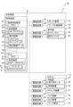
- FIG. 2 is a front view of the machine tool according to the present embodiment.
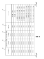
- FIG. 4 is a diagram showing data registered in point data.
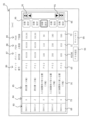
- FIG. 4 is a diagram showing data registered in detection range data.
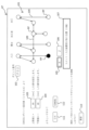
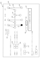
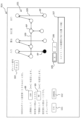
- FIG. FIG. FIG. 7 is a diagram showing the adjustment screen after a robot point different from that in FIG. 6 is selected.
- FIG. 7 is a diagram showing an adjustment screen after a Z-axis selection unit is operated in the state shown in FIG. 6 .
- FIG. 13 is a diagram showing a setting screen according to another embodiment.
- FIG. 1 is a front view of the machine tool 10 according to this embodiment.
- FIG. 2 is a block diagram of the machine tool 10.
- the machine tool 10 of this embodiment can be equipped with optional devices such as an entrance device 15, an exit device 17, and a workpiece placement table (hereinafter referred to as the "placement table") 18 in addition to the main unit 11 and the robot 13.
- FIG. 1 also shows some of the devices and equipment (such as the rail base 26) installed in each device in a transparent manner.
- the devices and equipment such as the rail base 26
- the left-right direction parallel to the installation surface 19 of the device and the machine width direction is referred to as the X-axis direction
- the front-rear direction parallel to the installation surface 19 of the device and perpendicular to the left-right direction is referred to as the Y-axis direction
- the up-down direction perpendicular to the X-axis direction and the Y-axis direction is referred to as the Z-axis direction, based on the direction of the machine tool 10 viewed from the front.
- the machine tool 10 is arranged in the following order from the right in the X-axis direction: an entrance device 15 for carrying in the workpiece W, a main body device 11, a table 18 on which the workpiece W is placed to check the machined workpiece W, and an exit device 17 for discharging the workpiece W.
- the main body device 11 includes, for example, a turret device 21 (see FIG. 2) and a workpiece spindle device 22 (see FIG. 2) therein, and processes the workpiece W chucked to the workpiece spindle device 22 with the tools (cutting tools, rotary tools, etc.) of the turret device 21.
- a sliding door 24 and an operation panel 25 are provided on the front side of the main body device 11.
- the operation panel 25 includes, for example, a touch panel 20 (see FIG. 2) and an operation switch 23 (see FIG. 2), and performs operations such as displaying information about the machine tool 10 and receiving operation instructions.
- the machine tool 10 accepts changes to the coordinates of the upper limit position and the lower limit position (upper limit value 71, lower limit value 72) described below via the touch panel 20 (see FIG. 4).
- the robot 13 transfers the workpiece W between the entrance device 15, the workpiece spindle device 22 of the main body device 11, the placement table 18, and the exit device 17.
- the robot 13 is, for example, a gantry-type workpiece transport device (which may also be called a loader), and moves the movable part 27 in the left-right direction along a rail base 26 provided on the upper part of the main body device 11.
- the robot 13 slides the movable part 27 in the X-axis direction, for example, by engaging a pinion fixed to the output shaft of a travel motor 28 (see FIG. 2) built into the movable part 27 with the teeth of a travel rack provided on the rail base 26.
- the robot 13 also includes a lifting device (such as a motor or rack mechanism) 29 (see FIG.
- a pair of chuck mechanisms 31 (see FIG. 2) are attached to the lower end of the movable part 27.
- Each of the pair of chuck mechanisms 31 has claws for clamping the workpiece W, and transfers the workpiece W between the pair of chuck mechanisms 31 and other devices.
- the destination or position of the chuck mechanisms 31 of the movable part 27 may be simply referred to as the destination or position of the robot 13.
- the robot 13 is an example of a robot of the present disclosure.
- the configuration of the robot 13 described above is one example.
- the axes along which the robot 13 (chuck mechanism 31) moves are not limited to the X-axis direction and the Z-axis direction.
- the axes along which the robot 13 moves may be, for example, three axial directions along the X-axis, Y-axis, and Z-axis.
- the axis along which the robot 13 moves is not limited to a slide axis (linear drive axis), but may be the so-called A-axis that rotates around the X-axis, the so-called B-axis that rotates around the Y-axis, or the so-called C-axis that rotates around the Z-axis. Therefore, a combination of various slide axes and rotation axes that move the robot 13 can be used as an axis that accepts changes in coordinates in the present disclosure.
- the entrance device 15 also includes a transfer device 32 that grips the workpiece W and moves left and right.
- the transfer device 32 can receive the workpiece W from, for example, a work stocker (not shown), a previous process device (not shown), a user, etc., at a receiving position provided behind the door 33.
- the transfer device 32 moves leftward from the receiving position and transfers the workpiece W to the robot 13 at the leftmost transfer position (the receiving position of the robot 13 in FIG. 3).
- the exit device 17 also includes a receiving device 35 that grips the workpiece W and moves left and right.
- the receiving device 35 receives the workpiece W from the robot 13 at the rightmost receiving position (the receiving position of the robot 13 in FIG. 3) moved rightward from the transfer position behind the door 36.
- the receiving device 35 moves leftward and transfers the workpiece W to a subsequent process device (not shown) or the like at the transfer position behind the receiving door 36.
- the stand 18 is provided on the left side of the main body 11, and the slide member 39 is exposed from an opening 38A of the fence 38.
- the temporarily placed workpiece W can be checked by pulling the slide member 39 downward toward the front side.
- the above-described configuration of the machine tool 10 is an example.
- the machine tool 10 may be equipped with a measuring device that measures the outer diameter of the workpiece W after machining, a cleaning device that cleans the workpiece W, etc.
- control device 41 Next, the control device 41 provided in the main unit 11 will be described with reference to Fig. 2.
- the machine tool 10 is provided with a plurality of drive circuits 43 that connect the control device 41 to each of the above-mentioned devices (robot 13, entrance device 15, exit device 17, table 18, turret device 21, workpiece spindle device 22, and operation panel 25).
- the connection configuration in the block diagram of Fig. 2 is one example.
- all of the drive circuits 43 connected to each device may be installed within the main unit 11.
- the control device 41 includes a numerical control device 45 and a PLC 46.
- the numerical control device 45 includes a CPU 47 and a storage device 48.
- the PLC 46 includes a CPU 51 and a storage device 52.
- the storage devices 48 and 52 include, for example, RAM, ROM, flash memory, etc.
- the configuration of the storage devices 48 and 52 is not limited to the above configuration, and may include an HDD or SSD, an external storage device such as a USB memory, a storage medium such as a DVD-RAM, or a combination of these.
- the storage device 48 stores a plurality of NC programs 53 that numerically control the operation of the robot 13, turret device 21, work spindle device 22, etc., when machining the workpiece W.
- the NC program 53 that controls the robot 13 will be described in particular. Therefore, in the following description, when the NC program 53 is written, it means the NC program 53 that controls the robot 13.
- the control device 41 is electrically connected to each of the above-mentioned devices via the drive circuit 43, and is capable of controlling each device.
- the drive circuit 43 is an amplifier circuit that amplifies the signal input from the operation panel 25.
- the drive circuit 43 is connected to a motor such as the spindle motor (not shown) of the work spindle device 22 or the travel motor 28 of the robot 13, the drive circuit 43 is a driver circuit (servo amplifier) that changes the power (such as three-phase AC current) supplied to each motor (such as a servo motor) based on the instruction signal (movement amount, destination position, moving speed, target torque, etc.) of the control device 41.
- the numerical control device 45 executes the NC program 53 in the CPU 47, and outputs an instruction signal to the drive circuit 43 (driver circuit) according to the numerical command described in the NC program 53 to control it.
- the drive circuit 43 executes feedback control to change the current of the three-phase AC based on, for example, encoder information from the encoders attached to each servo motor and an instruction signal from the control device 41, and notifies the numerical control device 45 of the completion of processing, etc.
- the control device 41 slides the robot 13 (chuck mechanism 31) along the X-axis and Z-axis to the desired position based on the numerical control by the numerical control device 45.
- the drive source for sliding each device is not limited to a servo motor, and other drive sources such as a stepping motor or linear motor can be used.
- PLC 46 is a programmable logic controller.
- a ladder program 58 for constructing a ladder circuit for processing various signals is stored in storage device 52.
- PLC 46 executes ladder program 58 in CPU 51, and executes, by sequence processing based on ladder program 58, a process of outputting an output signal to various elements such as lamps, relays, and solenoids provided in machine tool 10 to drive them, and a process of inputting an input signal from elements such as limit switches and sensors.
- PLC 46 is also connected to numerical control device 45 via communication bus 59, for example, and is capable of communicating with numerical control device 45.
- PLC 46 executes input and output of signals between numerical control device 45 and PLC 46 using device 61 constructed based on ladder program 58.
- Device 61 is, for example, a storage area constructed on storage device 52, and is referenced when CPU 51 executes ladder program 58.
- device 61 is a device that stores signal values of external I/O (sensors, etc.) equipped in machine tool 10, a device (G device or F device) that stores signal values for communication with numerical control device 45, a device that realizes a keep relay that stores setting values, etc.
- PLC 46 relays signals (input/output) between external I/O equipped in machine tool 10 and numerical control device 45.
- the storage device 48 also stores a display control program 55 for changing the display contents of the operation panel 25, point data 56, detection range data 57, and various other data required for processing (not shown).
- the display control program 55 is a program for changing the display contents of the touch panel 20 of the operation panel 25.
- the display control program 55 executes display processing and the like for displaying a screen (such as the setting screen 81 in FIG. 5) that accepts changes to the coordinate values registered in the point data 56 and the upper limit values 71 and lower limit values 72 (see FIG. 4) registered in the detection range data 57.
- FIG. 3 shows data registered in the point data 56.
- data related to a robot point RP is stored in the point data 56.
- a point number 63, a position 64, an X-axis coordinate 65, a Z-axis coordinate 66, a PSW number 67X of the X-axis coordinate, and a PSW number 67Z of the Z-axis coordinate are stored in association with one another.
- the point data 56 is, for example, a database that associates information such as the point number 63 as one record and stores a record for each robot point RP.
- Each record corresponds to a robot point RP to which the robot 13 (chuck mechanism 31) moves.
- the robot point RP is, for example, information that associates the position to which the robot 13 moves with coordinates.
- the robot point RP is not limited to information that associates a position with coordinates, but may be other information that associates coordinates with information that identifies those coordinates, such as information that associates a point number 63 with coordinates (X-axis coordinate 65, Z-axis coordinate 66).
- the point number 63 is an identification number that identifies the position 64, i.e., a number that can identify the robot point RP, and a unique number is set for each position 64.
- the point numbers 63 are set in ascending order from top to bottom in FIG. 3, P01, P02, P03, ....
- the control device 41 is capable of registering, for example, 50 robot points RP, from P01 to P50, of point numbers 63.
- the information that identifies the position 64 is not limited to numbers, but may also use letters such as the alphabet or a combination of these. The same applies to the PSW number 69, which will be described later.
- Position 64 is the position and name of the robot point RP indicated by point number 63.
- Position 64 is, for example, a position where the transfer of the workpiece W occurs, such as the original position (P01) that is the initial position of the robot 13, or the receiving position (P02) where the robot 13 receives the workpiece W from the entrance device 15.
- position 64 is a stopping position where the robot 13 stops to change the direction of movement, or a turning position where the orientation of the chuck mechanism 31 is changed. Therefore, various positions to which the robot 13 moves can be adopted as position 64.
- Position 64 may also be a point with no name set, such as "point 6", where the specific name of the destination of the robot 13 has not been determined.
- position 64 is the position when it moves in the rotation direction.
- the X-axis coordinate 65 is the coordinate in the X-axis direction of the robot point RP indicated by point number 63.
- the Z-axis coordinate 66 is the coordinate in the Z-axis direction of the robot point RP indicated by point number 63.
- the coordinates are, for example, absolute coordinates relative to a predetermined reference position of the machine tool 10.
- the unit of coordinates can be, for example, mm.
- the destination of the robot 13 will differ depending on the type of workpiece W and the configuration of the optional device. Therefore, the coordinates of the destination set in the NC program 53 will differ depending on the type of workpiece W and the optional device.
- the destinations of the robot 13 for various types of workpieces W and the configurations of optional devices can be almost covered by, for example, 50 types of robot points RP, it is effective to manage the robot points RP on the machine tool 10 side.
- the control device 41 displays a screen (not shown) for changing the X-axis coordinate 65 and Z-axis coordinate 66 based on a predetermined operation on the touch panel 20, for example, and accepts changes to the coordinates of each robot point RP.
- the coordinates of each robot point RP are associated with variables in the NC program 53. For this reason, the user can change the coordinates of the robot point RP in the NC program 53 by appropriately changing the coordinates of the robot point RP that the user wants to use.
- the numerical control device 45 of the control device 41 sets the coordinates of the robot point RP associated with the variables included in the NC program 53 according to the definition of the variables (rules for substituting the coordinates of the robot point RP into the variables) and executes the program.
- the numerical control device 45 sets the X-axis coordinate 65 of a predetermined point number 63 to a predetermined variable, and executes the G code with the variable as an argument.
- the NC program 53 of this embodiment different variables are set depending on the workpiece W to be machined.
- the robot point RP is associated with the variables.
- the control device 41 is capable of registering multiple robot points RP, and when executing the NC program 53, the coordinates of the robot point RP associated with the variables set in the NC program 53 are set as the variables and the NC program 53 is executed. This allows the user to change the coordinates set in the NC program 53 by changing the coordinates of the robot point RP on a change screen or the like.
- the X and Z coordinates registered as the robot point RP can be reflected in the NC program 53 and reflected in the actual movement of the robot 13.
- the position switch function is, for example, a function for detecting whether or not a moving object is present within a detection range from a specified lower limit position to an upper or lower position. In the moving direction of the object, a position before an arbitrary reference position is the lower limit position, and a position beyond the reference position is the upper limit position.
- the detection range is set as a range from the lower limit position to the upper limit position.
- the detection range is set with a specified robot point RP as the reference position, and the movement of the robot 13 to the specified robot point RP is detected using the detection range.
- the position switch function for example, the position switch function of FANUC Corporation can be adopted.
- FIG. 4 shows the data registered in detection range data 57.
- detection range data 57 stores data related to the position switch function.
- PSW number 69, upper limit value 71, lower limit value 72, axis direction 73, and comment 74 are stored in association with each other.
- Detection range data 57 is, for example, a database that associates information such as PSW number 69 as one record and stores a record for each detection range.
- the PSW number 69 is an identification number that identifies the detection range (the combination of the upper limit value 71 and the lower limit value 72), and a unique number is set for each detection range.
- the PSW numbers 69 are set in ascending order from top to bottom in FIG. 4: SW01, SW02, SW03, ....
- the upper limit value 71 is the coordinate of the upper limit position.
- the lower limit value 72 is the coordinate of the lower limit position.
- the upper limit value 71 and the lower limit value 72 are absolute coordinates relative to a predetermined reference position of the machine tool 10, similar to the X-axis coordinate 65 and the Z-axis coordinate 66, for example.
- the unit of coordinates can be, for example, mm.
- the axis direction 73 is information about the axis direction in which the detection range is set, and is the X-axis direction or the Z-axis direction.
- the detection range is specified as a coordinate range from the upper limit value 71 to the lower limit value 72 in the axis direction 73 in any combination (record).
- the detection range is not limited to being defined using both ends of the range between the upper limit value 71 and the lower limit value 72, but may be defined, for example, by the center coordinate of the detection range and the width of the range relative to that center coordinate.
- the comment 74 is text information that explains the detection range.
- the PSW number 69 of the detection range data 57 indicates the PSW numbers 67X and 67Z of the point data 56 shown in FIG. 3. In other words, one record of the point data 56 is associated with one or two records of the detection range data 57.
- the numerical control device 45 monitors the encoder information of the travel motor 28 in the X-axis direction, and while the robot 13 is outside the detection range of an arbitrary PSW number 69, it outputs a low-level detection signal as the detection signal for that PSW number 69, and while the robot 13 is within the detection range, it outputs a high-level detection signal as the detection signal for that PSW number 69.
- a detection range can be set for the Z-axis direction, and it can be determined whether the robot 13 has moved within the detection range.
- the user sets, for example, upper limit values 71 and lower limit values 72 in the X-axis and Z-axis directions that include a predetermined robot point RP in the detection range.
- the control device 41 can detect that the robot 13 has moved to the predetermined robot point RP by confirming that both the detection signals in the X-axis and Z-axis directions have become high level (by confirming the AND signal of both signals, etc.).
- the detection range from upper limit value 71 to lower limit value 72 of "SW01”, which is PSW number 67X of "P01”, is set to a range that includes the X-axis coordinate 65 of "P01".
- the numerical control device 45 monitors the encoder information of the travel motor 28 in the X-axis direction, and outputs a low-level detection signal while the robot 13 is outside the detection range from upper limit value 71 to lower limit value 72 of "SW01" of PSW number 69 shown in Figure 4, and outputs a high-level detection signal while the robot 13 is within the detection range.
- the detection range from the upper limit 71 to the lower limit 72 of "SW02”, which is the PSW number 67Z of "P01”, is set to a range including the Z-axis coordinate 66 of "P02".
- the numerical control device 45 monitors the encoder information of the lifting device 29 in the Z-axis direction, and outputs a low-level detection signal while the robot 13 is outside the detection range from the upper limit 71 to the lower limit 72 of "SW02", and outputs a high-level detection signal while the robot 13 is within the detection range. Then, by confirming that the detection signals in both the X-axis and Z-axis directions are high, the control device 41 can detect whether the robot 13 has been able to move to the original robot point RP ("P01"). By confirming that the movement has been completed, the control device 41 can start control for moving to the next robot point RP.
- the object detected by the position switch function is not limited to the robot 13, but may be other movable objects.
- the method of detecting the position of the robot 13 is not limited to monitoring the motor encoder information.
- the position of the robot 13 may be detected using a sensor, relay, switch, etc.
- only the X-axis coordinate 65 is changed without changing the Z-axis coordinate 66, only the detection range in the X-axis direction may be set. In other words, it is not necessary to set a detection range for a moving direction in which the coordinate does not change.
- only one detection range one PSW number 69
- one robot point RP such as points 7 and 8 in FIG. 3
- the data configurations of the point data 56 shown in FIG. 3 and the detection range data 57 shown in FIG. 4 are only examples.
- the point data 56 may not have the PSW numbers 67X and 67Z.
- the detection range data 57 may be configured to associate the point number 63 of the associated robot point RP with each individual record (detection range).
- the detection range data 57 may not have information on the axis direction 73.
- the point data 56 may manage the X-axis coordinate 65 in association with the PSW number 67X and the Z-axis coordinate 66 in association with the PSW number 67Z.
- the detection range data 57 may not have information on the comment 74.
- the point number 63 of the point data 56 and the PSW number 69 of the detection range data 57 are associated with each other, and the robot point RP is displayed as reference information on the setting screen for setting the upper limit value 71 and the lower limit value 72, thereby suppressing the occurrence of erroneous setting.
- FIG. 5 shows a setting screen 81 that accepts an upper limit value 71 and a lower limit value 72.
- the control device 41 executes the display control program 55 based on a predetermined operation input to the operation panel 25, and displays the setting screen 81 on the touch panel 20.
- the control device 41 accepts the upper limit value 71 and the lower limit value 72 on the setting screen 81 by the display control program 55.
- the control device 41 displays from the left of the setting screen 81 a PSW number display field 83, an axial direction display field 84, a comment display field 85, a point number display field 86, a point set value display field 87, an upper limit input section 88, and a lower limit input section 89.
- the control device 41 reads out the detection range data 57 from the storage device 48 and displays the PSW number 69, axial direction 73, comment 74, upper limit 71, and lower limit 72 in each of the PSW number display field 83, axial direction display field 84, comment display field 85, upper limit input section 88, and lower limit input section 89.
- the control device 41 displays the PSW numbers 69 in each row in ascending order starting from "SW01" in the PSW number display field 83, for example, as SW01, SW02, SW03, ... In addition, the control device 41 displays in each row the axis direction 73, comment 74, upper limit value 71, and lower limit value 72 corresponding to the PSW number 69 in the PSW number display field 83.
- the control device 41 also reads out the point data 56 from the storage device 48 and displays the point number 63, the X-axis coordinate 65, or the Z-axis coordinate 66 in the point number display field 86 and the point set value display field 87.
- the control device 41 reads out the robot point RP associated with the PSW number 69 in the PSW number display field 83 and displays the point number 63 in the point number display field 86.
- the control device 41 also displays the axial coordinate (X-axis coordinate 65 or Z-axis coordinate 66) corresponding to the axial direction 73 in the axial direction display field 84 in the point set value display field 87.
- the machine tool 10 of this embodiment therefore stores point data 56 and detection range data 57 in the storage device 48.
- Point number 63 of point data 56 is associated with PSW number 69 of detection range data 57 (see PSW numbers 67X and 67Z in FIG. 3). This makes it possible to display each piece of data in association with each other based on the association between the two pieces of data, and to store accepted coordinate changes in the detection range data 57 in association with each other.
- the control device 41 displays the data registered in the point data 56 and the detection range data 57 in association with each other through the display process described above. This allows the user to check the X-axis coordinate 65 and Z-axis coordinate 66 of the robot point RP and the upper limit value 71 and lower limit value 72 of the position switch function all on one screen, and also check the relationship between them. For example, the control device 41 displays five detection ranges out of the detection ranges registered in the detection range data 57 on the setting screen 81. The control device 41 appropriately displays the remaining detection ranges and robot points RP that could not be displayed in response to an operation on the scroll icon 91 displayed on the right side of the screen.
- the control device 41 accepts input of the upper limit value 71 or lower limit value 72 for each detection range in response to an operation on any of the multiple upper limit value input units 88 and lower limit value input units 89.
- the above-mentioned "operation" on the scroll icon 91 and “operation” on the upper limit value input unit 88, etc. can be performed, for example, by touching the touch panel 20 or operating the operation switch 23. Therefore, by operating the touch panel 20 or the operation switch 23, the user can select the scroll icon 91 to switch the PSW number display field 83, etc., or input a value into the upper limit value input unit 88, etc.
- the control device 41 also displays a PSW setting button 93 and a cancel button 94 at the bottom of the setting screen 81.
- the PSW setting button 93 When the PSW setting button 93 is operated, the control device 41 registers the values displayed (or input) in the upper limit input section 88 and the lower limit input section 89 in the detection range data 57. This allows changes to the upper limit value 71 and the lower limit value 72 to be registered.
- the cancel button 94 is operated, the control device 41 discards the changes to the coordinates input in the setting screen 81 and returns the screen to the initial screen or the like.
- the control device 41 displays the upper limit value 71 and the lower limit value 72 already registered in the detection range data 57 in the upper limit input section 88 and the lower limit input section 89, respectively, when displaying the setting screen 81.
- the control device 41 may update the detection range data 57 based on the operation of the PSW setting button 93 only when an operation to change the displayed values is accepted.
- the control device 41 may display the upper limit input section 88 and the lower limit input section 89 as blank (empty), and update the detection range data 57 when the upper limit value 71 and the lower limit value 72 are input and the PSW setting button 93 is operated.
- control device 41 accepts inputs to the upper limit input section 88 and the lower limit input section 89 on the setting screen 81, while displaying the coordinates of the robot point RP (X-axis coordinate 65 or Z-axis coordinate 66) in the point setting value display field 87, and does not accept changes to the coordinates in the point setting value display field 87.
- the number and positions of the robot points RP vary depending on the shape of the workpiece W and the configuration of the machine tool 10 (such as the presence or absence of the entrance device 15 and the stand 18). In other words, once the shape of the workpiece W and the configuration of the machine tool 10 are determined, the coordinates of the robot point RP are unlikely to be changed after machining has started.
- the control device 41 of this embodiment prohibits changing the coordinates of the robot point RP on the setting screen 81 in accordance with the user's setting phase. This makes it possible to prevent the coordinates of the robot point RP from being changed erroneously when adjusting the detection range.
- the control device 41 may also accept changes to the coordinates of the robot point RP on the setting screen 81.
- the control device 41 may also accept changes to the upper limit value 71, the X-axis coordinate 65, and the like, as well as changes to the comment 74 in the comment display field 85 on the setting screen 81.
- the detection range in this embodiment can be set for each of the coordinates of the robot point RP in the X-axis direction and the Z-axis direction (an example of the first axis direction and the second axis direction of this disclosure).
- the control device 41 displays the input section (upper limit input section 88, lower limit input section 89) for each axis of the robot point RP and accepts the setting values (upper limit value 71, lower limit value 72) for each axis.
- the control device 41 may accept the upper limit value 71 and lower limit value 72 in the X-axis direction and the upper limit value 71 and lower limit value 72 in the Z-axis direction on separate setting screens 81.
- the control device 41 also displays multiple automatic setting buttons 95 between the lower limit input section 89 and the scroll icon 91 in the left-right direction.
- the multiple automatic setting buttons 95 are displayed in each row corresponding to each PSW number 69.
- the control device 41 displays the adjustment screen 97 shown in FIG. 6 on the touch panel 20.
- the control device 41 may display the adjustment screen 97 superimposed on the setting screen 81, or may display the adjustment screen 97 by hiding the setting screen 81.
- the control device 41 displays a point diagram 101, a number display section 102, an upper limit adjustment amount input section 103, a lower limit adjustment amount input section 104, an X-axis selection section 105, a Z-axis selection section 106, and a comment display section 107 on the adjustment screen 97.
- the control device 41 displays a diagram in which a plurality of robot points RP are connected by a path 109 along which the robot 13 moves, as the point diagram 101.
- the point diagram 101 is a diagram that shows the actual arrangement and movement direction of the robot points RP of the machine tool 10.
- the control device 41 also displays the robot point RP corresponding to the automatic setting button 95 operated on the setting screen 81 of FIG.
- the robot point RP in the row in which the selected automatic setting button 95 is displayed (hereinafter, may be simply described as "selected"), in a manner that is distinguishable from other robot points RP.
- the hatching in FIG. 5 indicates the selected automatic setting button 95.
- the robot point RP of the selected "P02 entrance device receiving position” is displayed as a black circle, and the other robot points RP are displayed as white circles.
- the method of displaying the robot points in an identifiable manner is not limited to changing the color, and it is also possible to change the shape of the selected robot point RP or add an arrow to the selected robot point RP.
- the control device 41 also displays a number display section 102 in the upper left corner of the point diagram 101, and displays the point number 63 of the selected robot point RP ("P02" in the example shown in FIG. 6) in the number display section 102. This allows the selected robot point RP to be confirmed not only by the diagram but also by the number.
- the control device 41 also displays, on the left side of the point diagram 101, an upper limit adjustment amount input section 103 that accepts an adjustment amount for the upper limit value 71, and a lower limit adjustment amount input section 104 that accepts an adjustment amount for the lower limit value 72.
- the adjustment amount is the difference between the setting value of the robot point RP (X-axis coordinate 65 or Z-axis coordinate 66) and the upper limit value 71 or lower limit value 72. For example, as shown in the upper limit value 71 of "SW03" in FIG. 5, if the setting value is 100 and the upper limit value 71 is 110, the adjustment amount is +10. Similarly, as shown in the lower limit value 72 of "SW03", if the setting value is 100 and the lower limit value 72 is 90, the adjustment amount is -10.
- the detection range is 90 mm to 110 mm on the X coordinate.
- the difference (adjustment amount) rather than the absolute values of the upper limit value 71 and lower limit value 72, the user can easily visualize the size (width) of the detection range relative to the coordinates of the reference robot point RP.
- the control device 41 accepts the adjustment amounts of the upper limit value 71 and the lower limit value 72 in the row of the automatic setting button 95 selected on the setting screen 81 in FIG. 5 in the upper limit adjustment amount input section 103 and the lower limit adjustment amount input section 104, respectively.
- the control device 41 displays the PSW number 69 selected on the setting screen 81 ("SW03" in FIG. 6) and its setting value above the upper limit adjustment amount input section 103, and displays a message indicating that a difference will be accepted before and after the upper limit adjustment amount input section 103 and the lower limit adjustment amount input section 104.
- the control device 41 may calculate an adjustment amount (absolute value of each difference) from the setting value (X-axis coordinate 65 or Z-axis coordinate 66), upper limit value 71, and lower limit value 72 selected on the setting screen 81, and may display the calculated adjustment amount as an initial value in the upper limit adjustment amount input section 103 and the lower limit adjustment amount input section 104 when displaying the adjustment screen 97.
- the control device 41 therefore displays on the adjustment screen 97 the robot point RP (P02 in FIG. 6) associated with the detection range (PWS03 in FIG. 6) that accepts input of an adjustment amount (an example of a setting value of the present disclosure) in the input section (upper limit adjustment amount input section 103, lower limit adjustment amount input section 104) in such a way that it can be distinguished from other robot points RP on the point diagram 101.
- an adjustment amount an example of a setting value of the present disclosure
- the input section upper limit adjustment amount input section 103, lower limit adjustment amount input section 104
- the control device 41 displays an adjustment screen 97 that accepts an adjustment amount for adjusting the upper limit value 71, etc. of the selected detection range.
- the adjustment screen 97 for inputting the adjustment amount can be displayed.
- the size of the detection range can be adjusted by inputting the difference, without inputting the absolute value of the upper limit value 71 or lower limit value 72.
- the robot point RP associated with the detection range selected on the setting screen 81 is displayed in a manner that allows it to be distinguished from other robot points RP on the point diagram 101 of the adjustment screen 97. This allows the robot point RP selected on the setting screen 81 to be visually confirmed on the point diagram 101.
- the control device 41 displays a registration button 111, a cancel button 112, and an update button 113 below the lower limit adjustment amount input section 104.
- the registration button 111 When the registration button 111 is operated, the control device 41 ends the display of the adjustment screen 97 and displays the setting screen 81.
- the control device 41 also updates the upper limit value 71 of the upper limit value input section 88 of the setting screen 81 based on the adjustment amount input to the upper limit adjustment amount input section 103.
- the control device 41 also updates the lower limit value 72 of the lower limit value input section 89 of the setting screen 81 based on the adjustment amount input to the lower limit adjustment amount input section 104. For example, as shown in FIG.
- the control device 41 ends the display of the adjustment screen 97 without reflecting the values input to the upper limit adjustment amount input section 103 and the lower limit adjustment amount input section 104, and displays the setting screen 81.
- the update button 113 is operated, the control device 41 updates the upper limit value 71 and the lower limit value 72 selected based on the adjustment amount input to the upper limit adjustment amount input section 103 and the lower limit adjustment amount input section 104, as with the registration button 111, but maintains the display of the adjustment screen 97. This allows the adjustment amount input to the upper limit adjustment amount input section 103, etc. to be reflected in the upper limit value 71, etc.
- the control device 41 also displays a comment display section 107 at the bottom of the adjustment screen 97, and causes the comment display section 107 to display the comment 74 for the detection range selected on the setting screen 81. This allows the user to check the position and axial direction of the robot point RP by checking the comment 74.
- the control device 41 also accepts the selection of a robot point RP in the point diagram 101 of the adjustment screen 97.
- the control device 41 accepts the adjustment amounts of the upper limit value 71 and the lower limit value 72 associated with the selected robot point RP in the upper limit adjustment amount input unit 103 and the lower limit adjustment amount input unit 104, respectively.
- FIG. 7 shows the adjustment screen 97A in which a robot point RP different from that in FIG. 6 is selected.
- FIG. 7 shows, as an example, a state in which the robot point RP (P03) of the exit device 17 is selected.
- the user can switch the robot point RP by touching a robot point RP other than the selected robot point RP in the point diagram 101.
- the control device 41 changes the point number 63 displayed in the number display unit 102 and the message displayed on the adjustment screen 97A in response to the switching operation of the robot point RP.
- the control device 41 accepts the adjustment amount of the selected robot point RP in the upper limit adjustment amount input unit 103 and the lower limit adjustment amount input unit 104. In the example shown in FIG.
- the X-axis selection unit 105 is selected, so the control device 41 accepts the adjustment amount of the robot point RP "P03" in the X-axis direction. This allows the user to switch the robot point RP and set the upper limit value 71 and the like while keeping the adjustment screens 97 and 97A displayed.
- the setting values of robot points RP of the same or similar devices or robot points RP in similar positions can be easily compared, and setting errors can be checked. If the robot point RP is switched without operating the update button 113, the control device 41 may discard the adjustment amount input to the upper limit adjustment amount input unit 103, etc., without reflecting it in the upper limit value 71, etc. The same applies to the selection operations of the X-axis selection unit 105 and Z-axis selection unit 106, which will be described later.
- the control device 41 also accepts the selection of the X-axis direction or the Z-axis direction by the X-axis selection unit 105 and the Z-axis selection unit 106. As shown by hatching in FIG. 6, the control device 41 displays the axis direction selected on the setting screen 81 (the X-axis direction in FIG. 6) in a manner that makes it possible to distinguish it from another axis direction (the Z-axis direction in this case). For example, the control device 41 displays the X-axis selection unit 105 in a color such as red. The control device 41 accepts the adjustment amount in the X-axis direction selected by the upper limit adjustment amount input unit 103 and the lower limit adjustment amount input unit 104.
- FIG. 8 shows the adjustment screen 97B after the Z-axis selection unit 106 is operated in the state shown in FIG. 6.
- the control device 41 changes the adjustment amount in the upper limit adjustment amount input unit 103, the adjustment amount in the lower limit adjustment amount input unit 104, the comment 74 in the comment display unit 107, messages on the screen, etc., while maintaining the display of the number display unit 102 and the point diagram 101.
- the control device 41 also changes the color of the Z-axis selection unit 106, such as red, to indicate that it has been selected.
- the control device 41 accepts the adjustment amount of the selected detection range "SW04" (Z-axis direction) in the upper limit adjustment amount input unit 103 and the lower limit adjustment amount input unit 104. This allows the user to adjust the upper limit value 71 and the lower limit value 72 of detection ranges in different axial directions at the same robot point RP by operating the X-axis selection unit 105 and the Z-axis selection unit 106 to switch between them.
- SW04 Z-axis direction
- the control device 41 may not display the automatic setting button 95 on the setting screen 81. In this case, the control device 41 may accept the upper limit value 71 and the lower limit value 72 only on the setting screen 81. Conversely, the control device 41 may accept changes to the upper limit value 71 and the lower limit value 72 only on the adjustment screen 97. Therefore, the control device 41 may display at least one of the setting screen 81 and the adjustment screen 97 and accept the setting value (the upper limit value 71, the lower limit value 72, or the adjustment amount).
- control device 41 may display the adjustment screen 97 as the setting screen without displaying the setting screen 81 based on a predetermined operation on the touch panel 20.
- the adjustment amount accepted on the adjustment screen 97 is an example of a setting value of the present disclosure.
- the adjustment screen 97 is an example of a setting screen.
- the control device 41 may not display the number display section 102, update button 113, comment display section 107, etc. on the adjustment screen 97.
- the control device 41 may not display the point diagram 101 on the adjustment screen 97.
- the control device 41 may also accept the upper limit value 71 and the lower limit value 72, as in the setting screen 81, on the adjustment screen 97 transitioned from the setting screen 81, instead of the adjustment amount.
- FIG. 9 shows a setting screen 81A of another embodiment.
- the control device 41 may display the setting screen 81A instead of the above-mentioned setting screen 81 based on a predetermined operation on the touch panel 20, and may not display the adjustment screen 97 of FIG. 6.
- the control device 41 displays the upper limit input section 88 and the lower limit input section 89, similar to the upper limit adjustment amount input section 103 shown in FIG. 6, and accepts the upper limit value 71 and the lower limit value 72 on the same screen as the point diagram 101.
- the screen displaying the point diagram 101 and the X-axis selection section 105, etc. may be used as a setting screen, and absolute values of the upper limit value 71, etc. may be accepted.
- the control device 41 appropriately changes the upper limit value 71 displayed in the upper limit value input section 88, the lower limit value 72 displayed in the lower limit value input section 89, the comment 74 in the comment display section 107, the message on the screen, etc., in response to the selection of the robot point RP in the point diagram 101.
- the control device 41 updates the upper limit value 71 and the lower limit value 72 of the detection range data 57 based on the values input to the upper limit value input section 88 and the lower limit value input section 89. This allows the user to update the upper limit value 71, etc., while switching the robot point RP using the point diagram 101 and switching the axial directions using the X-axis selection section 105 and the Z-axis selection section 106.
- the control device 41 ends the display of the setting screen 81A in response to the operation of the cancel button 112.
- control device 41 may display the difference (adjustment amount) between the upper limit value 71 of the upper limit value input section 88 and the point setting value, and the difference (adjustment amount) between the lower limit value 72 of the lower limit value input section 89 and the point setting value.
- the control device 41 may calculate the difference in response to changes in the input values of the upper limit value input section 88, etc., and display the calculated difference. This allows the user to make settings while checking not only the absolute values of the upper limit value 71, etc., but also the differences.
- the touch panel 20 is an example of a display device.
- the NC program 53 is an example of an operation program.
- the X-axis coordinate 65 and the Z-axis coordinate 66 are examples of coordinates.
- the PSW number 69 is an example of a detection range number.
- the upper limit value 71 and the lower limit value 72 are examples of set values.
- the upper limit value input unit 88, the lower limit value input unit 89, the upper limit adjustment amount input unit 103, and the lower limit adjustment amount input unit 104 are examples of input units.
- the X-axis direction and the Z-axis direction are examples of the first axis direction and the second axis direction.
- the control device 41 executes a movement process for moving the robot 13 based on the robot point RP associated with the variable of the NC program 53.
- the control device 41 executes a detection process for setting a detection range from the lower limit value 72 to the upper limit value 71 in the movement process and detecting that the robot 13 has moved to an arbitrary robot point RP.
- the control device 41 displays an upper limit value input section 88 and a lower limit value input section 89 in association with the point number 63 and the X-axis coordinate 65 of the robot point RP associated with the upper limit value 71, etc., inputted by the input section (see FIG. 5).
- the contents of the present disclosure are not limited to the above-described embodiments, but can be embodied in various forms with various modifications and improvements based on the knowledge of those skilled in the art.
- the touch panel 20 capable of displaying and inputting is adopted as the display device of the present disclosure, but the present disclosure is not limited to this.
- a device that only performs display such as an LCD or an organic EL panel, may be adopted as the display device of the present disclosure.
- the NC program 53 that executes numerical control is employed as the operation program of the present disclosure, the present disclosure is not limited to this.
- Various types of programs capable of controlling the robot 13 can be employed as the operation program of the present disclosure.
- the X-axis and Z-axis are targeted, but this is not limiting, and the Y-axis, A-axis, B-axis, C-axis, etc. may be targeted, and a setting screen 81 for inputting the upper limit values 71 and lower limit values 72 thereof may be displayed.
- the machine tool 10 may be configured to be capable of registering only one robot point RP. Further, the machine tool 10 may be configured to be capable of registering only one detection range.
- the control device 41 displays an input section for each axial direction of the robot point RP on the setting screen 81, but may display an input section for only one axial direction. For example, the control device 41 may display a setting screen 81 for inputting the upper limit value 71 in the X-axis direction, etc., and a setting screen 81 for inputting the upper limit value 71 in the Z-axis direction, etc., as separate screens.
- the control device 41 displays the robot points RP for which settings are accepted in the upper limit adjustment amount input unit 103 or the like so as to be distinguishable from the other robot points RP in the point diagram 101, but this does not have to be displayed. Furthermore, the control device 41 may not need to accept the selection of the robot point RP by the point diagram 101 or the selection of the axis direction by the X-axis selection unit 105 and the Z-axis selection unit 106.
- control device 41 may display, on the adjustment screen 97, input units that respectively accept the adjustment amounts in the X-axis direction and the Z-axis direction (two sets of input units, a combination of an upper limit adjustment amount input unit 103 and a lower limit adjustment amount input unit 104) all together on one screen.
- the machine tool of the present disclosure is not limited to a lathe, and machine tools of various configurations, such as a machining center, a milling machine, and a drill press, can be used.
- this specification also discloses the technical idea of changing "the machine tool according to claim 1" in claim 4 to “the machine tool according to any one of claims 1 to 3".
- this specification also discloses the technical idea of changing "the machine tool according to claim 4" in claim 6 to "the machine tool according to claim 4 or claim 5".
- this specification also discloses the technical idea of changing "the machine tool according to claim 1 or claim 2" in claim 7 to “the machine tool according to any one of claims 1 to 6".
- this specification also discloses the technical idea of changing "the machine tool according to claim 1 or claim 2" in claim 9 to "the machine tool according to any one of claims 1 to 8".
- this specification also discloses the technical idea of changing "the machine tool according to claim 1 or claim 2" in claim 10 to "the machine tool according to any one of claims 1 to 9".
Landscapes
- Engineering & Computer Science (AREA)
- Physics & Mathematics (AREA)
- General Physics & Mathematics (AREA)
- Automation & Control Theory (AREA)
- Human Computer Interaction (AREA)
- Manufacturing & Machinery (AREA)
- Mechanical Engineering (AREA)
- Numerical Control (AREA)
Abstract
ロボットポイントへの移動を検出する検出範囲の設定ミスの発生を低減できる工作機械を提供すること。 工作機械は、表示装置と、ワークを搬送するロボットと、ロボットの移動を制御する制御装置と、を備える。制御装置は、ロボットが移動する位置と座標を関連付けたロボットポイントについて、ロボットポイントの座標に基づいてロボットを移動させる移動処理と、移動処理におけるロボットが移動する移動方向において、ロボットポイントが示す座標よりも手前となる下限位置からロボットポイントが示す座標よりも先となる上限位置までの検出範囲を設定することで、ロボットがロボットポイントに移動したことを検出する検出処理と、下限位置及び上限位置の設定値を入力する入力部を表示する設定画面において、下限位置及び上限位置が示す検出範囲と関連付けられたロボットポイントを、入力部と対応付けて表示する表示処理と、を実行する。
Description
本開示は、ロボットの移動を検出する検出範囲を設定する工作機械に関するものである。
従来、ロボットの移動を検出する技術について種々提案されている。例えば、下記特許文献1には、ロボットの工具が基準点へ復帰する時に基準点信号を出力する工作機械について記載されている。特許文献1の工作機械は、基準点の前と後の座標点を含む近傍領域を設定し、工具がこの近傍領域内に復帰した場合、基準点信号を出力する。
ところで、ワークを搬送するロボットは、ワークの種類、工作機械の構成などによって移動先が異なってくる。このため、ロボットを制御する動作プログラムに設定された移動先の座標は、ワークの種類等に応じて異なってくる。移動先の座標をロボットポイントと称して工作機械側で管理した場合、異なる動作プログラムに設定された座標をロボットポイントと関連付ければ、工作機械の操作盤等から座標を変更できる。このロボットポイントへの移動を、上記特許文献1に記載されたような任意の基準点を含む検出範囲を用いて検出したい場合、ロボットポイントと検出範囲の関連性を正しく把握しなければ誤った検出範囲を設定してしまう虞がある。
本開示は、上記の課題に鑑みてなされたものであり、ロボットポイントへの移動を検出する検出範囲の設定ミスの発生を低減できる工作機械を提供することを目的とする。
上記課題を解決するために、本明細書は、表示装置と、ワークを搬送するロボットと、前記ロボットの移動を制御する制御装置と、を備え、前記制御装置は、前記ロボットが移動する位置と座標を関連付けたロボットポイントについて、前記ロボットポイントの前記座標に基づいて前記ロボットを移動させる移動処理と、前記移動処理における前記ロボットが移動する移動方向において、前記ロボットポイントが示す前記座標よりも手前となる下限位置から前記ロボットポイントが示す前記座標よりも先となる上限位置までの検出範囲を設定することで、前記ロボットが前記ロボットポイントに移動したことを検出する検出処理と、前記下限位置及び前記上限位置の設定値を入力する入力部を表示する設定画面において、前記下限位置及び前記上限位置が示す前記検出範囲と関連付けられた前記ロボットポイントを、前記入力部と対応付けて表示する表示処理と、を実行する、工作機械を開示する。
本開示の工作機械によれば、制御装置は、ロボットポイントと、そのロボットポイントへの移動を検出する検出範囲の上限位置及び下限位置の設定値を受け付ける設定画面を表示する。制御装置は、設定画面において、上限位置及び下限位置と関連付けられたロボットポイントを、その上限位置及び下限位置の入力部と対応付けて表示する。これにより、設定値を変更したい場合に、どの検出範囲(上限位置及び下限位置)を変更すれば良いのかを、ロボットポイントの情報を参照しながら判断できる。従って、検出範囲の設定ミスの発生を低減できる。
以下、本開示の工作機械を具体化した一実施例について、図を参照しつつ詳しく説明する。図1は、本実施例に係る工作機械10の正面図である。図2は、工作機械10のブロック図である。図1及び図2に示すように、本実施例の工作機械10は、例えば、本体装置11、ロボット13の他に、入口装置15、出口装置17、ワーク置台(以下、「置台」という)18等のオプション装置を装着可能となっている。また、図1は、各装置内に設けられた装置や機器(レール台26など)の一部を透過的に図示している。また、以下の説明では、図1に示すように、工作機械10を正面から見た方向を基準として、機械幅方向であって装置の設置面19に水平な左右方向をX軸方向、装置の設置面19に平行で左右方向に垂直な前後方向をY軸方向、X軸方向及びY軸方向に垂直な上下方向をZ軸方向と称して説明する。
工作機械10は、X軸方向において右から順番に、ワークWを搬入する入口装置15、本体装置11、加工したワークWを確認するためにワークWを配置する置台18、ワークWを排出する出口装置17の順に配置されている。本体装置11は、例えば、タレット装置21(図2参照)やワーク主軸装置22(図2参照)を装置内に備え、ワーク主軸装置22にチャックしたワークWを、タレット装置21の工具(切削工具や回転工具など)で加工する。本体装置11の前面には、スライド扉24、操作盤25が設けられている。スライド扉24の後方には、タレット装置21やワーク主軸装置22を配置した加工スペースが設けられている。操作盤25は、例えば、タッチパネル20(図2参照)や操作スイッチ23(図2参照)等を備え、工作機械10に関する情報の表示や動作指示の受け付けなどを実行する。特に、本実施例では、工作機械10は、タッチパネル20によって、後述する上限位置及び下限位置の座標(上限値71、下限値72)の変更を受け付ける(図4参照)。
ロボット13は、入口装置15、本体装置11のワーク主軸装置22、置台18、出口装置17の間でワークWの受け渡しを実行する。ロボット13は、例えば、ガントリ式のワーク搬送装置(ローダとも言い得る)であり、本体装置11の上部に設けられたレール台26に沿って左右方向に可動部27を移動させる。ロボット13は、例えば、可動部27に内蔵された走行用モータ28(図2参照)の出力軸に固定されたピニオンを、レール台26に設けられた走行ラックの歯部に係合させることで、可動部27をX軸方向へスライド移動させる。また、ロボット13は、可動部27を上下方向へ移動させる昇降装置(モータやラック機構など)29(図2参照)を備えており、昇降装置29を駆動することで可動部27をZ軸方向に移動可能となっている。可動部27の下端部には、例えば、一対のチャック機構31(図2参照)が取り付けられている。一対のチャック機構31の各々は、ワークWを挟持する爪などを備え、他の装置との間でワークWの受け渡しを実行する。尚、以下の説明では、可動部27のチャック機構31の移動先や位置を、単に、ロボット13の移動先、位置と簡略化して記載する場合がある。
また、ロボット13は、本開示のロボットの一例である。上記したロボット13の構成は、一例である。例えば、ロボット13(チャック機構31)が移動する軸は、X軸方向とZ軸方向に限らない。ロボット13が移動する軸は、例えば、X軸方向、Y軸方向、Z軸方向の3軸方向でも良い。また、移動する軸は、スライド軸(直線駆動の軸)に限らず、X軸を中心に回転する所謂、A軸、Y軸を中心に回転する所謂、B軸、Z軸を中心に回転する所謂、C軸でも良い。従って、本開示の座標の変更を受け付ける軸としては、ロボット13を移動させる様々なスライド軸や回転軸を組み合わせたものを採用できる。
また、入口装置15は、ワークWを把持して左右方向へ移動する受け渡し装置32を備えている。受け渡し装置32は、扉33の後に設けられた受け取り位置において、例えば、ワークストッカ(図示略)、前工程の装置(図示略)、ユーザ等からワークWを受け取ることができる。受け渡し装置32は、受け取り位置から左方向へ移動し、左端の受け渡し位置(図3のロボット13の受け取り位置)においてロボット13へワークWを受け渡す。また、出口装置17は、ワークWを把持して左右方向へ移動する受け取り装置35を備えている。受け取り装置35は、扉36の後方の受け渡し位置から右方向へ移動した右端の受け取り位置(図3のロボット13の受け渡し位置)でロボット13からワークWを受け取る。受け取り装置35は、受け取り位置でワークWを受け取った後、左方向へ移動し、受け取り扉36の後方の受け渡し位置において、後工程の装置(図示略)等にワークWを受け渡す。置台18は、本体装置11の左側に設けられフェンス38の開口38Aからスライド部材39を露出させており、スライド部材39を前方側の下方に向かって引き出されることで、仮置きされたワークWを確認可能となっている。尚、上記した工作機械10の構成は、一例である。例えば、工作機械10は、加工後のワークWの外径を計測する計測装置や、ワークWの洗浄を行う洗浄装置等を備えても良い。
(制御装置41)
次に、本体装置11が備える制御装置41について図2を参照しつつ説明する。図2に示すように、工作機械10は、制御装置41と、上記した各装置(ロボット13、入口装置15、出口装置17、置台18、タレット装置21、ワーク主軸装置22、操作盤25)の各々を接続する複数の駆動回路43を備えている。尚、図2のブロック図の接続構成は、一例である。例えば、各装置と接続される駆動回路43を、全て本体装置11内に設置しても良い。
次に、本体装置11が備える制御装置41について図2を参照しつつ説明する。図2に示すように、工作機械10は、制御装置41と、上記した各装置(ロボット13、入口装置15、出口装置17、置台18、タレット装置21、ワーク主軸装置22、操作盤25)の各々を接続する複数の駆動回路43を備えている。尚、図2のブロック図の接続構成は、一例である。例えば、各装置と接続される駆動回路43を、全て本体装置11内に設置しても良い。
制御装置41は、数値制御装置45と、PLC46を備えている。数値制御装置45は、CPU47と、記憶装置48とを備えている。PLC46は、CPU51と、記憶装置52とを備えている。記憶装置48,52は、例えば、RAM、ROM、フラッシュメモリ等を備えている。尚、記憶装置48,52の構成は、上記した構成に限らず、HDDやSSDを備える構成でも良く、USBメモリなどの外部記憶装置、DVD-RAMなどの記憶メディアを備える構成でも良く、あるいはこれらを組み合わせた構成でも良い。
記憶装置48には、ワークWに対する加工においてロボット13、タレット装置21、ワーク主軸装置22等の各々の動作を数値制御する複数のNCプログラム53が記憶されている。本実施例では、特に、ロボット13を制御するNCプログラム53について説明する。このため、以下の説明では、NCプログラム53と記載した場合は、ロボット13を制御するNCプログラム53を意味するものとする。
制御装置41は、上記した各装置と、駆動回路43を介して電気的に接続され、各装置を制御可能となっている。駆動回路43は、例えば、操作盤25に接続された駆動回路43であれば、操作盤25から入力した信号の増幅等を実行するアンプ回路である。また、駆動回路43は、例えば、ワーク主軸装置22の主軸モータ(図示略)やロボット13の走行用モータ28等のモータに接続された駆動回路43であれば、各モータ(サーボモータなど)に供給する電力(三相交流の電流など)を、制御装置41の指示信号(移動量、移動先の位置、移動速度、目標トルクなど)に基づいて変更するドライバ回路(サーボアンプ)である。数値制御装置45は、NCプログラム53をCPU47で実行し、NCプログラム53に記述された数値指令に従って、駆動回路43(ドライバ回路)に指示信号を出力して制御する。駆動回路43(ドライバ回路)は、例えば、各サーボモータに取り付けられたエンコーダのエンコーダ情報と、制御装置41の指示信号に基づいて三相交流の電流を変更するフィードバック制御を実行し、処理の完了等を数値制御装置45に通知する。これにより、制御装置41は、数値制御装置45による数値制御に基づいて所望の位置へロボット13(チャック機構31)をX軸、Z軸の各軸に沿ってスライド移動させる。尚、各装置をスライド移動させる駆動源としては、サーボモータに限らず、ステッピングモータやリニアモータなどの他の駆動源を採用できる。
PLC46は、Programmable Logic Controllerである。記憶装置52には、各種の信号を処理するラダー回路を構築するためのラダープログラム58が記憶されている。PLC46は、CPU51でラダープログラム58を実行し、ラダープログラム58に基づくシーケンス処理によって、例えば、工作機械10が備える各種のランプ、リレー、ソレノイド等の素子へ出力信号を出力して駆動する処理、リミットスイッチ、センサなどの素子から入力信号を入力する処理を実行する。また、PLC46は、例えば、通信バス59を介して数値制御装置45と接続され、数値制御装置45との間で通信可能となっている。PLC46は、ラダープログラム58に基づいて構築したデバイス61を用いて数値制御装置45との間で信号の入出力を実行する。デバイス61は、例えば、記憶装置52上に構築される記憶領域であり、CPU51でラダープログラム58を実行する際等に参照される。具体的には、デバイス61は、工作機械10が備える外部I/O(センサなど)の信号の値を記憶するデバイス、数値制御装置45とやり取りするための信号の値を記憶するためのデバイス(GデバイスやFデバイス)、設定値を記憶するキープリレーを実現するデバイスなどである。これにより、PLC46は、工作機械10が備える外部I/Oと、数値制御装置45との間の信号の中継(入出力)を実行する。
また、記憶装置48には、NCプログラム53の他に、操作盤25の表示内容を変更するための表示制御プログラム55、ポイントデータ56、検出範囲データ57、その他の加工に必要な各種のデータなど(図示略)が記憶されている。表示制御プログラム55は、操作盤25のタッチパネル20の表示内容を変更するプログラムである。表示制御プログラム55は、ポイントデータ56に登録された座標の値や、検出範囲データ57に登録された上限値71や下限値72(図4参照)の変更を受け付ける画面(図5の設定画面81など)を表示する表示処理等を実行する。
(ポイントデータ56について)
次に、ポイントデータ56について説明する。図3は、ポイントデータ56に登録されたデータを示している。図3に示すように、ポイントデータ56には、ロボットポイントRPに係るデータが記憶されている。ポイントデータ56には、ポイント番号63、位置64、X軸座標65、Z軸座標66、X軸座標のPSW番号67X、Z軸座標のPSW番号67Zが互いに関連付けられて記憶されている。ポイントデータ56は、例えば、これらのポイント番号63等の情報を1件のレコードとして関連付け、ロボットポイントRPごとのレコードを記憶するデータベースである。
次に、ポイントデータ56について説明する。図3は、ポイントデータ56に登録されたデータを示している。図3に示すように、ポイントデータ56には、ロボットポイントRPに係るデータが記憶されている。ポイントデータ56には、ポイント番号63、位置64、X軸座標65、Z軸座標66、X軸座標のPSW番号67X、Z軸座標のPSW番号67Zが互いに関連付けられて記憶されている。ポイントデータ56は、例えば、これらのポイント番号63等の情報を1件のレコードとして関連付け、ロボットポイントRPごとのレコードを記憶するデータベースである。
1件のレコードは、ロボット13(チャック機構31)が移動するロボットポイントRPに対応している。ロボットポイントRPとは、例えば、ロボット13の移動する位置と座標を関連付けた情報である。尚、ロボットポイントRPは、位置と座標を関連付けた情報に限らず、例えば、ポイント番号63と座標(X軸座標65、Z軸座標66)を関連付けた情報など、座標と、その座標を識別する情報を関連付けた他の情報でも良い。
ポイント番号63は、位置64を識別する識別番号、即ち、ロボットポイントRPを識別可能な番号であり、位置64ごとに固有の番号が設定されている。例えば、図3に示す例では、図3の上から下に向かってP01、P02、P03、・・・の昇順にポイント番号63が設定されている。制御装置41は、例えば、ポイント番号63のP01~P50までの50個のロボットポイントRPを登録可能となっている。尚、位置64(ロボットポイントRP)を識別する情報は、番号に限らず、アルファベットなどの文字を用いたものやそれらを組み合わせたものでも良い。後述するPSW番号69についても同様である。
位置64は、ポイント番号63が示すロボットポイントRPの位置及び位置の名称である。位置64は、例えば、ロボット13の初期位置である原位置(P01)、入口装置15からロボット13へワークWを受け取る受け取り位置(P02)などのワークWの受け渡しが発生する位置である。あるいは、位置64は、ロボット13が移動方向を変えるために停止する停止位置や、チャック機構31の向きを変更する旋回位置などである。従って、位置64としては、ロボット13が移動する移動先の様々な位置を採用できる。また、位置64としては、ロボット13の移動先の具体的な名称が決まっていない「ポイント6」などの名称が未設定のポイントでも良い。また、上記したように、ロボット13が、A軸やB軸等で移動する場合、位置64は、回転方向に移動した場合の位置となる。
X軸座標65は、ポイント番号63が示すロボットポイントRPのX軸方向における座標である。Z軸座標66は、ポイント番号63が示すロボットポイントRPのZ軸方向における座標である。座標は、例えば、工作機械10の所定の基準位置に対する絶対座標である。座標の単位としては、例えば、mmを採用できる。ユーザは、このX軸座標65及びZ軸座標66を変更することで、後述するNCプログラム53の座標(変数)を変更でき、各ロボットポイントRPへ移動した後のロボット13の位置を調整できる。例えば、ポイントデータ56は、工作機械10の設置時に、工作機械10の製造メーカの作業者によって設定され、その後、使用者によってロボット13の位置やワークWの形状等に応じて調整される。
ここで、ロボット13の移動先は、ワークWの種類やオプション装置の構成などによって異なってくる。このため、NCプログラム53に設定された移動先の座標は、ワークWの種類やオプション装置によって異なってくる。一方で、様々な種類のワークWやオプション装置(入口装置15や置台18など)の構成に対し、ロボット13の移動先が、例えば、50種類のロボットポイントRPでほぼ網羅できる場合、工作機械10側でロボットポイントRPを管理することが有効となる。例えば、ロボットポイントRPを、NCプログラム53の移動先を示す変数と関連付けることで、NCプログラム53の座標を直接変更しなくとも、工作機械10が管理するロボットポイントRPの座標を操作盤25で変更することで、様々なNCプログラム53に対する座標の変更を一括して実行できる。
制御装置41は、例えば、タッチパネル20に対する所定の操作に基づいて上記したX軸座標65及びZ軸座標66を変更する画面(図示略)を表示し、各ロボットポイントRPの座標の変更を受け付ける。各ロボットポイントRPの座標は、NCプログラム53の変数と関連付けられている。このため、ユーザは、使用したいロボットポイントRPの座標を適宜変更することで、NCプログラム53におけるロボットポイントRPの座標を変更できる。例えば、制御装置41の数値制御装置45は、NCプログラム53を実行する場合、変数の定義(変数にロボットポイントRPの座標を代入するルール)に従って、NCプログラム53に含まれる変数に、その変数に関連付けられたロボットポイントRPの座標を設定し実行する。例えば、数値制御装置45は、所定の変数に、所定のポイント番号63のX軸座標65を設定し、変数を引数としてGコードを実行する。これにより、長さが違うだけのワークWなど、形状が似たワークWの加工において同じNCプログラム53や類似したNCプログラム53を使用する場合、ロボットポイントRPの座標を調整するだけでワークWの変更に対応できる。また、この変更は、同じ変数を用いる複数のNCプログラム53に適用される。換言すれば、複数のNCプログラム53に設定された座標を、ロボットポイントRPによって一括して変更できる。
従って、本実施例のNCプログラム53は、加工対象のワークWに応じて異なる変数が設定される。ロボットポイントRPは、変数と関連付けられている。そして、制御装置41は、複数のロボットポイントRPを登録可能であり、NCプログラム53を実行する場合、NCプログラム53に設定された変数と関連付けられたロボットポイントRPの座標を、変数に設定しNCプログラム53を実行する。これにより、ユーザは、ロボットポイントRPの座標を変更画面等で変更することで、NCプログラム53に設定された座標を変更できる。ロボットポイントRPとして登録したX、Z座標をNCプログラム53に反映し、ロボット13の実際の動きに反映できる。
(検出範囲データ57について)
また、図3に示すPSW番号67X,67Zは、ポジションスイッチ番号であり、検出範囲データ57のPSW番号69(図4参照)に対応している。PSW番号67X,67Z,69は、ポジションスイッチ機能に用いる番号である。ポジションスイッチ機能は、例えば、移動する対象物が、指定した下限位置から上下位置までの検出範囲に存在するか否かを検出する機能である。対象物の移動する移動方向において、任意の基準位置よりも手前となる位置が下限位置であり、基準位置よりも先となる位置が上限位置である。検出範囲は、この下限位置から上限位置までの範囲として設定される。本実施例では、所定のロボットポイントRPを基準位置として検出範囲を設定し、検出範囲を用いてロボット13が所定のロボットポイントRPに移動したことを検出する。ポジションスイッチ機能としては、例えば、ファナック株式会社のポジションスイッチ機能を採用できる。
また、図3に示すPSW番号67X,67Zは、ポジションスイッチ番号であり、検出範囲データ57のPSW番号69(図4参照)に対応している。PSW番号67X,67Z,69は、ポジションスイッチ機能に用いる番号である。ポジションスイッチ機能は、例えば、移動する対象物が、指定した下限位置から上下位置までの検出範囲に存在するか否かを検出する機能である。対象物の移動する移動方向において、任意の基準位置よりも手前となる位置が下限位置であり、基準位置よりも先となる位置が上限位置である。検出範囲は、この下限位置から上限位置までの範囲として設定される。本実施例では、所定のロボットポイントRPを基準位置として検出範囲を設定し、検出範囲を用いてロボット13が所定のロボットポイントRPに移動したことを検出する。ポジションスイッチ機能としては、例えば、ファナック株式会社のポジションスイッチ機能を採用できる。
図4は、検出範囲データ57に登録されたデータを示している。図4に示すように、検出範囲データ57には、ポジションスイッチ機能に係るデータが記憶されている。検出範囲データ57には、PSW番号69、上限値71、下限値72、軸方向73、コメント74が互いに関連付けられて記憶されている。検出範囲データ57は、例えば、これらのPSW番号69等の情報を1件のレコードとして関連付け、検出範囲ごとのレコードを記憶するデータベースである。
PSW番号69は、検出範囲(上限値71と下限値72の組み合わせ)を識別する識別番号であり、検出範囲ごとに固有の番号が設定されている。例えば、図4に示す例では、図4の上から下に向かってSW01、SW02、SW03、・・・の昇順にPSW番号69が設定されている。上限値71は、上限位置の座標である。下限値72は、下限位置の座標である。上限値71、下限値72は、例えば、X軸座標65、Z軸座標66と同様に、工作機械10の所定の基準位置に対する絶対座標である。座標の単位としては、例えば、mmを採用できる。
軸方向73は、検出範囲を設定した軸方向の情報であり、X軸方向又はZ軸方向である。検出範囲は、任意の組み合わせ(レコード)において、軸方向73における上限値71から下限値72までの座標の範囲として規定される。尚、検出範囲の定義は、上限値71と下限値72の範囲の両端を用いて定義する方法に限らず、例えば、検出範囲の中央座標と、その中央座標に対する範囲の幅によって定義する方法でも良い。コメント74は、検出範囲を説明する文字情報である。上記したように、検出範囲データ57のPSW番号69は、図3に示すポイントデータ56のPSW番号67X,67Zを示している。換言すれば、ポイントデータ56の1件のレコードに対し、検出範囲データ57の1又は2つのレコードが対応付けられている。
例えば、数値制御装置45は、X軸方向の走行用モータ28のエンコーダ情報を監視し、任意のPSW番号69の検出範囲外にロボット13が存在する間はそのPSW番号69の検出信号としてローレベルの検出信号を出力し、ロボット13が検出範囲内に存在する間はそのPSW番号69の検出信号としてハイレベルの検出信号を出力する。これにより、この検出信号を監視することで、ロボット13が、X軸方向において所定の検出範囲内に存在するか否かを検出できる。同様に、Z軸方向についても検出範囲を設定し、ロボット13が検出範囲に移動したか否かを判断できる。そして、ユーザは、例えば、所定のロボットポイントRPが検出範囲に含まれるX軸方向及びZ軸方向の上限値71及び下限値72を設定する。制御装置41は、X軸方向及びZ軸方向の両方の検出信号がハイレベルになったことを確認する(両信号のAND信号などを確認する)ことで、ロボット13が所定のロボットポイントRPに移動できたことを検出できる。
一例として、ロボットポイントRPのポイント番号63の「P01」(原点位置)について説明する。この場合、「P01」のPSW番号67Xである「SW01」の上限値71から下限値72の検出範囲は、「P01」のX軸座標65を含む範囲を設定される。数値制御装置45は、X軸方向の走行用モータ28のエンコーダ情報を監視し、図4に示すPSW番号69の「SW01」の上限値71から下限値72の検出範囲外にロボット13が存在する間はローレベルの検出信号を出力し、ロボット13が検出範囲内に存在する間はハイレベルの検出信号を出力する。
同様に、「P01」のPSW番号67Zである「SW02」の上限値71から下限値72の検出範囲は、「P02」のZ軸座標66を含む範囲を設定される。数値制御装置45は、Z軸方向の昇降装置29のエンコーダ情報を監視し、「SW02」の上限値71から下限値72の検出範囲外にロボット13が存在する間はローレベルの検出信号を出力し、ロボット13が検出範囲内に存在する間はハイレベルの検出信号を出力する。そして、制御装置41は、X軸方向及びZ軸方向の両方の検出信号がハイレベルとなることを確認することで、ロボット13が原位置のロボットポイントRP(「P01」)に移動できたか否かを検出できる。制御装置41は、移動の完了を確認することで、次のロボットポイントRPへ移動するための制御等を開始できる。
尚、上記したポジションスイッチ機能の活用例や実現方法は、一例である。例えば、ポジションスイッチ機能で検出する対象物は、ロボット13に限らず、他の可動する対象物でも良い。また、ロボット13の位置を検出する方法は、モータのエンコーダ情報を監視する方法に限らない。例えば、センサ、リレー、スイッチ等を用いてロボット13の位置を検出しても良い。また、例えば、任意のロボットポイントRPから別のロボットポイントRPへ移動する際に、Z軸座標66を変更せずに、X軸座標65だけを変更する場合、X軸方向の検出範囲だけを設定しても良い。即ち、座標が変化しない移動方向については検出範囲を設定しなくとも良い。換言すれば、1つのロボットポイントRPに対して1つ検出範囲(1つPSW番号69)だけを関連付けても良い(図3のポイント7、8など)。
また、図3に示すポイントデータ56と図4に示す検出範囲データ57のデータ構成は、一例である。例えば、ポイントデータ56は、PSW番号67X,67Zを備えない構成でも良い。この場合、検出範囲データ57が、関連付けられたロボットポイントRPのポイント番号63を、1つ1つのレコード(検出範囲)に関連付けられる構成でも良い。また、検出範囲データ57は、軸方向73の情報を備えなくとも良い。この場合、例えば、ポイントデータ56が、X軸座標65とPSW番号67Xを対応付け、Z軸座標66とPSW番号67Zを対応付けて管理しても良い。また、検出範囲データ57は、コメント74の情報を備えなくとも良い。
(上限値71及び下限値72の受け付けについて)
ここで、上記したポジションスイッチ機能の上限値71及び下限値72を設定することで、任意のロボットポイントRPへの移動を検出できる。しかしながら、従来、ポジションスイッチ機能と、ロボットポイントRPとが関連付けられておらず、且つ、上限値71及び下限値72と、X軸座標65及びZ軸座標66とが別々の設定画面で設定されていた。このため、任意のロボットポイントRPの上限値71及び下限値72を調整したい場合に、誤って違うロボットポイントRPの上限値71及び下限値72を変更してしまう虞があった。その結果、ロボット13の移動を適切に検出できなくなることが問題となる。そこで、本実施例の工作機械10では、ポイントデータ56のポイント番号63と検出範囲データ57のPSW番号69とを対応付けておき、上限値71及び下限値72を設定する設定画面でロボットポイントRPを参考情報として表示することで、誤った設定の発生を抑制することができる。
ここで、上記したポジションスイッチ機能の上限値71及び下限値72を設定することで、任意のロボットポイントRPへの移動を検出できる。しかしながら、従来、ポジションスイッチ機能と、ロボットポイントRPとが関連付けられておらず、且つ、上限値71及び下限値72と、X軸座標65及びZ軸座標66とが別々の設定画面で設定されていた。このため、任意のロボットポイントRPの上限値71及び下限値72を調整したい場合に、誤って違うロボットポイントRPの上限値71及び下限値72を変更してしまう虞があった。その結果、ロボット13の移動を適切に検出できなくなることが問題となる。そこで、本実施例の工作機械10では、ポイントデータ56のポイント番号63と検出範囲データ57のPSW番号69とを対応付けておき、上限値71及び下限値72を設定する設定画面でロボットポイントRPを参考情報として表示することで、誤った設定の発生を抑制することができる。
詳述すると、図5は、上限値71及び下限値72を受け付ける設定画面81を示している。制御装置41は、操作盤25に対する所定の操作入力に基づいて表示制御プログラム55を実行し、設定画面81をタッチパネル20に表示させる。制御装置41は、表示制御プログラム55により、設定画面81において上限値71及び下限値72を受け付ける。
図5に示すように、制御装置41は、例えば、設定画面81の左から順番に、PSW番号表示欄83、軸方向表示欄84、コメント表示欄85、ポイント番号表示欄86、ポイント設定値表示欄87、上限値入力部88、下限値入力部89を表示させる。制御装置41は、検出範囲データ57を記憶装置48から読み出して、PSW番号表示欄83、軸方向表示欄84、コメント表示欄85、上限値入力部88、下限値入力部89の各々に、PSW番号69、軸方向73、コメント74、上限値71、下限値72を表示する。制御装置41は、例えば、PSW番号表示欄83に「SW01」から昇順に、SW01、SW02、SW03、・・・・とPSW番号69を各行に表示する。また、制御装置41は、PSW番号表示欄83のPSW番号69に対応する軸方向73、コメント74、上限値71及び下限値72を各行に表示する。
また、制御装置41は、ポイントデータ56を記憶装置48から読み出して、ポイント番号表示欄86、ポイント設定値表示欄87の各々に、ポイント番号63、X軸座標65又はZ軸座標66を表示する。制御装置41は、PSW番号表示欄83のPSW番号69と関連付けられたロボットポイントRPを読み出し、ポイント番号63をポイント番号表示欄86に表示する。また、制御装置41は、軸方向表示欄84の軸方向73に対応する軸方向の座標(X軸座標65又はZ軸座標66)を、ポイント設定値表示欄87に表示する。
従って、本実施例の工作機械10は、ポイントデータ56と、検出範囲データ57を記憶装置48に記憶している。ポイントデータ56のポイント番号63は、検出範囲データ57のPSW番号69と関連付けられる(図3のPSW番号67X,67Z参照)。これにより、2つのデータの関連性に基づいて、各データを対応付けた表示を実行でき、受け付けた座標の変更を対応付けて検出範囲データ57に記憶できる。
制御装置41は、上記した表示処理により、ポイントデータ56及び検出範囲データ57の各々に登録されたデータを対応付けて表示する。これにより、ユーザは、1つの画面でロボットポイントRPのX軸座標65やZ軸座標66、ポジションスイッチ機能の上限値71や下限値72をまとめて確認できるとともに、その関係性も確認できる。制御装置41は、例えば、検出範囲データ57に登録された検出範囲のうち、5つの検出範囲を設定画面81に表示させる。制御装置41は、画面の右側に表示したスクロールアイコン91に対する操作に応じて表示しきれなかった残りの検出範囲やロボットポイントRPを適宜表示させる。
制御装置41は、複数の上限値入力部88及び下限値入力部89のうち、任意の入力部に対する操作に応じて、各検出範囲の上限値71又は下限値72の入力を受け付ける。上記したスクロールアイコン91に対する「操作」や上限値入力部88等に対する「操作」とは、例えば、タッチパネル20によるタッチ操作や、操作スイッチ23の操作によって実行可能である。従って、ユーザは、タッチパネル20や操作スイッチ23を操作することで、スクロールアイコン91を選択してPSW番号表示欄83等を切り替える操作や、上限値入力部88等に値を入力する操作を行うことができる。後述する自動設定ボタン95、PSW設定ボタン93、キャンセルボタン94等に対する操作についても同様である。
また、制御装置41は、設定画面81の下部に、PSW設定ボタン93と、キャンセルボタン94を表示する。制御装置41は、PSW設定ボタン93が操作されると、上限値入力部88及び下限値入力部89に表示している(又は入力された)値を、検出範囲データ57に登録する。これにより、上限値71及び下限値72の変更を登録できる。また、制御装置41は、キャンセルボタン94が操作されると、設定画面81で入力された座標の変更を破棄し、画面を初期画面等に戻す。例えば、制御装置41は、検出範囲データ57に既に登録されている上限値71及び下限値72を、設定画面81を表示する際に上限値入力部88及び下限値入力部89にそれぞれ表示する。制御装置41は、表示した値を変更する操作を受け付けた場合のみ、PSW設定ボタン93の操作に基づいて検出範囲データ57の更新を実行しても良い。あるいは、制御装置41は、設定画面81を表示する際に、上限値入力部88及び下限値入力部89をブランク(空)で表示し、上限値71及び下限値72が入力され、PSW設定ボタン93が操作された場合に、検出範囲データ57を更新しても良い。
また、制御装置41は、設定画面81において、上限値入力部88及び下限値入力部89に対する入力を受け付ける一方で、ロボットポイントRPの座標(X軸座標65又はZ軸座標66)をポイント設定値表示欄87に表示しつつポイント設定値表示欄87では座標の変更を受け付けない。例えば、ロボットポイントRPは、ワークWの形状、工作機械10の構成(入口装置15や置台18の有無など)に応じて、その数や位置が異なってくる。換言すれば、ロボットポイントRPの座標は、ワークWの形状や工作機械10の構成が決まれば、加工を開始した後に変更される可能性が低い。一方で、検出範囲の座標は、ロボットポイントRPを決定した後に、そのロボットポイントRPの位置や実際のロボット13の移動に合わせて調整する必要がある。このため、検出範囲を調整する段階では、ロボットポイントRPの座標を変更する可能性が低くなる。また、誤ってロボットポイントRPの座標を変更すると、検出範囲とロボットポイントRPの相対的な位置関係が変更され、適切に移動を検出できなくなる。そこで、本実施例の制御装置41では、ユーザビリティの観点から、ユーザの設定のフェーズに合わせて、設定画面81においてロボットポイントRPの座標の変更を禁止している。これにより、検出範囲の調整において、ロボットポイントRPの座標が誤って変更されることを抑制できる。
尚、制御装置41は、設定画面81において、ロボットポイントRPの座標の変更を受け付けても良い。また、制御装置41は、設定画面81において、上限値71やX軸座標65などの他に、コメント表示欄85のコメント74の変更などを受け付けても良い。
また、本実施例の検出範囲は、ロボットポイントRPのX軸方向及びZ軸方向(本開示の第1軸方向及び第2軸方向の一例)の座標のそれぞれに対して設定可能である。制御装置41は、設定画面81の表示処理において、ロボットポイントRPの軸ごとの入力部(上限値入力部88、下限値入力部89)を表示し、軸ごとの設定値(上限値71、下限値72)を受け付ける。これにより、ロボットポイントRPを参照しながら、そのロボットポイントRPに関連付ける軸ごとの上限値71及び下限値72をまとめて設定できる。尚、制御装置41は、X軸方向の上限値71及び下限値72と、Z軸方向の上限値71及び下限値72を、別々の設定画面81で受け付けても良い。
また、制御装置41は、左右方向における下限値入力部89とスクロールアイコン91との間に、複数の自動設定ボタン95を表示する。複数の自動設定ボタン95は、各PSW番号69に対応して各行に表示されている。制御装置41は、複数の自動設定ボタン95のうち、任意の自動設定ボタン95が操作(タッチ操作など)された場合、図6に示す調整画面97をタッチパネル20に表示する。制御装置41は、設定画面81に重ねて調整画面97を表示しても良く、設定画面81を非表示にして調整画面97を表示しても良い。
図6に示すように、制御装置41は、ポイント図101、番号表示部102、上限調整量入力部103、下限調整量入力部104、X軸選択部105、Z軸選択部106、コメント表示部107のそれぞれを調整画面97に表示する。制御装置41は、複数のロボットポイントRPをロボット13が移動する経路109で接続した図を、ポイント図101として表示する。ポイント図101は、工作機械10の実際のロボットポイントRPの配置や移動方向を模式的に示した図である。また、制御装置41は、図5の設定画面81において操作された自動設定ボタン95に対応するロボットポイントRP、即ち、選択された自動設定ボタン95が表示された行の(以下、単に「選択された」と記載する場合がある)ロボットポイントRPを、他のロボットポイントRPと識別可能に表示する。尚、図5のハッチングは、選択された自動設定ボタン95を示している。図6に示す例では、選択された「P02の入口装置受け取り位置」のロボットポイントRPを黒の丸で、他のロボットポイントRPを白の丸で表示している。尚、識別可能に表示する方法は、色を変える方法に限らず、選択されたロボットポイントRPの形を変える方法や、選択されたロボットポイントRPに矢印を付け加える方法などでも良い。
また、制御装置41は、ポイント図101の左上に番号表示部102を表示し、選択されたロボットポイントRPのポイント番号63(図6に示す例では、「P02」)を番号表示部102に表示する。これにより、図だけでなく、数字によっても選択したロボットポイントRPを確認できる。
また、制御装置41は、ポイント図101の左側に、上限値71の調整量を受け付ける上限調整量入力部103と、下限値72の調整量を受け付ける下限調整量入力部104を表示する。調整量とは、ロボットポイントRPの設定値(X軸座標65又はZ軸座標66)と、上限値71又は下限値72との差分である。例えば、図5の「SW03」の上限値71に示すように、設定値が100で、上限値71が110であれば、調整量は、+10となる。同様に、「SW03」の下限値72に示すように、設定値が100で、下限値72が90であれば、調整量は、-10となる。この場合、検出範囲は、X座標の90mm~110mmとなる。このように、上限値71や下限値72の絶対値を入力するのではなく、差分(調整量)を入力する形式とすることで、基準となるロボットポイントRPの座標に対する検出範囲の大きさ(幅)を、ユーザがイメージし易くなる。
制御装置41は、図5の設定画面81において選択された自動設定ボタン95の行の上限値71及び下限値72の調整量を、上限調整量入力部103及び下限調整量入力部104のそれぞれで受け付ける。制御装置41は、上限調整量入力部103の上方に、設定画面81で選択されたPSW番号69(図6では「SW03」)や、その設定値を表示し、上限調整量入力部103や下限調整量入力部104の前後に差分を受け付ける旨のメッセージを表示する。従って、調整画面97において1つのロボットポイントRPの番号表示部102と、1組の上限調整量入力部103及び下限調整量入力部104(本開示の入力部の一例)を一画面で表示することで、調整画面97においても入力部がロボットポイントRPと対応付けて表示されている。尚、制御装置41は、設定画面81で選択された設定値(X軸座標65又はZ軸座標66)、上限値71、下限値72から調整量(各差分の絶対値)を演算し、調整画面97を表示する際に、上限調整量入力部103及び下限調整量入力部104に演算した調整量を初期値として表示しても良い。
従って、制御装置41は、調整画面97において、入力部(上限調整量入力部103、下限調整量入力部104)で調整量(本開示の設定値の一例)の入力を受け付ける検出範囲(図6では、PWS03)と関連付けられたロボットポイントRP(図6では、P02)を、ポイント図101において他のロボットポイントRPと識別可能に表示する。これにより、ロボットポイントRPの位置を視覚的に確認しながら、調整量の入力を行うことができる。上限値71等の誤設定の発生をより確実に抑制できる。
また、制御装置41は、設定画面81で表示した複数の検出範囲(上限値71と下限値72の組み合わせ)のうち、任意の検出範囲が自動設定ボタン95で選択された場合、選択された検出範囲の上限値71等を調整する調整量を受け付ける調整画面97を表示する。これにより、設定画面81において、調整したい上限値71や下限値72の横の自動設定ボタン95を操作することで、調整量を入力する調整画面97を表示させることができる。また、上限値71や下限値72の絶対値を入力せずに、差分を入力して検出範囲の大きさを調整できる。
また、設定画面81で選択された検出範囲と関連付けられたロボットポイントRPを、調整画面97のポイント図101において他のロボットポイントRPと識別可能に表示する。これにより、設定画面81で選択したロボットポイントRPを、ポイント図101で視覚的に確認できる。
制御装置41は、下限調整量入力部104の下方に、登録ボタン111と、キャンセルボタン112、更新ボタン113を表示する。制御装置41は、登録ボタン111を操作されると、調整画面97の表示を終了して、設定画面81を表示する。また、制御装置41は、上限調整量入力部103に入力された調整量に基づいて、設定画面81の上限値入力部88の上限値71を更新する。また、制御装置41は、下限調整量入力部104に入力された調整量に基づいて、設定画面81の下限値入力部89の下限値72を更新する。例えば、図6に示すように、上限調整量入力部103に「10」を、下限調整量入力部104に「20」を入力された場合、設定画面81の選択された「SW03」の上限値71を「110」のままとし、下限値72を「80」に更新する。これにより、調整画面97の変更を設定画面81に反映できる。
また、制御装置41は、キャンセルボタン112が操作されると、上限調整量入力部103及び下限調整量入力部104に入力された値を反映させずに、調整画面97の表示を終了して、設定画面81を表示する。また、制御装置41は、更新ボタン113を操作されると、登録ボタン111と同様に、上限調整量入力部103及び下限調整量入力部104に入力された調整量に基づいて選択された上限値71及び下限値72を更新するが、調整画面97の表示を維持する。これにより、後述するロボットポイントRPの切り替え操作や、軸方向の切り替え操作をしつつ、更新ボタン113を適宜操作することで、上限調整量入力部103等に入力した調整量を上限値71等に反映できる。最終的に登録ボタン111又はキャンセルボタン112を操作することで、それまで設定した変更を設定画面81で確認できる。
また、制御装置41は、調整画面97の画面の下部にコメント表示部107を表示し、設定画面81で選択された検出範囲のコメント74をコメント表示部107に表示させる。これにより、ユーザは、コメント74を確認することでも、ロボットポイントRPの位置や軸方向を確認できる。
また、制御装置41は、調整画面97のポイント図101において、ロボットポイントRPの選択を受け付ける。制御装置41は、複数のロボットポイントRPのうち、任意のロボットポイントRPが選択された場合、選択されたロボットポイントRPに関連付けられた上限値71及び下限値72の調整量を上限調整量入力部103及び下限調整量入力部104のそれぞれで受け付ける。
図7は、図6とは別のロボットポイントRPを選択した調整画面97Aを示している。図7は、一例として、出口装置17のロボットポイントRP(P03)を選択した状態を示している。例えば、ユーザは、ポイント図101において、選択中のロボットポイントRP以外のロボットポイントRPをタッチ操作することで、ロボットポイントRPを切り替えることができる。制御装置41は、ロボットポイントRPの切り替え操作に応じて、番号表示部102等に表示するポイント番号63や、調整画面97Aに表示するメッセージを変更する。制御装置41は、上限調整量入力部103及び下限調整量入力部104において、選択されたロボットポイントRPの調整量を受け付ける。図7に示す例では、後述するように、X軸選択部105が選択されているため、制御装置41は、ロボットポイントRPの「P03」のX軸方向の調整量を受け付ける。これにより、ユーザは、調整画面97,97Aを表示したまま、ロボットポイントRPを切り替えて上限値71等を設定できる。また、同一又は類似する装置のロボットポイントRPや、類似する位置のロボットポイントRPの設定値の比較を容易に実施でき、設定ミスの確認を行うことができる。尚、制御装置41は、上記した更新ボタン113を操作せずに、ロボットポイントRPの切り替え操作が実施された場合、上限調整量入力部103等に入力された調整量を上限値71等に反映せずに破棄しても良い。後述するX軸選択部105、Z軸選択部106の選択操作についても同様である。
また、制御装置41は、X軸選択部105及びZ軸選択部106によって、X軸方向又はZ軸方向の選択を受け付ける。図6にハッチングを付して示すように、制御装置41は、設定画面81で選択された軸方向(図6の場合はX軸方向)を、別の軸方向(この場合はZ軸方向)と識別可能に表示する。例えば、制御装置41は、X軸選択部105に赤色などの色を付けて表示する。制御装置41は、上限調整量入力部103及び下限調整量入力部104において選択されたX軸方向の調整量を受け付ける。
図8は、図6に示す状態でZ軸選択部106を操作した後の調整画面97Bを示している。図8に示すように、制御装置41は、番号表示部102やポイント図101の表示を維持したまま、上限調整量入力部103の調整量、下限調整量入力部104の調整量、コメント表示部107のコメント74、画面上のメッセージ等を変更する。また、制御装置41は、Z軸選択部106に赤色などの色を付け、選択されたことを表示する。そして、制御装置41は、上限調整量入力部103及び下限調整量入力部104において、選択された検出範囲「SW04」(Z軸方向)の調整量を受け付ける。これにより、ユーザは、同じロボットポイントRPで軸方向の異なる検出範囲の上限値71及び下限値72を、X軸選択部105及びZ軸選択部106を操作して切り替えることで調整できる。
尚、上記した各画面の表示項目、操作方法、表示の遷移等は一例である。例えば、制御装置41は、自動設定ボタン95を、設定画面81に表示しなくとも良い。この場合、制御装置41は、設定画面81のみで上限値71及び下限値72を受け付けも良い。また、逆に、制御装置41は、調整画面97のみで上限値71及び下限値72の変更を受け付けても良い。従って、制御装置41は、設定画面81及び調整画面97のうち、少なくとも一方を表示し、設定値(上限値71、下限値72、調整量の何れか)を受け付けても良い。例えば、制御装置41は、タッチパネル20に対する所定の操作に基づいて、設定画面81を表示せずに、調整画面97を設定画面として表示しても良い。この場合、調整画面97で受け付ける調整量は、本開示の設定値の一例である。調整画面97は、設定画面の一例である。
また、制御装置41は、番号表示部102や更新ボタン113、コメント表示部107等を、調整画面97に表示しなくとも良い。また、制御装置41は、ポイント図101を調整画面97に表示しなくとも良い。また、制御装置41は、設定画面81から遷移した調整画面97においても、調整量ではなく設定画面81と同様に上限値71や下限値72を受け付けも良い。
また、図9に示すように、上限値入力部88、下限値入力部89、ポイント図101、X軸選択部105等を同じ画面に表示しても良い。図9は、別実施例の設定画面81Aを示している。例えば、制御装置41は、タッチパネル20に対する所定の操作に基づいて、上記した設定画面81に替えて設定画面81Aを表示し、図6の調整画面97を表示しない構成でも良い。図9に示すように、制御装置41は、図6に示す上限調整量入力部103等と同様に、上限値入力部88、下限値入力部89を表示し、ポイント図101と同じ画面で上限値71及び下限値72を受け付ける。即ち、ポイント図101やX軸選択部105等を表示する画面を設定画面とし、上限値71等の絶対値を受け付けても良い。制御装置41は、図6の場合と同様に、ポイント図101におけるロボットポイントRPの選択に応じて、上限値入力部88に表示する上限値71、下限値入力部89に表示する下限値72、コメント表示部107のコメント74、画面内のメッセージ等を適宜変更する。制御装置41は、登録ボタン111が操作された場合、上限値入力部88及び下限値入力部89に入力された値に基づいて検出範囲データ57の上限値71及び下限値72を更新する。これにより、ユーザは、ポイント図101によるロボットポイントRPの切り替えや、X軸選択部105、Z軸選択部106による軸方向の切り替えを行いつつ、上限値71等を更新できる。また、制御装置41は、キャンセルボタン112の操作に応じて設定画面81Aの表示を終了する。
また、図9に示すように、制御装置41は、上限値入力部88の上限値71と、ポイント設定値との差(調整量)や、下限値入力部89の下限値72とポイント設定値との差(調整量)を表示しても良い。制御装置41は、上限値入力部88等の入力値の変更に応じて差を演算し、演算した差を表示しても良い。これにより、ユーザは、上限値71等の絶対値だけでなく、差分も確認しながら設定を行うことができる。
因みに、上記実施例において、タッチパネル20は、表示装置の一例である。NCプログラム53は、動作プログラムの一例である。X軸座標65、Z軸座標66は、座標の一例である。PSW番号69は、検出範囲番号の一例である。上限値71及び下限値72は、設定値の一例である。上限値入力部88、下限値入力部89、上限調整量入力部103、下限調整量入力部104は、入力部の一例である。X軸方向及びZ軸方向は、第1軸方向、第2軸方向の一例である。
以上、上記した本実施例では、以下の効果を奏する。
本願の一態様である制御装置41は、NCプログラム53の変数に関連付けられたロボットポイントRPに基づいてロボット13を移動させる移動処理を実行する。また、制御装置41は、移動処理において、下限値72から上限値71までの検出範囲を設定しロボット13が任意のロボットポイントRPに移動したことを検出する検出処理を実行する。そして、制御装置41は、上限値入力部88、下限値入力部89と、その入力部で入力を受け付ける上限値71等と関連付けられたロボットポイントRPのポイント番号63やX軸座標65等を対応付けて表示する(図5参照)。これにより、上限値71や下限値72を変更したい場合に、どの検出範囲(上限位置及び下限位置)を変更すれば良いのかを、ロボットポイントRPの情報を参照しながら判断できる。従って、検出範囲の設定ミスの発生を低減できる。
本願の一態様である制御装置41は、NCプログラム53の変数に関連付けられたロボットポイントRPに基づいてロボット13を移動させる移動処理を実行する。また、制御装置41は、移動処理において、下限値72から上限値71までの検出範囲を設定しロボット13が任意のロボットポイントRPに移動したことを検出する検出処理を実行する。そして、制御装置41は、上限値入力部88、下限値入力部89と、その入力部で入力を受け付ける上限値71等と関連付けられたロボットポイントRPのポイント番号63やX軸座標65等を対応付けて表示する(図5参照)。これにより、上限値71や下限値72を変更したい場合に、どの検出範囲(上限位置及び下限位置)を変更すれば良いのかを、ロボットポイントRPの情報を参照しながら判断できる。従って、検出範囲の設定ミスの発生を低減できる。
また、本開示の内容は、上記実施例に限定されるものではなく、当業者の知識に基づいて種々の変更、改良を施した種々の態様で実施することが可能である。
例えば、上記実施例では、本開示の表示装置として、表示と入力が可能なタッチパネル20を採用したが、これに限らない。本開示の表示装置として、LCD、有機ELパネルなどの表示のみを実行する装置を採用しても良い。
また、本開示の動作プログラムとして、数値制御を実行するNCプログラム53を採用したが、これに限らない。本開示の動作プログラムとしては、ロボット13を制御可能な様々な形式のプログラムを採用できる。
また、上記実施例では、X軸、Z軸を対象としたが、これに限らず、Y軸、A軸、B軸、C軸等を対象とし、これらの上限値71、下限値72を入力する設定画面81を表示しても良い。
例えば、上記実施例では、本開示の表示装置として、表示と入力が可能なタッチパネル20を採用したが、これに限らない。本開示の表示装置として、LCD、有機ELパネルなどの表示のみを実行する装置を採用しても良い。
また、本開示の動作プログラムとして、数値制御を実行するNCプログラム53を採用したが、これに限らない。本開示の動作プログラムとしては、ロボット13を制御可能な様々な形式のプログラムを採用できる。
また、上記実施例では、X軸、Z軸を対象としたが、これに限らず、Y軸、A軸、B軸、C軸等を対象とし、これらの上限値71、下限値72を入力する設定画面81を表示しても良い。
また、工作機械10は、ロボットポイントRPを1つだけ登録可能な構成でも良い。また、工作機械10は、検出範囲を1つだけ登録可能な構成でも良い。
また、制御装置41は、設定画面81において、ロボットポイントRPの軸方向ごとの入力部を表示したが、1つの軸方向の入力部だけを表示しても良い。例えば、制御装置41は、X軸方向の上限値71等を入力する設定画面81と、Z軸方向の上限値71等を入力する設定画面81とを別の画面として表示しても良い。
また、制御装置41は、調整画面97において、上限調整量入力部103等で設定を受け付けるロボットポイントRPを、ポイント図101において他のロボットポイントRPと識別可能に表示したが、表示しなくとも良い。
また、制御装置41は、ポイント図101によるロボットポイントRPの選択や、X軸選択部105、Z軸選択部106による軸方向の選択を受け付けなくとも良い。例えば、制御装置41は、調整画面97において、X軸方向及びZ軸方向の調整量をそれぞれ受け付ける入力部(上限調整量入力部103及び下限調整量入力部104の組み合わせの2組の入力部)を1つの画面にまとめて表示しても良い。
また、本開示の工作機械は、旋盤に限らず、例えば、マシニングセンタ、フライス盤、ボール盤など、様々な構成の工作機械を採用できる。
また、制御装置41は、設定画面81において、ロボットポイントRPの軸方向ごとの入力部を表示したが、1つの軸方向の入力部だけを表示しても良い。例えば、制御装置41は、X軸方向の上限値71等を入力する設定画面81と、Z軸方向の上限値71等を入力する設定画面81とを別の画面として表示しても良い。
また、制御装置41は、調整画面97において、上限調整量入力部103等で設定を受け付けるロボットポイントRPを、ポイント図101において他のロボットポイントRPと識別可能に表示したが、表示しなくとも良い。
また、制御装置41は、ポイント図101によるロボットポイントRPの選択や、X軸選択部105、Z軸選択部106による軸方向の選択を受け付けなくとも良い。例えば、制御装置41は、調整画面97において、X軸方向及びZ軸方向の調整量をそれぞれ受け付ける入力部(上限調整量入力部103及び下限調整量入力部104の組み合わせの2組の入力部)を1つの画面にまとめて表示しても良い。
また、本開示の工作機械は、旋盤に限らず、例えば、マシニングセンタ、フライス盤、ボール盤など、様々な構成の工作機械を採用できる。
尚、本開示の内容は、請求項に記載の従属関係に限定されない。例えば、請求項4において「請求項1に記載の工作機械」を「請求項1から請求項3の何れか1項に記載の工作機械」に変更した技術思想についても、本明細書は開示している。また、例えば、請求項6において「請求項4に記載の工作機械」を「請求項4又は請求項5に記載の工作機械」に変更した技術思想についても、本明細書は開示している。また、例えば、請求項7において「請求項1又は請求項2に記載の工作機械」を「請求項1から請求項6の何れか1項に記載の工作機械」に変更した技術思想についても、本明細書は開示している。また、例えば、請求項9において「請求項1又は請求項2に記載の工作機械」を「請求項1から請求項8の何れか1項に記載の工作機械」に変更した技術思想についても、本明細書は開示している。また、例えば、請求項10において「請求項1又は請求項2に記載の工作機械」を「請求項1から請求項9の何れか1項に記載の工作機械」に変更した技術思想についても、本明細書は開示している。
10 工作機械、13 ロボット、20 タッチパネル(表示装置)、41 制御装置、48 記憶装置、53 NCプログラム(動作プログラム)、56 ポイントデータ、57 検出範囲データ、63 ポイント番号、64 位置、65 X軸座標(座標)、66 Z軸座標(座標)、69 PSW番号(検出範囲番号)、71 上限値(設定値)、72 下限値(設定値)、81,81A 設定画面、88 上限値入力部(入力部)、89 下限値入力部(入力部)、97,97A,97B 調整画面、101 ポイント図、103 上限調整量入力部(入力部)、104 下限調整量入力部(入力部)、109 経路、RP ロボットポイント、W ワーク。
Claims (10)
- 表示装置と、
ワークを搬送するロボットと、
前記ロボットの移動を制御する制御装置と、
を備え、
前記制御装置は、
前記ロボットが移動する位置と座標を関連付けたロボットポイントについて、前記ロボットポイントの前記座標に基づいて前記ロボットを移動させる移動処理と、
前記移動処理における前記ロボットが移動する移動方向において、前記ロボットポイントが示す前記座標よりも手前となる下限位置から前記ロボットポイントが示す前記座標よりも先となる上限位置までの検出範囲を設定することで、前記ロボットが前記ロボットポイントに移動したことを検出する検出処理と、
前記下限位置及び前記上限位置の設定値を入力する入力部を表示する設定画面において、前記下限位置及び前記上限位置が示す前記検出範囲と関連付けられた前記ロボットポイントを、前記入力部と対応付けて表示する表示処理と、
を実行する、工作機械。 - 前記ロボットは、
第1軸方向、及び前記第1軸方向とは異なる第2軸方向へ移動可能であり、
前記ロボットポイントは、
前記第1軸方向及び前記第2軸方向のそれぞれの前記座標が登録可能であり、
前記検出範囲は、
前記ロボットポイントの前記第1軸方向の前記座標、及び前記第2軸方向の前記座標のそれぞれに対して設定可能であり、
前記制御装置は、
前記表示処理において、前記ロボットポイントの軸ごとの前記入力部を表示し、前記ロボットポイントの軸ごとの前記設定値を受け付ける、請求項1に記載の工作機械。 - 前記制御装置は、
前記設定画面において、前記入力部に対する入力を受け付け、且つ、前記ロボットポイントの前記座標を表示しつつ前記座標の変更を受け付けない、請求項1又は請求項2に記載の工作機械。 - 複数の前記ロボットポイントと、複数の前記検出範囲を登録可能であり、
前記制御装置は、
前記表示処理において、複数の前記ロボットポイントを前記ロボットが移動する経路で接続したポイント図を前記設定画面に表示し、且つ、前記入力部で前記設定値の入力を受け付ける前記下限位置及び前記上限位置が示す前記検出範囲と関連付けられた前記ロボットポイントを、前記ポイント図において他の前記ロボットポイントと識別可能に表示する、請求項1に記載の工作機械。 - 前記制御装置は、
前記ポイント図において、他の前記ロボットポイントのうち、任意の前記ロボットポイントが選択された場合、選択された前記ロボットポイントに関連付けられた前記下限位置及び前記上限位置の前記設定値を前記入力部で受け付ける、請求項4に記載の工作機械。 - 前記ロボットは、
第1軸方向、及び前記第1軸方向とは異なる第2軸方向へ移動可能であり、
前記ロボットポイントは、
前記第1軸方向及び前記第2軸方向のそれぞれの前記座標が登録可能であり、
前記検出範囲は、
前記ロボットポイントの前記第1軸方向の前記座標、及び前記第2軸方向の前記座標のそれぞれに対して設定可能であり、
前記制御装置は、
前記設定画面において、前記第1軸方向又は前記第2軸方向の選択を受け付け、選択された軸方向の前記設定値を前記入力部で受け付ける、請求項4に記載の工作機械。 - 複数の前記ロボットポイントと、複数の前記検出範囲を登録可能であり、
前記制御装置は、
前記表示処理において、任意の前記ロボットポイントと、任意の前記ロボットポイントに関連付けられた前記検出範囲の前記下限位置及び前記上限位置の前記設定値を入力する前記入力部との組み合わせを、前記検出範囲ごとに前記設定画面に表示し、前記入力部で前記上限位置及び前記下限位置の各々の座標を前記設定値として受け付け、
前記設定画面で表示した複数の組み合わせのうち、任意の組み合わせが選択された場合、選択された組み合わせの前記上限位置及び前記下限位置の各々の座標を調整する調整量を受け付ける調整画面を表示する調整画面表示処理を実行する、請求項1又は請求項2に記載の工作機械。 - 前記制御装置は、
前記調整画面表示処理において、複数の前記ロボットポイントを前記ロボットが移動する経路で接続したポイント図を前記調整画面に表示し、且つ、前記設定画面で選択された組み合わせの前記ロボットポイントを、前記ポイント図において他の前記ロボットポイントと識別可能に表示する、請求項7に記載の工作機械。 - ポイントデータと、検出範囲データを記憶する記憶装置を、さらに備え、
前記ポイントデータは、
前記ロボットポイントを識別するポイント番号、前記位置、前記座標が互いに関連付けられた複数のデータが登録され、
前記検出範囲データは、
前記検出範囲を識別する検出範囲番号、前記上限位置の前記設定値、前記下限位置の前記設定値が互いに関連付けられた複数のデータが登録され、
前記ポイント番号は、
前記検出範囲番号と関連付けられる、請求項1又は請求項2に記載の工作機械。 - 前記制御装置は、
動作プログラムに基づいて前記ロボットの移動を制御し、
前記動作プログラムは、
前記ワークの種類に応じて異なる変数が設定され、
前記ロボットポイントは、
前記変数と関連付けられており、
前記制御装置は、
複数の前記ロボットポイントを登録可能であり、前記動作プログラムを実行する場合、前記動作プログラムに設定された前記変数と関連付けられた前記ロボットポイントの前記座標を、前記変数に設定し前記動作プログラムを実行する、請求項1又は請求項2に記載の工作機械。
Priority Applications (2)
| Application Number | Priority Date | Filing Date | Title |
|---|---|---|---|
| PCT/JP2023/004367 WO2024166294A1 (ja) | 2023-02-09 | 2023-02-09 | 工作機械 |
| JP2024575988A JPWO2024166294A1 (ja) | 2023-02-09 | 2023-02-09 |
Applications Claiming Priority (1)
| Application Number | Priority Date | Filing Date | Title |
|---|---|---|---|
| PCT/JP2023/004367 WO2024166294A1 (ja) | 2023-02-09 | 2023-02-09 | 工作機械 |
Publications (1)
| Publication Number | Publication Date |
|---|---|
| WO2024166294A1 true WO2024166294A1 (ja) | 2024-08-15 |
Family
ID=92262231
Family Applications (1)
| Application Number | Title | Priority Date | Filing Date |
|---|---|---|---|
| PCT/JP2023/004367 Ceased WO2024166294A1 (ja) | 2023-02-09 | 2023-02-09 | 工作機械 |
Country Status (2)
| Country | Link |
|---|---|
| JP (1) | JPWO2024166294A1 (ja) |
| WO (1) | WO2024166294A1 (ja) |
Citations (3)
| Publication number | Priority date | Publication date | Assignee | Title |
|---|---|---|---|---|
| JPH0724760A (ja) * | 1993-07-12 | 1995-01-27 | Murata Mach Ltd | ローダの教示方法および教示操作箱 |
| JP2005208938A (ja) * | 2004-01-22 | 2005-08-04 | Kawasaki Heavy Ind Ltd | ロボットの教示支援装置およびその教示支援方法 |
| JP2007188276A (ja) * | 2006-01-13 | 2007-07-26 | Murata Mach Ltd | ローダの位置教示装置 |
-
2023
- 2023-02-09 JP JP2024575988A patent/JPWO2024166294A1/ja active Pending
- 2023-02-09 WO PCT/JP2023/004367 patent/WO2024166294A1/ja not_active Ceased
Patent Citations (3)
| Publication number | Priority date | Publication date | Assignee | Title |
|---|---|---|---|---|
| JPH0724760A (ja) * | 1993-07-12 | 1995-01-27 | Murata Mach Ltd | ローダの教示方法および教示操作箱 |
| JP2005208938A (ja) * | 2004-01-22 | 2005-08-04 | Kawasaki Heavy Ind Ltd | ロボットの教示支援装置およびその教示支援方法 |
| JP2007188276A (ja) * | 2006-01-13 | 2007-07-26 | Murata Mach Ltd | ローダの位置教示装置 |
Also Published As
| Publication number | Publication date |
|---|---|
| JPWO2024166294A1 (ja) | 2024-08-15 |
Similar Documents
| Publication | Publication Date | Title |
|---|---|---|
| CN104932419B (zh) | 使用手动操作工作机械的模拟装置 | |
| US7313458B2 (en) | NC machine Tool | |
| JP6367857B2 (ja) | 工作機械システム | |
| JP7247459B2 (ja) | 生産管理システム | |
| US20080021591A1 (en) | Numerical controller having interference check function | |
| EP1643326B1 (en) | Machine tool control apparatus | |
| CN104570920A (zh) | 具备动作设定画面的数值控制装置 | |
| US10055112B2 (en) | Control panel | |
| JP6359026B2 (ja) | 加工機械ライン | |
| CN106557067B (zh) | 数控装置和控制方法 | |
| EP0529239B1 (en) | Numerical control unit with position counter control and display | |
| WO2018047309A1 (ja) | 加工システム | |
| WO2025052670A1 (ja) | 工作機械 | |
| WO2024180619A1 (ja) | 工作機械 | |
| KR102735882B1 (ko) | 공작기계 및 공작기계의 제어방법 | |
| US20240036546A1 (en) | Wiring error detection device for motor | |
| JP2025092944A (ja) | 工作機械 | |
| JP4265423B2 (ja) | 機械制御装置 | |
| JP2024134563A (ja) | 工作機械 | |
| WO2024176425A1 (ja) | 工作機械 | |
| JP2003015713A (ja) | 数値制御装置 | |
| WO2024176446A1 (ja) | 工作機械 | |
| KR101494130B1 (ko) | 인덱스 테이블의 제어장치 | |
| WO2024189760A1 (ja) | 工作機械 | |
| US20240272607A1 (en) | Control device for industrial machine |
Legal Events
| Date | Code | Title | Description |
|---|---|---|---|
| 121 | Ep: the epo has been informed by wipo that ep was designated in this application |
Ref document number: 23921125 Country of ref document: EP Kind code of ref document: A1 |
|
| WWE | Wipo information: entry into national phase |
Ref document number: 2024575988 Country of ref document: JP |
|
| NENP | Non-entry into the national phase |
Ref country code: DE |
|
| 122 | Ep: pct application non-entry in european phase |
Ref document number: 23921125 Country of ref document: EP Kind code of ref document: A1 |