WO2024166243A1 - 軌道部材の製造方法、玉の製造方法、及び、ころの製造方法 - Google Patents
軌道部材の製造方法、玉の製造方法、及び、ころの製造方法 Download PDFInfo
- Publication number
- WO2024166243A1 WO2024166243A1 PCT/JP2023/004143 JP2023004143W WO2024166243A1 WO 2024166243 A1 WO2024166243 A1 WO 2024166243A1 JP 2023004143 W JP2023004143 W JP 2023004143W WO 2024166243 A1 WO2024166243 A1 WO 2024166243A1
- Authority
- WO
- WIPO (PCT)
- Prior art keywords
- depth
- heat
- grinding
- melting
- melted
- Prior art date
- Legal status (The legal status is an assumption and is not a legal conclusion. Google has not performed a legal analysis and makes no representation as to the accuracy of the status listed.)
- Ceased
Links
Images

Classifications
-
- F—MECHANICAL ENGINEERING; LIGHTING; HEATING; WEAPONS; BLASTING
- F16—ENGINEERING ELEMENTS AND UNITS; GENERAL MEASURES FOR PRODUCING AND MAINTAINING EFFECTIVE FUNCTIONING OF MACHINES OR INSTALLATIONS; THERMAL INSULATION IN GENERAL
- F16C—SHAFTS; FLEXIBLE SHAFTS; ELEMENTS OR CRANKSHAFT MECHANISMS; ROTARY BODIES OTHER THAN GEARING ELEMENTS; BEARINGS
- F16C19/00—Bearings with rolling contact, for exclusively rotary movement
- F16C19/02—Bearings with rolling contact, for exclusively rotary movement with bearing balls essentially of the same size in one or more circular rows
- F16C19/04—Bearings with rolling contact, for exclusively rotary movement with bearing balls essentially of the same size in one or more circular rows for radial load mainly
- F16C19/06—Bearings with rolling contact, for exclusively rotary movement with bearing balls essentially of the same size in one or more circular rows for radial load mainly with a single row or balls
-
- F—MECHANICAL ENGINEERING; LIGHTING; HEATING; WEAPONS; BLASTING
- F16—ENGINEERING ELEMENTS AND UNITS; GENERAL MEASURES FOR PRODUCING AND MAINTAINING EFFECTIVE FUNCTIONING OF MACHINES OR INSTALLATIONS; THERMAL INSULATION IN GENERAL
- F16C—SHAFTS; FLEXIBLE SHAFTS; ELEMENTS OR CRANKSHAFT MECHANISMS; ROTARY BODIES OTHER THAN GEARING ELEMENTS; BEARINGS
- F16C33/00—Parts of bearings; Special methods for making bearings or parts thereof
- F16C33/30—Parts of ball or roller bearings
- F16C33/58—Raceways; Race rings
- F16C33/64—Special methods of manufacture
Definitions
- This disclosure relates to a method for manufacturing raceway members, a method for manufacturing balls, and a method for manufacturing rollers.
- Bearing materials used in rolling bearings are required to have a long rolling fatigue life.
- the rolling fatigue life of a bearing is affected by non-metallic inclusions present in the material. Furthermore, the larger the size of the non-metallic inclusions, the more likely it is that internally initiated spalling will occur, which will shorten the rolling fatigue life of the bearing.
- Patent Document 1 proposes a bearing material with a specific composition in which the nonmetallic inclusion-forming elements S and O are 0.025 mass% or less and 0.0012 mass% or less, respectively.
- Patent Document 2 proposes a rolling bearing member made of low-cleanliness steel in order to suppress the occurrence of internally initiated spalling caused by non-metallic inclusions and to extend the life of the rolling bearing member, in which non-metallic inclusions present on the surface layer of the rolling surface of the rolling bearing member are crushed to reduce their diameter.
- a method for manufacturing a raceway member is a method for manufacturing a raceway member having a raceway along which rolling elements roll, comprising the steps of: A forging process for forging a metal material containing non-metallic inclusions having a circular equivalent diameter of 2 ⁇ m or more into a forged member; a turning step of turning the forged member to obtain a turned member having a portion that will become a raceway; a melting and solidifying step of melting at least a part of a surface layer portion up to a first depth immediately below a surface forming a rolling surface included in a portion that becomes the raceway of the turned member, and then solidifying the molten material to obtain a melted and solidified member; and and a heat treatment step of heat treating at least the entire surface forming the rolling contact surface of the melt-solidified member to obtain a heat-treated member.
- a method for manufacturing a ball includes: A forging process for forging a metallic material containing non-metallic inclusions having a circular equivalent diameter of 2 ⁇ m or more into a spherical forged member; a first grinding step of grinding a surface of the forged member to obtain a first ground member; a melting and solidifying step of melting at least a part of a surface layer portion up to a third depth just below the surface of the first ground member, and then solidifying the molten material to obtain a melted and solidified member;
- the method includes a heat treatment step of heat treating the entire surface of the melt-solidified member to obtain a heat-treated member, and a second grinding step of grinding the surface of the heat-treated member to obtain a second ground member.
- a method for manufacturing a roller includes: A forging process for forging a metal material containing non-metallic inclusions with a circle equivalent diameter of 2 ⁇ m or more into a roller-shaped forged member; a first grinding step of grinding at least a peripheral surface of the forged member to obtain a first ground member; a melting and solidifying step of melting at least a part of a surface layer portion up to a fourth depth just below the peripheral surface of the first ground member, and then solidifying the molten material to obtain a melted and solidified member;
- the method includes a heat treatment step of heat-treating at least the entire peripheral surface of the melt-solidified member to obtain a heat-treated member, and a second grinding step of grinding at least the peripheral surface of the heat-treated member to obtain a second ground member.
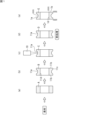
- FIGS. 5A to 5C are process diagrams illustrating a method for manufacturing a track member according to an embodiment of the present disclosure.
- FIG. 2 is a process diagram for explaining the manufacturing method employed in the examples and comparative examples.
- Patent Document 1 ⁇ Problems to be Solved by the Invention of the Present Disclosure> According to the inventions of Patent Documents 1 and 2, it is possible to extend the life of the rolling bearing member. On the other hand, the invention of Patent Document 1 aims to reduce nonmetallic inclusions throughout the entire bearing member, and is therefore expensive as a bearing material. Therefore, when the bearing material of Patent Document 1 is used, it is difficult to provide a rolling bearing member at a low price.
- Patent Document 2 By implementing the invention of Patent Document 2, it is possible to reduce the diameter of nonmetallic inclusions with a particle size of 30 ⁇ m or more to a maximum diameter of about 20 ⁇ m. However, even if the invention of Patent Document 2 is implemented, it is difficult to further refine nonmetallic inclusions with smaller particle sizes.
- a method for manufacturing a raceway member according to the present disclosure is a method for manufacturing a raceway member having a raceway along which rolling elements roll, comprising the steps of: A forging process for forging a metal material containing non-metallic inclusions having a circular equivalent diameter of 2 ⁇ m or more into a forged member; a turning step of turning the forged member to obtain a turned member having a portion that will become a raceway; a melting and solidifying step of melting at least a part of a surface layer portion up to a first depth immediately below a surface forming a rolling surface included in a portion that becomes the raceway of the turned member, and then solidifying the molten material to obtain a melted and solidified member; and and a heat treatment step of heat treating at least the entire surface forming the rolling contact surface of the melt-solidified member to obtain a heat-treated member.
- the method for manufacturing a raceway member disclosed herein it is possible to manufacture a raceway member for a rolling bearing in which non-metallic inclusions present directly below the rolling surface are refined and internally initiated flaking is less likely to occur. Furthermore, the method for manufacturing the raceway member described above is a method that produces little CO2 emissions.
- the method for manufacturing the raceway member further includes a surface processing step performed after the heat treatment step,
- the surface processing step preferably includes removing at least a portion of the surface forming the rolling surface of the heat-treated component from the surface to a second depth to obtain a surface-processed component.
- the method for manufacturing the balls of the present disclosure includes: A forging process for forging a metallic material containing non-metallic inclusions having a circular equivalent diameter of 2 ⁇ m or more into a spherical forged member; a first grinding step of grinding a surface of the forged member to obtain a first ground member; a melting and solidifying step of melting at least a part of a surface layer portion up to a third depth just below the surface of the first ground member, and then solidifying the molten material to obtain a melted and solidified member; a heat treatment step of heat treating the entire surface of the melt-solidified member to obtain a heat-treated member; and a second grinding step of grinding the surface of the heat-treated member to obtain a second ground member. Equipped with. According to the ball manufacturing method disclosed herein, non-metallic inclusions near the surface are refined, making it possible to manufacture balls for bearings that are less susceptible to internally initiated flaking. In addition, the method for manufacturing the balls produces less CO2 emissions.
- the manufacturing method of the roller according to the present disclosure includes: A forging process for forging a metal material containing non-metallic inclusions with a circle equivalent diameter of 2 ⁇ m or more into a roller-shaped forged member; a first grinding step of grinding at least a peripheral surface of the forged member to obtain a first ground member; a melting and solidifying step of melting at least a part of a surface layer portion up to a fourth depth just below the peripheral surface of the first ground member, and then solidifying the molten material to obtain a melted and solidified member;
- the method includes a heat treatment step of heat-treating at least the entire peripheral surface of the melt-solidified member to obtain a heat-treated member, and a second grinding step of grinding at least the peripheral surface of the heat-treated member to obtain a second ground member.
- non-metallic inclusions present directly below the rolling surface are refined, making it possible to manufacture rollers for bearings that are less susceptible to internally initiated flaking. Furthermore, the above-mentioned method for manufacturing the rollers produces little CO2 emissions.
- First Embodiment 1 is a process diagram for explaining a method for manufacturing a raceway member according to the present embodiment.
- a method for manufacturing an inner ring of a ball bearing will be explained as a method for manufacturing a raceway member having a raceway along which rolling elements roll.
- the method for manufacturing the inner ring comprises the steps of: (a) a forging step, (b) a turning step, (c) a melting and solidifying step, (d) a heat treatment step, and (e) a surface machining step are carried out in this order.
- Known methods used in the manufacture of inner rings can be applied to the steps other than the melting and solidifying step (c). Each step will be described below in order.
- the annular raw material A is produced by forging a metal raw material containing nonmetallic inclusions having an equivalent circle diameter of 2 ⁇ m or more.
- a metal raw material containing nonmetallic inclusions having an equivalent circle diameter of 2 ⁇ m or more.
- the above-mentioned metallic material for example, there can be mentioned a steel material whose inclusion evaluation result satisfies the parameters in Table 1 below in a measurement based on JIS G0555 (2003): Microscopic examination method for non-metallic inclusions in steel using a point counting method.
- the metallic material may be, for example, a steel material whose inclusion evaluation results satisfy the parameters in Table 2 below in a measurement according to ASTM E45 A method.
- Steel materials satisfying these parameters contain nonmetallic inclusions with a circular equivalent diameter of 2 ⁇ m or more.
- the measurement of nonmetallic inclusions by the above-mentioned methods in accordance with JIS G0555 (2003) or ASTM E45 A method can be performed using a commercially available nonmetallic inclusion measuring device (for example, METALSPECTOR II-C manufactured by Toshiba Digital Solutions Corporation).
- the above-mentioned metallic materials include carbon steels for machine construction such as S45C and S55C, high carbon chromium bearing steels such as SUJ2, and alloy steels such as SAE5120 and SC420. These steel materials usually contain non-metallic inclusions with a circular equivalent diameter of 2 ⁇ m or more.
- a raw material (steel material) contains non-metallic inclusions with an equivalent circle diameter of 2 ⁇ m or more is determined by observing a cut surface of the raw material before forging and judging whether or not the largest non-metallic inclusion in the observation area has an equivalent circle diameter of 2 ⁇ m or more.
- the above-mentioned circle equivalent diameter is also called the Heywood diameter, and refers to the diameter of a perfect circle equivalent to the area of the observed nonmetallic inclusion. In this process, spheroidizing annealing may be performed after forging.
- surface 11a forming the rolling surface 1a in this step is removed in a subsequent step, and the portion that was located directly below surface 11a forming the rolling surface 1a is exposed and becomes the rolling surface 1a.
- the portion that will become the raceway is the portion that will undergo a subsequent melting and solidifying process and a surface processing process such as a grinding process to form the raceway.
- step (c) Melting and solidifying step: In this step (c), at least a part of the portion of the annular blank B that is the turned member that becomes the raceway is melted. Specifically, at least a part of a surface layer portion up to a first depth immediately below the surface 11a that forms the rolling surface 1a included in the portion that becomes the raceway is melted. The molten annular blank B then solidifies. The annular material B is irradiated with laser light on a part of the surface of the annular material B, and a surface layer portion of a predetermined depth including the surface irradiated with the laser light is melted.
- nonmetallic inclusions that were present in the portion to be melted before melting are refined.
- nonmetallic inclusions with an equivalent circle diameter of about 30 to 60 ⁇ m can be refined to an equivalent circle diameter of about 0.1 to 1.0 ⁇ m, for example.
- the area irradiated with the laser light in step (c) is a part of the annular material B. Specifically, it is a part or all of the surface 11a that forms the rolling surface 1a of the annular material B. Preferably, it is the entire surface 11a that forms the rolling surface 1a of the annular material B.
- Non-metallic inclusions that exist directly below the rolling surface are the cause of internally initiated spalling. At least the rolling surface that has non-metallic inclusions should be irradiated with the laser light. This is because non-metallic inclusions in other parts do not contribute to the occurrence of internally initiated spalling.
- the depth of the portion to be melted may be determined taking into consideration the depth at which the maximum shear stress occurs in the completed inner ring.
- the shear stress of the inner ring increases from the rolling surface toward the depth direction, reaches a maximum value at a certain depth, and then gradually decreases toward the depth direction.
- the depth at which this shear stress reaches its maximum value is the depth at which the maximum shear stress occurs.
- the deeper of the two depths at which 90% of the maximum shear stress occurs is used as an index, and melting is performed up to a depth equal to or greater than this depth. Note that in this specification, the "depth at which 90% of the maximum shear stress occurs" refers to the deeper of the two depths at which 90% of the maximum shear stress occurs, unless otherwise specified.
- the surface 11a that forms the rolling surface 1a is removed by grinding or the like in a subsequent process.
- the depth to be melted in step (c) is determined taking into consideration the depth to be removed in the subsequent step.
- the maximum depth of the melted portion is not particularly limited as long as the melted portion does not penetrate to the inner circumference 11d of the annular raw material B.
- the depth of the portion to be melted may be determined taking into consideration the depth at which the maximum shear stress occurs in the completed inner ring, and should be equal to or greater than the total depth of the depth at which 90% of the maximum shear stress occurs and the depth to be removed in a subsequent process.
- the depth of the portion to be melted is preferably about 120 to 200% of the total depth of the depth at which 90% of the maximum shear stress occurs and the depth to be removed in a subsequent process.
- the preferred depth of the melted portion cannot be generalized as it depends on the depth at which the maximum shear stress occurs and the depth to be removed in the finishing process, but it is usually around 300 to 2000 ⁇ m.
- the laser 10 used in this step may be any laser capable of melting the nonmetallic inclusions. Specifically, it is preferable that the laser 10 be capable of heating the irradiated area of the laser beam to 2500° C. or higher. Specific examples of the laser 10 include a YAG laser, a YVO laser, a semiconductor laser, and a fiber laser.
- the steel material can be melted and solidified continuously by scanning the laser light and changing the irradiation position of the laser light over time.
- the depth of the melted portion and the cooling speed after melting can be adjusted by adjusting the output and moving speed of the laser beam. Specifically, the depth of the melted portion can be made deeper by increasing the output of the laser beam and slowing the moving speed of the laser 10. On the other hand, the cooling speed can be made faster by increasing the moving speed of the laser 10.
- the cooling rate of the molten portion is preferably 1200 to 10000° C./sec for the surface of the molten portion.
- a cooling rate is suitable for refining nonmetallic inclusions.
- the cooling rate may be calculated based on the temperature change measured using a thermometer having sufficient time resolution, such as a radiation thermometer.
- step (d) Heat treatment step: In this step (d), the intermediate material C, which has been subjected to the melting and solidifying steps and in which the non-metallic inclusions have been reduced in size, is subjected to a heat treatment to produce an intermediate material D, which is a heat-treated member.
- a heat treatment for example, quenching and tempering are performed, and carburizing treatment, carbonitriding treatment, etc. may also be performed as the heat treatment.
- the above-mentioned hardening may be through hardening, induction hardening, flame hardening, etc.
- the above-mentioned hardening may be full hardening or partial hardening.
- the above-mentioned partial hardening is performed on at least the entire surface 11a forming the rolling surface 1a formed on the intermediate material C.
- step (e) Surface processing process: In this step (e), the surface 11a forming the rolling surface 1a of the intermediate material D that has been heat treated is subjected to surface processing, and an inner ring E having a rolling surface 1a finished to a predetermined accuracy is formed. .
- the surface 11a forming the rolling surface 1a is machined, and the end face and inner circumference of the intermediate material D are also machined to produce an inner ring E having an end face 1b and inner circumference 1d finished to a predetermined precision. It is preferable to set the above.
- the surface processing that can be adopted includes, for example, grinding processing, cutting processing, and the like.
- the surface 11a forming the rolling surface 1a of the intermediate material D is removed to a predetermined depth (second depth).
- the depth to be removed is set so that the depth of the part that remains after removal, which was melted and solidified in the melting and solidifying process, is equal to or greater than the depth at which 90% of the maximum shear stress occurs.
- the inner ring of the rolling bearing can be manufactured.
- the inner ring manufactured in this embodiment has no non-metallic inclusions with a circle equivalent diameter of 30 ⁇ m or more, or even if present, only in small amounts, up to the depth where 90% of the maximum shear stress occurs directly below the rolling surface, and therefore is less susceptible to internally initiated flaking over long periods of time.
- the inner ring can be manufactured with less CO2 emissions.
- the present embodiment relates to a method for manufacturing balls as rolling bearing members.
- the method for manufacturing the ball according to this embodiment is as follows: (a) a forging step, (b) a first grinding step, (c) a melting and solidifying step, (d) a heat treatment step, and (e) a second grinding step are carried out in this order.
- known methods used in the manufacture of balls for rolling bearings can be applied to the steps other than the melting and solidifying step (c). Each step will be described below in the order of steps, focusing on the differences from the first embodiment.
- the spherical intermediate material F is produced by forging a metallic material containing non-metallic inclusions having a circle equivalent diameter of 2 ⁇ m or more.
- the metallic material may be the same as that used in the first embodiment.
- spheroidizing annealing may be performed after forging.
- step (c) Melting and solidifying step: In this step (c), at least a part of a surface layer portion up to a third depth just below the surface of the ground intermediate material G is melted. Thereafter, the melted material is solidified.
- the intermediate material G becomes a spherical intermediate material H in which non-metallic inclusions immediately below the surface are refined.
- the intermediate material G may be melted in the same manner as in the first embodiment.
- solidification of the melted portion may be performed in the same manner as in the first embodiment.
- the depth of the portion to be melted (third depth) can be determined taking into consideration the depth at which the maximum shear stress occurs in the finished ball, and should be greater than or equal to the sum of the depth at which 90% of the maximum shear stress occurs and the depth to which it is removed in a subsequent process.
- the depth of the portion to be melted is preferably about 120 to 200% of the total depth of the depth at which 90% of the maximum shear stress occurs and the depth to be removed in a subsequent step.
- a preferred value for the depth of the melted portion cannot be generally stated, but is usually about 300 to 2000 ⁇ m.
- step (d) Heat treatment step: In this step (d), the intermediate material H, in which the non-metallic inclusions have been refined through the melting and solidifying steps, is subjected to a heat treatment to produce a spherical intermediate material I, which is a heat-treated component.
- a heat treatment to produce a spherical intermediate material I, which is a heat-treated component.
- the heat treatment may be of the same type and method as the heat treatment in the first embodiment.
- Second grinding step In this process (e), the intermediate material I which has completed the heat treatment has its surface ground to become balls J having rolling surfaces finished to a predetermined precision.
- this step (e) the surface of the intermediate material I is removed to a predetermined depth (fifth depth) from the surface.
- the depth to be removed is set so that the depth from the surface of the part that remains after the removal and that has been melted and solidified in the melting and solidifying step is equal to or greater than the depth at which 90% of the maximum shear stress occurs.
- balls for a rolling bearing are manufactured.
- the balls manufactured in this embodiment have no non-metallic inclusions with a circle equivalent diameter of 30 ⁇ m or more from the surface to the depth where 90% of the maximum shear stress occurs, or even if they are present, they are in small amounts, so that internally initiated spalling is less likely to occur over a long period of time. Furthermore, according to this embodiment, balls can be manufactured with less CO2 emissions.
- the present embodiment relates to a method for manufacturing a roller as a rolling bearing member.
- the method for manufacturing a roller according to this embodiment is as follows: (a) a forging step, (b) a first grinding step, (c) a melting and solidifying step, (d) a heat treatment step, and (e) a second grinding step are carried out in this order.
- known methods used in the manufacture of rollers for rolling bearings can be applied to the steps other than the melting and solidifying step (c). Each step will be described below in the order of steps, focusing on the differences from the first and second embodiments.
- a roller-shaped intermediate material K is produced by forging a metal material containing non-metallic inclusions having a circle equivalent diameter of 2 ⁇ m or more.
- the metallic material may be the same as that used in the first embodiment.
- spheroidizing annealing may be performed after forging.
- step (b) First grinding step: In this step (b), at least the peripheral surface of the intermediate material K, which is a forged member, is ground to produce a roller-shaped intermediate material L. When the intermediate material L is produced, it is preferable to also grind the end surfaces of the intermediate material K. Although burrs and the like are present on the peripheral surface of the intermediate material K produced in the forging process (a) above, by carrying out this process (B), the burrs and the like are removed, and an intermediate material L having a relatively smooth peripheral surface is produced.
- step (c) Melting and solidifying step: In this step (c), at least a part of a surface layer portion up to a fourth depth immediately below the peripheral surface of the ground intermediate material L is melted. Thereafter, the melted material is solidified.
- the intermediate material L becomes an intermediate material M having a roller shape in which non-metallic inclusions immediately below the peripheral surface are refined.
- the intermediate material L may be melted in the same manner as in the first embodiment.
- solidification of the melted portion may be performed in the same manner as in the first embodiment.
- the depth of the portion to be melted (fourth depth) can be determined taking into consideration the depth at which the maximum shear stress occurs in the completed product, and can be set to a depth greater than or equal to the sum of the depth at which 90% of the maximum shear stress occurs and the depth to which it is removed in a subsequent process.
- the depth of the portion to be melted is preferably about 120 to 200% of the total depth of the depth at which 90% of the maximum shear stress occurs and the depth to be removed in a subsequent step.
- a preferred value for the depth of the melted portion cannot be generally stated, but is usually about 300 to 2000 ⁇ m.
- step (d) Heat treatment step: In this step (d), the intermediate material M in which the non-metallic inclusions have been refined through the melting and solidifying steps is subjected to a heat treatment, and a roller-shaped intermediate material N, which is a heat-treated member, is produced. Here, at least the entire peripheral surface of the intermediate material M is heat-treated.
- the heat treatment may be of the same type and method as the heat treatment in the first embodiment.
- step (e) Second grinding step: In this step (e), the intermediate material N after the heat treatment is ground at its circumferential surface to become a roller O having a rolling surface finished to a predetermined precision. When the circumferential surface of the intermediate material N is ground, the end surface of the intermediate material N may also be ground.
- the peripheral surface of the intermediate material N is removed from the surface to a predetermined depth (sixth depth). At this time, the depth to be removed is set so that the depth from the surface of the part that has been melted and solidified in the melting and solidifying step and remains after the removal is equal to or greater than the depth at which 90% of the maximum shear stress occurs.
- rollers of the rolling bearing are manufactured.
- rollers manufactured in this embodiment there are no non-metallic inclusions with a circle equivalent diameter of 30 ⁇ m or more, or even if present, they are in small amounts, from the circumferential surface to the depth where 90% of the maximum shear stress is generated, and therefore internally initiated spalling is less likely to occur over a long period of time.
- rollers can be manufactured with small amounts of CO2 emissions.
- the products produced by the manufacturing method according to the embodiment of the present disclosure are not limited to inner rings, balls, and rollers, which are components of rolling bearings.
- a raceway member having a raceway along which rolling elements roll such as an outer ring of a rolling bearing.
- FIG. 2 is a diagram for explaining the manufacturing process employed in the examples and comparative examples. As shown in FIG. 2, in Examples 1 and 2, the melting and solidifying step was carried out, whereas in Comparative Example 1, the melting and solidifying step was not carried out.
- the heat treatment consisted of a quenching treatment in which the material was heated at 830° C. for 35 minutes, followed by oil cooling, and a tempering treatment in which the material was heated at 180° C. for 120 minutes.
- Example 1 Five disk-shaped materials were produced in the same manner as in step (1) of Comparative Example 1. (2) The disk-shaped material was subjected to a melting and solidifying process in which a part of one side of the disk-shaped material was irradiated with laser light. In the melting and solidifying process, a fiber laser was used, and the disk-shaped material was irradiated with laser light under the conditions of laser A shown in Table 3. The laser beam was irradiated so as to draw a circle having a diameter of about 38.5 mm. The disk-shaped material was melted by the laser beam over a region of 300 ⁇ m from the surface, and then solidified.
- Example 2 Evaluation disks (five disks) of Example 2 were completed in the same manner as Example 1, except that a part of one side of the disk-shaped material was irradiated with the laser light under the conditions of laser B shown in Table 3. The disk-shaped material was melted by the laser light over 300 ⁇ m from the surface, and then solidified.
- Example 1 and Example 2 In the evaluation disks of Example 1 and Example 2, no nonmetallic inclusions with an equivalent circle diameter of 30 ⁇ m or more were found on one side of the disk-shaped raw material. On the other hand, in the evaluation disk of the Comparative Example, nonmetallic inclusions with an equivalent circle diameter of 30 ⁇ m or more were found on one side of the disk-shaped raw material. The number of nonmetallic inclusions with an equivalent circle diameter of 30 ⁇ m or more is shown in Table 4.
- Rolling surface 1b End face 1d: Inner circumference 10: Laser 11a: Surface forming the rolling surface A, B, C, D: Intermediate material E: Inner ring
Landscapes
- Engineering & Computer Science (AREA)
- General Engineering & Computer Science (AREA)
- Mechanical Engineering (AREA)
- Manufacturing & Machinery (AREA)
- Rolling Contact Bearings (AREA)
Abstract
転動体が転走する軌道を有する軌道部材の製造方法であって、円相当径2μm以上の非金属介在物を含む金属製の素材を鍛造して鍛造済み部材とする鍛造工程、前記鍛造済み部材を旋削して軌道となる部分を有する旋削済み部材とする旋削工程、前記旋削済み部材が有する前記軌道となる部分に含まれる転走面を形成する面から第1深さまでの表層部分の少なくとも一部を融解し、その後、融解した素材を凝固させて融解凝固済み部材とする融解凝固工程、及び、前記融解凝固済み部材の表面のうち、少なくとも転走面を形成する面の全てを熱処理して熱処理済み部材とする熱処理工程、を備える。
Description
本開示は、軌道部材の製造方法、玉の製造方法、及び、ころの製造方法に関する。
転がり軸受などに用いられる軸受材料は、転動疲労寿命を長くすることを要求される。軸受の転動疲労寿命は、材料中に存在する非金属介在物に影響される。また、非金属介在物の寸法が大きいほど、軸受の転動疲労寿命に繋がる内部起点剥離が発生しやすい。
特許文献1は、非金属介在物形成元素であるS及びOを、それぞれS:0.025質量%以下、O:0.0012質量%以下とした特定の組成を有する軸受材料を提案している。
特許文献2は、非金属介在物を原因とする内部起点剥離の発生を抑制し、転がり軸受部材の長寿命化を図るべく、低清浄度鋼を材料とする転がり軸受部材であって、当該転がり軸受部材の転動面の表層部に存在する非金属介在物が、粉砕されて小径化されている転がり軸受部材を提案している。
本開示の一態様に係る軌道部材の製造方法は、転動体が転走する軌道を有する軌道部材の製造方法であって、
円相当径2μm以上の非金属介在物を含む金属製の素材を鍛造して鍛造済み部材とする鍛造工程、
上記鍛造済み部材を旋削して軌道となる部分を有する旋削済み部材とする旋削工程、
上記旋削済み部材が有する上記軌道となる部分に含まれる転走面を形成する面の直下の、第1深さまでの表層部分の少なくとも一部を融解し、その後、融解した素材を凝固させて融解凝固済み部材とする融解凝固工程、及び、
上記融解凝固済み部材の表面のうち、少なくとも転走面を形成する面の全てを熱処理して熱処理済み部材とする熱処理工程、を備える。
円相当径2μm以上の非金属介在物を含む金属製の素材を鍛造して鍛造済み部材とする鍛造工程、
上記鍛造済み部材を旋削して軌道となる部分を有する旋削済み部材とする旋削工程、
上記旋削済み部材が有する上記軌道となる部分に含まれる転走面を形成する面の直下の、第1深さまでの表層部分の少なくとも一部を融解し、その後、融解した素材を凝固させて融解凝固済み部材とする融解凝固工程、及び、
上記融解凝固済み部材の表面のうち、少なくとも転走面を形成する面の全てを熱処理して熱処理済み部材とする熱処理工程、を備える。
本開示の一態様に係る玉の製造方法は、
円相当径2μm以上の非金属介在物を含む金属製の素材を鍛造して球状の鍛造済み部材とする鍛造工程、
上記鍛造済み部材の表面を研削して第1の研削済み部材とする第1研削工程、
上記第1の研削済み部材の表面の直下の、第3深さまでの表層部分の少なくとも一部を融解し、その後、融解した素材を凝固させて融解凝固済み部材とする融解凝固工程、
上記融解凝固済み部材の表面全体を熱処理して熱処理済み部材とする熱処理工程、及び
熱処理済み部材の表面を研削して第2の研削済み部材とする第2研削工程、を備える。
円相当径2μm以上の非金属介在物を含む金属製の素材を鍛造して球状の鍛造済み部材とする鍛造工程、
上記鍛造済み部材の表面を研削して第1の研削済み部材とする第1研削工程、
上記第1の研削済み部材の表面の直下の、第3深さまでの表層部分の少なくとも一部を融解し、その後、融解した素材を凝固させて融解凝固済み部材とする融解凝固工程、
上記融解凝固済み部材の表面全体を熱処理して熱処理済み部材とする熱処理工程、及び
熱処理済み部材の表面を研削して第2の研削済み部材とする第2研削工程、を備える。
本開示の一態様に係るころの製造方法は、
円相当径2μm以上の非金属介在物を含む金属製の素材を鍛造してころ形状の鍛造済み部材とする鍛造工程、
上記鍛造済み部材の少なくとも周面を研削して第1の研削済み部材とする第1研削工程、
上記第1の研削済み部材の周面の直下の、第4深さまでの表層部分の少なくとも一部を融解し、その後、融解した素材を凝固させて融解凝固済み部材とする融解凝固工程、
上記融解凝固済み部材の少なくとも周面全体を熱処理して熱処理済み部材とする熱処理工程、及び
熱処理済み部材の少なくとも周面を研削して第2の研削済み部材とする第2研削工程、を備える。
円相当径2μm以上の非金属介在物を含む金属製の素材を鍛造してころ形状の鍛造済み部材とする鍛造工程、
上記鍛造済み部材の少なくとも周面を研削して第1の研削済み部材とする第1研削工程、
上記第1の研削済み部材の周面の直下の、第4深さまでの表層部分の少なくとも一部を融解し、その後、融解した素材を凝固させて融解凝固済み部材とする融解凝固工程、
上記融解凝固済み部材の少なくとも周面全体を熱処理して熱処理済み部材とする熱処理工程、及び
熱処理済み部材の少なくとも周面を研削して第2の研削済み部材とする第2研削工程、を備える。
<本開示の発明が解決しようとする課題>
特許文献1及び2の発明によれば、転がり軸受部材の長寿命化を図ることができる。
一方、特許文献1の発明は、軸受部材全体で非金属介在物の減少を図っているため、軸受材料としては高価である。そのため、特許文献1の軸受材料を使用した場合に、転がり軸受部材を安価に提供することは困難であった。
特許文献1及び2の発明によれば、転がり軸受部材の長寿命化を図ることができる。
一方、特許文献1の発明は、軸受部材全体で非金属介在物の減少を図っているため、軸受材料としては高価である。そのため、特許文献1の軸受材料を使用した場合に、転がり軸受部材を安価に提供することは困難であった。
特許文献2の発明を実施すると、粒径が30μm以上の非金属介在物を最大径20μm程度に小径化することは可能である。しかしながら、特許文献2の発明を実施しても、粒径がより小さい非金属介在物を更に微細化することは困難であった。
<本開示の発明の効果>
本開示の発明によれば、内部起点剥離の発生しにくい軌道部材、玉、及びころを製造することができる。
本開示の発明によれば、内部起点剥離の発生しにくい軌道部材、玉、及びころを製造することができる。
<本開示の発明の実施形態の概要>
このような状況のもと、本発明者らは、内部起点剥離の発生しにくい転がり軸受部材を製造する新たな方法を見出し、本開示の発明を完成した。
以下、本開示の発明の実施形態の概要を列記して説明する。
このような状況のもと、本発明者らは、内部起点剥離の発生しにくい転がり軸受部材を製造する新たな方法を見出し、本開示の発明を完成した。
以下、本開示の発明の実施形態の概要を列記して説明する。
(1)本開示の軌道部材の製造方法は、転動体が転走する軌道を有する軌道部材の製造方法であって、
円相当径2μm以上の非金属介在物を含む金属製の素材を鍛造して鍛造済み部材とする鍛造工程、
上記鍛造済み部材を旋削して軌道となる部分を有する旋削済み部材とする旋削工程、
上記旋削済み部材が有する上記軌道となる部分に含まれる転走面を形成する面の直下の、第1深さまでの表層部分の少なくとも一部を融解し、その後、融解した素材を凝固させて融解凝固済み部材とする融解凝固工程、及び、
上記融解凝固済み部材の表面のうち、少なくとも転走面を形成する面の全てを熱処理して熱処理済み部材とする熱処理工程、を備える。
円相当径2μm以上の非金属介在物を含む金属製の素材を鍛造して鍛造済み部材とする鍛造工程、
上記鍛造済み部材を旋削して軌道となる部分を有する旋削済み部材とする旋削工程、
上記旋削済み部材が有する上記軌道となる部分に含まれる転走面を形成する面の直下の、第1深さまでの表層部分の少なくとも一部を融解し、その後、融解した素材を凝固させて融解凝固済み部材とする融解凝固工程、及び、
上記融解凝固済み部材の表面のうち、少なくとも転走面を形成する面の全てを熱処理して熱処理済み部材とする熱処理工程、を備える。
本開示の軌道部材の製造方法によれば、転走面の直下に存在する非金属介在物が微細化されており、内部起点剥離の発生しにくい転がり軸受用の軌道部材を製造することができる。
また、上記軌道部材の製造方法は、CO2排出量の少ない方法である。
また、上記軌道部材の製造方法は、CO2排出量の少ない方法である。
(2)上記軌道部材の製造方法は、上記熱処理工程の後に行う表面加工工程を更に備え、
上記表面加工工程は、上記熱処理済み部材が有する転走面を形成する面の少なくとも一部を表面から第2深さまで除去して表面加工済み部材とする、ことが好ましい。
(3)上記表面加工工程では、研削加工及び/又は切削工程を行うことが好ましい。
上記表面加工工程は、上記熱処理済み部材が有する転走面を形成する面の少なくとも一部を表面から第2深さまで除去して表面加工済み部材とする、ことが好ましい。
(3)上記表面加工工程では、研削加工及び/又は切削工程を行うことが好ましい。
(4)本開示の玉の製造方法は、
円相当径2μm以上の非金属介在物を含む金属製の素材を鍛造して球状の鍛造済み部材とする鍛造工程、
上記鍛造済み部材の表面を研削して第1の研削済み部材とする第1研削工程、
上記第1の研削済み部材の表面の直下の、第3深さまでの表層部分の少なくとも一部を融解し、その後、融解した素材を凝固させて融解凝固済み部材とする融解凝固工程、
上記融解凝固済み部材の表面全体を熱処理して熱処理済み部材とする熱処理工程、及び
熱処理済み部材の表面を研削して第2の研削済み部材とする第2研削工程、
を備える。
本開示の玉の製造方法によれば、表面近くに存在する非金属介在物が微細化されており、内部起点剥離の発生しにくい軸受用の玉を製造することができる。
また、上記玉の製造方法は、CO2排出量の少ない方法である。
円相当径2μm以上の非金属介在物を含む金属製の素材を鍛造して球状の鍛造済み部材とする鍛造工程、
上記鍛造済み部材の表面を研削して第1の研削済み部材とする第1研削工程、
上記第1の研削済み部材の表面の直下の、第3深さまでの表層部分の少なくとも一部を融解し、その後、融解した素材を凝固させて融解凝固済み部材とする融解凝固工程、
上記融解凝固済み部材の表面全体を熱処理して熱処理済み部材とする熱処理工程、及び
熱処理済み部材の表面を研削して第2の研削済み部材とする第2研削工程、
を備える。
本開示の玉の製造方法によれば、表面近くに存在する非金属介在物が微細化されており、内部起点剥離の発生しにくい軸受用の玉を製造することができる。
また、上記玉の製造方法は、CO2排出量の少ない方法である。
(5)本開示のころの製造方法は、
円相当径2μm以上の非金属介在物を含む金属製の素材を鍛造してころ形状の鍛造済み部材とする鍛造工程、
上記鍛造済み部材の少なくとも周面を研削して第1の研削済み部材とする第1研削工程、
上記第1の研削済み部材の周面の直下の、第4深さまでの表層部分の少なくとも一部を融解し、その後、融解した素材を凝固させて融解凝固済み部材とする融解凝固工程、
上記融解凝固済み部材の少なくとも周面全体を熱処理して熱処理済み部材とする熱処理工程、及び
熱処理済み部材の少なくとも周面を研削して第2の研削済み部材とする第2研削工程、を備える。
本開示のころ製造方法によれば、転動面(ころの周面)の直下に存在する非金属介在物が微細化されており、内部起点剥離の発生しにくい軸受用のころを製造することができる。
また、上記ころの製造方法は、CO2排出量の少ない方法である。
円相当径2μm以上の非金属介在物を含む金属製の素材を鍛造してころ形状の鍛造済み部材とする鍛造工程、
上記鍛造済み部材の少なくとも周面を研削して第1の研削済み部材とする第1研削工程、
上記第1の研削済み部材の周面の直下の、第4深さまでの表層部分の少なくとも一部を融解し、その後、融解した素材を凝固させて融解凝固済み部材とする融解凝固工程、
上記融解凝固済み部材の少なくとも周面全体を熱処理して熱処理済み部材とする熱処理工程、及び
熱処理済み部材の少なくとも周面を研削して第2の研削済み部材とする第2研削工程、を備える。
本開示のころ製造方法によれば、転動面(ころの周面)の直下に存在する非金属介在物が微細化されており、内部起点剥離の発生しにくい軸受用のころを製造することができる。
また、上記ころの製造方法は、CO2排出量の少ない方法である。
<本開示の発明の実施形態の詳細>
以下、本開示の発明の実施形態について説明する。
(第1実施形態)
図1は、本実施形態に係る軌道部材の製造方法を説明するための工程図である。図1によって、転動体が転走する軌道を有する軌道部材の製造方法として、玉軸受の内輪の製造方法を説明する。
上記内輪の製造方法は、
(a)鍛造工程、(b)旋削工程、(c)融解凝固工程、(d)熱処理工程、及び(e)表面加工工程、をこの順序で行う。上記(c)融解凝固工程以外は、内輪の製造で用いる公知の手法を適用することができる。
以下、工程順に各工程を説明する。
以下、本開示の発明の実施形態について説明する。
(第1実施形態)
図1は、本実施形態に係る軌道部材の製造方法を説明するための工程図である。図1によって、転動体が転走する軌道を有する軌道部材の製造方法として、玉軸受の内輪の製造方法を説明する。
上記内輪の製造方法は、
(a)鍛造工程、(b)旋削工程、(c)融解凝固工程、(d)熱処理工程、及び(e)表面加工工程、をこの順序で行う。上記(c)融解凝固工程以外は、内輪の製造で用いる公知の手法を適用することができる。
以下、工程順に各工程を説明する。
(a)鍛造工程:
本工程(a)において、環状素材Aは、円相当径2μm以上の非金属介在物を含む金属製の素材を鍛造することによって、作製される。
上記金属製の素材として、例えば、JIS G0555(2003):鋼の非金属介在物の点算法による顕微鏡試験方法、に準拠した測定において、介在物の評価結果が下記表1のパラメータを充足する鋼材が挙げられる。
本工程(a)において、環状素材Aは、円相当径2μm以上の非金属介在物を含む金属製の素材を鍛造することによって、作製される。
上記金属製の素材として、例えば、JIS G0555(2003):鋼の非金属介在物の点算法による顕微鏡試験方法、に準拠した測定において、介在物の評価結果が下記表1のパラメータを充足する鋼材が挙げられる。
上記金属製の素材として、例えば、ASTM E45 A法、に準拠した測定において、介在物の評価結果が下記表2のパラメータを充足する鋼材も挙げられる。
これらのパラメータを充足する鋼材は、円相当径2μm以上の非金属介在物を含有している。
上述したJIS G0555(2003)やASTM E45 A法、に準拠した方法による非金属介在物の測定は、市販の非金属介在物測定装置(例えば、東芝デジタルソリューション社製、METALSPECTOR II-C等)を使用して行うことができる。
上述したJIS G0555(2003)やASTM E45 A法、に準拠した方法による非金属介在物の測定は、市販の非金属介在物測定装置(例えば、東芝デジタルソリューション社製、METALSPECTOR II-C等)を使用して行うことができる。
上記金属製の素材として、S45C、S55C等の機械構造用炭素鋼、SUJ2等の高炭素クロム軸受鋼、SAE5120、SC420等の合金鋼等が挙げられる。これらの鋼材は、通常、円相当径2μm以上の非金属介在物を含有している。
本開示の実施形態において、素材(鋼材)が円相当径2μm以上の非金属介在物を含有しているか否かは、鍛造前の素材の切断面を観察し、観察領域内の最も大きい非金属介在物の円相当径が2μm以上であるか否かで判断する。
上記円相当径とは、ヘイウッド径ともいい、観察された非金属介在物の面積に相当する、真円の直径のことをいう。
本工程において、鍛造後、球状化焼鈍が行われてもよい。
上記円相当径とは、ヘイウッド径ともいい、観察された非金属介在物の面積に相当する、真円の直径のことをいう。
本工程において、鍛造後、球状化焼鈍が行われてもよい。
(b)旋削工程:
本工程(b)において、鍛造済み部材である環状素材Aの外周に旋削加工を施して、転走面1aを形成する面11aを含む軌道となる部分を有する環状素材Bが作製される。
環状素材Bは、環状素材Aの端面11b、外周11c、内周11d等も必要に応じて研削加工等で所定形状に加工され作成される。
ここで、転走面1aを形成する面11aは、後の融解凝固工程や、研削工程等の表面加工工程を経て転走面1aが形成されることになる部分である。通常、本工程における転走面1aを形成する面11aは、後工程で除去され、転走面1aを形成する面11aの直下に位置していた部分が露出して転走面1aとなる。
また、軌道となる部分は、後の融解凝固工程や、研削工程等の表面加工工程を経て軌道が形成されることになる部分である。
本工程(b)において、鍛造済み部材である環状素材Aの外周に旋削加工を施して、転走面1aを形成する面11aを含む軌道となる部分を有する環状素材Bが作製される。
環状素材Bは、環状素材Aの端面11b、外周11c、内周11d等も必要に応じて研削加工等で所定形状に加工され作成される。
ここで、転走面1aを形成する面11aは、後の融解凝固工程や、研削工程等の表面加工工程を経て転走面1aが形成されることになる部分である。通常、本工程における転走面1aを形成する面11aは、後工程で除去され、転走面1aを形成する面11aの直下に位置していた部分が露出して転走面1aとなる。
また、軌道となる部分は、後の融解凝固工程や、研削工程等の表面加工工程を経て軌道が形成されることになる部分である。
(c)融解凝固工程:
本工程(c)において、旋削済み部材である環状素材Bが有する上記軌道となる部分の少なくとも一部が融解される。具体的には、上記軌道となる部分に含まれる転走面1aを形成する面11aの直下の、第1深さまでの表層部分の少なくとも一部が融解される。その後、融解した環状素材Bは凝固する。
環状素材Bは、環状素材Bの表面の一部にレーザ光が照射されて、レーザ光が照射された表面を含む所定の深さの表層部分が融解される。レーザ光により融解された部分は、レーザ光の照射を停止すること、もしくはレーザ光の照射点が移動されることで冷却されて凝固する。
本工程(c)において、融解前に融解される部分に存在していた非金属介在物が微細化される。
非金属介在物の種類や、融解凝固条件にもよるため一概には言えないが、円相当径30~60μm程度の非金属介在物は、例えば、円相当径0.1~1.0μm程度に微細化することできる。
本工程(c)において、旋削済み部材である環状素材Bが有する上記軌道となる部分の少なくとも一部が融解される。具体的には、上記軌道となる部分に含まれる転走面1aを形成する面11aの直下の、第1深さまでの表層部分の少なくとも一部が融解される。その後、融解した環状素材Bは凝固する。
環状素材Bは、環状素材Bの表面の一部にレーザ光が照射されて、レーザ光が照射された表面を含む所定の深さの表層部分が融解される。レーザ光により融解された部分は、レーザ光の照射を停止すること、もしくはレーザ光の照射点が移動されることで冷却されて凝固する。
本工程(c)において、融解前に融解される部分に存在していた非金属介在物が微細化される。
非金属介在物の種類や、融解凝固条件にもよるため一概には言えないが、円相当径30~60μm程度の非金属介在物は、例えば、円相当径0.1~1.0μm程度に微細化することできる。
本工程(c)でレーザ光が照射される領域は、環状素材Bの一部である。具体的にいうと、環状素材Bが有する転走面1aを形成する面11aの一部又は全部である。好ましくは、環状素材Bが有する転走面1aを形成する面11aの全部である。転走面の直下に存在する非金属介在物は内部起点剥離の原因となる。少なくとも非金属介在物のある転走面にレーザ光が照射されるべきである。その他の部分の非金属介在物は、内部起点剥離の発生に寄与しないからである。
本工程(c)において、融解させる部分の深さは、完成した内輪における最大せん断応力が発生する深さを考慮して決定すればよい。
内輪のせん断応力は、転走面から深さ方向に向かって上々に大きくなり、ある深さで最大値を示し、そこからは深さ方向に向かって徐々に小さくなる。このせん断応力の最大値を示す深さのことが、最大せん断応力が発生する深さである。
本工程では、2ヵ所ある最大せん断応力の90%の応力が発生する深さのうちの深い方の深さを指標とし、この深さ以上の深さの部分まで融解させる。なお、本明細書において「最大せん断応力の90%の応力が発生する深さ」と記載した場合、特に断りのない限り、2ヵ所ある最大せん断応力の90%の応力が発生する深さのうちの深い方の深さ、を指す。
内輪のせん断応力は、転走面から深さ方向に向かって上々に大きくなり、ある深さで最大値を示し、そこからは深さ方向に向かって徐々に小さくなる。このせん断応力の最大値を示す深さのことが、最大せん断応力が発生する深さである。
本工程では、2ヵ所ある最大せん断応力の90%の応力が発生する深さのうちの深い方の深さを指標とし、この深さ以上の深さの部分まで融解させる。なお、本明細書において「最大せん断応力の90%の応力が発生する深さ」と記載した場合、特に断りのない限り、2ヵ所ある最大せん断応力の90%の応力が発生する深さのうちの深い方の深さ、を指す。
本実施形態において、転走面1aを形成する面11aは、後工程において研削等されて除去される。
このように、本工程(c)でレーザ光を照射する面が、後工程で除去される場合は、後工程で除去される深さも考慮して、本工程(c)で融解する深さを決定する。
一方、上記融解させる部分の深さの最大値は、融解部分を環状素材Bの内周11dまで貫通させないような深さであれば特に限定されない。
上記融解させる部分の深さは、完成した内輪における最大せん断応力が発生する深さを考慮して決定すればよく、最大せん断応力の90%の応力が発生する深さと、後工程で除去される深さとの合計深さ以上の深さとするのがよい。
上記融解させる部分の深さは、最大せん断応力の90%の応力が発生する深さと、後工程で除去される深さとの合計深さの120~200%程度の深さとすることが好ましい。
このように、本工程(c)でレーザ光を照射する面が、後工程で除去される場合は、後工程で除去される深さも考慮して、本工程(c)で融解する深さを決定する。
一方、上記融解させる部分の深さの最大値は、融解部分を環状素材Bの内周11dまで貫通させないような深さであれば特に限定されない。
上記融解させる部分の深さは、完成した内輪における最大せん断応力が発生する深さを考慮して決定すればよく、最大せん断応力の90%の応力が発生する深さと、後工程で除去される深さとの合計深さ以上の深さとするのがよい。
上記融解させる部分の深さは、最大せん断応力の90%の応力が発生する深さと、後工程で除去される深さとの合計深さの120~200%程度の深さとすることが好ましい。
上記融解させる部分の深さの好ましい数値は、最大せん断応力が発生する深さや、仕上げ工程で除去する深さにもよるため一概にはいえないが、通常、300~2000μm程度である。
本工程で使用するレーザ10は、非金属介在物を融解させることができるものであればよい。具体的にいうと、レーザ光の照射領域を2500℃以上に加熱することができるものが好ましい。
レーザ10の具体例として、例えば、YAGレーザ、YVOレーザ、半導体レーザ、ファイバーレーザ等が挙げられる。
レーザ10の具体例として、例えば、YAGレーザ、YVOレーザ、半導体レーザ、ファイバーレーザ等が挙げられる。
本工程において、レーザ光を走査し、レーザ光の照射位置を経時的に変化させることにより、鋼材の融解と凝固とを連続的に行うことができる。
また、レーザ光の出力及び移動速度を調整することによって、融解させる部分の深さや融解後の冷却速度を調整することができる。具体的にいうと、レーザ光の出力を大きくしたり、レーザ10の移動速度を遅くしたりすることにより融解させる部分の深さを深くすることができる。一方、レーザ10の移動速度を速くすることにより冷却速度を速くすることができる。
また、レーザ光の出力及び移動速度を調整することによって、融解させる部分の深さや融解後の冷却速度を調整することができる。具体的にいうと、レーザ光の出力を大きくしたり、レーザ10の移動速度を遅くしたりすることにより融解させる部分の深さを深くすることができる。一方、レーザ10の移動速度を速くすることにより冷却速度を速くすることができる。
本工程において、融解部分の冷却速度は、当該融解部分の表面の冷却速度が1200~10000℃/secであることが好ましい。
このような冷却速度が、非金属介在物の微細化に適している。
上記冷却速度は、放射温度計等の十分な時間分解能を有する温度計を用いて測定した温度変化に基づいて算出すればよい。
このような冷却速度が、非金属介在物の微細化に適している。
上記冷却速度は、放射温度計等の十分な時間分解能を有する温度計を用いて測定した温度変化に基づいて算出すればよい。
本工程を終えた後、転走面1aを形成する面11aの直下における、最大せん断応力の90%の応力が発生する深さと後工程で除去する深さの合計深さまでの部分のうち、本工程で融解された部分に、円相当径30μm以上の非金属介在物は、存在しない。
この場合、長期間に亘って内部起点剥離は、抑制される。
この場合、長期間に亘って内部起点剥離は、抑制される。
(d)熱処理工程:
本工程(d)において、上記融解凝固工程を経て、非金属介在物が微細化された中間素材Cは、熱処理が施されて、熱処理済み部材である中間素材Dが作製される。
上記熱処理として、例えば、焼入れ及び焼戻しが行われる。また、上記熱処理として、浸炭処理や浸炭窒化処理等が行われてもよい。
上記焼入れとして、ズブ焼入れ、高周波焼入れ、炎焼焼入れ等が挙げられる。また、上記焼入れは、全体焼入れであってもよいし、部分焼入れであってもよい。上記部分焼入れは、少なくとも中間素材Cに形成された転走面1aを形成する面11aの全体に対して行われる。
本工程(d)において、上記融解凝固工程を経て、非金属介在物が微細化された中間素材Cは、熱処理が施されて、熱処理済み部材である中間素材Dが作製される。
上記熱処理として、例えば、焼入れ及び焼戻しが行われる。また、上記熱処理として、浸炭処理や浸炭窒化処理等が行われてもよい。
上記焼入れとして、ズブ焼入れ、高周波焼入れ、炎焼焼入れ等が挙げられる。また、上記焼入れは、全体焼入れであってもよいし、部分焼入れであってもよい。上記部分焼入れは、少なくとも中間素材Cに形成された転走面1aを形成する面11aの全体に対して行われる。
(e)表面加工工程:
本工程(e)において、熱処理が完了した中間素材Dの転走面1aを形成する面11aは、表面加工を施され、所定の精度に仕上げた転走面1aを有する内輪Eが形成される。
また、本工程において、転走面1aを形成する面11aが、加工されるとともに、中間素材Dの端面及び内周も加工し、所定精度に仕上げられた端面1b及び内周1dを有する内輪Eとすることが好ましい。
本工程(e)において、表面加工は、例えば、研削加工、切削加工等が採用できる。
本工程(e)において、熱処理が完了した中間素材Dの転走面1aを形成する面11aは、表面加工を施され、所定の精度に仕上げた転走面1aを有する内輪Eが形成される。
また、本工程において、転走面1aを形成する面11aが、加工されるとともに、中間素材Dの端面及び内周も加工し、所定精度に仕上げられた端面1b及び内周1dを有する内輪Eとすることが好ましい。
本工程(e)において、表面加工は、例えば、研削加工、切削加工等が採用できる。
本工程(e)において、中間素材Dの転走面1aを形成する面11aは、所定の深さ(第2深さ)で除去される。このとき、除去する深さは、除去後に残っている上記融解凝固工程で融解、凝固した部分の深さが、最大せん断応力の90%の応力が生じる深さ以上の深さとなるように設定する。
このような工程(a)~(e)を行うことにより、転がり軸受の内輪を製造することができる。
本実施形態で製造された内輪は、転走面の直下の最大せん断応力の90%の応力が発生する深さまでに、粒径が円相当径で30μm以上の非金属介在物が存在しないか、又は存在しても少量であるため、長期間に亘って内部起点剥離が発生しにくい。
また、本実施形態によると、少ないCO2排出量で内輪を製造することができる。
本実施形態で製造された内輪は、転走面の直下の最大せん断応力の90%の応力が発生する深さまでに、粒径が円相当径で30μm以上の非金属介在物が存在しないか、又は存在しても少量であるため、長期間に亘って内部起点剥離が発生しにくい。
また、本実施形態によると、少ないCO2排出量で内輪を製造することができる。
(第2実施形態)
本実施形態は、転がり軸受部材としての玉の製造方法に関する。
本実施形態に係る玉の製造方法は、
(a)鍛造工程、(b)第1研削工程、(c)融解凝固工程、(d)熱処理工程、及び(e)第2研削工程、をこの順序で行う。このとき、上記(c)融解凝固工程以外は、転がり軸受用の玉の製造で用いる公知の手法を適用することができる。
以下、工程順に各工程を説明する。ここでは、第1実施形態と異なる点を中心に各工程を説明する。
本実施形態は、転がり軸受部材としての玉の製造方法に関する。
本実施形態に係る玉の製造方法は、
(a)鍛造工程、(b)第1研削工程、(c)融解凝固工程、(d)熱処理工程、及び(e)第2研削工程、をこの順序で行う。このとき、上記(c)融解凝固工程以外は、転がり軸受用の玉の製造で用いる公知の手法を適用することができる。
以下、工程順に各工程を説明する。ここでは、第1実施形態と異なる点を中心に各工程を説明する。
(a)鍛造工程:
本工程(a)において、球状の中間素材Fは、円相当径2μm以上の非金属介在物を含む金属製の素材を鍛造することによって、作製される。
上記金属製の素材として、第1実施形態で使用したのと同様のものが挙げられる。
本工程において、鍛造後、球状化焼鈍が行われてもよい。
本工程(a)において、球状の中間素材Fは、円相当径2μm以上の非金属介在物を含む金属製の素材を鍛造することによって、作製される。
上記金属製の素材として、第1実施形態で使用したのと同様のものが挙げられる。
本工程において、鍛造後、球状化焼鈍が行われてもよい。
(b)第1研削工程:
本工程(b)において、鍛造済み部材である中間素材Fの表面を研削して球状の中間素材Gが作製される。
上記(a)鍛造工程で製造した中間素材Fの表面にばり等が存在しているが、本工程(B)を行うことにより、ばり等が除去され、表面が比較的平滑な中間素材Gが作製される。
本工程(b)において、鍛造済み部材である中間素材Fの表面を研削して球状の中間素材Gが作製される。
上記(a)鍛造工程で製造した中間素材Fの表面にばり等が存在しているが、本工程(B)を行うことにより、ばり等が除去され、表面が比較的平滑な中間素材Gが作製される。
(c)融解凝固工程:
本工程(c)において、研削済み部材である中間素材Gの表面の直下の、第3深さまでの表層部分の少なくとも一部が融解される。その後、融解した素材を凝固させる。
本工程(c)を経ることによって、中間素材Gは、表面直下の非金属介在物が微細化された球状の中間素材Hとなる。
上記中間素材Gの融解は、第1実施形態と同様にして行えばよい。
また、融解した部分の凝固も、第1実施形態と同様にして行えばよい。
本実施形態においても、融解させる部分の深さ(第3深さ)は、完成した玉における最大せん断応力が発生する深さを考慮して決定すればよく、最大せん断応力の90%の応力が発生する深さと、後工程で除去される深さとの合計深さ以上の深さとすればよい。
上記融解させる部分の深さは、最大せん断応力の90%の応力が発生する深さと、後工程で除去される深さとの合計深さの120~200%程度の深さとすることが好ましい。
上記融解させる部分の深さの好ましい数値は、一概にはいえないが、通常、300~2000μm程度である。
本工程(c)において、研削済み部材である中間素材Gの表面の直下の、第3深さまでの表層部分の少なくとも一部が融解される。その後、融解した素材を凝固させる。
本工程(c)を経ることによって、中間素材Gは、表面直下の非金属介在物が微細化された球状の中間素材Hとなる。
上記中間素材Gの融解は、第1実施形態と同様にして行えばよい。
また、融解した部分の凝固も、第1実施形態と同様にして行えばよい。
本実施形態においても、融解させる部分の深さ(第3深さ)は、完成した玉における最大せん断応力が発生する深さを考慮して決定すればよく、最大せん断応力の90%の応力が発生する深さと、後工程で除去される深さとの合計深さ以上の深さとすればよい。
上記融解させる部分の深さは、最大せん断応力の90%の応力が発生する深さと、後工程で除去される深さとの合計深さの120~200%程度の深さとすることが好ましい。
上記融解させる部分の深さの好ましい数値は、一概にはいえないが、通常、300~2000μm程度である。
本工程(c)を終えた後、中間素材Hの表面から、最大せん断応力の90%の応力が発生する深さと後工程で除去する深さの合計深さまでの部分のうち、本工程で融解された部分に、円相当径30μm以上の非金属介在物は、存在しない。
この場合、後の工程を経て製造される玉は、長期間に亘って内部起点剥離を抑制するのに適している。
この場合、後の工程を経て製造される玉は、長期間に亘って内部起点剥離を抑制するのに適している。
(d)熱処理工程:
本工程(d)において、上記融解凝固工程を経て、非金属介在物が微細化された中間素材Hは、熱処理が施され、熱処理済み部材である球状の中間素材Iが作製される。
ここでは、中間素材Hの表面全体に熱処理を行う。
上記熱処理としては、第1実施形態の熱処理と同様の種類や方法が採用される。
本工程(d)において、上記融解凝固工程を経て、非金属介在物が微細化された中間素材Hは、熱処理が施され、熱処理済み部材である球状の中間素材Iが作製される。
ここでは、中間素材Hの表面全体に熱処理を行う。
上記熱処理としては、第1実施形態の熱処理と同様の種類や方法が採用される。
(e)第2研削工程:
本工程(e)において、熱処理が完了した中間素材Iは、表面を研削され、所定の精度に仕上げた転動面を有する玉Jになる。
本工程(e)において、中間素材Iは、表面を、表面から所定の深さ(第5深さ)まで除去される。このとき、除去される深さは、除去された後に残っている上記融解凝固工程で融解、凝固した部分の表面からの深さが、最大せん断応力の90%の応力が生じる深さ以上の深さとなるように設定する。
本工程(e)において、熱処理が完了した中間素材Iは、表面を研削され、所定の精度に仕上げた転動面を有する玉Jになる。
本工程(e)において、中間素材Iは、表面を、表面から所定の深さ(第5深さ)まで除去される。このとき、除去される深さは、除去された後に残っている上記融解凝固工程で融解、凝固した部分の表面からの深さが、最大せん断応力の90%の応力が生じる深さ以上の深さとなるように設定する。
このような工程(a)~(e)を行うことにより、転がり軸受の玉を製造は、製造される。
本実施形態で製造された玉は、表面から最大せん断応力の90%の応力が発生する深さまでに、粒径が円相当径で30μm以上の非金属介在物が存在しないか、又は存在しても少量であるため、長期間に亘って内部起点剥離が発生しにくい。
また、本実施形態によると、少ないCO2排出量で玉を製造することができる。
本実施形態で製造された玉は、表面から最大せん断応力の90%の応力が発生する深さまでに、粒径が円相当径で30μm以上の非金属介在物が存在しないか、又は存在しても少量であるため、長期間に亘って内部起点剥離が発生しにくい。
また、本実施形態によると、少ないCO2排出量で玉を製造することができる。
(第3実施形態)
本実施形態は、転がり軸受部材としてのころの製造方法に関する。
本実施形態に係るころの製造方法は、
(a)鍛造工程、(b)第1研削工程、(c)融解凝固工程、(d)熱処理工程、及び(e)第2研削工程、をこの順序で行う。このとき、上記(c)融解凝固工程以外は、転がり軸受用ころの製造で用いる公知の手法を適用することができる。
以下、工程順に各工程を説明する。ここでは、第1及び第2実施形態と異なる点を中心に各工程を説明する。
本実施形態は、転がり軸受部材としてのころの製造方法に関する。
本実施形態に係るころの製造方法は、
(a)鍛造工程、(b)第1研削工程、(c)融解凝固工程、(d)熱処理工程、及び(e)第2研削工程、をこの順序で行う。このとき、上記(c)融解凝固工程以外は、転がり軸受用ころの製造で用いる公知の手法を適用することができる。
以下、工程順に各工程を説明する。ここでは、第1及び第2実施形態と異なる点を中心に各工程を説明する。
(a)鍛造工程:
本工程(a)において、ころ形状の中間素材Kが、円相当径2μm以上の非金属介在物を含む金属製の素材を鍛造して、作製される。
上記金属製の素材として、第1実施形態で使用したのと同様のものが挙げられる。
本工程において、鍛造後、球状化焼鈍が行われてもよい。
本工程(a)において、ころ形状の中間素材Kが、円相当径2μm以上の非金属介在物を含む金属製の素材を鍛造して、作製される。
上記金属製の素材として、第1実施形態で使用したのと同様のものが挙げられる。
本工程において、鍛造後、球状化焼鈍が行われてもよい。
(b)第1研削工程:
本工程(b)において、鍛造済み部材である中間素材Kの少なくとも周面を研削してころ形状の中間素材Lが作製される。中間素材Lが作製されるとき、中間素材Kの端面の研削も行うことが好ましい。
上記(a)鍛造工程で製造した中間素材Kの周面にばり等が存在しているが、本工程(B)を行うことにより、ばり等が除去され、周面が比較的平滑な中間素材Lが作製される。
本工程(b)において、鍛造済み部材である中間素材Kの少なくとも周面を研削してころ形状の中間素材Lが作製される。中間素材Lが作製されるとき、中間素材Kの端面の研削も行うことが好ましい。
上記(a)鍛造工程で製造した中間素材Kの周面にばり等が存在しているが、本工程(B)を行うことにより、ばり等が除去され、周面が比較的平滑な中間素材Lが作製される。
(c)融解凝固工程:
本工程(c)において、研削済み部材である中間素材Lの周面の直下の、第4深さまでの表層部分の少なくとも一部が融解される。その後、融解された素材は、凝固される。
本工程(c)を経ることによって、中間素材Lは、周面直下の非金属介在物が微細化されたころ形状の中間素材Mとなる。
上記中間素材Lの融解は、第1実施形態と同様にして行えばよい。
また、融解した部分の凝固も、第1実施形態と同様にして行えばよい。
本工程(c)において、研削済み部材である中間素材Lの周面の直下の、第4深さまでの表層部分の少なくとも一部が融解される。その後、融解された素材は、凝固される。
本工程(c)を経ることによって、中間素材Lは、周面直下の非金属介在物が微細化されたころ形状の中間素材Mとなる。
上記中間素材Lの融解は、第1実施形態と同様にして行えばよい。
また、融解した部分の凝固も、第1実施形態と同様にして行えばよい。
本実施形態においても、融解させる部分の深さ(第4深さ)は、完成したころにおける最大せん断応力が発生する深さを考慮して決定すればよく、最大せん断応力の90%の応力が発生する深さと、後工程で除去される深さとの合計深さ以上の深さとすればよい。
上記融解させる部分の深さは、最大せん断応力の90%の応力が発生する深さと、後工程で除去される深さとの合計深さの120~200%程度の深さとすることが好ましい。
上記融解させる部分の深さの好ましい数値は、一概にはいえないが、通常、300~2000μm程度である。
上記融解させる部分の深さは、最大せん断応力の90%の応力が発生する深さと、後工程で除去される深さとの合計深さの120~200%程度の深さとすることが好ましい。
上記融解させる部分の深さの好ましい数値は、一概にはいえないが、通常、300~2000μm程度である。
本工程(c)を終えた後、中間素材Mの周面から、最大せん断応力の90%の応力が発生する深さと後工程で除去する深さの合計深さまでの部分のうち、本工程で融解された部分に、円相当径30μm以上の非金属介在物は、存在しない。
この場合、後の工程を経て製造されるころは、長期間に亘って内部起点剥離を抑制される。
この場合、後の工程を経て製造されるころは、長期間に亘って内部起点剥離を抑制される。
(d)熱処理工程:
本工程(d)において、上記融解凝固工程を経て、非金属介在物が微細化された中間素材Mは、熱処理が施され、熱処理済み部材であるころ形状の中間素材Nが作製される。
ここでは、中間素材Mの少なくとも周面全体に熱処理を行う。
上記熱処理としては、第1実施形態の熱処理と同様の種類や方法が採用される。
本工程(d)において、上記融解凝固工程を経て、非金属介在物が微細化された中間素材Mは、熱処理が施され、熱処理済み部材であるころ形状の中間素材Nが作製される。
ここでは、中間素材Mの少なくとも周面全体に熱処理を行う。
上記熱処理としては、第1実施形態の熱処理と同様の種類や方法が採用される。
(e)第2研削工程:
本工程(e)において、熱処理が完了した中間素材Nは、周面を研削され、所定の精度に仕上げた転動面を有するころOになる。中間素材Nの周面が研削されるとき、中間素材Nの端面も研削されてもよい。
本工程(e)において、中間素材Nは、周面を、表面から所定の深さ(第6深さ)まで除去される。このとき、除去される深さは、除去された後に残っている上記融解凝固工程で融解、凝固した部分の表面からの深さが、最大せん断応力の90%の応力が生じる深さ以上の深さとなるように設定する。
本工程(e)において、熱処理が完了した中間素材Nは、周面を研削され、所定の精度に仕上げた転動面を有するころOになる。中間素材Nの周面が研削されるとき、中間素材Nの端面も研削されてもよい。
本工程(e)において、中間素材Nは、周面を、表面から所定の深さ(第6深さ)まで除去される。このとき、除去される深さは、除去された後に残っている上記融解凝固工程で融解、凝固した部分の表面からの深さが、最大せん断応力の90%の応力が生じる深さ以上の深さとなるように設定する。
このような工程(a)~(e)を行うことにより、転がり軸受のころは、製造される。
本実施形態で製造されたころは、周面から最大せん断応力の90%の応力が発生する深さまでに、粒径が円相当径で30μm以上の非金属介在物が存在しないか、又は存在しても少量であるため、長期間に亘って内部起点剥離が発生しにくい。
また、本実施形態によると、少ないCO2排出量でころを製造することができる。
本実施形態で製造されたころは、周面から最大せん断応力の90%の応力が発生する深さまでに、粒径が円相当径で30μm以上の非金属介在物が存在しないか、又は存在しても少量であるため、長期間に亘って内部起点剥離が発生しにくい。
また、本実施形態によると、少ないCO2排出量でころを製造することができる。
(その他の実施形態)
本開示の実施形態に係る製造方法による製造物は、転がり軸受の構成部材である、内輪、玉、ころに限定されない。
本開示の実施形態による製造方法によって、転動体が転走する軌道を有する軌道部材として、例えば、転がり軸受の外輪等を製造することもできる。
本開示の実施形態に係る製造方法による製造物は、転がり軸受の構成部材である、内輪、玉、ころに限定されない。
本開示の実施形態による製造方法によって、転動体が転走する軌道を有する軌道部材として、例えば、転がり軸受の外輪等を製造することもできる。
次に、本開示の発明を実施例に基づいてさらに詳細に説明する。本開示の発明は、係る実施例のみに限定されるものではない。
実施例として、スラスト型寿命評価用の円板を作製し、非金属介在物の評価、及び転がり寿命の評価を行った。結果は、表4に示した。
図2は、実施例及び比較例で採用した製造工程を説明するための図である。
図2に示した通り、実施例1及び2において、融解凝固工程が実施されたのに対して、比較例1において、融解凝固工程が実施されなかった。
実施例として、スラスト型寿命評価用の円板を作製し、非金属介在物の評価、及び転がり寿命の評価を行った。結果は、表4に示した。
図2は、実施例及び比較例で採用した製造工程を説明するための図である。
図2に示した通り、実施例1及び2において、融解凝固工程が実施されたのに対して、比較例1において、融解凝固工程が実施されなかった。
(比較例1)
(1)SUJ2製の素材に、鍛造処理と旋削処理とが、施されて、直径60mm、厚さ12mmの円板状素材が、5枚作製された。なお、鍛造処理を行った後に、旋削処理の前の円板状素材に、球状化焼鈍が、施された。
(1)SUJ2製の素材に、鍛造処理と旋削処理とが、施されて、直径60mm、厚さ12mmの円板状素材が、5枚作製された。なお、鍛造処理を行った後に、旋削処理の前の円板状素材に、球状化焼鈍が、施された。
(2)次に、円板状素材に熱処理が、施された。
上記熱処理として、830℃で35分間の加熱後、油冷する焼入れ処理と、180℃で120分間加熱する焼戻し処理とが、行われた。
上記熱処理として、830℃で35分間の加熱後、油冷する焼入れ処理と、180℃で120分間加熱する焼戻し処理とが、行われた。
(3)上記熱処理が施された円板状素材の片面に、表面加工として、研削処理が、施された。
このような工程を経て、比較例1の評価用円板(5枚)が、完成した。
このような工程を経て、比較例1の評価用円板(5枚)が、完成した。
(実施例1)
(1)比較例1の工程(1)と同様にして、円板状素材5枚が、作製された。
(2)上記円板状素材は、その片面の一部にレーザ光を照射される、融解凝固工程が、行われた。
融解凝固工程において、ファイバーレーザが使用され、表3に示したレーザAの条件で上記円板状素材はレーザ光を照射された。
また、レーザ光は、直径約38.5mmの円周を描くように照射された。レーザ光によって、上記円板状素材は、表面から300μmが融解され、続いて凝固された。
(1)比較例1の工程(1)と同様にして、円板状素材5枚が、作製された。
(2)上記円板状素材は、その片面の一部にレーザ光を照射される、融解凝固工程が、行われた。
融解凝固工程において、ファイバーレーザが使用され、表3に示したレーザAの条件で上記円板状素材はレーザ光を照射された。
また、レーザ光は、直径約38.5mmの円周を描くように照射された。レーザ光によって、上記円板状素材は、表面から300μmが融解され、続いて凝固された。
(3)上記融解凝固工程終了後、比較例1の工程(2)及び(3)と同様にして、熱処理と表面加工とが、行われた。
このような工程を経て、実施例1の評価用円板(5枚)が、完成した。
このような工程を経て、実施例1の評価用円板(5枚)が、完成した。
(実施例2)
表3に示したレーザBの条件で、円板状素材の片面の一部にレーザ光を照射したことを除き、実施例1同様にして実施例2の評価用円板(5枚)が、完成した。レーザ光によって、上記円板状素材は、表面から300μmが融解され、続いて凝固された。
表3に示したレーザBの条件で、円板状素材の片面の一部にレーザ光を照射したことを除き、実施例1同様にして実施例2の評価用円板(5枚)が、完成した。レーザ光によって、上記円板状素材は、表面から300μmが融解され、続いて凝固された。
[非金属介在物の評価]
実施例及び比較例で作製した評価用円板の各1枚について、超音波探傷装置(KJTD社製、HIS3 HF)を用いて、円板状素材における円相当径30μm以上の非金属介在物の存否が、調査された。このとき、超音波探傷装置の周波数は80MHzであった。
この調査において、直径約38.5mm、線幅2mmの円を描くように超音波探傷装置を移動させて、円板状素材の片面における円相当径30μm以上の非金属介在物の存否が、調査された。調査された深さは、表面から300μmである。
実施例1の評価用円板と実施例2の評価用円板とは、円板状素材の片面に、円相当径30μm以上の非金属介在物を認められなかった。一方、比較例の評価用円板は、円板状素材の片面に、円相当径30μm以上の非金属介在物を認められた。円相当径30μm以上の非金属介在物の個数は、表4に示される。
実施例及び比較例で作製した評価用円板の各1枚について、超音波探傷装置(KJTD社製、HIS3 HF)を用いて、円板状素材における円相当径30μm以上の非金属介在物の存否が、調査された。このとき、超音波探傷装置の周波数は80MHzであった。
この調査において、直径約38.5mm、線幅2mmの円を描くように超音波探傷装置を移動させて、円板状素材の片面における円相当径30μm以上の非金属介在物の存否が、調査された。調査された深さは、表面から300μmである。
実施例1の評価用円板と実施例2の評価用円板とは、円板状素材の片面に、円相当径30μm以上の非金属介在物を認められなかった。一方、比較例の評価用円板は、円板状素材の片面に、円相当径30μm以上の非金属介在物を認められた。円相当径30μm以上の非金属介在物の個数は、表4に示される。
[転がり寿命の評価]
各実施例の評価用円板(各5枚)及び比較例の評価用円板(各5枚)について、森式スラスト型転動疲労試験機を用いた転動疲労試験が行われ、軸受のL10寿命が予測された。更に、比較例1の評価用円板のL10寿命を1としたときの実施例1の評価用円板及び実施例2の評価用円板のL10寿命の相対値は、L10寿命比として算出された。結果は表5に示される。実施例の評価用円板、比較例の評価用円板のそれぞれのL10寿命比は、表5に示される。
各実施例の評価用円板(各5枚)及び比較例の評価用円板(各5枚)について、森式スラスト型転動疲労試験機を用いた転動疲労試験が行われ、軸受のL10寿命が予測された。更に、比較例1の評価用円板のL10寿命を1としたときの実施例1の評価用円板及び実施例2の評価用円板のL10寿命の相対値は、L10寿命比として算出された。結果は表5に示される。実施例の評価用円板、比較例の評価用円板のそれぞれのL10寿命比は、表5に示される。
表4に示した結果の通り、本開示の実施形態によれば、高寿命化した軸受部材を製造できることが明らかとなった。
1a:転走面
1b:端面
1d:内周
10:レーザ
11a:転走面を形成する面
A,B,C,D:中間素材
E:内輪
1b:端面
1d:内周
10:レーザ
11a:転走面を形成する面
A,B,C,D:中間素材
E:内輪
Claims (5)
- 転動体が転走する軌道を有する軌道部材の製造方法であって、
円相当径2μm以上の非金属介在物を含む金属製の素材を鍛造して鍛造済み部材とする鍛造工程、
前記鍛造済み部材を旋削して軌道となる部分を有する旋削済み部材とする旋削工程、
前記旋削済み部材が有する前記軌道となる部分に含まれる転走面を形成する面の直下の、第1深さまでの表層部分の少なくとも一部を融解し、その後、融解した素材を凝固させて融解凝固済み部材とする融解凝固工程、及び、
前記融解凝固済み部材の表面のうち、少なくとも転走面を形成する面の全てを熱処理して熱処理済み部材とする熱処理工程、
を備える軌道部材の製造方法。 - 前記熱処理工程の後に行う表面加工工程を更に備え、
前記表面加工工程は、前記熱処理済み部材が有する転走面を形成する面の少なくとも一部を表面から第2深さまで除去して表面加工済み部材とする、
請求項1に記載の軌道部材の製造方法。 - 前記表面加工工程では、研削加工、及び/又は切削工程を行う請求項2に記載の軌道部材の製造方法。
- 円相当径2μm以上の非金属介在物を含む金属製の素材を鍛造して球状の鍛造済み部材とする鍛造工程、
前記鍛造済み部材の表面を研削して第1の研削済み部材とする第1研削工程、
前記第1の研削済み部材の表面の直下の、第3深さまでの表層部分の少なくとも一部を融解し、その後、融解した素材を凝固させて融解凝固済み部材とする融解凝固工程、
前記融解凝固済み部材の表面全体を熱処理して熱処理済み部材とする熱処理工程、及び
熱処理済み部材の表面を研削して第2の研削済み部材とする第2研削工程、
を備える、玉の製造方法。 - 円相当径2μm以上の非金属介在物を含む金属製の素材を鍛造してころ形状の鍛造済み部材とする鍛造工程、
前記鍛造済み部材の少なくとも周面を研削して第1の研削済み部材とする第1研削工程、
前記第1の研削済み部材の周面の直下の、第4深さまでの表層部分の少なくとも一部を融解し、その後、融解した素材を凝固させて融解凝固済み部材とする融解凝固工程、
前記融解凝固済み部材の少なくとも周面全体を熱処理して熱処理済み部材とする熱処理工程、及び
熱処理済み部材の少なくとも周面を研削して第2の研削済み部材とする第2研削工程、
を備える、ころの製造方法。
Priority Applications (2)
| Application Number | Priority Date | Filing Date | Title |
|---|---|---|---|
| PCT/JP2023/004143 WO2024166243A1 (ja) | 2023-02-08 | 2023-02-08 | 軌道部材の製造方法、玉の製造方法、及び、ころの製造方法 |
| JP2024575940A JPWO2024166243A1 (ja) | 2023-02-08 | 2023-02-08 |
Applications Claiming Priority (1)
| Application Number | Priority Date | Filing Date | Title |
|---|---|---|---|
| PCT/JP2023/004143 WO2024166243A1 (ja) | 2023-02-08 | 2023-02-08 | 軌道部材の製造方法、玉の製造方法、及び、ころの製造方法 |
Publications (1)
| Publication Number | Publication Date |
|---|---|
| WO2024166243A1 true WO2024166243A1 (ja) | 2024-08-15 |
Family
ID=92262178
Family Applications (1)
| Application Number | Title | Priority Date | Filing Date |
|---|---|---|---|
| PCT/JP2023/004143 Ceased WO2024166243A1 (ja) | 2023-02-08 | 2023-02-08 | 軌道部材の製造方法、玉の製造方法、及び、ころの製造方法 |
Country Status (2)
| Country | Link |
|---|---|
| JP (1) | JPWO2024166243A1 (ja) |
| WO (1) | WO2024166243A1 (ja) |
Citations (4)
| Publication number | Priority date | Publication date | Assignee | Title |
|---|---|---|---|---|
| JP2004263768A (ja) * | 2003-02-28 | 2004-09-24 | Koyo Seiko Co Ltd | 転がり軸受部材及び転がり軸受部材の製造方法 |
| JP2014040894A (ja) * | 2012-08-23 | 2014-03-06 | Ntn Corp | 軸受部品用リング部材、軌道輪、転がり軸受および軸受部品用リング部材の製造方法 |
| WO2020170953A1 (ja) * | 2019-02-19 | 2020-08-27 | 日本精工株式会社 | 軸受部品とそれに付着する異物を除去する方法と装置 |
| JP2021025598A (ja) * | 2019-08-06 | 2021-02-22 | 日本精工株式会社 | 転がり軸受及び軌道輪の修復方法 |
-
2023
- 2023-02-08 WO PCT/JP2023/004143 patent/WO2024166243A1/ja not_active Ceased
- 2023-02-08 JP JP2024575940A patent/JPWO2024166243A1/ja active Pending
Patent Citations (4)
| Publication number | Priority date | Publication date | Assignee | Title |
|---|---|---|---|---|
| JP2004263768A (ja) * | 2003-02-28 | 2004-09-24 | Koyo Seiko Co Ltd | 転がり軸受部材及び転がり軸受部材の製造方法 |
| JP2014040894A (ja) * | 2012-08-23 | 2014-03-06 | Ntn Corp | 軸受部品用リング部材、軌道輪、転がり軸受および軸受部品用リング部材の製造方法 |
| WO2020170953A1 (ja) * | 2019-02-19 | 2020-08-27 | 日本精工株式会社 | 軸受部品とそれに付着する異物を除去する方法と装置 |
| JP2021025598A (ja) * | 2019-08-06 | 2021-02-22 | 日本精工株式会社 | 転がり軸受及び軌道輪の修復方法 |
Also Published As
| Publication number | Publication date |
|---|---|
| JPWO2024166243A1 (ja) | 2024-08-15 |
Similar Documents
| Publication | Publication Date | Title |
|---|---|---|
| CN101460754B (zh) | 滚动部件的制造方法、滚动轴承的制造方法、滚动轴承的滚道部件以及滚动轴承 | |
| JP5895493B2 (ja) | 転がり軸受の製造方法、高周波熱処理装置 | |
| US20050141799A1 (en) | Wheel-support rolling bearing unit | |
| JPWO1999034023A1 (ja) | 連続焼鈍炉、転がり軸受、焼鈍方法及び深溝玉軸受の内外輪の製造方法 | |
| JP2014020538A (ja) | 転がり軸受、転がり軸受の製造方法、高周波熱処理装置 | |
| EP0758023A1 (en) | Steel machine component having refined surface microstructure and process for forming the same | |
| US6051082A (en) | Rolling bearing | |
| JP5779887B2 (ja) | 軌道部材の熱処理方法 | |
| JP6004698B2 (ja) | 転がり軸受の軌道輪製造法および転がり軸受製造法 | |
| JPH1161337A (ja) | 転動部材及びこれを備えた転動装置 | |
| JP2013227606A (ja) | 肌焼鋼鋼材 | |
| WO2024166243A1 (ja) | 軌道部材の製造方法、玉の製造方法、及び、ころの製造方法 | |
| WO2024166244A1 (ja) | 軌道部材の製造方法、玉の製造方法、及び、ころの製造方法 | |
| JP4269349B2 (ja) | 転がり軸受の軌道輪 | |
| JP2019055419A (ja) | 冷間圧延用ロール | |
| JP2009270172A (ja) | 転がり軸受用軌道輪の製造方法 | |
| JP4360178B2 (ja) | トロイダル型無段変速機の製造方法 | |
| CN117836528A (zh) | 滚动轴承用轨道圈及其制造方法 | |
| JP2522457B2 (ja) | 冷間転造に適した軸受レ―ス用鋼管 | |
| JPH04172113A (ja) | 冷間管圧延機用孔型ロール及びその製造方法 | |
| JPH11347673A (ja) | 転がり軸受及びその製造方法 | |
| JP2022170056A (ja) | 鋼材 | |
| JP6625420B2 (ja) | 転動疲労寿命に優れた機械部品用鋼の製造方法 | |
| US3595706A (en) | Forged fine carbide anti-friction bearing component manufacture | |
| JP2006219725A (ja) | 軸受軌道輪の製造方法 |
Legal Events
| Date | Code | Title | Description |
|---|---|---|---|
| 121 | Ep: the epo has been informed by wipo that ep was designated in this application |
Ref document number: 23921075 Country of ref document: EP Kind code of ref document: A1 |
|
| WWE | Wipo information: entry into national phase |
Ref document number: 2024575940 Country of ref document: JP |
|
| NENP | Non-entry into the national phase |
Ref country code: DE |
|
| 122 | Ep: pct application non-entry in european phase |
Ref document number: 23921075 Country of ref document: EP Kind code of ref document: A1 |