WO2024166242A1 - 低温ガス放出システム、構造物、及び低温ガス放出方法 - Google Patents
低温ガス放出システム、構造物、及び低温ガス放出方法 Download PDFInfo
- Publication number
- WO2024166242A1 WO2024166242A1 PCT/JP2023/004138 JP2023004138W WO2024166242A1 WO 2024166242 A1 WO2024166242 A1 WO 2024166242A1 JP 2023004138 W JP2023004138 W JP 2023004138W WO 2024166242 A1 WO2024166242 A1 WO 2024166242A1
- Authority
- WO
- WIPO (PCT)
- Prior art keywords
- gas
- release
- discharge
- boil
- tank
- Prior art date
- Legal status (The legal status is an assumption and is not a legal conclusion. Google has not performed a legal analysis and makes no representation as to the accuracy of the status listed.)
- Ceased
Links
Images


Classifications
-
- B—PERFORMING OPERATIONS; TRANSPORTING
- B63—SHIPS OR OTHER WATERBORNE VESSELS; RELATED EQUIPMENT
- B63B—SHIPS OR OTHER WATERBORNE VESSELS; EQUIPMENT FOR SHIPPING
- B63B25/00—Load-accommodating arrangements, e.g. stowing, trimming; Vessels characterised thereby
- B63B25/02—Load-accommodating arrangements, e.g. stowing, trimming; Vessels characterised thereby for bulk goods
- B63B25/08—Load-accommodating arrangements, e.g. stowing, trimming; Vessels characterised thereby for bulk goods fluid
- B63B25/12—Load-accommodating arrangements, e.g. stowing, trimming; Vessels characterised thereby for bulk goods fluid closed
- B63B25/16—Load-accommodating arrangements, e.g. stowing, trimming; Vessels characterised thereby for bulk goods fluid closed heat-insulated
-
- B—PERFORMING OPERATIONS; TRANSPORTING
- B63—SHIPS OR OTHER WATERBORNE VESSELS; RELATED EQUIPMENT
- B63J—AUXILIARIES ON VESSELS
- B63J2/00—Arrangements of ventilation, heating, cooling, or air-conditioning
- B63J2/02—Ventilation; Air-conditioning
- B63J2/08—Ventilation; Air-conditioning of holds
-
- B—PERFORMING OPERATIONS; TRANSPORTING
- B63—SHIPS OR OTHER WATERBORNE VESSELS; RELATED EQUIPMENT
- B63J—AUXILIARIES ON VESSELS
- B63J2/00—Arrangements of ventilation, heating, cooling, or air-conditioning
- B63J2/12—Heating; Cooling
- B63J2/14—Heating; Cooling of liquid-freight-carrying tanks
-
- F—MECHANICAL ENGINEERING; LIGHTING; HEATING; WEAPONS; BLASTING
- F17—STORING OR DISTRIBUTING GASES OR LIQUIDS
- F17C—VESSELS FOR CONTAINING OR STORING COMPRESSED, LIQUEFIED OR SOLIDIFIED GASES; FIXED-CAPACITY GAS-HOLDERS; FILLING VESSELS WITH, OR DISCHARGING FROM VESSELS, COMPRESSED, LIQUEFIED, OR SOLIDIFIED GASES
- F17C13/00—Details of vessels or of the filling or discharging of vessels
-
- F—MECHANICAL ENGINEERING; LIGHTING; HEATING; WEAPONS; BLASTING
- F17—STORING OR DISTRIBUTING GASES OR LIQUIDS
- F17C—VESSELS FOR CONTAINING OR STORING COMPRESSED, LIQUEFIED OR SOLIDIFIED GASES; FIXED-CAPACITY GAS-HOLDERS; FILLING VESSELS WITH, OR DISCHARGING FROM VESSELS, COMPRESSED, LIQUEFIED, OR SOLIDIFIED GASES
- F17C7/00—Methods or apparatus for discharging liquefied, solidified, or compressed gases from pressure vessels, not covered by another subclass
-
- F—MECHANICAL ENGINEERING; LIGHTING; HEATING; WEAPONS; BLASTING
- F17—STORING OR DISTRIBUTING GASES OR LIQUIDS
- F17C—VESSELS FOR CONTAINING OR STORING COMPRESSED, LIQUEFIED OR SOLIDIFIED GASES; FIXED-CAPACITY GAS-HOLDERS; FILLING VESSELS WITH, OR DISCHARGING FROM VESSELS, COMPRESSED, LIQUEFIED, OR SOLIDIFIED GASES
- F17C2205/00—Vessel construction, in particular mounting arrangements, attachments or identifications means
- F17C2205/03—Fluid connections, filters, valves, closure means or other attachments
- F17C2205/0302—Fittings, valves, filters, or components in connection with the gas storage device
- F17C2205/0323—Valves
-
- F—MECHANICAL ENGINEERING; LIGHTING; HEATING; WEAPONS; BLASTING
- F17—STORING OR DISTRIBUTING GASES OR LIQUIDS
- F17C—VESSELS FOR CONTAINING OR STORING COMPRESSED, LIQUEFIED OR SOLIDIFIED GASES; FIXED-CAPACITY GAS-HOLDERS; FILLING VESSELS WITH, OR DISCHARGING FROM VESSELS, COMPRESSED, LIQUEFIED, OR SOLIDIFIED GASES
- F17C2223/00—Handled fluid before transfer, i.e. state of fluid when stored in the vessel or before transfer from the vessel
- F17C2223/01—Handled fluid before transfer, i.e. state of fluid when stored in the vessel or before transfer from the vessel characterised by the phase
- F17C2223/0146—Two-phase
- F17C2223/0153—Liquefied gas, e.g. LPG, GPL
-
- F—MECHANICAL ENGINEERING; LIGHTING; HEATING; WEAPONS; BLASTING
- F17—STORING OR DISTRIBUTING GASES OR LIQUIDS
- F17C—VESSELS FOR CONTAINING OR STORING COMPRESSED, LIQUEFIED OR SOLIDIFIED GASES; FIXED-CAPACITY GAS-HOLDERS; FILLING VESSELS WITH, OR DISCHARGING FROM VESSELS, COMPRESSED, LIQUEFIED, OR SOLIDIFIED GASES
- F17C2227/00—Transfer of fluids, i.e. method or means for transferring the fluid; Heat exchange with the fluid
- F17C2227/03—Heat exchange with the fluid
- F17C2227/0302—Heat exchange with the fluid by heating
-
- F—MECHANICAL ENGINEERING; LIGHTING; HEATING; WEAPONS; BLASTING
- F17—STORING OR DISTRIBUTING GASES OR LIQUIDS
- F17C—VESSELS FOR CONTAINING OR STORING COMPRESSED, LIQUEFIED OR SOLIDIFIED GASES; FIXED-CAPACITY GAS-HOLDERS; FILLING VESSELS WITH, OR DISCHARGING FROM VESSELS, COMPRESSED, LIQUEFIED, OR SOLIDIFIED GASES
- F17C2250/00—Accessories; Control means; Indicating, measuring or monitoring of parameters
- F17C2250/04—Indicating or measuring of parameters as input values
- F17C2250/0404—Parameters indicated or measured
- F17C2250/0439—Temperature
-
- F—MECHANICAL ENGINEERING; LIGHTING; HEATING; WEAPONS; BLASTING
- F17—STORING OR DISTRIBUTING GASES OR LIQUIDS
- F17C—VESSELS FOR CONTAINING OR STORING COMPRESSED, LIQUEFIED OR SOLIDIFIED GASES; FIXED-CAPACITY GAS-HOLDERS; FILLING VESSELS WITH, OR DISCHARGING FROM VESSELS, COMPRESSED, LIQUEFIED, OR SOLIDIFIED GASES
- F17C2265/00—Effects achieved by gas storage or gas handling
- F17C2265/03—Treating the boil-off
- F17C2265/032—Treating the boil-off by recovery
- F17C2265/036—Treating the boil-off by recovery with heating
-
- F—MECHANICAL ENGINEERING; LIGHTING; HEATING; WEAPONS; BLASTING
- F17—STORING OR DISTRIBUTING GASES OR LIQUIDS
- F17C—VESSELS FOR CONTAINING OR STORING COMPRESSED, LIQUEFIED OR SOLIDIFIED GASES; FIXED-CAPACITY GAS-HOLDERS; FILLING VESSELS WITH, OR DISCHARGING FROM VESSELS, COMPRESSED, LIQUEFIED, OR SOLIDIFIED GASES
- F17C2270/00—Applications
- F17C2270/01—Applications for fluid transport or storage
- F17C2270/0102—Applications for fluid transport or storage on or in the water
- F17C2270/0105—Ships
Definitions
- This disclosure relates to a low-temperature gas release system that releases boil-off gas generated in a liquefied gas tank from a release tower, and to a structure such as a ship that is equipped with this low-temperature gas release system.
- Liquefied gas carriers are equipped with liquefied gas tanks that store low-temperature liquefied gas such as liquefied hydrogen.
- the liquefied gas vaporizes due to heat input from the outside, generating boil-off gas.
- the boil-off gas has conventionally been sent to the GCU (gas combustion unit) or propulsion engine installed on the ship and consumed there.
- the boil-off gas is released into the atmosphere through a release tower when the pressure inside the tank exceeds the design pressure.
- the liquefied gas tank in Patent Document 1 is connected to a discharge line that connects the top of the tank to a discharge tower.
- a heating line is connected to the middle of the discharge line, which extracts liquefied gas from the tank, heats the liquefied gas with a heater to a temperature higher than the boil-off gas in the tank, and then sends it to the discharge line.
- the boil-off gas that flows out from the top of the tank to the discharge line is released from the discharge tower into the atmosphere in a state where it has been heated by the heated gas sent through the heating line.
- This disclosure has been made in consideration of the above circumstances, and its purpose is to propose a technology that, when boil-off gas generated in a liquefied gas tank is released from a release tower, prevents the generation of liquid oxygen around the release tower by releasing boil-off gas heated by a heat exchanger during normal operation, and quickly reduces the pressure inside the tank without affecting the use of the heat exchanger for other purposes when the pressure inside the tank suddenly rises, when the heat exchanger is being used for other purposes, or when gas is released from the liquefied gas tank when the heat exchanger is stopped.
- a low-temperature gas release system is a system that releases boil-off gas of a liquefied gas from a liquefied gas tank that stores the liquefied gas into the atmosphere, A discharge tower; A discharge line for conducting the boil-off gas from the liquefied gas tank to the discharge tower,
- the discharge line includes a main discharge line connecting the liquefied gas tank and the discharge tower, a heat exchanger arranged in the main discharge line for heating the boil-off gas flowing through the main discharge line, a discharge valve arranged in the main discharge line for opening and closing a flow path, a bypass line for directing the boil-off gas to the discharge tower without passing through the discharge valve and the heat exchanger, and an emergency release valve arranged in the bypass line for opening and closing the flow path of the bypass line.
- the structure according to one embodiment of the present disclosure includes: A liquefied gas tank for storing liquefied gas; The above low temperature gas release system; A gas handling line connected to the liquefied gas tank and through which the boil-off gas of the liquefied gas flowing out of the liquefied gas tank passes; A cargo handling heat exchanger is provided in the cargo handling gas line and controls the temperature of the boil-off gas passing through the cargo handling gas line.
- the load heat exchanger also serves as the heat exchanger of the low-temperature gas release system.
- the structure according to one embodiment of the present disclosure includes: A liquefied gas tank for storing liquefied gas; The above low temperature gas release system; a fuel gas line connected to the liquefied gas tank and through which the boil-off gas of the liquefied gas flowing out of the liquefied gas tank passes; a fuel heat exchanger disposed in the fuel gas line and configured to adjust the temperature of the boil-off gas passing through the fuel gas line; The fuel heat exchanger also serves as the heat exchanger for the low temperature gas discharge system.
- a method for releasing a low-temperature gas includes the steps of: A method for releasing boil-off gas of a liquefied gas from a liquefied gas tank storing the liquefied gas into the atmosphere, comprising the steps of: When the pressure in the liquefied gas tank exceeds a predetermined release start pressure, the boil-off gas is heated by a heat exchanger and then released into the atmosphere through a release tower; When the pressure in the liquefied gas tank exceeds a predetermined emergency release start pressure that is higher than the release start pressure, the boil-off gas is released into the atmosphere through the release tower without passing through the heat exchanger.
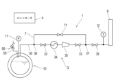
- FIG. 1 is a diagram showing a schematic configuration of a low-temperature gas release system according to an embodiment of the present disclosure.
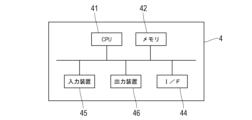
- FIG. 2 is a diagram illustrating an example of a hardware configuration of the controller.
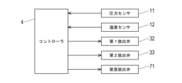
- FIG. 3 is a block diagram showing the configuration of a control system for the low-temperature gas release system.
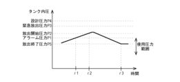
- FIG. 4 is a diagram illustrating an example of a change in the tank internal pressure over time.
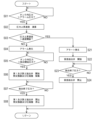
- FIG. 5 is a flow chart of the process of the controller which realizes the operating method according to the second embodiment.
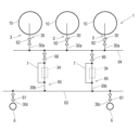
- FIG. 6 is a diagram showing a schematic configuration of a low-temperature gas release system according to the first modified example.
- FIG. 7 is a diagram showing a schematic configuration of a low-temperature gas release system according to the second modification.
- FIG. 8 is a diagram showing a schematic configuration of a low-temperature gas release system according to the third modification.
- FIG. 1 is a diagram showing a schematic configuration of a low-temperature gas discharge system 1 according to one embodiment of the present disclosure.
- the low-temperature gas discharge system 1 shown in FIG. 1 discharges boil-off gas generated in a liquefied gas tank 10 from a discharge tower 6 to the atmosphere.
- the liquefied gas tank 10 contains low-temperature liquefied gas such as liquid hydrogen or liquefied natural gas.
- This low-temperature gas discharge system 1 is provided in a land structure having a liquefied gas tank 10, or in a marine structure such as a floating structure or a ship.
- the liquefied gas tank 10 is provided with an emergency vent line 55 independent of the low-temperature gas discharge system 1.
- the emergency vent line 55 is provided with an automatic safety valve 56. However, the emergency vent line 55 may be combined with the low-temperature gas discharge system 1.
- the low-temperature gas release system 1 comprises a release line 3, a release tower 6, and a controller 4.
- the release line 3 guides the boil-off gas generated in the liquefied gas tank 10 from the liquefied gas tank 10 to the release tower 6.
- the controller 4 controls the low-temperature gas release system 1.
- the discharge line 3 has a main discharge line 30 that connects the gas phase in the liquefied gas tank 10 to the discharge tower 6.
- the main discharge line 30 is composed of low-temperature resistant piping such as double piping.
- a first discharge valve 32 and a second discharge valve 33 are provided in the main discharge line 30. Both the first discharge valve 32 and the second discharge valve 33 are normally closed opening/closing valves that open and close the flow path of the main discharge line 30.
- a heat exchanger 34 and a compressor 35 are provided downstream of the first discharge valve 32 and upstream of the second discharge valve 33. However, the compressor 35 may be omitted.
- the boil-off gas flowing through the main discharge line 30 is heated to a predetermined discharge temperature while passing through the heat exchanger 34.
- This discharge temperature is an arbitrary temperature.
- the discharge temperature is not particularly limited, but from the viewpoint of suppressing the generation of liquid air near the outlet of the discharge tower 6, a temperature higher than the boiling point of liquid oxygen is preferable.
- the heat exchange method of the heat exchanger 34 is not particularly limited, and a known heat exchange method such as a shell-and-tube method or a fin plate method may be adopted.
- the compressor 35 is arranged upstream or downstream of the heat exchanger 34 in the main discharge line 30. By operating the compressor 35, the boil-off gas flowing through the main discharge line 30 is pressure-sent to the discharge tower 6.
- the upstream end of the bypass line 7 is connected to the first connection part 36 upstream of the first discharge valve 32.
- the downstream end of the bypass line 7 is connected to the second connection part 37 downstream of the second discharge valve 33.
- the bypass line 7 guides the boil-off gas that has flowed into the main discharge line 30 to the discharge tower 6 without passing through the first discharge valve 32, the heat exchanger 34, the compressor 35, and the second discharge valve 33.
- the bypass line 7 is connected to the discharge line 3, but the bypass line 7 may directly connect the liquefied gas tank 10 and the discharge tower 6 without passing through the discharge line 3.
- the bypass line 7 is provided with an emergency release valve 71.
- the emergency release valve 71 is a normally closed opening/closing valve that opens and closes the flow path of the bypass line 7.
- one emergency release valve 71 is provided in the bypass line 7, but two or more emergency release valves 71 may be provided in the bypass line 7 in case of valve leakage or damage.
- the low-temperature gas discharge system 1 having the above configuration may be configured such that the discharge tower 6 from which the boil-off gas is discharged can be selected from among a plurality of discharge towers 6.
- the structure 100 has a plurality of liquefied gas tanks 10, and the low-temperature gas discharge system 1 has a plurality of discharge lines 3 and a plurality of discharge towers 6.
- the number of liquefied gas tanks 10 and the number of discharge towers 6 may be different.
- Each of the plurality of liquefied gas tanks 10 is connected to the upstream portion 30a of the main discharge line 30.
- Each of the upstream portions 30a of the plurality of main discharge lines 30 is connected to one hub 64 via an on-off valve 62.
- each of the plurality of discharge towers 6 is connected to one hub 63 via the downstream portion 30c of the main discharge line 30 and an on-off valve 61.
- the hubs 63 and 64 are connected by one or more shared lines 65.
- Each of the shared lines 65 has a midstream portion 30b of the main discharge line 30, a heat exchanger 34 through which the midstream portion 30b of the main discharge line 30 passes, a bypass line 7 connected to the midstream portion 30b of the main discharge line 30 so as to bypass the heat exchanger 34, and an on-off valve 66.
- the discharge line 3 connected to each liquefied gas tank 10 is composed of an upstream portion 30a of the main discharge line 30, a hub 64, at least one shared line 65, a hub 63, and a downstream portion 30c of the main discharge line 30.
- By opening and closing the on-off valve 61 it is possible to select the discharge tower 6 connected to the discharge line 3, i.e., one or more discharge towers 6 from which the boil-off gas is discharged.
- By opening and closing the on-off valve 66 it is possible to arbitrarily select the shared line 65 to be used, i.e., the heat exchanger 34 to be used. In other words, one or more heat exchangers 34 are shared by multiple discharge lines 3.
- a structure 100 including a liquefied gas tank 10 includes a discharge line 3 and a loading gas line 5 for transporting boil-off gas of liquefied gas from the liquefied gas tank 10 to the outside.
- the loading gas line 5 is composed of piping, etc.
- the loading gas line 5 is provided with a first release valve 32, a heat exchanger 34, a compressor 35, and a loading valve 52.
- the loading gas line 5 shares a part of the main discharge line 30, and the first release valve 32, the heat exchanger 34, and the compressor 35 arranged in the main discharge line 30 with the discharge line 3.
- a part 51 of the gas line 5 for loading which sends out the boil-off gas to the outside, is connected to the connection part 57 between the compressor 35 and the second discharge valve 33 of the main discharge line 30, and a loading valve 52 is disposed in the part 51 of the gas line 5 for loading.
- the loading valve 52 is a normally closed valve that opens and closes the flow path of the gas line 5 for loading.
- the heat exchanger 34 when the second discharge valve 33 is closed and the first discharge valve 32 and the loading valve 52 are open, the heat exchanger 34 functions as a loading heat exchanger of the gas line 5 for loading, and the compressor 35 functions as a loading compressor of the gas line 5 for loading. Also, when the first discharge valve 32 and the second discharge valve 33 are open and the loading valve 52 is closed, the heat exchanger 34 functions as a heat exchanger of the discharge line 3, and the compressor 35 functions as a compressor of the discharge line 3.
- piping and equipment may also be shared between the fuel gas line that sends the boil-off gas of the liquefied gas tank 10 as fuel to the combustion equipment and the discharge line 3.
- a part 51 of the fuel gas line that sends the boil-off gas to the combustion equipment is connected to the connection part 57 between the compressor 35 and the second discharge valve 33 of the main discharge line 30 shown in FIG. 7 instead of a part of the cargo gas line 5.
- the heat exchanger 34 functions as a fuel heat exchanger for the fuel gas line
- the compressor 35 functions as a fuel compressor for the fuel gas line.
- the controller 4 is a so-called computer, and includes a CPU (Central Processing Unit) 41, a memory 42, an I/F 44 for connecting to the discharge valves 32, 33, 71, the heat exchanger 34, the compressor 35, various instruments, and a communication network by radio or wireless communication, an input device 45 such as a mouse, keyboard, or touch panel, and an output device 46 such as a liquid crystal display or speaker.
- a CPU Central Processing Unit
- I/F 44 for connecting to the discharge valves 32, 33, 71, the heat exchanger 34, the compressor 35, various instruments, and a communication network by radio or wireless communication
- an input device 45 such as a mouse, keyboard, or touch panel
- an output device 46 such as a liquid crystal display or speaker.
- Each function of the controller 4, which will be described later, can be realized by loading a specific program stored in an auxiliary storage device or the like into the memory 42 and executing it by the CPU 41. Note that the above-mentioned specific program may be downloaded to the controller 4 from a network
- the functions of the controller 4 disclosed herein can be performed using circuits or processing circuits including general purpose processors, special purpose processors, integrated circuits, ASICs (Application Specific Integrated Circuits), conventional circuits, and/or combinations thereof configured or programmed to perform the disclosed functions.
- Processors are considered processing circuits or circuits because they include transistors and other circuitry.
- a circuit, unit, or means is hardware that performs the recited functions.
- the hardware may be hardware disclosed herein or other known hardware that is programmed or configured to perform the recited functions. Where the hardware is a processor, which is considered a type of circuit, the circuit, means, or unit is a combination of hardware and software, and the software is used to configure the hardware and/or the processor.
- FIG. 3 is a block diagram showing the configuration of the control system of the low-temperature gas release system 1. As shown in FIG. 3, the first release valve 32, the second release valve 33, and the emergency release valve 71 are connected to the controller 4, and the controller 4 opens and closes the first release valve 32, the second release valve 33, and the emergency release valve 71.
- a pressure sensor 11 and a temperature sensor 12 are connected to the controller 4, and detection data is output from these instruments to the controller 4.
- the pressure sensor 11 detects the pressure in the space containing the liquefied gas in the liquefied gas tank 10 (hereinafter referred to as the "tank pressure").
- the temperature sensor 12 detects the temperature of the boil-off gas flowing into the release tower 6. In this embodiment, the temperature sensor 12 is located downstream of the second connection part 37 of the main release line 30, but the temperature sensor 12 may also be located in the release tower 6.
- the controller 4 monitors the pressure inside the tank detected by the pressure sensor 11 while the liquefied gas is stored in the liquefied gas tank 10. As shown in FIG. 4, the controller 4 stores the operating pressure range of the liquefied gas tank 10, the alarm pressure P1, the release start pressure P2, the emergency release pressure P3, the design pressure P4 of the liquefied gas tank 10, and the release end pressure P5.
- the emergency release pressure P3 is equal to or lower than the design pressure P4
- the release start pressure P2 is lower than the emergency release pressure P3
- the alarm pressure P1 is equal to or lower than the release start pressure P2
- the release end pressure P5 is lower than the alarm pressure P1 (P4 ⁇ P3>P2 ⁇ P1>P5).
- the release end pressure P5 is a value within the operating pressure range of the liquefied gas tank 10.
- the alarm pressure P1 may be the upper limit of the operating pressure range of the liquefied gas tank 10 or a higher pressure.
- the alarm pressure P1 is a pressure threshold that triggers the operation of the low-temperature gas release system 1.
- it is preferable that the pressure at which the safety valve 56 of the emergency vent line 55 operates is lower than the design pressure P4 and higher than the emergency release pressure P3.
- the controller 4 monitors the temperature of the boil-off gas detected by the temperature sensor 12 while the boil-off gas is being released from the release tower 6. If the temperature of the boil-off gas detected by the temperature sensor 12 falls below the release temperature, measures such as increasing the heating temperature of the boil-off gas by the heat exchanger 34 and decreasing the amount of boil-off gas sent out by the compressor 35 are taken. If the temperature of the boil-off gas detected by the temperature sensor 12 exceeds the release temperature, measures such as decreasing the heating temperature of the boil-off gas by the heat exchanger 34 and increasing the amount of boil-off gas sent out by the compressor 35 are taken. In this way, the temperature of the boil-off gas detected by the temperature sensor 12 is maintained at the release temperature.
- the discharge line 3 of the low-temperature gas discharge system 1 configured as above has two flow paths: a "normal flow path” in which the boil-off gas discharged from the liquefied gas tank 10 is heated to a temperature higher than the boiling point of liquid oxygen by the heat exchanger 34 and then sent to the discharge tower 6, and an "emergency flow path” in which the boil-off gas is sent to the discharge tower 6 through the bypass line 7 that avoids the heat exchanger 34 and the compressor 35.
- the normal flow path is a flow path that passes through the main discharge line 30, and functions when the first release valve 32 and the second release valve 33 are opened and the emergency release valve 71 is closed.
- the emergency flow path is a flow path that passes through a part of the main discharge line 30 and the bypass line 7, and functions when the first release valve 32 and the second release valve 33 are closed and the emergency release valve 71 is opened.
- a third release valve 39 may be arranged downstream of the second connection part 37, which is the junction of the main discharge line 30 and the bypass line 7, in the discharge line 3.
- the third release valve 39 is an on-off valve that opens and closes in the same way as the first release valve 32 and the second release valve 33 when the normal flow path is in use, and opens and closes in the same way as the emergency release valve 71 when the emergency flow path is in use. In the event of a failure of either the second release valve 33 or the emergency release valve 71, the third release valve 39 takes over the function of the failed valve.
- the controller 4 controls the operation of the low-temperature gas discharge system 1 by opening and closing the valves 32, 33, and 71 to switch between a state in which the normal flow path functions and the emergency flow path does not function, a state in which the normal flow path does not function and the emergency flow path functions, and a state in which both the normal flow path and the emergency flow path do not function.
- a state in which both the normal flow path and the emergency flow path function there may also be a state in which both the normal flow path and the emergency flow path function.
- the tank internal pressure P increases due to boil-off gas of the liquefied gas contained in the liquefied gas tank 10. A part of the boil-off gas may be sent to a fuel consuming device as fuel.
- the controller 4 outputs an alarm from the output device 46. The alarm notifies the user of the release of the boil-off gas.
- the controller 4 When the tank pressure P reaches the discharge start pressure P2 (time t2), the controller 4 opens the first release valve 32 and the second release valve 33 and operates the compressor 35. Alternatively, when the pressure rise rate of the tank pressure P (i.e., the amount of pressure rise per unit time) reaches a predetermined discharge start pressure rise rate, the controller 4 opens the first release valve 32 and the second release valve 33 and operates the compressor 35.
- the controller 4 starts the heat exchanger 34 when or before the tank pressure P reaches the discharge start pressure P2.
- a stopped heat exchanger 34 requires a predetermined start-up time until it can heat the boil-off gas to the discharge temperature. Therefore, it is desirable to start the heat exchanger 34 before the tank pressure P reaches the discharge start pressure P2.
- the boil-off gas that flows from the liquefied gas tank 10 into the discharge line 3 is heated to the discharge temperature and sent to the discharge tower 6, from which it is released into the atmosphere. Since the boil-off gas released from the discharge tower 6 into the atmosphere has a higher boiling point than liquid oxygen, it is possible to prevent the generation of liquid oxygen, liquid nitrogen, and liquid air at the outlet of the discharge tower 6 or its surroundings.
- the tank pressure P gradually decreases due to the release of boil-off gas.
- the controller 4 stops the heat exchanger 34 and compressor 35 and closes the first release valve 32 and the second release valve 33.
- the controller 4 stops the heat exchanger 34 and compressor 35 and closes the first release valve 32 and the second release valve 33.
- the controller 4 stops the heat exchanger 34 and compressor 35 and closes the first release valve 32 and the second release valve 33.
- the controller 4 opens the emergency release valve 71.
- the controller 4 opens the emergency release valve 71 when the pressure rise rate (i.e., the amount of pressure rise per unit time) of the tank pressure P becomes equal to or higher than a predetermined emergency release rate threshold. Note that since the bypass line 7 upstream of the emergency release valve 71 is connected to the liquefied gas tank 10 via a portion of the main release line 30, the pressure of the bypass line 7 is substantially the same as the tank pressure P.
- the emergency release valve 71 By opening the emergency release valve 71, the emergency flow path of the release line 3 is opened, and a portion of the boil-off gas that has flowed into the release line 3 flows through the bypass line 7, i.e., to the release tower 6 without passing through the heat exchanger 34 and the compressor 35. In this way, when it becomes necessary to release boil-off gas urgently, a portion of the boil-off gas can be quickly released from the release tower 6 without passing through the heat exchanger 34 and the compressor 35, preventing an excessive increase in the tank pressure P.
- the opening and closing operations of the first release valve 32 and the second release valve 33 are controlled by the controller 4, but the opening and closing operations of at least one of the first release valve 32 and the second release valve 33 may be performed manually.
- the emergency release valve 71 is a control valve controlled by the controller 4, but it may be a manual valve or a safety valve that is automatically opened at emergency release pressure P3. In this case, when the emergency release valve 71 is open, the first release valve 32 and the second release valve 33 may be closed or open.
- Fig. 5 is a flow chart of the process of the controller 4 which realizes the operation method according to the second embodiment.
- the tank pressure P rises due to boil-off gas of the liquefied gas contained in the liquefied gas tank 10, and becomes an alarm pressure P1.
- the controller 4 monitors the tank pressure P, and when the tank pressure P reaches the alarm pressure P1 (step S01), calculates the pressure rise rate of the tank pressure P (step S02).
- the pressure rise rate of the tank pressure P can be obtained from the history of the tank pressure P.
- the controller 4 is provided with a speed threshold value for the pressure rise rate and stored in advance.
- the controller 4 compares the determined pressure rise rate with the speed threshold value (step S03), and if the pressure rise rate is less than the speed threshold value (NO in step S03), an alarm is output from the output device 46 (step S04). The alarm warns of the release of boil-off gas.
- the controller 4 opens the first and second discharge valves 32 and 33 and operates the compressor 35 (step S06).
- the controller 4 starts the heat exchanger 34 when or before the tank pressure P reaches the discharge start pressure P2.
- the liquefied gas tank 10 and the discharge tower 6 are connected through the steady-state flow path of the discharge line 3 and the heat exchanger 34 and compressor 35 are operated, the boil-off gas that flows from the liquefied gas tank 10 to the discharge line 3 is heated to the discharge temperature and sent to the discharge tower 6, from which it is discharged to the atmosphere.
- the controller 4 closes the first and second discharge valves 32 and 33 and stops the heat exchanger 34 and compressor 35 (step S08).
- step S03 if the pressure rise rate is equal to or higher than the rate threshold (YES in step S03), the controller 4 generates an alert from the output device 46 (step S21) and opens the emergency release valve 71 (step S22).
- the emergency release valve 71 may be opened after the tank pressure P exceeds the emergency release pressure P3.
- the emergency flow path of the release line 3 is opened, and the boil-off gas that has flowed into the release line 3 flows through the bypass line 7, i.e., without passing through the heat exchanger 34 and the compressor 35, to the release tower 6 and is released from the release tower 6 to the atmosphere.
- the controller 4 closes the emergency release valve 71 (step S24).
- the opening and closing operations of the first release valve 32, the second release valve 33, and the emergency release valve 71 are controlled by the controller 4, but the opening and closing operations of at least one of the first release valve 32, the second release valve 33, and the emergency release valve 71 may be performed manually.
- the controller 4 generates an alarm or alert at the appropriate time, and the operator can operate the manual valve in response to the alarm or alert.
- the heat exchanger 34 of the low-temperature gas discharge system 1 has uses other than heating the boil-off gas to be discharged, such as a heat exchanger for loading and unloading and a heat exchanger for fuel. Therefore, while the heat exchanger 34 is being used for purposes other than heating the boil-off gas to be discharged, such as loading and unloading and fuel supply, or while the heat exchanger 34 is stopped, it is possible to assume a situation in which the boil-off gas of the liquefied gas is discharged to the atmosphere from the liquefied gas tank 10.
- the boil-off gas of the liquefied gas is led from the liquefied gas tank 10 to the discharge tower 6 without passing through the heat exchanger 34 by using the emergency flow path, and the boil-off gas is discharged to the atmosphere.
- the controller 4 opens the emergency release valve 71 while closing the first release valve 32 and the second release valve 33.
- the controller 4 closes the emergency release valve 71. This allows the boil-off gas to be discharged to the atmosphere from the liquefied gas tank 10 without affecting the heating of the fuel or the loading and unloading.
- the emergency flow path can also be used as a flow path for releasing replacement gas during maintenance of the liquefied gas tank 10.
- the low-temperature gas discharge system 1 comprises: A system for discharging boil-off gas of liquefied gas from a liquefied gas tank 10 that stores liquefied gas into the atmosphere, A release tower 6; A discharge line 3 that guides the boil-off gas from the liquefied gas tank 10 to the discharge tower 6,
- the discharge line 3 includes a main discharge line 30 connecting the liquefied gas tank 10 and the discharge tower 6, a heat exchanger 34 arranged in the main discharge line 30 for heating the boil-off gas flowing through the main discharge line 30, discharge valves 32, 33 arranged in the main discharge line 30 for opening and closing the flow path, a bypass line 7 for directing the boil-off gas to the discharge tower 6 without passing through the discharge valves 32, 33 and the heat exchanger 34, and an emergency release valve 71 arranged in the bypass line 7 for opening and closing the flow path of the bypass line 7.
- the release line 3 has a flow path (i.e., a steady-state flow path) that sends the boil-off gas to the release tower 6 after heating it to a temperature higher than the boiling point of liquid oxygen in the heat exchanger 34, and a flow path (i.e., an emergency flow path) that sends the boil-off gas to the release tower 6 without passing through the heat exchanger 34.
- a flow path i.e., an emergency flow path
- boil-off gas with a temperature higher than the boiling point of liquid oxygen is released from the release tower 6, so that the released boil-off gas prevents liquefaction of the surface of the release tower 6 and the air (air contains oxygen and nitrogen) around the release tower 6.
- the boil-off gas can be released from the liquefied gas tank 10 without waiting for the heat exchanger 34 to start up, so that the tank internal pressure P of the liquefied gas tank 10 can be quickly reduced.
- the boil-off gas can be released from the liquefied gas tank 10 using the emergency flow path of the release line 3 without waiting for the release valves 32 and 33 to be operated or the heat exchanger 34 to be started up.
- the boil-off gas can be released from the liquefied gas tank 10 using the emergency flow path of the release line 3 without affecting the use of the heat exchanger 34 for other purposes.
- the emergency flow path of the release line 3 can be used not only for the above-mentioned emergency release, but also for gas replacement in the liquefied gas tank 10. In this way, in the low-temperature gas release system 1, the normal flow path and the emergency flow path of the release line 3 can be used separately depending on the purpose and situation.
- the low-temperature gas release system 1 according to the second item of the present disclosure is the low-temperature gas release system 1 according to the first item, which is provided with a plurality of release towers 6 that can be connected to the release line 3, and the plurality of release lines 3 have a switch (in the above embodiment, an opening/closing valve 61) that switches the flow path of the boil-off gas so that any one or more of the plurality of release towers 6 communicates with the liquefied gas tank 10.
- a switch in the above embodiment, an opening/closing valve 61
- the low-temperature gas discharge system 1 according to the third item of the present disclosure is the low-temperature gas discharge system 1 according to the first or second item, which is provided with a plurality of discharge lines 3 connected to different liquefied gas tanks 10, and the plurality of discharge lines 3 has a heat exchanger 34 shared by two or more discharge lines 3.
- heat exchangers 34 This allows the number of heat exchangers 34 to be reduced.
- the heat exchangers 34 included in the discharge line 3 can be selected arbitrarily.
- the low-temperature gas discharge system 1 according to the fourth item of the present disclosure is a low-temperature gas discharge system 1 according to any one of the first to third items, in which the discharge valves 32, 33 include a first discharge valve 32 arranged upstream of the heat exchanger 34 in the main discharge line 30, a second discharge valve 33 arranged downstream of the heat exchanger 34 in the main discharge line 30, and a third discharge valve 39 arranged downstream of the junction 37 of the main discharge line 30 and the bypass line 7.
- the double release valves 32, 33 By arranging the double release valves 32, 33 in the main release line 30 in this way, it is possible to prevent the boil-off gas from being released into the atmosphere or the outside air from flowing into the liquefied gas tank 10 due to leakage or damage from one of the valves.
- the third release valve 39 can perform the function of the valve when any of the other valves is opened due to a malfunction.
- the low-temperature gas discharge system 1 according to the fifth item of the present disclosure is a low-temperature gas discharge system 1 according to any one of the first to fourth items, which is provided with a temperature sensor 12 for detecting the temperature of the boil-off gas flowing into the discharge tower 6, and the heat exchanger 34 heats the boil-off gas so that the temperature of the boil-off gas detected by the temperature sensor 12 becomes a predetermined discharge temperature.
- the low-temperature gas release system 1 according to the sixth item of the present disclosure is a low-temperature gas release system 1 according to any one of the first to fifth items, in which the release valves 32, 33 are opened when the tank pressure P of the liquefied gas tank 10 exceeds a predetermined release start pressure P2 and closed when the tank pressure P reaches a predetermined release end pressure P5 due to the release of boil-off gas, or are opened when the pressure rise gradient of the tank pressure P of the liquefied gas tank 10 exceeds a predetermined release pressure rise gradient and closed when the pressure rise gradient of the tank pressure P reaches a predetermined release end pressure rise gradient due to the release of boil-off gas.
- the low-temperature gas release system 1 according to the seventh item of the present disclosure is the low-temperature gas release system 1 according to the sixth item, in which the emergency release valve 71 opens when the tank pressure P reaches a predetermined emergency release pressure P3 that is higher than the release start pressure P2.
- the low-temperature gas release system 1 according to the eighth item of the present disclosure is a low-temperature gas release system 1 according to any one of the first to fifth items, in which when the tank internal pressure P of the liquefied gas tank 10 is equal to or higher than a predetermined pressure threshold, the release valve is opened if the rate of increase of the tank internal pressure P is less than the predetermined rate threshold, and the emergency release valve 71 is opened if the rate of increase of the tank internal pressure P is equal to or higher than the rate threshold.
- the normal flow path and emergency flow path of the discharge line 3 can be used depending on the rate at which the internal tank pressure P of the liquefied gas tank 10 rises.
- the structure 100 according to the ninth aspect of the present disclosure is A liquefied gas tank 10 for storing liquefied gas; A low-temperature gas discharge system 1 according to any one of items 1 to 8; a cargo handling gas line 5 connected to the liquefied gas tank 10 and through which the boil-off gas of the liquefied gas flowing out from the liquefied gas tank 10 passes; A cargo handling heat exchanger 34 is disposed in the cargo handling gas line 5 and adjusts the temperature of the boil-off gas passing through the cargo handling gas line 5.
- the loading heat exchanger 34 also serves as the heat exchanger 34 of the low-temperature gas release system 1 .
- the heat exchanger 34 is shared between the loading gas line 5 and the discharge line 3, so a dedicated heat exchanger 34 for the discharge line 3 can be omitted.
- the structure 100 is A liquefied gas tank 10 for storing liquefied gas; A low-temperature gas discharge system 1 according to any one of items 1 to 8; a fuel gas line connected to the liquefied gas tank 10 and through which the boil-off gas of the liquefied gas flowing out from the liquefied gas tank 10 passes; a fuel heat exchanger 34 arranged in the fuel gas line and adjusting the temperature of the boil-off gas passing through the fuel gas line; The fuel heat exchanger 34 also serves as the heat exchanger 34 of the low-temperature gas discharge system 1 .
- the heat exchanger 34 is shared between the fuel gas line and the discharge line 3, so a dedicated heat exchanger 34 for the discharge line 3 can be omitted.
- a method for releasing a low-temperature gas includes: A method for releasing boil-off gas of liquefied gas from a liquefied gas tank 10 storing liquefied gas into the atmosphere, comprising the steps of: When the pressure in the liquefied gas tank 10 exceeds a predetermined release start pressure P2, the boil-off gas is heated in a heat exchanger 34 and then released into the atmosphere through a release tower 6, and when the pressure in the liquefied gas tank 10 exceeds a predetermined emergency release pressure P3 that is higher than the release start pressure P2, the boil-off gas is released into the atmosphere through the release tower 6 without passing through the heat exchanger 34.
- the emergency flow path of the release line 3 is used to quickly release the boil-off gas from the liquefied gas tank 10 and reduce the tank internal pressure P.
Landscapes
- Engineering & Computer Science (AREA)
- Mechanical Engineering (AREA)
- Chemical & Material Sciences (AREA)
- Combustion & Propulsion (AREA)
- Ocean & Marine Engineering (AREA)
- General Engineering & Computer Science (AREA)
- Filling Or Discharging Of Gas Storage Vessels (AREA)
Abstract
Description
放出塔と、
前記ボイルオフガスを前記液化ガスタンクから前記放出塔へ導く放出ラインと、を備え、
前記放出ラインは、前記液化ガスタンクと前記放出塔とを接続する放出主ラインと、前記放出主ラインに配置されて前記放出主ラインを流れる前記ボイルオフガスを加温する熱交換器と、前記放出主ラインに配置されて流路を開閉する放出弁と、前記ボイルオフガスを前記放出弁及び前記熱交換器を通さずに前記放出塔へ導くバイパスラインと、前記バイパスラインに配置されて前記バイパスラインの流路を開閉する緊急放出弁とを有するものである。
液化ガスを貯蔵する液化ガスタンクと、
上記の低温ガス放出システムと、
前記液化ガスタンクと接続され、前記液化ガスタンクから流れ出た前記液化ガスのボイルオフガスが通る荷役用ガスラインと、
前記荷役用ガスラインに配置され、前記荷役用ガスラインを通る前記ボイルオフガスを調温する荷役用熱交換器とを、備え、
前記荷役用熱交換器が前記低温ガス放出システムの前記熱交換器を兼ねるものである。
液化ガスを貯蔵する液化ガスタンクと、
上記の低温ガス放出システムと、
前記液化ガスタンクと接続され、前記液化ガスタンクから流れ出た前記液化ガスのボイルオフガスが通る燃料用ガスラインと、
前記燃料用ガスラインに配置され、前記燃料用ガスラインを通る前記ボイルオフガスを調温する燃料用熱交換器とを、備え、
前記燃料用熱交換器が前記低温ガス放出システムの前記熱交換器を兼ねるものである。
液化ガスを貯蔵する液化ガスタンクから前記液化ガスのボイルオフガスを大気へ放出する方法であって、
前記液化ガスタンク内の圧力が所定の放出開始圧力を超えたときに、前記ボイルオフガスを熱交換器で加温してから放出塔を通じて大気へ放出し、
前記液化ガスタンク内の圧力が前記放出開始圧力よりも高い所定の緊急放出開始圧力を超えたときに、前記ボイルオフガスを前記熱交換器を通さずに前記放出塔を通じて大気へ放出するものである。
図4に示すように、液化ガスタンク10に収容された液化ガスのボイルオフガスによって、タンク内圧力Pは上昇する。なお、ボイルオフガスの一部は、燃料として燃料消費機器へ送られてもよい。コントローラ4は、タンク内圧力Pがアラーム圧力P1となると(時刻t1)、出力装置46からアラームを出力する。アラームによって、ボイルオフガスの放出が予告される。
図5は、第2実施例に係る運転方法を実現するコントローラ4の処理の流れ図である。図5に示すように、タンク内圧力Pは、液化ガスタンク10に収容された液化ガスのボイルオフガスによって上昇して、アラーム圧力P1となる。コントローラ4は、タンク内圧力Pを監視しており、タンク内圧力Pがアラーム圧力P1となると(ステップS01)、タンク内圧力Pの圧力上昇速度を演算する(ステップS02)。タンク内圧力Pの圧力上昇速度は、タンク内圧力Pの履歴から求めることができる。
第3実施例において、低温ガス放出システム1の熱交換器34は、荷役用熱交換器や燃料用熱交換器などの、放出用ボイルオフガスの加温以外の用途を有する。したがって、熱交換器34が荷役や燃料供給などの放出用ボイルオフガスの加温以外に使用されている最中や、熱交換器34の停止中に、液化ガスタンク10から液化ガスのボイルオフガスを大気放出する事態が想定し得る。このような場合には、緊急時流路を利用して液化ガスタンク10から液化ガスのボイルオフガスを熱交換器34を通さずに放出塔6へ導き、ボイルオフガスを大気へ放出させる。具体的には、コントローラ4は、第1放出弁32及び第2放出弁33を閉止させた状態で、緊急放出弁71を開放する。コントローラ4は、ボイルオフガスの放出が終了すれば、緊急放出弁71を閉止する。これにより、燃料の加温や荷役に影響を与えることなく、液化ガスタンク10からボイルオフガスを大気放出できる。同様に、緊急時流路は、液化ガスタンク10のメンテナンス時に置換用ガスの放出流路としても利用できる。
本開示の第1の項目に係る低温ガス放出システム1は、
液化ガスを貯蔵する液化ガスタンク10から液化ガスのボイルオフガスを大気へ放出するシステムであって、
放出塔6と、
ボイルオフガスを液化ガスタンク10から放出塔6へ導く放出ライン3と、を備え、
放出ライン3は、液化ガスタンク10と放出塔6とを接続する放出主ライン30と、放出主ライン30に配置されて放出主ライン30を流れるボイルオフガスを加温する熱交換器34と、放出主ライン30に配置されて流路を開閉する放出弁32,33と、ボイルオフガスを放出弁32,33及び熱交換器34を通さずに放出塔6へ導くバイパスライン7と、バイパスライン7に配置されてバイパスライン7の流路を開閉する緊急放出弁71とを有するものである。
液化ガスを貯蔵する液化ガスタンク10と、
第1乃至8のいずれかの項目に係る低温ガス放出システム1と、
液化ガスタンク10と接続され、液化ガスタンク10から流れ出た液化ガスのボイルオフガスが通る荷役用ガスライン5と、
荷役用ガスライン5に配置され、荷役用ガスライン5を通るボイルオフガスを調温する荷役用熱交換器34とを、備え、
荷役用熱交換器34が低温ガス放出システム1の熱交換器34を兼ねるものである。
液化ガスを貯蔵する液化ガスタンク10と、
第1乃至8のいずれかの項目に係る低温ガス放出システム1と、
液化ガスタンク10と接続され、液化ガスタンク10から流れ出た液化ガスのボイルオフガスが通る燃料用ガスラインと、
燃料用ガスラインに配置され、燃料用ガスラインを通るボイルオフガスを調温する燃料用熱交換器34とを、備え、
燃料用熱交換器34が低温ガス放出システム1の熱交換器34を兼ねるものである。
液化ガスを貯蔵する液化ガスタンク10から液化ガスのボイルオフガス大気へ放出する方法であって、
液化ガスタンク10内の圧力が所定の放出開始圧力P2を超えたときに、ボイルオフガスを熱交換器34で加温してから放出塔6を通じて大気へ放出し、液化ガスタンク10内の圧力が放出開始圧力P2よりも高い所定の緊急放出圧力P3を超えたときに、ボイルオフガスを熱交換器34を通さずに放出塔6を通じて大気へ放出するものである。
Claims (11)
- 液化ガスを貯蔵する液化ガスタンクから前記液化ガスのボイルオフガスを大気へ放出するシステムであって、
放出塔と、
前記ボイルオフガスを前記液化ガスタンクから前記放出塔へ導く放出ラインと、を備え、
前記放出ラインは、前記液化ガスタンクと前記放出塔とを接続する放出主ラインと、前記放出主ラインに配置されて前記放出主ラインを流れる前記ボイルオフガスを加温する熱交換器と、前記放出主ラインに配置されて流路を開閉する放出弁と、前記ボイルオフガスを前記放出弁及び前記熱交換器を通さずに前記放出塔へ導くバイパスラインと、前記バイパスラインに配置されて前記バイパスラインの流路を開閉する緊急放出弁とを有する、
低温ガス放出システム。 - 前記放出ラインと接続可能な複数の前記放出塔を備え、前記放出ラインは複数の前記放出塔のうち任意の1つ以上を前記液化ガスタンクと連通させるように前記ボイルオフガスの流路を切り替える切替器を有する、
請求項1に記載の低温ガス放出システム。 - 互いに異なる前記液化ガスタンクと接続された複数の前記放出ラインを備え、複数の前記放出ラインは2つ以上の前記放出ラインで共有される前記熱交換器を有する、
請求項1又は2に記載の低温ガス放出システム。 - 前記放出弁は、前記放出主ラインにおいて前記熱交換器の上流に配置された第1放出弁と、前記放出主ラインにおいて前記熱交換器の下流に配置された第2放出弁と、前記放出主ラインと前記バイパスラインとの合流点の下流に配置された第3放出弁とを含む、
請求項1乃至3のいずれか一項に記載の低温ガス放出システム。 - 前記放出塔へ流入する前記ボイルオフガスの温度を検出する温度センサを備え、
前記熱交換器は、前記温度センサで検出される前記ボイルオフガスの温度が所定の放出温度となるように前記ボイルオフガスを加温する、
請求項1乃至4のいずれか一項に記載の低温ガス放出システム。 - 前記放出弁は、前記液化ガスタンクのタンク内圧力が所定の放出開始圧力を超えると開放され、前記ボイルオフガスの放出によって前記タンク内圧力が所定の放出終了圧力となると閉止される、又は、前記液化ガスタンクのタンク内圧力の圧力上昇速度が所定の放出圧力上昇速度を超えると開放され、前記ボイルオフガスの放出によって前記タンク内圧力の圧力上昇速度が所定の放出終了圧力上昇速度となると閉止される、
請求項1乃至5のいずれか一項に記載の低温ガス放出システム。 - 前記緊急放出弁は、前記タンク内圧力が前記放出開始圧力よりも高い所定の緊急放出開始圧力のときに開放される、
請求項6に記載の低温ガス放出システム。 - 前記液化ガスタンクのタンク内圧力が所定の圧力閾値以上のときに、前記タンク内圧力の上昇速度が所定の速度閾値未満の場合は前記放出弁が開放され、前記タンク内圧力の前記上昇速度が前記速度閾値以上の場合は前記緊急放出弁が開放される、
請求項1乃至5のいずれか一項に記載の低温ガス放出システム。 - 液化ガスを貯蔵する液化ガスタンクと、
請求項1乃至8のいずれか一項に記載の低温ガス放出システムと、
前記液化ガスタンクと接続され、前記液化ガスタンクから流れ出た前記液化ガスのボイルオフガスが通る荷役用ガスラインと、
前記荷役用ガスラインに配置され、前記荷役用ガスラインを通る前記ボイルオフガスを調温する荷役用熱交換器とを、備え、
前記荷役用熱交換器が前記低温ガス放出システムの前記熱交換器を兼ねる、
構造物。 - 液化ガスを貯蔵する液化ガスタンクと、
請求項1乃至8のいずれか一項に記載の低温ガス放出システムと、
前記液化ガスタンクと接続され、前記液化ガスタンクから流れ出た前記液化ガスのボイルオフガスが通る燃料用ガスラインと、
前記燃料用ガスラインに配置され、前記燃料用ガスラインを通る前記ボイルオフガスを調温する燃料用熱交換器とを、備え、
前記燃料用熱交換器が前記低温ガス放出システムの前記熱交換器を兼ねる、
構造物。 - 液化ガスを貯蔵する液化ガスタンクから前記液化ガスのボイルオフガスを大気へ放出する方法であって、
前記液化ガスタンク内の圧力が所定の放出開始圧力を超えたときに、前記ボイルオフガスを熱交換器で加温してから放出塔を通じて大気へ放出し、
前記液化ガスタンク内の圧力が前記放出開始圧力よりも高い所定の緊急放出開始圧力を超えたときに、前記ボイルオフガスを前記熱交換器を通さずに前記放出塔を通じて大気へ放出する、
低温ガス放出方法。
Priority Applications (4)
| Application Number | Priority Date | Filing Date | Title |
|---|---|---|---|
| PCT/JP2023/004138 WO2024166242A1 (ja) | 2023-02-08 | 2023-02-08 | 低温ガス放出システム、構造物、及び低温ガス放出方法 |
| KR1020257027094A KR20250135846A (ko) | 2023-02-08 | 2023-02-08 | 저온 가스 방출 시스템, 구조물 및 저온 가스 방출 방법 |
| CN202380093129.9A CN120641693A (zh) | 2023-02-08 | 2023-02-08 | 低温气体排出系统、构造物以及低温气体排出方法 |
| JP2024575939A JP7909051B2 (ja) | 2023-02-08 | 低温ガス放出システム、構造物、及び低温ガス放出方法 |
Applications Claiming Priority (1)
| Application Number | Priority Date | Filing Date | Title |
|---|---|---|---|
| PCT/JP2023/004138 WO2024166242A1 (ja) | 2023-02-08 | 2023-02-08 | 低温ガス放出システム、構造物、及び低温ガス放出方法 |
Publications (1)
| Publication Number | Publication Date |
|---|---|
| WO2024166242A1 true WO2024166242A1 (ja) | 2024-08-15 |
Family
ID=92262177
Family Applications (1)
| Application Number | Title | Priority Date | Filing Date |
|---|---|---|---|
| PCT/JP2023/004138 Ceased WO2024166242A1 (ja) | 2023-02-08 | 2023-02-08 | 低温ガス放出システム、構造物、及び低温ガス放出方法 |
Country Status (3)
| Country | Link |
|---|---|
| KR (1) | KR20250135846A (ja) |
| CN (1) | CN120641693A (ja) |
| WO (1) | WO2024166242A1 (ja) |
Citations (4)
| Publication number | Priority date | Publication date | Assignee | Title |
|---|---|---|---|---|
| DE102008061192A1 (de) * | 2008-12-09 | 2010-06-17 | Man Diesel Se | Gasversorgungsanlage für einen Antrieb |
| JP2018204721A (ja) * | 2017-06-06 | 2018-12-27 | 川崎重工業株式会社 | ガス放出システム |
| JP2019056381A (ja) * | 2017-09-19 | 2019-04-11 | 三井E&S造船株式会社 | ボイルオフガス処理システム |
| JP2021160619A (ja) * | 2020-04-01 | 2021-10-11 | 川崎重工業株式会社 | 船舶 |
-
2023
- 2023-02-08 CN CN202380093129.9A patent/CN120641693A/zh active Pending
- 2023-02-08 WO PCT/JP2023/004138 patent/WO2024166242A1/ja not_active Ceased
- 2023-02-08 KR KR1020257027094A patent/KR20250135846A/ko active Pending
Patent Citations (4)
| Publication number | Priority date | Publication date | Assignee | Title |
|---|---|---|---|---|
| DE102008061192A1 (de) * | 2008-12-09 | 2010-06-17 | Man Diesel Se | Gasversorgungsanlage für einen Antrieb |
| JP2018204721A (ja) * | 2017-06-06 | 2018-12-27 | 川崎重工業株式会社 | ガス放出システム |
| JP2019056381A (ja) * | 2017-09-19 | 2019-04-11 | 三井E&S造船株式会社 | ボイルオフガス処理システム |
| JP2021160619A (ja) * | 2020-04-01 | 2021-10-11 | 川崎重工業株式会社 | 船舶 |
Also Published As
| Publication number | Publication date |
|---|---|
| CN120641693A (zh) | 2025-09-12 |
| JPWO2024166242A1 (ja) | 2024-08-15 |
| KR20250135846A (ko) | 2025-09-15 |
Similar Documents
| Publication | Publication Date | Title |
|---|---|---|
| JP2016503150A (ja) | ボイルオフガスの再凝縮のためのシステム及び方法 | |
| JP2019049216A (ja) | 船舶 | |
| US20230375136A1 (en) | Fuel delivery system | |
| JP2024095550A (ja) | 燃料コンディショニングシステム | |
| KR101996288B1 (ko) | 선박의 증발가스 처리 시스템 및 방법 | |
| EP2676881A1 (en) | Aircraft comprising a cooling system for operation with a two-phase refrigerant | |
| GB2564879A (en) | Liquiefying a gaseous medium | |
| JP2023124764A (ja) | 浮体 | |
| KR20250135846A (ko) | 저온 가스 방출 시스템, 구조물 및 저온 가스 방출 방법 | |
| JP6959804B2 (ja) | 船舶およびlpg温度/圧力管理方法 | |
| WO2024166241A1 (ja) | 液体水素貯蔵設備、浮体構造物、及び多重殻タンクの槽間ガス供給方法 | |
| WO2025114686A1 (en) | A propulsion system for an aircraft and a method of power management system in an aircraft | |
| JP2018103954A (ja) | 船舶 | |
| US10870811B2 (en) | Method for operating fuel gas manufacturing device | |
| JP7837189B2 (ja) | 液化ガス貯蔵タンクのクールダウン方法 | |
| EP3435015A1 (en) | Liquiefying a gaseous medium | |
| JP7855080B2 (ja) | 液体水素タンク及びその運転方法 | |
| JP2019007511A (ja) | 液化ガス管理システム | |
| JP6722074B2 (ja) | 船舶 | |
| JP2026031231A (ja) | 液化ガス燃料タンク設備、及び液化ガス燃料タンクのイナーティング及びガスフリー方法 | |
| JP2026075374A (ja) | 水素ガス貯蔵装置 | |
| CN119821590B (zh) | 船舶及液货舱气压控制方法 | |
| US11761588B2 (en) | Device for transferring a fluid from a supply tank to a receiver tank | |
| JP7828838B2 (ja) | 液化ガス運搬船 | |
| CN114001272B (zh) | 一种lng过驳作业bog管理系统 |
Legal Events
| Date | Code | Title | Description |
|---|---|---|---|
| 121 | Ep: the epo has been informed by wipo that ep was designated in this application |
Ref document number: 23921074 Country of ref document: EP Kind code of ref document: A1 |
|
| WWE | Wipo information: entry into national phase |
Ref document number: 2024575939 Country of ref document: JP |
|
| WWE | Wipo information: entry into national phase |
Ref document number: 202380093129.9 Country of ref document: CN |
|
| ENP | Entry into the national phase |
Ref document number: 1020257027094 Country of ref document: KR Free format text: ST27 STATUS EVENT CODE: A-0-1-A10-A15-NAP-PA0105 (AS PROVIDED BY THE NATIONAL OFFICE) |
|
| WWE | Wipo information: entry into national phase |
Ref document number: 1020257027094 Country of ref document: KR |
|
| NENP | Non-entry into the national phase |
Ref country code: DE |
|
| WWP | Wipo information: published in national office |
Ref document number: 202380093129.9 Country of ref document: CN |
|
| 122 | Ep: pct application non-entry in european phase |
Ref document number: 23921074 Country of ref document: EP Kind code of ref document: A1 |