WO2024166202A1 - 電池劣化状態推定装置及び電池劣化状態推定方法 - Google Patents
電池劣化状態推定装置及び電池劣化状態推定方法 Download PDFInfo
- Publication number
- WO2024166202A1 WO2024166202A1 PCT/JP2023/003966 JP2023003966W WO2024166202A1 WO 2024166202 A1 WO2024166202 A1 WO 2024166202A1 JP 2023003966 W JP2023003966 W JP 2023003966W WO 2024166202 A1 WO2024166202 A1 WO 2024166202A1
- Authority
- WO
- WIPO (PCT)
- Prior art keywords
- battery
- storage
- secondary battery
- profile
- degradation state
- Prior art date
- Legal status (The legal status is an assumption and is not a legal conclusion. Google has not performed a legal analysis and makes no representation as to the accuracy of the status listed.)
- Ceased
Links
Images


Classifications
-
- H—ELECTRICITY
- H01—ELECTRIC ELEMENTS
- H01M—PROCESSES OR MEANS, e.g. BATTERIES, FOR THE DIRECT CONVERSION OF CHEMICAL ENERGY INTO ELECTRICAL ENERGY
- H01M10/00—Secondary cells; Manufacture thereof
- H01M10/42—Methods or arrangements for servicing or maintenance of secondary cells or secondary half-cells
- H01M10/48—Accumulators combined with arrangements for measuring, testing or indicating the condition of cells, e.g. the level or density of the electrolyte
-
- H—ELECTRICITY
- H02—GENERATION; CONVERSION OR DISTRIBUTION OF ELECTRIC POWER
- H02J—ELECTRIC POWER NETWORKS; CIRCUIT ARRANGEMENTS OR SYSTEMS FOR SUPPLYING OR DISTRIBUTING ELECTRIC POWER; SYSTEMS FOR STORING ELECTRIC ENERGY
- H02J7/00—Circuit arrangements for charging or discharging batteries or for supplying loads from batteries
Definitions
- the present invention relates to a battery degradation state estimation device and a battery degradation state estimation method.
- the secondary use destination (for use as a stationary power source or a mobile power source, etc.) is determined according to the state of the secondary battery at the time when its use as an on-board battery (primary use) ends.
- WO2021/193006A1 discloses a battery reuse support system that estimates the deterioration state of a battery at the planned time of sale obtained from the user based on the deterioration state of the battery while the vehicle is in use (during primary use), determines multiple product types (secondary use destinations) into which the battery can be installed from the estimated deterioration state, calculates the transaction price (predicted selling price) of the battery for each determined product type, and notifies the user of the calculated price.
- the deterioration state of the battery from the primary use to the planned sale date is calculated based on a predetermined uniform deterioration line.
- a certain storage period e.g., several months to several years
- the secondary battery is not generally charged or discharged, but deterioration of the secondary battery progresses due to storage deterioration.
- the deterioration progress during the storage period is also uniformly estimated using the same deterioration line as during primary use. For this reason, there is a risk that the estimated value of the deterioration state of the secondary battery at the start of secondary use may deviate from the actual value, and its reliability may not be ensured.
- the present invention therefore aims to further improve the accuracy of estimating the degradation state of a secondary battery when it is provided to a secondary user.
- the battery degradation state estimation device that estimates the degradation state of a secondary battery installed in a vehicle at the time of providing it for secondary use.
- the battery degradation state estimation device includes a profile calculation unit that calculates a storage degradation profile that represents the progression of degradation during the storage period from the end of the secondary battery's primary use until it is provided for secondary use, a data generation unit that generates predicted battery state data including a predicted degradation state at the time of providing it for secondary use based on the storage degradation profile, and a data output unit that outputs the predicted battery state data to a specified external device.
- FIG. 1 is a block diagram showing a main configuration of a battery degradation state estimating system common to all the embodiments.
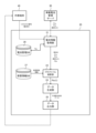
- FIG. 2 is a block diagram showing details of the battery degradation state estimating system according to the first embodiment.
- FIG. 3 is a flowchart illustrating each process performed by the battery degradation state estimating device.
- FIG. 4 is a flow chart for explaining the deterioration profile calculation.
- FIG. 5 is a block diagram showing a specific configuration for realizing the deterioration profile calculation.
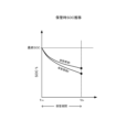
- FIG. 6 is a diagram showing an example of a change in SOC during storage.
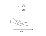
- FIG. 7 is a diagram showing an example of a storage deterioration profile for each secondary battery.
- FIG. 8 is a block diagram showing details of a battery degradation state estimating system according to the second embodiment.
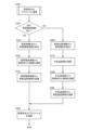
- FIG. 9 is a flowchart illustrating the deterioration profile calculation.
- FIG. 10 is a diagram showing an example of changes in outside air temperature.
- FIG. 11 is a block diagram showing a
- FIG. 1 is a diagram for explaining the configuration of a battery degradation state estimation system 10 according to this embodiment.
- FIG. 2 is a block diagram showing the details of the battery degradation state estimation system 10.
- the battery degradation state estimation system 10 of this embodiment is configured as a system for predicting the degradation state of a secondary battery B (B1, B2, ... Bn) mounted on each vehicle V (V1, V2, ... Vn in FIG. 1) when the secondary battery B is provided to a predetermined secondary use destination (reuse destination), and for providing information (data) related to the degradation state to the outside.
- each vehicle V of this embodiment is assumed to be an electric vehicle or a hybrid vehicle equipped with an on-board battery.
- the battery degradation state estimation system 10 mainly comprises a battery degradation state estimation device 20, an in-vehicle battery management server 30, in-vehicle terminals VT (VT1, VT2, ... VTn) mounted on each vehicle V, and an external terminal 40.
- the battery degradation state estimation device 20 is connected to the vehicle-mounted battery management server 30, each vehicle-mounted terminal VT, and the external terminal 40 via a specified network 100 so that they can communicate with each other.
- the network 100 is composed of various hardware and communication protocols to enable communication between the battery degradation state estimation device 20, the vehicle-mounted battery management server 30, each vehicle-mounted terminal VT, and the external terminal 40.
- the communication function between the vehicle-mounted battery management server 30 or the external terminal 40 and the battery degradation state estimation device 20 is realized by various communication protocols such as TCP/IP for wide area network communication.
- the communication function between the vehicle-mounted terminal VT and the battery degradation state estimation device 20 is realized by various communication protocols for realizing so-called telematics (mobile communication system).
- the battery degradation state estimation device 20 is configured by a computer equipped with various calculation/control devices, storage devices, and input/output devices, and storing a program for executing a desired calculation/control process in the storage device.
- the battery degradation state estimation device 20 receives a request signal including identification information (hereinafter also simply referred to as "battery ID") of the target secondary battery Bk from the external terminal 40
- the battery degradation state estimation device 20 acquires various input information specified by the battery ID from the in-vehicle battery management server 30.
- the battery degradation state estimation device 20 generates predicted battery state data of the secondary battery Bk linked to the battery ID based on the various input information.
- the battery degradation state estimation device 20 outputs and transmits the generated predicted battery state data to the external terminal 40.
- the battery degradation state estimation device 20 has a battery information acquisition unit 21, a profile calculation unit 23, a data generation unit 24, a data output unit 25, a battery management DB 26, and a storage information DB 27.
- the battery information acquisition unit 21 When the battery information acquisition unit 21 receives a request signal including a battery ID linked to the secondary battery Bk from the external terminal 40, it refers to the battery management DB 26 and extracts the vehicle Vk (vehicle ID) linked to the battery ID and the scheduled secondary use start date t2e of the secondary battery Bk.
- the scheduled secondary use start date t2e is the date on which the secondary battery Bk is scheduled to be provided to a secondary use destination, and is set in advance.
- the battery information acquisition unit 21 receives information on the secondary battery Bk mounted on the vehicle Vk from the in-vehicle battery management server 30, using the identified vehicle ID as a key.
- the information received from the in-vehicle battery management server 30 includes the primary use start date t 1s , primary use end date t 1e , and final SOC (State of Charge) of the secondary battery Bk.
- the primary use start date t 1s is the date on which the secondary battery Bk actually starts to be used as an in-vehicle battery, such as the product shipping date of the vehicle Vk or the date on which the user purchases the vehicle Vk.
- the primary use end date t 1e is the date on which the use as an in-vehicle battery ends.
- the primary use end date t 1e in this embodiment is defined as the date on which the user completes procedures such as a sales contract for the vehicle Vk or the secondary battery Bk and removes the secondary battery Bk from the vehicle Vk.
- the final SOC is the charging rate (SOC) of the secondary battery Bk on the primary use end date t 1e .
- the battery information acquisition unit 21 outputs data linking the battery ID with the primary use start date t 1s , primary use end date t 1e , final SOC, and scheduled secondary use start date t 2e to the profile calculation unit 23 .
- the profile calculation unit 23 inputs the primary use start date t 1s , the primary use end date t 1e , the final SOC, and the secondary use scheduled start date t 2e to calculate a storage deterioration profile P Bk (t) of the secondary battery Bk associated with the battery ID.
- the storage deterioration profile P Bk (t) is a function that represents the transition of the deterioration state (health state) of the secondary battery Bk during the storage period [t 1e , t 2e ] from the primary use end date t 1e to the secondary use scheduled start date t 2e .
- the SOH State Of Health
- the SOH is defined as the ratio (capacity maintenance rate) of the current battery capacity (full charge capacity) to the initial battery capacity (full charge capacity) (for example, the primary use start date t 1s ).
- the profile calculation unit 23 reads out the storage environment information of the secondary battery Bk from the storage information DB 27 using the battery ID as a key.
- the storage environment information includes information on the storage location (facility) of the secondary battery Bk.
- the storage environment information preferably includes physical quantities (such as temperature or humidity during storage) that affect the self-discharge rate (rate of decrease in SOC) of the secondary battery Bk.
- the storage environment information preferably includes the ambient temperature (storage temperature Ts) of the secondary battery Bk during storage, or information required to estimate the storage temperature Ts.
- the storage environment information preferably includes the storage management temperature of the secondary battery Bk for each storage facility. Details of the processing in the profile calculation unit 23 will be described later.
- the data generation unit 24 generates predicted battery state data based on the storage deterioration profile P Bk (t) calculated by the profile calculation unit 23.
- the data generation unit 24 generates predicted battery state data including the entire storage deterioration profile P Bk (t) or at least the value of the storage deterioration profile P Bk (t) on the scheduled secondary utilization start date t 2e (predicted SOH).
- the data output unit 25 outputs the predicted battery state data to the external terminal 40.
- the data output unit 25 may have a so-called SaaS (Software as a Service) function of displaying information included in the predicted battery state data on the display screen of the external terminal 40 in a desired display format.
- SaaS Software as a Service
- the battery management DB 26 is a database that stores a battery ID uniquely assigned to each secondary battery B, linked to a vehicle ID assigned to each vehicle V.
- the storage information DB 27 is a database that stores the battery ID of each secondary battery B, linked to the respective storage environment information.
- the in-vehicle battery management server 30 is a server that manages each secondary battery B mounted on each vehicle V included in the battery degradation state estimation system 10.
- the in-vehicle battery management server 30 of this embodiment has a database (not shown) that stores the primary use start date t 1s , primary use end date t 1e , and final SOC for each secondary battery B in association with the vehicle ID of each vehicle V.
- the in-vehicle battery management server 30 receives a signal including the vehicle ID from the battery information acquisition unit 21, it reads out the primary use start date t 1s , primary use end date t 1e , and final SOC of the secondary battery Bk associated with the vehicle ID from the database, and transmits them to the battery degradation state estimation device 20.
- the external terminal 40 is a terminal operated by an intermediary (such as a storage facility management company) involved in providing the secondary battery Bk to a secondary user, or a secondary user company (such as a recycler), and is composed of a mobile terminal such as a smartphone or a tablet terminal, or a personal computer such as a notebook computer (laptop) or desktop computer.
- an intermediary such as a storage facility management company
- a secondary user company such as a recycler
- the external terminal 40 when it detects an input operation by a specific operator requesting the provision of predicted battery state data, it generates a request signal including a battery ID and transmits it to the battery degradation state estimation device 20.
- the external terminal 40 also has a display unit (display screen) for displaying various information included in the predicted battery state data received from the battery degradation state estimation device 20 in response to the transmission of the request signal in a specific manner according to a program stored in its own memory area or through processing by the battery degradation state estimation device 20.
- the on-board terminal VTk is an on-board computer that is installed in the vehicle Vk and provides the battery degradation state estimating device 20 with necessary information.
- the specific processing performed by the battery degradation state estimation device 20 is described in more detail below.
- FIG. 3 is a flowchart explaining the details of the processing performed by the battery degradation state estimation device 20.
- step S100 the battery information acquisition unit 21 uses the battery ID received from the external terminal 40 as a key to acquire the secondary use start date t 2e of the secondary battery Bk linked to that battery ID.
- step S200 the battery information acquisition unit 21 acquires from the in-vehicle battery management server 30 the primary use start date t 1s , the primary use end date t 1e , and the final SOC of the secondary battery Bk associated with the battery ID.
- step S300 the profile calculation unit 23 calculates the storage deterioration profile P Bk (t) of the secondary battery Bk.
- FIG. 4 is a flowchart explaining the degradation profile calculation
- FIG. 5 is a block diagram showing a specific configuration for realizing the degradation profile calculation.
- the profile calculation unit 23 extracts storage environment information of the corresponding secondary battery Bk from the storage information DB 27 using the battery ID as a key (S310).
- the profile calculation unit 23 calculates the SOC transition during storage based on the storage environment information, the final SOC, the primary use end date t1e , and the secondary use start date t2e (S320).
- the SOC transition during storage in this embodiment is given as a function representing the change over time in the SOC of the secondary battery Bk during the storage period [ t1e , t2e ].
- FIG. 6 is a diagram showing an example of SOC transition during storage.
- the SOC characteristic over time of secondary battery Bk during the storage period [t 1e , t 2e ] may change in different storage environments (storage environments I and II in FIG. 5 ). Therefore, by calculating the SOC transition during storage with reference to storage environment information, it is possible to reflect the difference in the SOC characteristic over time according to the storage environment (temperature, humidity, etc.) in the calculation.
- the secondary battery Bk is basically not charged or discharged, and therefore, the change (decrease) in the SOC of the secondary battery Bk during the storage period [t 1e , t 2e ] can be said to indicate the self-discharge amount of the secondary battery Bk.
- the profile calculation unit 23 calculates the storage temperature transition Ts(t) based on the storage environment information, the primary use end date t 1e , and the secondary use start date t 2e (S330).
- the storage temperature transition Ts(t) in this embodiment is given as a function that represents the change over time in the storage temperature Ts of the secondary battery Bk during the storage period [t 1e , t 2e ]. Note that in cases where the storage temperature Ts does not change over time, such as when the temperature is managed to be constant depending on the storage facilities, the storage temperature transition Ts(t) can be set to a constant.
- the profile calculation unit 23 calculates the storage deterioration profile P Bk (t) from the storage SOC transition and the storage temperature transition Ts(t) (S340).
- the profile calculation unit 23 calculates the first unit deterioration amount ⁇ D1(t) by multiplying the storage SOC transition by a predetermined gain K1 (S3401).
- the first unit deterioration amount ⁇ D1(t) is a function representing the deterioration amount (decrease amount of SOH) per unit time (unit number of days) according to the SOC change of the secondary battery Bk during the storage period [t 1e , t 2e ].
- the deterioration amount due to storage deterioration of the secondary battery Bk is proportional to the square root of the number of days t elapsed from the primary use end date t 1e as a base point, and increases as the SOC of the secondary battery Bk increases.
- the gain K1 is set to an appropriate value for determining the first unit deterioration amount ⁇ D1(t) taking into consideration the number of days elapsed t and the change (decrease) of the SOC according to the number of days elapsed t.
- the profile calculation unit 23 also calculates the second unit degradation amount ⁇ D2(t) by multiplying the storage temperature transition Ts(t) by a predetermined gain K2 (S3402).
- the second unit degradation amount ⁇ D2(t) is a function that represents the degradation amount (amount of reduction in SOH) per unit time (unit number of days) according to the change in the storage temperature Ts of the secondary battery Bk during the storage period [t 1e , t 2e ].
- the degradation amount due to storage degradation of the secondary battery Bk is proportional to the square root of the number of days t elapsed from the primary use end date t 1e as the base point, and increases as the storage temperature Ts increases. Therefore, the gain K2 is set to an appropriate value for determining the second unit degradation amount ⁇ D2(t) taking into consideration the number of days elapsed t and the change in the storage temperature Ts according to the number of days elapsed t.
- the profile calculation unit 23 calculates the sum (integral value ) of the products of the first unit degradation amount ⁇ D1(t) and the second unit degradation amount ⁇ D2(t) at any time point of the number of days elapsed from the primary usage end date t 1e as the storage degradation degree D(t) (S3403). That is, the storage degradation degree D(t) is determined as a function representing the amount of reduction in SOH from the primary usage end date t 1e to the number of days elapsed.
- a calculation logic can be adopted that corrects the storage deterioration degree D(t) obtained by the calculation logic of S3401 to S3403 so that it is larger the longer the primary usage period [t 1s , t 1e ].
- the profile calculation unit 23 subtracts the storage deterioration degree D(t) from the SOH of the secondary battery Bk on the primary use end date t1e (hereinafter also referred to as "initial SOH") to obtain a storage deterioration profile P Bk (t) (S3404). That is, the storage deterioration profile P Bk (t) is determined as a function representing the change over time in the SOH of the secondary battery Bk from the primary use end date t1e to the number of days that have elapsed since.
- a storage deterioration profile P Bk (t) specific to the secondary battery Bk can be obtained. That is, in the case of each of the secondary batteries B1, B2, B3, ..., a storage deterioration profile P B1 (t), P B2 (t), P B3 (t), ... specific to each of the secondary batteries B1, B2, B3, ... can be determined.
- FIG. 7 shows examples of storage deterioration profiles P B1 (t), P B2 (t), and P B3 (t) for each of the secondary batteries B1, B2, and B3.
- step S400 the data generator 24 generates predicted battery state data from the storage deterioration profile P Bk (t) and the data output unit 25 outputs the generated predicted battery state data to the external terminal 40.
- a battery degradation state estimation device 20 that estimates the degradation state of a secondary battery Bk mounted on a vehicle Vk at the time of being provided for secondary use.
- the battery degradation state estimation device 20 includes a profile calculation unit 23 that calculates a storage degradation profile P Bk (t) that represents a degradation progression during a storage period [t 1e , t 2e ] from the end of primary use of the secondary battery Bk until it is provided for secondary use, a data generation unit 24 that generates predicted battery state data including a predicted degradation state (predicted SOH) at the time of being provided for secondary use based on the storage degradation profile P Bk (t), and a data output unit 25 that outputs the predicted battery state data to a predetermined external device (external terminal) 40.
- this embodiment further includes an acquisition unit (battery state acquisition unit 21) that acquires the primary use end date t1e and the scheduled secondary use start date t2e of the secondary battery Bk.
- the profile calculation unit 23 then calculates a storage deterioration profile P Bk (t) based on the primary use end date t1e , the scheduled secondary use start date t2e , and the storage environment information of the secondary battery Bk.
- the battery information acquisition unit 21 further acquires the primary usage start date t 1s of the secondary battery Bk.
- the profile calculation unit 23 then calculates the storage deterioration profile P Bk (t) by referring to the primary usage period [t 1s , t 1e ] determined from the primary usage start date t 1s and the primary usage end date t 1e .
- the battery information acquisition unit 21 further acquires the final charging rate (final SOC), which is the charging rate of the secondary battery Bk on the primary use end date t 1e .
- the profile calculation unit 23 calculates a storage charging rate transition (storage SOC transition) that represents the change over time of the charging rate (SOC) during the storage period [t 1e , t 2e ] based on the storage environment information, the final SOC, the primary use end date t 1e , and the secondary use scheduled start date t 2e .
- the profile calculation unit 23 calculates a storage temperature transition Ts(t) that represents the change over time of the storage temperature Ts of the secondary battery Bk during the storage period [t 1e , t 2e ] based on the storage environment information, the primary use end date t 1e , and the secondary use scheduled start date t 2e . Furthermore, the profile calculation unit 23 calculates a storage deterioration profile P Bk (t) based on the storage SOC transition and the storage temperature transition Ts(t).
- FIG. 8 is a block diagram showing details of the battery degradation state estimation system 10 of this embodiment.
- the in-vehicle battery management server 30 of this embodiment transmits information indicating the position of the vehicle Vk (hereinafter also simply referred to as "vehicle position information") to the battery degradation state estimation device 20 in addition to the above-mentioned primary use start date t 1s , primary use end date t 1e , secondary use scheduled start date t 2e , and final SOC.
- the in-vehicle battery management server 30 acquires vehicle position information (GPS information) related to each vehicle V in advance by communicating with each in-vehicle terminal VT, and stores this information in a database (not shown) linked to the vehicle ID. Then, when the in-vehicle battery management server 30 receives a command signal including the vehicle ID from the battery degradation state estimation device 20 (battery information acquisition unit 21), it outputs the vehicle position information linked to the vehicle ID to the battery degradation state estimation device 20.
- GPS information vehicle position information
- the battery information acquisition unit 21 in the battery degradation state estimation device 20 of this embodiment outputs the vehicle position information acquired from the in-vehicle battery management server 30 to the profile calculation unit 23 together with each of the input parameters described in the first embodiment.
- FIG. 9 is a flowchart explaining the degradation profile calculation (S300) of this embodiment.
- the profile calculation unit 23 determines whether or not storage environment information linked to the battery ID input from the battery information acquisition unit 21 exists in the storage information DB 27 (S350).
- the profile calculation unit 23 determines that the storage environment information exists, it calculates the storage deterioration profile P Bk (t) using the same calculation logic as in the first embodiment (S310 to S340).
- the profile calculation unit 23 determines that there is no storage environment information linked to the battery ID of secondary battery Bk, it performs the processes of S360 to S390 to calculate the storage deterioration profile P Bk (t).
- the profile calculation unit 23 first estimates the storage location of the secondary battery Bk from the vehicle position information (S360). More specifically, the profile calculation unit 23 generates an area of a predetermined range including the location where the vehicle Vk is mainly located from the vehicle position information, and identifies facilities within that area that can store the secondary battery Bk by referring to a predetermined map database or the like, thereby estimating the storage location.
- the profile calculation unit 23 calculates the outside air temperature change Te(t) based on the estimated storage location (hereinafter referred to as the estimated storage location ⁇ ) (S370).
- the outside air temperature change Te(t) is a function that represents the change over time in the outside air temperature Te over a specified period (e.g., one year) in the region (country or city, etc.) to which the estimated storage location ⁇ belongs.
- FIG. 10 is a diagram for explaining an example of an outdoor air temperature transition Te(t).
- the outdoor air temperature transition Te(t) represented by the solid line in FIG. 10 uses the annual average temperature data in the area to which the estimated storage location ⁇ belongs.
- the outdoor air temperature transition Te(t) represented by the dashed line uses the annual average temperature data in the area to which the other storage locations ⁇ belong.
- the annual average temperature data shown in FIG. 10 can be obtained by referring to an external database that holds meteorological data for each area.
- FIG. 11 shows a block diagram showing a specific configuration for implementing the degradation profile calculations (S380, S390, and S340) in this embodiment.
- the profile calculation unit 23 calculates the storage SOC transition from the outside air temperature transition Te(t) (S380). In particular, the profile calculation unit 23 obtains the change in SOC over time according to the characteristics of the secondary battery Bk during the storage period [ t1e , t2e ] from the outside air temperature transition Te(t), the primary use end date t1e , and the scheduled secondary use start date t2e, and sets the storage SOC transition as the storage SOC transition.
- the profile calculation unit 23 calculates the storage temperature transition Ts(t) from the outside air temperature transition Te(t) (S380).
- the profile calculation unit 23 generates a function of the change over time of the outside air temperature Te during the storage period [ t1e , t2e ] by applying the primary use end date t1e and the secondary use planned start date t2e to the outside air temperature transition Te(t), and obtains the function as the storage temperature transition Ts(t).
- the profile calculation unit 23 executes the same calculation logic (S3401 to S3404) as in the first embodiment from the calculated storage SOC transition and storage temperature transition Ts(t) to calculate the storage deterioration profile P Bk (t) (S340).
- the battery information acquisition unit 21 further acquires a final charging rate (final SOC) which is the charging rate of the secondary battery Bk on the primary usage end date t 1e .
- the profile calculation unit 23 estimates a storage location of the secondary battery Bk based on position information (vehicle position information) of the vehicle Vk in which the secondary battery Bk was mounted, and acquires an outside air temperature change Te(t) of the area including the storage location based on the estimated storage location.
- the profile calculation unit 23 calculates a storage SOC transition that indicates the change over time of the charging rate during the storage period [t 1e , t 2e ] based on the final SOC, the primary use end date t 1e , and the scheduled secondary use start date t 2e .
- the profile calculation unit 23 also calculates a storage temperature transition Ts(t) that indicates the change over time of the storage temperature Ts of the secondary battery Bk during the storage period [t 1e , t 2e ] based on the outside air temperature transition Te(t), the primary use end date t 1e , and the scheduled secondary use start date t 2e .
- the profile calculation unit 23 then calculates a storage deterioration profile P Bk (t) based on the storage SOC transition and the storage temperature transition Ts(t).
- the scope of disclosure of the present application as of the time of filing includes a battery degradation state estimation method for estimating the degradation state of a secondary battery Bk mounted on a vehicle Vk at the time of being provided for secondary use.
- a storage degradation profile P Bk (t) that represents a progression of degradation during a storage period [t 1e , t 2e ] from the end of primary use of secondary battery Bk until it is provided for secondary use is calculated, predicted battery state data including a predicted degradation state (predicted SOH) at the time of being provided for secondary use is generated based on the storage degradation profile P Bk (t), and the predicted battery state data is output to a predetermined external device (external terminal) 40.
- the scope of disclosure of this application at the time of filing includes a battery status information providing program that estimates the degradation state of a secondary battery Bk installed in a vehicle Vk at the time of secondary use, and a computer-readable storage medium that stores the battery status information providing program.
- this battery status information program causes the computer to (i) calculate a storage deterioration profile P Bk (t) that represents the deterioration progression during the storage period [t 1e , t 2e ] from the end of primary use of the secondary battery Bk until it is provided for secondary use, (ii) generate predicted battery status data including a predicted deterioration state (predicted SOH) at the time of secondary use based on the storage deterioration profile P Bk (t), and (iii) output the predicted battery status data to a specified external device (external terminal) 40.
Landscapes
- Engineering & Computer Science (AREA)
- Manufacturing & Machinery (AREA)
- Chemical & Material Sciences (AREA)
- Chemical Kinetics & Catalysis (AREA)
- Electrochemistry (AREA)
- General Chemical & Material Sciences (AREA)
- Power Engineering (AREA)
- Secondary Cells (AREA)
Priority Applications (2)
| Application Number | Priority Date | Filing Date | Title |
|---|---|---|---|
| JP2024575906A JPWO2024166202A1 (https=) | 2023-02-07 | 2023-02-07 | |
| PCT/JP2023/003966 WO2024166202A1 (ja) | 2023-02-07 | 2023-02-07 | 電池劣化状態推定装置及び電池劣化状態推定方法 |
Applications Claiming Priority (1)
| Application Number | Priority Date | Filing Date | Title |
|---|---|---|---|
| PCT/JP2023/003966 WO2024166202A1 (ja) | 2023-02-07 | 2023-02-07 | 電池劣化状態推定装置及び電池劣化状態推定方法 |
Publications (1)
| Publication Number | Publication Date |
|---|---|
| WO2024166202A1 true WO2024166202A1 (ja) | 2024-08-15 |
Family
ID=92262137
Family Applications (1)
| Application Number | Title | Priority Date | Filing Date |
|---|---|---|---|
| PCT/JP2023/003966 Ceased WO2024166202A1 (ja) | 2023-02-07 | 2023-02-07 | 電池劣化状態推定装置及び電池劣化状態推定方法 |
Country Status (2)
| Country | Link |
|---|---|
| JP (1) | JPWO2024166202A1 (https=) |
| WO (1) | WO2024166202A1 (https=) |
Cited By (1)
| Publication number | Priority date | Publication date | Assignee | Title |
|---|---|---|---|---|
| CN119291518A (zh) * | 2024-12-10 | 2025-01-10 | 深圳市中科源电子有限公司 | 一种bms测试方法、装置、设备及存储介质 |
Citations (3)
| Publication number | Priority date | Publication date | Assignee | Title |
|---|---|---|---|---|
| JP2013120640A (ja) * | 2011-12-06 | 2013-06-17 | Panasonic Corp | 蓄電池移転支援装置および蓄電池移転支援方法 |
| WO2015012144A1 (ja) * | 2013-07-25 | 2015-01-29 | 日産自動車株式会社 | 電池二次利用管理システム、電池二次利用管理装置および電池二次利用管理方法 |
| WO2016194082A1 (ja) * | 2015-05-29 | 2016-12-08 | 日産自動車株式会社 | バッテリ劣化度推定装置および推定方法 |
-
2023
- 2023-02-07 JP JP2024575906A patent/JPWO2024166202A1/ja active Pending
- 2023-02-07 WO PCT/JP2023/003966 patent/WO2024166202A1/ja not_active Ceased
Patent Citations (3)
| Publication number | Priority date | Publication date | Assignee | Title |
|---|---|---|---|---|
| JP2013120640A (ja) * | 2011-12-06 | 2013-06-17 | Panasonic Corp | 蓄電池移転支援装置および蓄電池移転支援方法 |
| WO2015012144A1 (ja) * | 2013-07-25 | 2015-01-29 | 日産自動車株式会社 | 電池二次利用管理システム、電池二次利用管理装置および電池二次利用管理方法 |
| WO2016194082A1 (ja) * | 2015-05-29 | 2016-12-08 | 日産自動車株式会社 | バッテリ劣化度推定装置および推定方法 |
Cited By (1)
| Publication number | Priority date | Publication date | Assignee | Title |
|---|---|---|---|---|
| CN119291518A (zh) * | 2024-12-10 | 2025-01-10 | 深圳市中科源电子有限公司 | 一种bms测试方法、装置、设备及存储介质 |
Also Published As
| Publication number | Publication date |
|---|---|
| JPWO2024166202A1 (https=) | 2024-08-15 |
Similar Documents
| Publication | Publication Date | Title |
|---|---|---|
| CN108646190B (zh) | 电池剩余充电时间估算方法、装置和设备 | |
| US20230202322A1 (en) | Electric vehicle charging optimization | |
| Harris et al. | An empirically-validated methodology to simulate electricity demand for electric vehicle charging | |
| CN111942222B (zh) | 电池信息管理系统和电池信息管理方法 | |
| WO2021044132A1 (en) | Method and system for optimising battery usage | |
| US8886477B2 (en) | Reserve capacity calculating apparatus and method therefor, and computer readable medium | |
| US9656566B2 (en) | Charge management apparatus | |
| CN120185009B (zh) | 一种基于信号序列折叠率的储能调频指令预测方法及系统 | |
| KR20180066329A (ko) | 분산된 네트워크 노드의 서비스 기여도 산출 시스템 및 방법 | |
| JP2016062191A (ja) | 電力取引支援装置、電力取引支援システム、制御方法及びプログラム | |
| CN113892220B (zh) | 监测电动车辆充电网络中能量消耗的方法、装置及计算机程序产品 | |
| JP2019028871A (ja) | プロジェクト管理支援装置、プロジェクト管理支援方法およびプログラム | |
| CN111476389A (zh) | 一种预估接单等待时长的方法及装置 | |
| WO2024166202A1 (ja) | 電池劣化状態推定装置及び電池劣化状態推定方法 | |
| CN113947231A (zh) | 充电站空闲度预测方法及装置 | |
| JP2017194863A (ja) | 需要予測装置 | |
| Zhao et al. | Mobile battery energy storage system control with knowledge‐assisted deep reinforcement learning | |
| CN116945969B (zh) | 一种新能源公交车充电监测方法、装置、设备及存储介质 | |
| CN111932351B (zh) | 离线处理订单的方法、计算设备和计算机可读存储介质 | |
| CN113978303B (zh) | 一种电动汽车的充电方法和系统 | |
| CN116788092B (zh) | 一种充电柜电池管理方法、装置、电子设备和介质 | |
| US20230097499A1 (en) | Power transaction management server and power transaction processing device for mobile object | |
| JP7852752B2 (ja) | 電池二次利用支援装置、車載端末、ユーザ端末、電池二次利用支援システム、及び電池二次利用支援方法 | |
| JP7600804B2 (ja) | 行動予測装置、行動予測方法、及び行動予測プログラム | |
| JP6236110B2 (ja) | ガス使用量の予測システムおよび予測方法 |
Legal Events
| Date | Code | Title | Description |
|---|---|---|---|
| 121 | Ep: the epo has been informed by wipo that ep was designated in this application |
Ref document number: 23920292 Country of ref document: EP Kind code of ref document: A1 |
|
| ENP | Entry into the national phase |
Ref document number: 2024575906 Country of ref document: JP Kind code of ref document: A |
|
| WWE | Wipo information: entry into national phase |
Ref document number: 2024575906 Country of ref document: JP |
|
| NENP | Non-entry into the national phase |
Ref country code: DE |
|
| 122 | Ep: pct application non-entry in european phase |
Ref document number: 23920292 Country of ref document: EP Kind code of ref document: A1 |