WO2024166191A1 - 光給電システム、光給電システムの復旧方法、及び、光ノード装置 - Google Patents
光給電システム、光給電システムの復旧方法、及び、光ノード装置 Download PDFInfo
- Publication number
- WO2024166191A1 WO2024166191A1 PCT/JP2023/003907 JP2023003907W WO2024166191A1 WO 2024166191 A1 WO2024166191 A1 WO 2024166191A1 JP 2023003907 W JP2023003907 W JP 2023003907W WO 2024166191 A1 WO2024166191 A1 WO 2024166191A1
- Authority
- WO
- WIPO (PCT)
- Prior art keywords
- light
- port
- power supply
- light source
- optical
- Prior art date
- Legal status (The legal status is an assumption and is not a legal conclusion. Google has not performed a legal analysis and makes no representation as to the accuracy of the status listed.)
- Ceased
Links
Images

Classifications
-
- H—ELECTRICITY
- H04—ELECTRIC COMMUNICATION TECHNIQUE
- H04B—TRANSMISSION
- H04B10/00—Transmission systems employing electromagnetic waves other than radio-waves, e.g. infrared, visible or ultraviolet light, or employing corpuscular radiation, e.g. quantum communication
- H04B10/80—Optical aspects relating to the use of optical transmission for specific applications, not provided for in groups H04B10/03 - H04B10/70, e.g. optical power feeding or optical transmission through water
Definitions
- This disclosure relates to an optical power supply system, a method for restoring an optical power supply system, and an optical node device.
- optical fiber networks especially access networks connecting telecommunications carriers and optical terminals
- optical communications are being used in a variety of devices, including wireless base stations, smart meters, and various sensors.
- optical power supply systems that use optical fiber networks are being considered.
- Non-Patent Document 1 discloses technology related to a wide-area sensor network using optical fiber powered sensor nodes. According to this technology, stationary light is transmitted from a monitoring device consisting of a laser light source and an optical receiver via optical fiber to a wireless sensor node installed at a remote location. Then, in the wireless sensor node, the driving power obtained by photoelectric conversion based on the stationary light drives a wireless receiving circuit provided in the wireless sensor node and a modulator that converts the wireless signal into an upstream optical signal, and the upstream optical signal is transmitted to the monitoring device. This makes it possible to accommodate a large number of sensors over a wide area.
- Patent Document 1 discloses a technology in which an optical switch is installed in each device, and the device to which power is supplied is selected by operating the optical switch from each device.
- the control unit of the device stops due to a disturbance such as erroneous control or lightning while the device is optically supplying power to another device downstream, the power of the device will be lost through natural discharge, making it difficult to restore the device.
- the present disclosure has been made in consideration of the above problems. Its purpose is to provide an optical power supply system, an optical power supply system recovery method, and an optical node device that can easily recover an optical node device even if erroneous control or disturbance occurs that affects the power or operation of the optical node device while optically supplying power to other devices downstream of the optical node device.
- an optical power supply system, a recovery method for an optical power supply system, and an optical node device relate to an optical node device including a branching unit that receives power supply light including either light from a first light source or light from a second light source, outputs the light of the first light source from a first terminal, and outputs the light of the second light source from a second terminal, a photoelectric conversion unit that receives the power supply light and converts it into electric power, a storage unit that stores the electric power output from the photoelectric conversion unit, an optical switch having a first port, a second port, a third port, and a fourth port, and a control unit that controls at least the optical switch.
- the first terminal is connected to the first port
- the second terminal is connected to the second port
- the fourth port is connected to the photoelectric conversion unit.
- the optical switch has a first connection state in which the first port is connected to the third port and the second port is connected to the fourth port, and a second connection state in which the first port is connected to the fourth port and the second port is connected to the third port.
- the device can be easily restored.
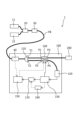
- FIG. 1 is a diagram illustrating a configuration of an optical power supply system according to an embodiment of the present disclosure.
- FIG. 2 is a diagram illustrating a configuration of an optical power supply system according to a modified example of the embodiment of the present disclosure.
- Fig. 1 is a diagram showing a configuration of an optical power supply system according to an embodiment of the present disclosure.
- the optical power supply system 1 includes a first light source 11, a second light source 12, a light source switching unit 20, an optical fiber FB, and an optical node device 100.
- the optical power supply system 1 may include a transmission unit 30.
- another device 200 may be connected to the rear stage of the optical node device 100.
- the first light source 11 and the second light source 12 output light (power supply light) for optical power supply in the optical node device 100.
- the power supply light includes at least either the light of the first light source or the light of the second light source.
- the first light source 11 and the second light source 12 are beam light sources such as lasers. Note that the wavelength of the light of the first light source 11 may be different from the wavelength of the light of the second light source 12.
- the light source switching unit 20 introduces the power supply light output from the first light source 11 or the second light source 12 into the optical fiber FB.
- the light source switching unit 20 may be connected to the first light source 11 and the second light source 12, and selectively use one of the light from the first light source 11 and the light from the second light source 12 as the power supply light.
- the light source switching unit 20 may be an optical switch.
- the optical power supply system 1 does not have to include the light source switching unit 20.
- an administrator who manages the optical power supply system 1 may select either the first light source 11 or the second light source 12 and connect the selected light source to the optical fiber FB.
- the transmitter 30 superimposes a control signal on the power supply light at one end of the optical fiber FB and outputs the signal.
- the transmitter 30 may be an optical media converter that converts a control signal received from an external device as an electrical signal into an optical signal, and outputs the optical signal superimposed on the power supply light.
- the optical fiber FB transmits power supply light that includes either the light of the first light source 11 or the light of the second light source 12.
- the optical fiber FB may transmit power supply light on which a control signal is superimposed.
- the optical node device 100 is provided at the other end of the optical fiber FB, and the power supply light transmitted through the optical fiber FB is input to the optical node device 100.
- the power supply light on which a control signal is superimposed may also be input to the optical node device 100.
- the optical node device 100 includes a branching unit 110, a photoelectric conversion unit 120, a power storage unit 130, an optical switch 140, and a control unit 150.
- the optical node device 100 may also include a receiving unit 40.
- the receiving unit 40 receives the control signal superimposed on the power supply light at the other end of the optical fiber FB.
- the receiving unit 40 may be an optical media converter that receives a portion of the power supply light, converts it into an electrical signal, and outputs the electrical signal as a control signal.
- the control signal may be transmitted to the control unit 150, which will be described later.
- the receiving unit 40 may be a photodiode.
- the branching unit 110 receives the power supply light transmitted through the optical fiber FB.
- the branching unit 110 outputs the light of the first light source 11, which is included in the power supply light, from a first terminal T1, and outputs the light of the second light source 12 from a second terminal T2.
- the branching unit 110 may branch the light of the first light source 11 and the light of the second light source 12 by wavelength branching.
- the branching unit 110 may be a WDM (Wavelength Division Multiplexing) optical coupler.
- the photoelectric conversion unit 120 receives the power supply light and converts it into electrical power.
- the photoelectric conversion unit 120 may be a photodiode.
- the power storage unit 130 stores the power output from the photoelectric conversion unit 120.
- the power storage unit 130 may be a capacitor, a battery, etc.
- the optical switch 140 has a first port P1, a second port P2, a third port P3, and a fourth port P4.
- the optical switch 140 has a first connection state in which the first port P1 and the third port P3, and the second port P2 and the fourth port P4 are connected.
- the optical switch 140 has a second connection state in which the first port P1 and the fourth port P4, and the second port P2 and the third port P3 are connected.
- the optical switch 140 is driven by power supplied from the power storage unit 130.
- the first port P1 of the optical switch 140 is connected to the first terminal T1 of the branching unit 110, and the second port P2 of the optical switch 140 is connected to the second terminal T2 of the branching unit 110.
- the fourth port P4 of the optical switch 140 is connected to the photoelectric conversion unit 120. Additionally, the third port P3 of the optical switch 140 may be connected to another device 200.
- the control unit 150 is driven by power supplied from the power storage unit 130, and controls at least the optical switch 140.
- the optical switch 140 switches between the first connection state and the second connection state based on a control signal from the control unit 150.
- the control signal may be a control signal received by the receiving unit 40.
- FIG. 2 is a diagram showing the configuration of an optical power supply system according to a modified example of the embodiment of the present disclosure. Unlike the optical node device 100 shown in Fig. 1, the optical node device 100 shown in Fig. 2 further includes a voltage monitoring unit 160 and a power supply control unit 170.
- the voltage monitoring unit 160 monitors the voltage of the power storage unit 130.
- the voltage monitoring unit 160 determines whether the voltage of the power storage unit 130 is equal to or greater than a predetermined threshold, and when it is equal to or greater than the predetermined threshold, it sends a signal to the power supply control unit 170.
- the power supply control unit 170 switches the control unit 150 between the on state and the off state based on a signal from the voltage monitoring unit 160. More specifically, when the power supply control unit 170 receives a signal from the voltage monitoring unit 160, it restarts the control unit 150. More specifically, the power supply control unit 170 switches the control unit 150 from the on state to the off state, and then switches the control unit 150 from the off state to the on state.
- the optical power supply system 1 may be in an abnormal state in the following cases.
- the power storage unit 130 of the optical node device 100 may be unable to supply power.
- the control unit 150 may be in an abnormal state.
- cases in which the power storage unit 130 of the optical node device 100 is unable to supply power include cases in which the power storage unit 130 loses power due to external disturbances such as erroneous control or lightning.
- Other examples include cases in which the optical node device 100 is left unused for a long period of time and the power stored in the power storage unit 130 is lost due to natural discharge, etc.
- Examples of cases in which the power storage unit 130 of the optical node device 100 is unable to supply power are not limited to the cases given here.
- control unit 150 is in an abnormal state is when the operation of the control unit 150 stops due to a disturbance such as erroneous control or a lightning strike.
- Examples of a case where the control unit 150 is in an abnormal state are not limited to the cases given here.
- the light from the second light source 12 is input to the optical fiber FB as power supply light.
- the light source switching unit 20 may be switched to input the light from the second light source 12 to the optical fiber FB, or an administrator may connect the second light source 12 and the optical fiber FB to input the light from the second light source 12 to the optical fiber FB.
- the light from the second light source 12 reaches the photoelectric conversion unit 120 via the optical fiber FB.
- the photoelectric conversion unit 120 converts the light from the second light source 12 that has reached it into electricity, and uses the converted electricity to charge the power storage unit 130.
- the light of the first light source 11 is input to the optical fiber FB as power supply light.
- the light source switching unit 20 may be switched to input the light of the first light source 11 to the optical fiber FB, or an administrator may connect the first light source 11 and the optical fiber FB to input the light of the first light source 11 to the optical fiber FB.
- the light of the first light source 11 reaches the photoelectric conversion unit 120 via the optical fiber FB.
- the photoelectric conversion unit 120 converts the light from the first light source 11 that has reached it into electricity, and uses the converted electricity to charge the storage unit 130.
- the control unit 150 when the control unit 150 is in an abnormal state and the optical switch 140 is in the first connection state, first, the light from the second light source 12 is input to the optical fiber FB as power supply light. As a result, the photoelectric conversion unit 120 converts the light from the second light source 12 that has arrived thereto into electricity, and the converted electricity is used to charge the storage unit 130.
- the control unit 150 when the control unit 150 is in an abnormal state and the optical switch 140 is in the second connection state, first, the light of the first light source 11 is input to the optical fiber FB as power supply light.
- the photoelectric conversion unit 120 converts the light of the first light source 11 that has arrived thereto into electricity, and the converted electricity is used to charge the storage unit 130.
- the voltage monitoring unit 160 sends a signal to the power supply control unit 170 indicating that the voltage of the power storage unit 130 has reached or exceeds the predetermined threshold. After that, when the power supply control unit 170 receives a signal from the voltage monitoring unit 160, it restarts the control unit 150.
- control unit 150 can be restarted to recover from the abnormal state.
- the optical power supply system of this embodiment includes a first light source, a second light source, an optical fiber that transmits power supply light including either light from the first light source or light from the second light source, and an optical node device to which the power supply light transmitted via the optical fiber is input.
- the optical node device includes a branching unit that receives power supply light, outputs light of a first light source from a first terminal, and outputs light of a second light source from a second terminal, a photoelectric conversion unit that receives the power supply light and converts it into electricity, a power storage unit that stores the power output from the photoelectric conversion unit, an optical switch having a first port, a second port, a third port, and a fourth port, and driven by power supplied from the power storage unit, and a control unit that controls at least the optical switch and is driven by power supplied from the power storage unit.
- the first terminal is connected to the first port
- the second terminal is connected to the second port
- the fourth port is connected to the photoelectric conversion unit.
- the optical switch has a first connection state in which the first port is connected to the third port and the second port is connected to the fourth port, and a second connection state in which the first port is connected to the fourth port and the second port is connected to the third port.
- the optical node device can be easily restored. In particular, recovery is possible from cases where power is lost in the power storage unit of the optical node device and the power storage unit is unable to supply power, or where the control unit of the optical node device is in an abnormal state.
- the wavelength of the light from the first light source may be different from the wavelength of the light from the second light source
- the branching section may branch the light from the first light source and the light from the second light source by wavelength branching. This allows at least either the light from the first light source or the light from the second light source to be reliably introduced into the photoelectric conversion section and the power storage section to be charged. As a result, the optical node device can be restored.
- the optical power supply system and optical node device may further include a light source switching unit that is connected to the first light source and the second light source and selectively switches either the light of the first light source or the light of the second light source to the power supply light. This allows at least either the light of the first light source or the light of the second light source to be introduced into an optical fiber and the power supply light to be guided to the optical node device.
- the optical node device can be restored by charging the power storage unit with the power supply light.
- the optical power supply system and optical node device may further include a transmitter at one end of the optical fiber that superimposes a control signal on the power supply light and outputs the superimposed control signal, and a receiver at the other end of the optical fiber that receives the control signal superimposed on the power supply light.
- the control unit may control at least the optical switch based on the control signal. This makes it possible to transmit a control signal for controlling the optical node device to the optical node device via the optical fiber when the control unit of the optical node device is not in an abnormal state.
- the optical power supply system and optical node device may further include a voltage monitoring unit that monitors the voltage of the power storage unit, and a power supply control unit that switches the control unit between the on state and the off state based on a signal from the voltage monitoring unit. This makes it possible to restart the control unit of the optical node device when the control unit is in an abnormal state.
- the recovery method of the optical power supply system may involve, when the optical switch is in the first connection state and the power storage unit cannot supply power to the control unit, inputting light from a second light source into the optical fiber as power supply light, causing the light from the second light source to reach the photoelectric conversion unit, and charging the power storage unit with the electricity converted from the light from the second light source.
- the optical node device can be easily restored. In particular, recovery is possible when power is lost in the power storage unit of the optical node device and the power storage unit is no longer able to supply power.
- the method for recovering the optical power supply system may involve, when the optical switch is in the first connection state and the control unit is in an abnormal state, inputting light from the second light source to the optical fiber as power supply light, causing the light from the second light source to reach the photoelectric conversion unit, and charging the power storage unit with the electricity converted from the light from the second light source. Then, the voltage monitoring unit may determine whether the voltage has reached or exceeded a predetermined threshold, and when it is determined that the voltage has reached or exceeded the predetermined threshold, the power supply control unit may restart the control unit to recover the control unit from the abnormal state.
- the optical node device can be easily restored.
- the optical node device can be restored from a state in which its control unit is in an abnormal state.
Landscapes
- Physics & Mathematics (AREA)
- Electromagnetism (AREA)
- Engineering & Computer Science (AREA)
- Computer Networks & Wireless Communication (AREA)
- Signal Processing (AREA)
- Optical Communication System (AREA)
Priority Applications (2)
| Application Number | Priority Date | Filing Date | Title |
|---|---|---|---|
| PCT/JP2023/003907 WO2024166191A1 (ja) | 2023-02-07 | 2023-02-07 | 光給電システム、光給電システムの復旧方法、及び、光ノード装置 |
| JP2024575897A JPWO2024166191A1 (https=) | 2023-02-07 | 2023-02-07 |
Applications Claiming Priority (1)
| Application Number | Priority Date | Filing Date | Title |
|---|---|---|---|
| PCT/JP2023/003907 WO2024166191A1 (ja) | 2023-02-07 | 2023-02-07 | 光給電システム、光給電システムの復旧方法、及び、光ノード装置 |
Publications (1)
| Publication Number | Publication Date |
|---|---|
| WO2024166191A1 true WO2024166191A1 (ja) | 2024-08-15 |
Family
ID=92262123
Family Applications (1)
| Application Number | Title | Priority Date | Filing Date |
|---|---|---|---|
| PCT/JP2023/003907 Ceased WO2024166191A1 (ja) | 2023-02-07 | 2023-02-07 | 光給電システム、光給電システムの復旧方法、及び、光ノード装置 |
Country Status (2)
| Country | Link |
|---|---|
| JP (1) | JPWO2024166191A1 (https=) |
| WO (1) | WO2024166191A1 (https=) |
Citations (4)
| Publication number | Priority date | Publication date | Assignee | Title |
|---|---|---|---|---|
| JP2008227904A (ja) * | 2007-03-13 | 2008-09-25 | Dx Antenna Co Ltd | 光端末装置付加用光電変換装置 |
| WO2011158283A1 (ja) * | 2010-06-14 | 2011-12-22 | 富士通テレコムネットワークス株式会社 | 光伝送システム |
| JP2015115657A (ja) * | 2013-12-09 | 2015-06-22 | 富士通テレコムネットワークス株式会社 | 光伝送システムおよび受信端局装置 |
| WO2021024809A1 (ja) * | 2019-08-06 | 2021-02-11 | 京セラ株式会社 | 光ファイバー給電システム |
-
2023
- 2023-02-07 WO PCT/JP2023/003907 patent/WO2024166191A1/ja not_active Ceased
- 2023-02-07 JP JP2024575897A patent/JPWO2024166191A1/ja active Pending
Patent Citations (4)
| Publication number | Priority date | Publication date | Assignee | Title |
|---|---|---|---|---|
| JP2008227904A (ja) * | 2007-03-13 | 2008-09-25 | Dx Antenna Co Ltd | 光端末装置付加用光電変換装置 |
| WO2011158283A1 (ja) * | 2010-06-14 | 2011-12-22 | 富士通テレコムネットワークス株式会社 | 光伝送システム |
| JP2015115657A (ja) * | 2013-12-09 | 2015-06-22 | 富士通テレコムネットワークス株式会社 | 光伝送システムおよび受信端局装置 |
| WO2021024809A1 (ja) * | 2019-08-06 | 2021-02-11 | 京セラ株式会社 | 光ファイバー給電システム |
Non-Patent Citations (1)
| Title |
|---|
| AKIHIRO KURODA, TOMOHIRO KAWANO, KAZUHIDE NAKAE, HIROSHI WATANABE, KAZUNORI KATAYAMA, TETSUYA MANABE: "B-13-16 A study on number of remote operated optical fiber switching nodes aligned in a line", LECTURE PROCEEDINGS OF THE 2022 GENERAL CONFERENCE OF IEICE: COMMUNICATION 2; SEPTEMBER 6-9, 2022, IEICE, JP, 23 August 2022 (2022-08-23) - 9 September 2022 (2022-09-09), JP, pages 160, XP009557374 * |
Also Published As
| Publication number | Publication date |
|---|---|
| JPWO2024166191A1 (https=) | 2024-08-15 |
Similar Documents
| Publication | Publication Date | Title |
|---|---|---|
| US6925219B2 (en) | Device for a passive optical network | |
| KR101100775B1 (ko) | 수동 광 네트워크에서의 결함들을 격리시키기 위한 안전 광 스플리터 및 방법 | |
| CN102934377B (zh) | 在海水下传输电力并提供光纤通信的系统和方法 | |
| CN101667865B (zh) | 波分复用无源光网络中实现保护倒换的装置、系统及方法 | |
| US20080166133A1 (en) | Optical network remote power supply system for remote switching unit | |
| US9722699B2 (en) | Systems and methods for managing power at an optical network terminal | |
| JP5070597B2 (ja) | 光伝送システム、光伝送方法、光スイッチ装置、センター装置、光カプラ装置、加入者装置及び光通信システム | |
| WO2024166191A1 (ja) | 光給電システム、光給電システムの復旧方法、及び、光ノード装置 | |
| JP7637388B2 (ja) | 光ファイバ経路切替装置及び方法 | |
| JP2015115657A (ja) | 光伝送システムおよび受信端局装置 | |
| JP2012257167A (ja) | 通信制御装置、終端装置及び通信制御システム | |
| JP2013074319A (ja) | 光伝送システム及び光中継装置 | |
| JP7653689B2 (ja) | 四方路光スイッチ及び光ファイバネットワーク | |
| JP7509213B2 (ja) | 光通信監視装置 | |
| CN115248482B (zh) | 一种光开关结构及光线路保护系统 | |
| KR100888945B1 (ko) | 링형 광전송망시스템 | |
| JP7447059B2 (ja) | ネットワーク装置およびネットワークシステム | |
| JP7782689B2 (ja) | 光通信システム、光ノード、及び光給電方法 | |
| WO2025134198A1 (ja) | 光ノードシステム、ノード、制御装置、切替方法およびプログラム | |
| CN103607238B (zh) | 光网络系统 | |
| CN101174901A (zh) | 光纤网络远端切换控制器电源供应装置 | |
| WO2024224473A1 (ja) | 光ノードシステム、ノードおよび遠隔再起動方法 | |
| JP6962441B2 (ja) | 海底ケーブルシステム、分岐装置及びその状態応答方法 | |
| KR101079135B1 (ko) | 수동형 광 가입자 망의 광선로 이중화 장치 및 그 방법 | |
| WO2024166300A1 (ja) | 光ノードシステム、給電制御方法、及びプログラム |
Legal Events
| Date | Code | Title | Description |
|---|---|---|---|
| 121 | Ep: the epo has been informed by wipo that ep was designated in this application |
Ref document number: 23921027 Country of ref document: EP Kind code of ref document: A1 |
|
| ENP | Entry into the national phase |
Ref document number: 2024575897 Country of ref document: JP Kind code of ref document: A |
|
| WWE | Wipo information: entry into national phase |
Ref document number: 2024575897 Country of ref document: JP |
|
| NENP | Non-entry into the national phase |
Ref country code: DE |
|
| 122 | Ep: pct application non-entry in european phase |
Ref document number: 23921027 Country of ref document: EP Kind code of ref document: A1 |