WO2024166300A1 - 光ノードシステム、給電制御方法、及びプログラム - Google Patents
光ノードシステム、給電制御方法、及びプログラム Download PDFInfo
- Publication number
- WO2024166300A1 WO2024166300A1 PCT/JP2023/004384 JP2023004384W WO2024166300A1 WO 2024166300 A1 WO2024166300 A1 WO 2024166300A1 JP 2023004384 W JP2023004384 W JP 2023004384W WO 2024166300 A1 WO2024166300 A1 WO 2024166300A1
- Authority
- WO
- WIPO (PCT)
- Prior art keywords
- node
- power storage
- child node
- power
- child
- Prior art date
- Legal status (The legal status is an assumption and is not a legal conclusion. Google has not performed a legal analysis and makes no representation as to the accuracy of the status listed.)
- Ceased
Links
Images


Classifications
-
- H—ELECTRICITY
- H04—ELECTRIC COMMUNICATION TECHNIQUE
- H04B—TRANSMISSION
- H04B10/00—Transmission systems employing electromagnetic waves other than radio-waves, e.g. infrared, visible or ultraviolet light, or employing corpuscular radiation, e.g. quantum communication
- H04B10/80—Optical aspects relating to the use of optical transmission for specific applications, not provided for in groups H04B10/03 - H04B10/70, e.g. optical power feeding or optical transmission through water
Definitions
- This disclosure relates to an optical node system, a power supply control method, and a program.
- optical line switching is performed at a certain frequency to connect optical fiber cores to optional routes or change routes in order to use the facilities efficiently during installation and maintenance. Normally, such work is performed by workers on-site to physically switch the connections, but a technology has been proposed that allows connections to be switched remotely using optical switches.
- Non-Patent Document 1 describes an optical node system in which multiple optical nodes (child nodes) are connected to a single optical fiber and these optical nodes are powered by optical fiber power supply.
- each optical node periodically measures the voltage of the capacitor that serves as the driving power source, and determines whether the optical fiber power supply should be directed to the node itself or to another node.
- the optical node uses a timer to measure the voltage measurement timing, which poses the problem of constant power consumption due to timer operation.
- This disclosure has been made in light of the above circumstances, and the purpose of this disclosure is to provide technology that reduces the power consumption of optical nodes.
- one aspect of the present disclosure is an optical node system having a parent node and multiple child nodes, the parent node having a light source that outputs light to the child node via an optical fiber, and a control device that controls the power supply to the child node, the control device instructs each child node to measure the voltage of a power storage unit at predetermined time intervals, determines the child node to be powered based on the voltage acquired from each child node, and transmits an instruction to the child node to switch the power supply destination to the determined child node, the child node having an optical switch that switches the light output from the parent node to its own node or another node, a power storage unit that stores electricity converted from the light, and a processing unit that measures the voltage of the power storage unit according to the voltage measurement instruction and transmits the measurement result to the parent node.
- One aspect of the present disclosure is a power supply control method performed by an optical node system having a parent node and multiple child nodes, in which the parent node outputs light to the child nodes via optical fiber, instructs each child node to measure the voltage of its power storage unit at predetermined time intervals, determines the child node to which power is to be supplied based on the voltage acquired from each child node, and transmits to the child node an instruction to switch the power supply destination to the determined child node to which power is to be supplied, the child node stores electricity converted from the light in a power storage unit, measures the voltage of the power storage unit in accordance with the instruction to measure the voltage, transmits the measurement result to the parent node, and switches the light output from the parent node to its own node or another node in accordance with the instruction to switch the power supply destination.
- One aspect of the present disclosure is a program for causing a computer to function as a control device for the optical node system.
- This disclosure provides technology that reduces the power consumption of optical nodes.
- FIG. 1 is a diagram showing the configuration of an optical node system according to the present embodiment.
- FIG. 2 is a flowchart showing an outline of the power supply control process performed by a parent node.
- FIG. 3 is a diagram illustrating an example of the power storage information.
- FIG. 4 is a diagram for explaining the levels of the charged state.
- FIG. 5 is a diagram illustrating an example of the power supply destination information.
- FIG. 6 is a flowchart showing the details of the voltage measurement instruction of FIG.
- FIG. 7 is a flowchart showing the details of the power supply destination determination in FIG.
- FIG. 8 is a flowchart showing the details of the power supply destination switching instruction in FIG.
- FIG. 9 is a diagram showing a hardware configuration.
- FIG. 1 shows the configuration of the optical node system of this embodiment.
- the optical node system of this embodiment comprises a parent node 1 and multiple child nodes 2A, 2B, and 2C.
- the upstream parent node 1 and the downstream child nodes 2A, 2B, and 2C are connected via an optical fiber 6 (optical fiber transmission path).
- optical fiber 6 optical fiber transmission path
- multiple child nodes 2A, 2B, and 2C are connected in series to one optical fiber 6.
- Child nodes 2A, 2B, and 2C may also be described as child nodes 2.
- Parent node 1 and child node 2 are also referred to as optical nodes.
- the parent node 1 is installed in an environment where power is available (for example, in a communications building), and supplies optical power (optical fiber power supply) to the child node 2 and communicates with the child node 2. Specifically, the parent node 1 outputs light for power supply to the child node 2 via optical fiber 6.
- the illustrated parent node 1 includes a control device 11 (controller), a light source 12 that outputs light to the child node 2, a signal generator 13, a light receiver 14, and an optical circulator 15. Note that light is also referred to as an optical signal in the following explanation.
- the optical circulator 15 splits the downstream optical signal (hereinafter, "downstream signal”) from the upstream optical signal (hereinafter, “upstream signal”).
- downstream signal and the upstream signal are split through the optical circulator 15, and a single optical fiber 6 can connect the parent node 1 and the child node 2.
- the light source 12 is composed of, for example, an internally modulated laser equipped with a modulation function, and is capable of superimposing a control signal to the child node 2 on the light for power supply.
- the laser light emitted from the light source 12 is input to the optical fiber 6 via the optical circulator 15.
- the wavelength of the laser light is, for example, 1480 nm to 1490 nm.
- the power of the laser light is, for example, about +10 to +17 dBm.
- the signal generating unit 13 generates a control signal as a downstream signal in response to an instruction from the control device 11, superimposes it on the light for power supply, and outputs it to the child node 2.
- the light receiving unit 14 receives the upstream signal output from the child node 2 via the optical fiber 6, converts it into an electrical signal, and outputs it to the control device 11.
- the upstream signal includes the voltage of the power storage units 29 and 31 measured by the child node 2.
- a light receiving element such as a photodiode is used for the light receiving unit 14.
- the illustrated control device 11 includes a control unit 111, a timer 112, a first memory unit 113, and a second memory unit 114.
- the control unit 111 controls the power supply to the child nodes 2. Specifically, the control unit 111 instructs each child node 2 to measure the voltage of the power storage units 29, 31 at predetermined time intervals, determines the child node 2 to be supplied with power based on the voltage acquired from each child node 2, and transmits an instruction to the corresponding child node 2 to switch the power supply destination to the determined child node 2 to be supplied with power. The control unit 111 may also determine which of the power storage units 29, 31 of the child node 2 to be supplied with power based on the voltage acquired from each child node 2.
- control unit 111 sends a modulated signal to the signal generation unit 13, and superimposes a control signal to the child node 2 on the light for power supply output by the light source 12.
- the control signal includes, for example, an instruction to measure the voltage of the power storage units 29 and 31, a switching instruction to switch the power storage unit 29 or 31 to which power is supplied, and the like.
- the control unit 111 uses the timer 112 to periodically execute the power supply control process (described later) at predetermined time intervals (predetermined time intervals) and communicates with the child node 2. Specifically, the control unit 111 stores the power storage state based on the voltage of the power storage units 29, 31 acquired from the child node 2 by the power supply control process in the power storage information of the first storage unit 113. The control unit 111 also determines the power storage unit 29, 31 to be the next power supply destination based on the power storage information, and stores the determined power supply destination in the power supply destination information of the second storage unit 114.
- the timer 112 measures the timing of measuring the voltage of the power storage units 29 and 31 of the child node 2. In other words, the timer 112 measures the timing of the power supply control process that is executed periodically.
- the first memory unit 113 stores power storage information
- the second memory unit 114 stores power supply destination information. The power storage information and power supply destination information will be described later.
- Child node 2 is connected to parent node 1 via optical fiber 6 and is a device capable of storing electricity through optical power supply. Therefore, child node 2 can be installed in a place without a power source.
- multiple child nodes 2 are connected in series to a parent node 1 via an optical fiber 6 and an optical switch 22. This allows the light source 12 of the parent node 1 to drive multiple child nodes 2.
- the illustrated child node 2A includes an optical coupler 21, an optical switch 22, an opto-electrical conversion unit 23, an optical circulator 24, an optical coupler 25, a light receiving unit 26, a signal generating unit 27, a microcomputer 28, power storage units 29 and 31, a load switch (LSW) 30, and a device 32.
- an optical coupler 21 an optical switch 22, an opto-electrical conversion unit 23, an optical circulator 24, an optical coupler 25, a light receiving unit 26, a signal generating unit 27, a microcomputer 28, power storage units 29 and 31, a load switch (LSW) 30, and a device 32.
- LSW load switch
- Optical coupler 21 splits the light output from parent node 1 into two.
- Optical coupler 21 is a multiplexer/demultiplexer that can multiplex/split downstream light and upstream light.
- Optical coupler 21 is a split ratio coupler that splits a larger optical power of the downstream light output from parent node 1 to optical switch 22 with a split ratio of, for example, 90:10. The light with the smaller optical power split by optical coupler 21 is guided to optical circulator 24.
- the optical switch 22 switches one of the lights branched from the optical coupler 21 to its own node or another node.
- the optical switch 22 can switch the optical power supply direction used for power storage between its own node and a lower node.
- the optical switch 22 is placed directly below the optical coupler 21, and switches whether the downstream light branched from the optical coupler 21 is guided to its own photoelectric conversion unit 23 or to the child node 2B installed downstream.
- the optical switch 22 can be, for example, a 2x2 optical switch.
- the photoelectric conversion unit 23 converts the light output from the optical switch 22 into electricity and stores it in the storage units 29, 31.
- the photoelectric conversion unit 23 uses a photoelectric conversion element capable of receiving the wavelength of the laser light emitted by the light source 12.
- the photoelectric conversion element is an easily available element suitable for the long wavelength band of 1300 nm to 1600 nm used for communications, such as an element made of indium gallium arsenide, with an open circuit voltage of 5 V or less and a conversion efficiency of approximately 30%.
- the wavelength of the light emitted by the light source 12 is a wavelength that corresponds to the photoelectric conversion element of the photoelectric conversion unit 23 used.
- the power storage unit 29 stores the electrical energy converted by the photoelectric conversion unit 23.
- an electric double layer capacitor can be used for the power storage unit 29.
- the electrical energy stored in the power storage unit 29 serves as a power source for the microcomputer 28, the optical switch 22, the signal generation unit 27, etc.
- the optical circulator 24 separates the other light branched off from the optical coupler 21 into a downstream signal and an upstream signal.
- Optical coupler 25 branches the light separated by optical circulator 24. Optical coupler 25 further branches the light branched by optical coupler 21 so that it can receive a control signal from parent node 1 regardless of the switching state of optical switch 22. The light branched by optical coupler 25 is guided to light receiving unit 62, which receives the light as a downstream signal, and signal generating unit 27, which generates an upstream signal. This makes it possible to receive a downstream signal for node 2A even if optical switch 22 is switched to node 2B, which is downstream of node 2A.
- the light receiving unit 26 receives one of the lights branched from the optical coupler 25 as a downstream signal.
- the light receiving unit 26 uses a light receiving element such as a photodiode.
- the signal generating unit 27 modulates the other light branched by the optical coupler 25 to generate modulated light, and outputs the modulated light to the parent node 1.
- the signal generating unit 27 includes a reflective optical switch (not shown) that performs modulation synchronized with a signal from the microcomputer 28, which will be described later.
- the signal generating unit 27 modulates the light branched by the optical coupler 25 with the optical switch to generate modulated light.
- the generated modulated light is output to the parent node 1 via the optical fiber 6 as an upstream signal to the parent node 1.
- the signal generating unit 27 may modulate the other light based on the voltage of the power storage units 29 and 31 to generate modulated light, and output the modulated light to the parent node 1.
- the signal generating unit 27 should operate at a low voltage and with low power consumption of a few ⁇ W or less.
- an electrostatically driven MEMS optical switch which has low drive power and is generally available.
- the microcomputer (processing unit) 28 controls active elements such as the optical switch 22, the signal generating unit 27, the load switch 30, and the device 32.
- the microcomputer 28 can be, for example, a microprocessor.
- the microcomputer 28 analyzes the downstream signal received by the light receiving unit 26.
- the light output by the light source 12 of the parent node 1 is intensity-modulated into the output laser light under the control of the control device 11, and becomes a downstream signal such as a TTL (Time to Live) or CMOS signal.
- the downstream signal includes various control signals such as measurement instructions for the power storage units 29 and 31 and instructions to switch the power supply destination.
- the microcomputer 28 generates an upstream signal by modulating the optical switch provided in the signal generating unit 27.
- the microcomputer 28 measures the voltages of the power storage units 29 and 31 using an AD converter (not shown) provided in the microcomputer 28. For example, the microcomputer 28 measures the voltages of the power storage units 29 and 31 in accordance with a control signal from the parent node 1, generates an upstream signal including the measured voltage using the signal generation unit 27, and transmits it to the parent node 1. The microcomputer 28 operates the optical switch 22 or the load switch 30 in accordance with the control signal from the parent node 1 to switch the power supply destination.
- AD converter not shown
- the load switch 30 is provided between the power storage unit 29 and the power storage unit 31, and controls the power supply from the power storage unit 29 to the power storage unit 31. Specifically, the load switch 30 performs on/off control so that power is supplied to the power storage unit 31 (device 32) only when necessary.
- the load switch 30 is driven according to instructions from the microcomputer 28. This makes it possible to reduce unnecessary consumption of the minute amount of power supplied to the child node 2A.
- the device 32 is driven by the power stored in the power storage unit 31.
- the device 32 is, for example, a specific device such as a sensor.
- Each part of the child node 2 is connected via a power storage distribution line 41 and/or a signal line 42.
- Child node 2B is connected in series to child node 2A via optical fiber 6.
- Child node 2C is connected in series to child node 2B via optical fiber 6.
- the configurations of child nodes 2B and 2C are the same as child node 2A.
- the number of child nodes 2 connected to the parent node 1 may be two, four, or more.
- another child node (not shown) may be connected downstream of child node 2C.
- the illustrated child node 2 has two power storage units 29 and 31, it may have only one power storage unit. In this case, the device 32 is driven using the power stored in the power storage unit 29.
- the child node 2 may have three or more power storage units.
- the child node located farthest from the parent node 1 may not have an optical switch 22, and may directly connect the optical coupler 21 and the photoelectric conversion unit 23.
- FIG. 2 is a flowchart showing an overview of the power supply control process performed by the control device 11 (control unit 111) of the parent node 1 in this embodiment.
- the control device 11 instructs the child node 2 to measure voltage using the power supply destination information stored in the second storage unit 114 (S1).
- the child node 2 measures the voltage of the power storage units 29, 31 included in the node itself in accordance with the instruction from the parent node 1, and transmits the measured voltage to the parent node 1.
- the parent node 1 stores the voltage state based on the voltage acquired from the child node 2 in the power storage information in the first storage unit 113.
- control device 11 uses the power storage information and the power supply destination information to determine the power storage unit 29, 31 of the child node 2 to which power should be supplied next, and updates the power supply destination information with the determined power supply destination (S3).
- control device 11 sequentially instructs the corresponding child nodes 2 to switch the power supply destination from the power storage unit 29, 31 currently supplying power to the power storage unit 29, 31 determined in S3 (S5).
- the control device 11 After completing the switching of S5, the control device 11 waits for a predetermined time (t seconds) (S7: NO). The control device 11 measures the predetermined time using the timer 112. After the predetermined time has elapsed (S7: YES), the control device 11 returns to S1 and repeats the subsequent processes. This allows the power supply control process shown in FIG. 2 to be executed periodically at predetermined time intervals.
- the child node 2 can measure the voltage of the power storage units 29 and 31 and change the frequency of transmitting the voltage to the parent node 1, thereby adjusting the power consumption of the child node 2.
- the control device 11 may extend the predetermined time (t seconds) or may stop the light source 12. Specifically, the control device 11 may multiply the predetermined time by t seconds x n to further reduce the communication frequency of the child nodes 2, or may stop the light source 12 for the predetermined time (t seconds). This allows the child nodes 2 to consume less power.
- a predetermined threshold upper threshold
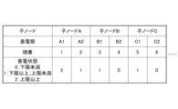
- FIG. 3 is an example of the power storage information stored in the first memory unit 113.
- the power storage information indicates the power storage state of the power storage units 29, 31 included in each child node 2.
- the control device 11 sets the power storage state of each power storage unit 29, 31 in the power storage information using the voltage of the power storage units 29, 31 acquired from the child node 2 and a first threshold value and a second threshold value.
- the second threshold value is a value greater than the first threshold value.
- the control device 11 classifies the power storage state of each power storage unit 29, 31 into levels based on the measured voltage, and stores the power storage units 29, 31 in association with the levels of the power storage state in the power storage information.
- the illustrated power storage information is written in order from the power storage units 29, 31 of the child node 2 closest to the parent node 1, and each power storage unit 29, 31 is numbered.
- the child nodes 2A, 2B, and 2C in FIG. 1 are written as "child node A,” “child node B,” and “node C,” respectively.
- the power storage unit 29 of child node 2A in FIG. 1 is labeled “A1,” and the power storage unit 31 is labeled "A2.”
- the power storage unit 29 of child node 2B in FIG. 1 is labeled "B2”
- the power storage unit 31 is labeled "B2.”
- the power storage unit 29 of child node 2C in FIG. 1 is labeled "C2”
- the power storage unit 31 is labeled "C2.”
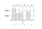
- FIG. 4 is a diagram for explaining the levels of the power storage state in FIG. 3.
- a first threshold lower limit voltage
- a second threshold upper limit voltage
- the control device 11 sets the levels by comparing the voltage of each power storage unit 29, 31 measured by the child node 2 with the first and second thresholds.
- a voltage level less than the first threshold is set to "0”
- a voltage level equal to or greater than the first threshold and less than the second threshold is set to "1”
- a voltage level equal to or greater than the second threshold is set to "2”.
- the voltages indicate the amount of power stored in the power storage units 29, 31.
- the initial values of the power storage state are all 0.
- FIG. 5 is an example of power supply destination information stored in the second memory unit 114.
- the power supply destination information is set with information about the power supply destination determined by the control device 11 based on the power storage information.
- the power supply destination information indicates the power storage units 29, 31 of the child node that are currently supplying power.
- the power supply destination information shown in the figure is set with the power supply status of each power storage unit 29, 31 of each child node 2.
- the power supply status is represented by "0" when no power is being supplied and "1" when power is being supplied.
- the power supply destination information shown is described in order starting from the power storage units 29, 31 of child node 2 closest to parent node 1, similar to the power storage information in FIG. 3, and each power storage unit 29, 31 is numbered.
- the initial value of the power supply destination information is "1" (power supplying) for A1 (power storage unit 29 of child node 2A), and "0" for all other power storage units 29, 31.
- "1" (power supplying) is not set to multiple power storage units 29, 31 at the same time.
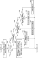
- FIG. 6 is a flowchart showing the details of the voltage measurement instruction (S1) in the flowchart of FIG. 2.
- the control device 11 refers to the power supply destination information in the second storage unit 114 to identify the power storage units 29, 31 that are the current power supply destinations. That is, the control device 11 identifies the power storage units 29, 31 whose power supply status is set to "1" (power supplying). The control device 11 then sets the order of the power storage units 29, 31 whose power supply status is set to "1" in the variable Y (S11).
- the control device 11 then sequentially issues voltage measurement instructions to each of the corresponding child nodes 2, numbered 1 to Y, to measure the voltage of each of the power storage units 29, 31, and acquires the voltage measurement results for numbers 1 to Y from each child node 2 (S12).
- the control device 11 instructs the child node 2 currently receiving power and the child nodes 2 disposed between the child node 2 and the parent node to measure the voltage of the power storage units 29, 31. This makes it possible to reduce the power consumption of child nodes 2 downstream of the child node 2 currently receiving power.
- control device 11 uses the two thresholds to set the acquired power storage state level of each power storage unit 29, 31 and updates the power storage information (S13 to S18). Note that the control device 11 performs the processes of S13 to S18 for each power storage unit 29, 31 for which it has instructed to perform measurement.
- control device 11 compares the measured voltage with a second threshold (upper limit voltage), and if the measured voltage is equal to or greater than the second threshold (S13: YES), it determines that the level of the power storage state is "2" (upper limit or greater), and sets the power storage state of the relevant power storage unit 29, 31 in the power storage information to "2" (S14).
- a second threshold upper limit voltage
- the control device 11 determines that the level of the power storage state is "0" (less than the lower limit) and sets the power storage state of the relevant power storage unit 29, 31 in the power storage information to "0" (S16).
- the control device 11 determines that the level of the power storage state is "1" (equal to or greater than the lower limit and less than the upper limit), and sets the power storage state of the power storage unit 29, 31 in the power storage information to "1" (S17).
- next power storage unit S18: YES
- the control device 11 returns to S13 and repeats the subsequent process for the next power storage unit 29, 31. If there is no next power storage unit 29, 31, that is, if the power storage states of power storage units 29, 31 from 1 to Y have been updated (S18: NO), the control device 11 ends the process.
- FIG. 7 is a flowchart showing the details of the power supply destination determination process (S3) in the flowchart of FIG. 2.
- the child node 2 has two power storage units 29 and 31.
- the priority of the power storage unit 29 is set higher than that of the power storage unit 31.
- the priority of the child nodes 2 increases in order of proximity to the parent node 1. In other words, power is supplied preferentially to the child nodes 2 closest to the parent node 1. This makes it possible to control the power supply to multiple child nodes 2 connected in series in sequence.
- the control device 11 determines the next power supply destination power storage unit 29, 31 based on the power storage information updated after the measurement instruction of the power storage units 29, 31 in S1 and the power supply destination information stored in the second storage unit 114, and updates the power supply destination information.
- the power supply destination information stored in the second storage unit 114 is the power supply destination information updated in the previous process t seconds ago, and indicates the power storage unit 29, 31 of the current power supply destination.
- control device 11 refers to the power storage information and, in descending order from the child node 2A that is located closest to the parent node 1, determines whether the power storage state of the power storage unit 29 with the highest priority is "0" (less than the first threshold value), and if a power storage unit 29 with a "0" state is detected, it determines that this power storage unit 29 is the power supply destination (S31).
- control device 11 checks the power storage state of the power storage units 29 with higher priority in descending order, starting from the child node 2A that is located closest to the parent node 1 (the order of A1, B1, C1 in Figure 3).
- the control device 11 sets the order of the power storage unit 29 whose power storage state is set to "0" to the variable X (S32).
- the order of the power storage units 29 is the order in which A1 is number 1 as shown in FIG. 3.
- the control device 11 determines whether the Yth power storage unit 29, 31 currently supplying power is a power storage unit 29 with a high priority (S35). For example, the control device 11 refers to the power supply destination information and determines whether the Yth power storage unit 29, 31 is any of A1, B1, and C1 shown in FIG. 5.
- the control device 11 refers to the power storage information to acquire the power storage state of the Yth power storage unit 29. If the power storage state of the Yth power storage unit 29 is "2" (above the upper limit) (S36: YES), the Yth power storage unit 29 stores power at or above the upper limit voltage. In this case, the control device 11 determines that the power storage unit 31 with a low priority of the child node 2 (i.e., the Y+1th power storage unit 31) is the next power supply destination.
- the control device 11 updates the power supply state of the Yth power storage unit 29 in the power supply destination information from “1" to “0” and updates the power supply state of the y+1th power storage unit 31 from “0" to “1” (S37).
- the power supply destination is not switched in order to set the power storage state of the Yth power storage unit 29 to "2" (upper limit or higher), and the control device 11 does not update the power supply destination information (S39).
- the control device 11 determines that the Y+1th power storage unit 29 is the next power supply destination. Then, in order to switch the power supply destination to the Y+1th power storage unit 28, the control device 11 updates the power supply state of the Yth power storage unit 31 in the power supply destination information from "1" to "0" and updates the power supply state of the Y+1th power storage unit 29 from "0" to "1” (S37).
- the Y+1th power storage unit 29 is the power storage unit 29 with a high priority of the child node 2 connected in the downstream direction of the child node 2 including the Yth power storage unit 31.
- the power supply destination is not switched in order to set the power storage state of the Yth power storage unit 31 to "2" (upper limit or higher), and the control device 11 does not update the power supply destination information (S39).
- FIG. 8 is a flowchart showing the details of the power supply destination switching instruction (S5) in the flowchart of FIG. 2.
- the control device 11 sequentially instructs the corresponding child node 2 to switch the power supply destination power storage units 29, 31 and the child node of the power supply destination.
- the control device 11 temporarily stores the power supply destination information before the update in the second storage unit 114.
- control device 11 uses the power supply destination information before the update to identify the child node 2 and power storage units 29, 31 currently being supplied with power.
- the control device 11 also uses the updated power supply destination information to acquire the child node 2 and power storage units 29, 31 of the next power supply destination (S51).
- S51 the order of the power storage units 29, 31 currently being supplied with power before the update and the order of the power storage units 29, 31 of the next power supply destination after the update are acquired (see Figure 5).
- the control device 11 determines whether the power supply destination is to be switched to a child node 2 in a downward direction (a direction away from the parent node 1) starting from the child node 2 of the power storage units 29, 31 currently supplying power (S52). For example, the control device 11 may determine whether the direction is downward using the arrangement of the child node 2 and the order of the power storage units 29, 31 in the power supply destination information.
- the control device 11 When switching the child node 2 of the power storage unit 29, 31 being powered as the starting point to a child node 2 in the downstream direction (S52: YES), the control device 11 switches the load switch 30 for the child node 2 being powered and for the intermediate child node 2 (hereinafter, intermediate child node 2) arranged between the child node 2 being powered and the child node 2 of the power destination so that the power destination in the child node 2 is the power storage unit 29 with the higher priority, and transmits a switching instruction (control signal) to switch the optical switch 22 to the other node in the downstream direction (S53). Note that the control device 11 may transmit a switching instruction to the child node 2 being powered and the intermediate child node 2 in the order of the downstream direction, starting from the child node 2 being powered.
- control device 11 transmits a switching instruction to the child node 2 of the power supply destination to switch the load switch 30 so that the power storage units 29, 31 specified in the updated power supply destination information become the power supply destination (S53). It is assumed that the optical switch 22 of the child node 2 of the power supply destination is switched to its own node side.
- the control device 11 When switching the child node 2 to be powered to an upstream child node 2 (S54: NO) rather than switching the downstream direction (S52: NO), the control device 11 transmits a switching instruction to the child node 2 being powered to switch the load switch 30 so that the power supply destination in the child node 2 becomes the power storage unit 29 with the higher priority.
- the control device 11 also transmits a switching instruction to the intermediate child node 2 to switch the load switch 30 so that the power supply destination in the child node 2 becomes the power storage unit 29 with the higher priority, and to switch the optical switch 22 to its own node side (S55).
- the control device 11 may transmit switching instructions to the child node 2 being powered and the intermediate child node 2 in the order of the upstream direction, starting from the child node 2 being powered.
- control device 11 transmits a switching instruction to the child node 2 to be powered, to switch the optical switch 22 to its own node side, and to switch the load switch 30 so that the power storage units 29, 31 specified in the updated power supply destination information become the power supply destination (S55).
- the control device 11 sends a switching instruction to the child node 2 to switch the load switch 31 so that the power supply destination becomes the power storage unit 31 (S57).
- the control device 11 sends a switching instruction to the child node 2 to switch the load switch 31 so that the power supply destination becomes the power storage unit 29 (S59).
- the control device 11 does not send a switching instruction (S60).
- the optical node system of the present embodiment described above includes a parent node 1 and multiple child nodes 2.
- the parent node 1 includes a light source 12 that outputs light to the child node 2 via an optical fiber 6, and a control device 11 that controls the power supply to the child node 2.
- the control device 11 instructs each child node 2 to measure the voltage of the power storage units 29 and 31 at predetermined time intervals, determines the child node 2 to be powered based on the voltage acquired from each child node 2, and transmits an instruction to the child node 2 to switch the power supply destination to the determined child node 2 to be powered.
- the child node 2 includes an optical switch 22 that switches the light output from the parent node 1 to its own node or another node, power storage units 29 and 31 that store electricity converted from light, and a microcomputer 28 that measures the voltage of the power storage units 29 and 31 according to the voltage measurement instruction and transmits the measurement result to the parent node 1.
- the control device 11 of the parent node 1 transmits an instruction to measure the power of the power storage units 29, 31 to the child node 2 at predetermined time intervals.
- the power supply control process of the control device 11 shown in FIG. 2 is performed periodically at predetermined time intervals, thereby reducing the power consumption of the child node 2.
- control device 11 determines the child node 2 to which power is to be supplied based on the voltage acquired from the child node 2, and therefore can determine the power storage unit 29, 31 to which power is to be supplied based on the power storage state of the power storage units 29, 31.
- the power storage unit 29, 31 with the lowest voltage can be determined as the power supply destination.
- control device 11 holds the power storage information, so it can grasp the power storage state of the child node 2. Therefore, if an abnormality occurs in the power storage state of the child node 2 (for example, if the voltage falls below the second threshold (lower limit voltage)), measures such as dispatching workers to the site and carrying out emergency construction work can be taken immediately, thereby improving communication quality.
- an abnormality occurs in the power storage state of the child node 2 (for example, if the voltage falls below the second threshold (lower limit voltage))
- measures such as dispatching workers to the site and carrying out emergency construction work can be taken immediately, thereby improving communication quality.
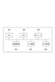
- the control device 11 described above can be, for example, a general-purpose computer system as shown in FIG. 9.
- the computer system shown in the figure comprises a CPU (Central Processing Unit, processor) 901, memory 902, storage 903 (HDD: Hard Disk Drive, SSD: Solid State Drive), communication device 904, input device 905, and output device 906.
- Memory 902 and storage 903 are storage devices.
- the functions of the control device 11 are realized by the CPU 901 executing a specific program loaded onto memory 902.
- the control device 11 may be implemented in one computer or in multiple computers.
- the control device 11 may also be a virtual machine implemented in a computer.
- the program of the control device 11 can be stored in a computer-readable recording medium such as a HDD, SSD, USB (Universal Serial Bus) memory, CD (Compact Disc), or DVD (Digital Versatile Disc), or can be distributed via a network.
- the computer-readable recording medium is, for example, a non-transitory recording medium.
- control device 11 is disposed within the parent node 1, but this is not limited to this.
- the control device 11 may be disposed independently outside the parent node 1. In this case, the control device 11 is connected to the signal generation unit 13 and the light receiving unit 14 of the parent node 1.
- Control device 111 Control unit 112: Timer 113: First memory unit 114: Second memory unit 12: Light source 13: Signal generation unit 14: Light receiving unit 15: Optical circulator 2, 2A, 2B, 2C: Child nodes 21, 25: Optical coupler 22: Optical switch 23: Photoelectric conversion unit 24: Optical circulator 26: Light receiving unit 27: Signal generation unit 28: Microcomputer (processing unit) 29, 31: Power storage unit 30: Load switch 32: Device
Landscapes
- Physics & Mathematics (AREA)
- Electromagnetism (AREA)
- Engineering & Computer Science (AREA)
- Computer Networks & Wireless Communication (AREA)
- Signal Processing (AREA)
- Optical Communication System (AREA)
Abstract
Description
11:制御装置
111:制御部
112:タイマ
113:第1記憶部
114:第2記憶部
12:光源
13:信号生成部
14:受光部
15:光サーキュレータ
2、2A、2B、2C:子ノード
21、25:光カプラ
22:光スイッチ
23:光電変換部
24:光サーキュレータ
26:受光部
27:信号生成部
28:マイコン(処理部)
29、31:蓄電部
30:ロードスイッチ
32:デバイス
Claims (8)
- 親ノードと複数の子ノードとを備える光ノードシステムであって、
前記親ノードは、
光ファイバを介して、前記子ノードに光を出力する光源と、
前記子ノードの給電を制御する制御装置と、を備え、
前記制御装置は、所定の時間毎に各子ノードに蓄電部の電圧測定を指示し、
各子ノードから取得した電圧に基づいて、給電先の子ノードを判定し、
判定した給電先の子ノードに給電先を切り替える指示を子ノードに送信し、
前記子ノードは、
前記親ノードから出力された光を自ノードまたは他ノードへ切り替える光スイッチと、
前記光から変換された電気を蓄電する蓄電部と、
前記電圧測定の指示に従って前記蓄電部の電圧を測定し、測定結果を前記親ノードに送信する処理部と、を備える
光ノードシステム。 - 前記子ノードは、複数の前記蓄電部を備え、
前記制御装置は、子ノードから取得した電圧に基づいて、給電先の子ノードのいずれかの蓄電部を判定する
請求項1に記載の光ノードシステム。 - 複数の前記子ノードは、前記親ノードに直列に接続され、
前記制御装置は、
各子ノードの蓄電部の蓄電状態を示す蓄電情報を記憶する第1記憶部を備え、
前記親ノードの最も近くに配置された子ノードから下り方向に順に、前記蓄電部の蓄電状態が所定の第1閾値以下の状態か否かを判定し、前記第1閾値未満の蓄電状態の蓄電部を検出した場合、当該蓄電部を給電先と判定する
請求項1に記載の光ノードシステム。 - 前記制御装置は、前記子ノードから取得した蓄電部の電圧と、前記第1閾値および前記第1閾値より大きな第2閾値とを用いて、前記蓄電情報における各蓄電部の蓄電状態を設定する
請求項3に記載の光ノードシステム。 - 前記制御装置は、複数の前記子ノードの蓄電部の電圧が全て所定の閾値以上の場合、前記所定の時間を長くする、または、前記光源を停止する
請求項1に記載の光ノードシステム。 - 複数の前記子ノードは、前記親ノードに直列に接続され、
前記制御装置は、
給電先の子ノードを、給電中の子ノードを起点として下り方向の子ノードに切り替える場合、前記給電中の子ノードの光スイッチと、前記給電中の子ノードと前記給電先の子ノードとの間に配置された子ノードの光スイッチとを、他ノード側に切り替える指示を送信し、
前記給電先の子ノードを、前記給電中の子ノードを起点として上り方向の子ノードに切り替える場合、前記給電中の子ノードと前記給電先の子ノードとの間に配置された子ノードの光スイッチを、自ノード側に切り替える指示を送信する
請求項1に記載の光ノードシステム。 - 親ノードと複数の子ノードとを備える光ノードシステムが行う給電制御方法であって、
前記親ノードは、
光ファイバを介して、前記子ノードに光を出力し、
所定の時間毎に各子ノードに蓄電部の電圧測定を指示し、
各子ノードから取得した電圧に基づいて、給電先の子ノードを判定し、
判定した給電先の子ノードに給電先を切り替える指示を子ノードに送信し、
前記子ノードは、
前記光から変換された電気を蓄電部に蓄電し、
前記電圧測定の指示に従って前記蓄電部の電圧を測定し、測定結果を前記親ノードに送信し、
前記給電先を切り替える指示に従って、前記親ノードから出力された光を自ノードまたは他ノードへ切り替える
給電制御方法。 - 請求項1に記載の前記光ノードシステムの制御装置として、コンピュータを機能させるためのプログラム。
Priority Applications (2)
| Application Number | Priority Date | Filing Date | Title |
|---|---|---|---|
| JP2024575994A JPWO2024166300A1 (ja) | 2023-02-09 | 2023-02-09 | |
| PCT/JP2023/004384 WO2024166300A1 (ja) | 2023-02-09 | 2023-02-09 | 光ノードシステム、給電制御方法、及びプログラム |
Applications Claiming Priority (1)
| Application Number | Priority Date | Filing Date | Title |
|---|---|---|---|
| PCT/JP2023/004384 WO2024166300A1 (ja) | 2023-02-09 | 2023-02-09 | 光ノードシステム、給電制御方法、及びプログラム |
Publications (1)
| Publication Number | Publication Date |
|---|---|
| WO2024166300A1 true WO2024166300A1 (ja) | 2024-08-15 |
Family
ID=92262176
Family Applications (1)
| Application Number | Title | Priority Date | Filing Date |
|---|---|---|---|
| PCT/JP2023/004384 Ceased WO2024166300A1 (ja) | 2023-02-09 | 2023-02-09 | 光ノードシステム、給電制御方法、及びプログラム |
Country Status (2)
| Country | Link |
|---|---|
| JP (1) | JPWO2024166300A1 (ja) |
| WO (1) | WO2024166300A1 (ja) |
Citations (4)
| Publication number | Priority date | Publication date | Assignee | Title |
|---|---|---|---|---|
| JP2006165651A (ja) * | 2004-12-02 | 2006-06-22 | Kansai Electric Power Co Inc:The | 光給電情報伝送装置 |
| JP2011196794A (ja) * | 2010-03-18 | 2011-10-06 | Central Res Inst Of Electric Power Ind | 多点型光センサシステム並びに多点型光センサシステムの制御方法及び制御プログラム |
| JP2019054423A (ja) * | 2017-09-15 | 2019-04-04 | 株式会社日立製作所 | 光給電システム |
| WO2022024270A1 (ja) * | 2020-07-29 | 2022-02-03 | 日本電信電話株式会社 | 光給電システム |
-
2023
- 2023-02-09 JP JP2024575994A patent/JPWO2024166300A1/ja active Pending
- 2023-02-09 WO PCT/JP2023/004384 patent/WO2024166300A1/ja not_active Ceased
Patent Citations (4)
| Publication number | Priority date | Publication date | Assignee | Title |
|---|---|---|---|---|
| JP2006165651A (ja) * | 2004-12-02 | 2006-06-22 | Kansai Electric Power Co Inc:The | 光給電情報伝送装置 |
| JP2011196794A (ja) * | 2010-03-18 | 2011-10-06 | Central Res Inst Of Electric Power Ind | 多点型光センサシステム並びに多点型光センサシステムの制御方法及び制御プログラム |
| JP2019054423A (ja) * | 2017-09-15 | 2019-04-04 | 株式会社日立製作所 | 光給電システム |
| WO2022024270A1 (ja) * | 2020-07-29 | 2022-02-03 | 日本電信電話株式会社 | 光給電システム |
Also Published As
| Publication number | Publication date |
|---|---|
| JPWO2024166300A1 (ja) | 2024-08-15 |
Similar Documents
| Publication | Publication Date | Title |
|---|---|---|
| JP7533623B2 (ja) | 監視制御装置及び光給電システム | |
| US6925219B2 (en) | Device for a passive optical network | |
| US9258629B2 (en) | System and method for an agile cloud radio access network | |
| US20140334811A1 (en) | Apparatus And Method For Conserving Power In A Passive Optical Network | |
| US20240236531A9 (en) | Communication system, transmitter, and communication method | |
| TWI584603B (zh) | Central office equipment and optical transmission system | |
| US9350447B1 (en) | Systems and methods for protecting optical networks from rogue optical network terminals | |
| WO2024166300A1 (ja) | 光ノードシステム、給電制御方法、及びプログラム | |
| JP2018157518A (ja) | 通信システム、光回線終端装置及び通信切替方法 | |
| JP2023031767A (ja) | 光ファイバ経路切替装置及び方法 | |
| JP7281361B2 (ja) | 光ファイバー給電システム | |
| JP7782689B2 (ja) | 光通信システム、光ノード、及び光給電方法 | |
| WO2024236699A1 (ja) | 光ノードシステム、コントローラ、給電制御方法及びプログラム | |
| JP7740541B2 (ja) | 光通信システム、光ノード、および光給電方法 | |
| JP7509213B2 (ja) | 光通信監視装置 | |
| WO2025134198A1 (ja) | 光ノードシステム、ノード、制御装置、切替方法およびプログラム | |
| KR101364101B1 (ko) | 광 신호 전송을 위한 기지국 시스템, 광 신호 전송을 위한 다중화 장치 | |
| WO2024224473A1 (ja) | 光ノードシステム、ノードおよび遠隔再起動方法 | |
| WO2024236639A1 (ja) | 光線路器、及び光ノード | |
| JP7626400B2 (ja) | 光ファイバ給電システム、光ファイバ給電方法及びノード装置 | |
| JP2024155563A (ja) | 光ネットワークシステム、及び遠隔装置 | |
| KR100275465B1 (ko) | 파장분할다중 광송신 장치 | |
| WO2024034062A1 (ja) | 端局装置、通信装置及び切替制御方法 | |
| US20250070868A1 (en) | Optical nodes, remote control systems, and remote control methods | |
| WO2024166191A1 (ja) | 光給電システム、光給電システムの復旧方法、及び、光ノード装置 |
Legal Events
| Date | Code | Title | Description |
|---|---|---|---|
| 121 | Ep: the epo has been informed by wipo that ep was designated in this application |
Ref document number: 23921131 Country of ref document: EP Kind code of ref document: A1 |
|
| ENP | Entry into the national phase |
Ref document number: 2024575994 Country of ref document: JP Kind code of ref document: A |
|
| WWE | Wipo information: entry into national phase |
Ref document number: 2024575994 Country of ref document: JP |
|
| NENP | Non-entry into the national phase |
Ref country code: DE |
|
| 122 | Ep: pct application non-entry in european phase |
Ref document number: 23921131 Country of ref document: EP Kind code of ref document: A1 |