WO2024162005A1 - ガラス板及びその製造方法 - Google Patents
ガラス板及びその製造方法 Download PDFInfo
- Publication number
- WO2024162005A1 WO2024162005A1 PCT/JP2024/001142 JP2024001142W WO2024162005A1 WO 2024162005 A1 WO2024162005 A1 WO 2024162005A1 JP 2024001142 W JP2024001142 W JP 2024001142W WO 2024162005 A1 WO2024162005 A1 WO 2024162005A1
- Authority
- WO
- WIPO (PCT)
- Prior art keywords
- main surface
- glass plate
- removal step
- glass
- mother
- Prior art date
- Legal status (The legal status is an assumption and is not a legal conclusion. Google has not performed a legal analysis and makes no representation as to the accuracy of the status listed.)
- Ceased
Links
Images





Classifications
-
- C—CHEMISTRY; METALLURGY
- C03—GLASS; MINERAL OR SLAG WOOL
- C03B—MANUFACTURE, SHAPING, OR SUPPLEMENTARY PROCESSES
- C03B33/00—Severing cooled glass
- C03B33/02—Cutting or splitting sheet glass or ribbons; Apparatus or machines therefor
-
- B—PERFORMING OPERATIONS; TRANSPORTING
- B24—GRINDING; POLISHING
- B24B—MACHINES, DEVICES, OR PROCESSES FOR GRINDING OR POLISHING; DRESSING OR CONDITIONING OF ABRADING SURFACES; FEEDING OF GRINDING, POLISHING, OR LAPPING AGENTS
- B24B7/00—Machines or devices designed for grinding plane surfaces on work, including polishing plane glass surfaces; Accessories therefor
- B24B7/20—Machines or devices designed for grinding plane surfaces on work, including polishing plane glass surfaces; Accessories therefor characterised by a special design with respect to properties of the material of non-metallic articles to be ground
- B24B7/22—Machines or devices designed for grinding plane surfaces on work, including polishing plane glass surfaces; Accessories therefor characterised by a special design with respect to properties of the material of non-metallic articles to be ground for grinding inorganic material, e.g. stone, ceramics, porcelain
- B24B7/24—Machines or devices designed for grinding plane surfaces on work, including polishing plane glass surfaces; Accessories therefor characterised by a special design with respect to properties of the material of non-metallic articles to be ground for grinding inorganic material, e.g. stone, ceramics, porcelain for grinding or polishing glass
- B24B7/242—Machines or devices designed for grinding plane surfaces on work, including polishing plane glass surfaces; Accessories therefor characterised by a special design with respect to properties of the material of non-metallic articles to be ground for grinding inorganic material, e.g. stone, ceramics, porcelain for grinding or polishing glass for plate glass
-
- C—CHEMISTRY; METALLURGY
- C03—GLASS; MINERAL OR SLAG WOOL
- C03B—MANUFACTURE, SHAPING, OR SUPPLEMENTARY PROCESSES
- C03B17/00—Forming molten glass by flowing-out, pushing-out, extruding or drawing downwardly or laterally from forming slits or by overflowing over lips
- C03B17/06—Forming glass sheets
-
- C—CHEMISTRY; METALLURGY
- C03—GLASS; MINERAL OR SLAG WOOL
- C03B—MANUFACTURE, SHAPING, OR SUPPLEMENTARY PROCESSES
- C03B17/00—Forming molten glass by flowing-out, pushing-out, extruding or drawing downwardly or laterally from forming slits or by overflowing over lips
- C03B17/06—Forming glass sheets
- C03B17/064—Forming glass sheets by the overflow downdraw fusion process; Isopipes therefor
-
- C—CHEMISTRY; METALLURGY
- C03—GLASS; MINERAL OR SLAG WOOL
- C03C—CHEMICAL COMPOSITION OF GLASSES, GLAZES OR VITREOUS ENAMELS; SURFACE TREATMENT OF GLASS; SURFACE TREATMENT OF FIBRES OR FILAMENTS MADE FROM GLASS, MINERALS OR SLAGS; JOINING GLASS TO GLASS OR OTHER MATERIALS
- C03C15/00—Surface treatment of glass, not in the form of fibres or filaments, by etching
Definitions
- the present invention relates to a glass plate and a method for manufacturing the same.
- glass plates are used in a variety of fields, including substrates and cover glass for displays such as liquid crystal displays and organic electroluminescence displays, and chemically strengthenable cover glass used in mobile devices such as smartphones, tablets, and notebook PCs, particularly foldable devices.
- substrates and cover glass for displays such as liquid crystal displays and organic electroluminescence displays
- chemically strengthenable cover glass used in mobile devices such as smartphones, tablets, and notebook PCs, particularly foldable devices.
- Well-known methods such as the overflow downdraw method are used to manufacture this type of glass plate.
- the overflow downdraw method involves pouring molten glass into an overflow groove provided at the top of a forming body with a roughly wedge-shaped cross section, allowing the molten glass to overflow on both sides of the overflow groove to flow down along both sidewall surfaces of the forming body, and then fusing and integrating the glass at the bottom end of the forming body to continuously form a glass ribbon (see, for example, Patent Document 1).
- the glass ribbon After the glass ribbon has undergone a specified cooling process, its middle portion is cut widthwise. This allows individual glass sheets to be cut out from the glass ribbon.
- the forming body used in the overflow downdraw method is composed of alumina-based, zirconia-based, or other refractory materials.
- components contained in the forming body e.g. Al, Zr, etc.
- the molten glass fuses at the lower end of the forming body, the components originating from the forming body remain on the mating surface of the glass ribbon formed by this fusion.
- the present invention was made in consideration of the above circumstances, and its technical objective is to efficiently remove the mating surfaces of glass sheets produced by overflow molding.
- the present invention is intended to solve the above problems, and is a method for manufacturing a glass plate, comprising a forming step of forming a glass ribbon from molten glass using a forming body that performs overflow forming, a cutting step of cutting a mother glass plate from the glass ribbon, and a processing step of manufacturing a glass plate by performing a predetermined processing on the mother glass plate, wherein the forming body has a pair of side wall surfaces through which the molten glass flows down, and a lower end portion that fuses the molten glass flowing down the pair of side wall surfaces, and the thickness of the mother glass plate is 150 ⁇ m or more and 1300 ⁇ m or less.
- the mother glass plate has a first main surface, a second main surface, an end surface connecting the first main surface and the second main surface, and a mating surface formed by fusing the molten glass at the lower end of the molded body
- the processing step includes a first removal step of removing the first main surface of the mother glass plate, and the first removal step removes the first main surface of the mother glass plate so that the distance between the mating surface and the center position of the first main surface and the second main surface in the plate thickness direction of the mother glass plate is larger than before the first removal step.
- the first main surface of the mother glass plate is removed in the first removal step so that the distance between the mating surface and the center position of the glass plate is increased, and the mating surface is positioned biased toward the first main surface.
- the mating surface is positioned biased toward the first main surface.
- an etching process may be performed on the first main surface of the mother glass plate. This allows the mother glass plate to be processed with high precision.
- a groove extending parallel to the second main surface may be formed in the end surface of the mother glass plate at a position corresponding to the joining surface.
- the first main surface of the mother glass plate in the first removal step, may be subjected to mechanical polishing or chemical mechanical polishing. This allows the first main surface to be processed efficiently and accurately.
- the distance between the joining surface of the mother glass plate and the center position of the first main surface and the second main surface of the mother glass plate before the first removal step may be less than 10 ⁇ m.
- the thickness of the molten glass flowing down from one side wall surface of the molding body may differ slightly from that of the molten glass flowing down from the other side wall surface.
- the mating surface of the mother glass plate is formed at a position away from the center position in the plate thickness direction of the glass plate. If the distance between the position of the mating surface and the center position of the mother glass plate is large, warping and distortion of the mother glass plate may worsen. In this method, the distance between the position of the mating surface and the center position of the mother glass plate is less than 10 ⁇ m, thereby reducing warping and distortion of the mother glass plate as much as possible.
- the distance between the mating surface of the mother glass plate and the center positions of the first main surface and the second main surface of the mother glass plate before the first removal step is less than 10 ⁇ m" also includes the case where the mating surface and the center position coincide with each other before the first removal step.
- the distance between the joining surface of the mother glass plate and the center position of the first main surface and the second main surface of the mother glass plate after the first removal step may be 15 ⁇ m or more.
- the distance between the mating surface of the mother glass plate and the center position of the mother glass plate after the first removal step is set to 15 ⁇ m or more, and then, for example, the first and second main surfaces of the mother glass plate are simultaneously subjected to an etching process, thereby making it possible to efficiently remove the mating surface from the mother glass plate.
- the processing step may include a protection step of attaching a protection film to the second main surface of the mother glass plate before the first removal step, and a peeling step of peeling off the protection film from the second main surface after the first removal step.
- the second main surface can be protected by the protective film in the first removal step. Furthermore, by peeling the protective film from the second main surface of the mother glass plate in the peeling step, the mating surfaces can be efficiently removed by subsequently performing an etching process on the first and second main surfaces of the mother glass plate, for example.
- the treatment step may further include a second removal step in which an etching process is performed on the first main surface and the second main surface of the mother glass plate after the first removal step.
- the mating surface can be efficiently removed from the mother glass plate by performing the second removal process after the first removal process.
- a thickness of the glass plate after the second removal step is 10 ⁇ m or more and 120 ⁇ m or less
- a thickness of the mother glass plate before the first removal step is t 0 ( ⁇ m)
- a distance between the joining surface of the mother glass plate before the first removal step and the central position of the first main surface and the second main surface is d 1 ( ⁇ m)
- a thickness of the mother glass plate after the second removal step is t 2 ( ⁇ m)
- a removal amount ⁇ 1 ( ⁇ m) in the first removal step and a removal amount ⁇ 2 ( ⁇ m) in the second removal step can satisfy formulas (1) and (2).
- t 0 t 2 + ⁇ 1 +2 ⁇ 2 ...(1) (t 0 /2) + d 1 ⁇ ⁇ 1 + ⁇ 2 ...(2)
- This configuration allows the mating surface to be reliably removed from the mother glass plate.
- the present invention is directed to solving the above problems, and is a glass plate having a thickness of 90 ⁇ m or more and 680 ⁇ m or less, comprising a first main surface which is a removal processing surface, a second main surface which is a fire polished surface, an end surface connecting the first main surface and the second main surface, and a mating surface formed by the fusion of molten glass between the first main surface and the second main surface, the mating surface being 15 ⁇ m or more away from the center position between the first main surface and the second main surface toward the first main surface in the plate thickness direction.
- the mating surface is at least 15 ⁇ m away from the center position between the first and second principal surfaces toward the first principal surface, making it possible to efficiently remove the mating surface from the mother glass plate.
- the present invention is directed to solving the above problems, and is characterized in that it is a glass plate having a thickness of 90 ⁇ m or more and 680 ⁇ m or less, comprising a first main surface which is a removal processing surface, a second main surface which is a fire polished surface, an end surface connecting the first main surface and the second main surface, and a mating surface formed by the fusion of molten glass between the first main surface and the second main surface, the end surface having a groove portion extending parallel to the first main surface at a position corresponding to the mating surface, and the groove portion is 15 ⁇ m or more away from the center position between the first main surface and the second main surface toward the first main surface in the plate thickness direction.
- a groove corresponding to the position of the mating surface is formed on the edge surface of the glass plate, and the position of the groove is spaced 15 ⁇ m or more toward the first main surface from the center position between the first and second main surfaces, making it possible to efficiently remove the mating surface from the mother glass plate.
- FIG. 2 is a cross-sectional view showing a glass sheet manufacturing apparatus.
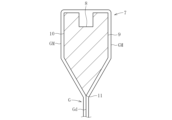
- FIG. 2 is a cross-sectional view showing a molded body.
- 1 is a flowchart showing a method for manufacturing a glass plate.
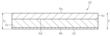
- FIG. 11 is a cross-sectional view showing a protection step in the processing steps.
- FIG. 2 is a cross-sectional view showing a first removal step in the processing process.
- FIG. 4 is a cross-sectional view showing the glass plate after a peeling step in the processing step.
- FIG. 2 is a cross-sectional view showing the glass sheet after a second removal step in the processing process.
- FIG. 2 is a comparison of a glass plate before and after a processing step.
- FIG. 2 is a comparison of a glass plate before and after a processing step.
- Figures 1 to 10A and 10B show one embodiment of a method for manufacturing a glass plate according to the present invention.
- FIG. 1 shows a glass sheet manufacturing apparatus used in this method.
- the manufacturing apparatus includes a forming device 1 that continuously forms a glass ribbon GR from molten glass GM, and a cutting device 2 that cuts out a mother glass sheet (hereinafter referred to as the "first glass sheet") G1 from the glass ribbon GR.
- a forming device 1 that continuously forms a glass ribbon GR from molten glass GM
- a cutting device 2 that cuts out a mother glass sheet (hereinafter referred to as the "first glass sheet") G1 from the glass ribbon GR.
- the forming device 1 includes a forming furnace 3 for forming the glass ribbon GR, an annealing furnace 4 for annealing the glass ribbon GR to reduce internal distortion of the glass ribbon GR, a cooling zone 5 for cooling the glass ribbon GR to near room temperature, and roller pairs 6 provided in multiple stages above and below each of the forming furnace 3, the annealing furnace 4, and the cooling zone 5.
- the roller pairs 6 hold both ends of the glass ribbon GR in the width direction, and convey and lower the glass ribbon GR while applying an appropriate tension to the glass ribbon GR.
- a forming body 7 is arranged, which forms the glass ribbon GR from the molten glass GM by the overflow downdraw method.
- the forming body 7 is made of, for example, alumina-based or zirconia-based refractory bricks, but the material of the forming body 7 is not limited to this embodiment.
- the forming body 7 has an overflow groove 8 at its upper part for overflowing the molten glass GM.
- the forming body 7 has a pair of side wall surfaces 9, 10 through which the molten glass GM flows down, and a lower end portion 11 that fuses the molten glass GM flowing down the pair of side wall surfaces 9, 10.
- the widthwise ends of the glass ribbon GR formed by the forming device 1 include ears (unnecessary parts) that are thicker than the widthwise center due to the effects of shrinkage during the forming process.
- the cutting device 2 cuts the glass ribbon GR in a vertical position below the forming device 1 in the width direction at predetermined lengths, thereby sequentially cutting out first glass sheets G1 from the glass ribbon GR.
- the cutting device 2 includes a scribing device (not shown) that forms a scribe line SL1 along the width direction on one surface of the glass ribbon GR, a contact portion 12 that supports the other surface of the glass ribbon GR at a position corresponding to the scribe line SL1, and a stress applying portion 13 that holds the portion of the glass ribbon GR that corresponds to the first glass sheet G1 to be cut out (the portion below the scribe line SL1) and applies a bending stress to the scribe line SL1.
- the scribing device includes, for example, a wheel cutter.
- the scribing device is not limited to a wheel cutter, and may be one that forms the scribe line SL1 using other methods, such as laser irradiation.
- the contact portion 12 is composed of a plate-like body (plate) having a contact surface that contacts the surface of the glass ribbon GR along the width direction of the glass ribbon GR while following the glass ribbon GR as it descends.
- the stress applying portion 13 has gripping portions (e.g., chucks) that grip both ends of the glass ribbon GR in the width direction.
- this method includes a forming process S1, an annealing process S2, a cooling process S3, a cutting process S4, and a processing process S5.
- the forming device 1 continuously forms the glass ribbon GR from the molten glass GM.
- the forming body 7 causes the molten glass GM to overflow from the overflow groove 8 and flow down along the side wall surfaces 9, 10 on both sides of the forming body 7.
- the molding body 7 fuses (converges) the molten glass GM that has flowed down at the lower end 11. This forms a glass ribbon GR having a predetermined width.
- the molten glass GM flowing down one side wall surface 9 of the molding body 7 fuses with the molten glass GM flowing down the other side wall surface 10 of the molding body 7, and the fused portion remains inside the glass ribbon GR as a layered mating surface Gd.
- the glass ribbon GR is transported downward by a pair of rollers 6 arranged in the annealing furnace 4.
- a predetermined temperature gradient is set in the annealing furnace 4, and the glass ribbon GR is annealed by passing through the annealing furnace 4.
- the glass ribbon GR is cooled to near room temperature while passing through a cooling zone 5 arranged below the annealing furnace 4.
- the cutting process S4 includes a first cutting process and a second cutting process.
- the cutting device 2 cuts the middle part of the glass ribbon GR along the width direction to cut out a first glass sheet G1 of a predetermined size. That is, in the first cutting process, a scribe line SL1 along the width direction is formed by a scribing device in the middle part of the glass ribbon GR moving downward (scribing process), and a part of the glass ribbon GR is bent and split along this scribe line SL1 to form a sheet-like first glass sheet G1 (bending and splitting process).
- the wheel cutter of the scribing device descends to follow the descending glass ribbon GR, forming a scribe line SL1 in the width direction of the glass ribbon GR.
- the stress applying unit 13 descends to follow the descending glass ribbon GR, performing an operation for bending the glass ribbon GR with the contact unit 12 as a fulcrum. This operation of the stress applying unit 13 applies a bending stress to the scribe line SL1.
- the glass ribbon GR is folded and broken in the width direction along the scribe line SL1, and a first glass sheet G1 is cut out from the glass ribbon GR.
- the end portion (unnecessary portion) in the width direction of the first glass plate G1 is cut and removed using a cutting device (not shown).
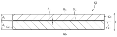
- the first glass sheet G1 has a first main surface Ga, a second main surface Gb, an end surface Gc connecting the first main surface Ga and the second main surface Gb, and a mating surface Gd.
- the upper limit of the sheet thickness t 0 of the first glass sheet G1 is preferably 1300 ⁇ m or less, more preferably 700 ⁇ m or less, and even more preferably 500 ⁇ m or less.
- the lower limit of the sheet thickness t 0 of the first glass sheet G1 is preferably 150 ⁇ m or more, more preferably 200 ⁇ m or more, and even more preferably 250 ⁇ m or more.
- the first principal surface Ga and the second principal surface Gb of the first glass sheet G1 are formed as fire-polished surfaces by the above-mentioned overflow downdraw method.
- the "fire-polished surface” refers to a surface that is formed without contacting the forming body 7 of the forming device 1. Such a fire-polished surface has excellent surface properties despite being unpolished.
- the dashed dotted line indicates the center line passing through the center position O1 in the thickness direction T of the first glass sheet G1, that is, the intermediate position between the first principal surface Ga and the second principal surface Gb.
- the distance from the center position O1 to the first principal surface Ga is equal to the distance from the center position O1 to the second principal surface Gb.
- the mating surface Gd of the first glass sheet G1 is formed when the glass ribbon GR is formed. As shown in FIG. 4, the mating surface Gd is located away from the center position O1 of the first glass sheet G1. The positional deviation between the mating surface Gd and the center position O1 is caused by the difference between the thickness of the molten glass GM flowing on one side wall surface 9 of the formed body 7 and the thickness of the molten glass GM flowing on the other side wall surface 10 in the forming step S1.
- the distance d 1 between the mating surface Gd of the first glass sheet G1 and the center position O1 of the first glass sheet G1 is preferably less than 10 ⁇ m, more preferably less than 5 ⁇ m.
- the distance d 2 in the thickness direction T from the mating surface Gd to the first main surface Ga is smaller than the distance d 3 in the thickness direction T from the mating surface Gd to the second main surface Gb (d 2 ⁇ d 3 ).
- the processing step S5 includes a protection step S51, a first removal step S52, a peeling step S53, and a second removal step S54.
- a protective film 14 is attached to the second main surface Gb of the first glass plate G1 before the first removal step S52 is performed.
- a resin film such as a polyethylene film, a polypropylene film, a polyimide film, or an acrylic film is used.
- the first main surface Ga of the first glass plate G1 is removed so as to increase the distance d 1 between the mating surface Gd and the center position O1 of the first main surface Ga and the second main surface Gb in the plate thickness direction T.
- the first main surface Ga is removed so as to decrease the distance d 2 between the first main surface Ga of the first glass plate G1 and the mating surface Gd.
- a polishing process is performed as a method for removing the first principal surface Ga of the first glass plate G1.
- the polishing process include mechanical polishing, chemical mechanical polishing, and chemical polishing.
- an example is shown in which the first principal surface Ga of the first glass plate G1 is removed by chemical polishing (etching).
- the first removal step S52 for example, a wet etching process is performed on the first main surface Ga of the first glass sheet G1.
- the first glass sheet G1 is immersed in an etching solution contained in an etching tank, for example.
- the etching solution used is, for example, an acidic aqueous solution containing hydrofluoric acid, hydrochloric acid, etc.
- This etching process removes the first main surface Ga and the end surface Gc of the first glass sheet G1 at a predetermined etching rate.
- the second main surface Gb of the first glass sheet G1 is protected by the protective film 14, so no etching process is performed. Therefore, the second main surface Gb maintains the state of a fire-polished surface even when the first removal step S52 is performed.
- FIG. 7 shows the mother glass plate (hereinafter referred to as the "second glass plate") G2 after the first removal step S52 has been performed.
- the second glass plate G2 has a first main surface Ga as a newly formed removal surface (polished surface) by the first removal step S52, a second main surface Gb as a fire polished surface, an end surface Gc newly formed by the first removal step S52, and a mating surface Gd.
- the first removal step S52 forms a groove Ge extending parallel to the first principal surface Ga and the second principal surface Gb at a position on the edge surface Gc of the second glass sheet G2 corresponding to the mating surface Gd.
- the mating surface Gd contains a component (e.g. Zr) derived from the formed body 7 mixed into the molten glass GM in the forming step S1.
- the etching rate differs between the portion on the edge surface Gc of the first glass sheet G1 where the mating surface Gd is formed and the other portions.
- the groove Ge is formed in a part of the edge surface Gc of the first glass sheet G1 (second glass sheet G2) in accordance with this difference in etching rate.
- the first removal step S52 forms an inclined surface Gf that is inclined with respect to the second main surface Gb at the boundary between the second main surface Gb and the edge surface Gc of the second glass plate G2.
- the inclined surface Gf is formed by the infiltration of an etching solution between the protective film 14 and the second main surface Gb of the first glass plate G1 in the first removal step S52.
- the sheet thickness t1 of the second glass sheet G2 is smaller than the sheet thickness t0 of the first glass sheet G1.
- the upper limit value of the sheet thickness t1 of the second glass sheet G2 is preferably 680 ⁇ m or less, more preferably 400 ⁇ m or less.
- the lower limit value of the sheet thickness t1 of the second glass sheet G2 is preferably 90 ⁇ m or more, more preferably 150 ⁇ m or more.
- the groove Ge is preferably 15 ⁇ m or more away from the center position O1 of the second glass sheet G2 toward the first main surface Ga in the sheet thickness direction T.
- the distance between the groove Ge and the center position O1 of the second glass sheet G2 is equal to the distance d 1 between the joining surface Gd of the second glass sheet G2 and the center position O1 of the second glass sheet G2 after the first removal step S52.
- This distance d 1 is larger than that before the first removal step S52.
- the upper limit of the distance d 1 is preferably 300 ⁇ m or less, more preferably 200 ⁇ m or less.
- the lower limit of the distance d 1 is preferably 15 ⁇ m or more, more preferably 30 ⁇ m or more.
- the distance d2 between the mating surface Gd and the first principal surface Ga in the sheet thickness direction T is smaller than the distance d2 before the first removal step S52.
- the distance d3 between the mating surface Gd and the second principal surface Gb in the sheet thickness direction T is equal to the distance d3 before the first removal step S52.
- the protective film 14 is peeled off from the second main surface Gb of the second glass plate G2.
- the protective film 14 may be pulled off from the second main surface Gb of the second glass plate G2, or the protective film 14 may be removed with an organic solvent.
- the second glass plate G2 may be cut into small glass plates, and each glass plate may be subjected to the etching process.
- the inclined surface Gf and the groove portion Ge may be cut out from the second glass plate G2.
- the second glass sheet G2 is immersed in an etching solution in an etching tank, and the first main surface Ga, the second main surface Gb, and the edge surface Gc are removed at the same etching rate. This removes the mating surface Gd from the second glass sheet G2.
- FIG. 9 shows a glass plate (hereinafter referred to as "third glass plate") G3 after the second removal step S54.
- the third glass plate G3 has a first main surface Ga, a second main surface Gb, and an end surface Gc newly formed by the second removal step S54.
- the plate thickness t2 of the third glass plate G3 is smaller than the plate thickness t1 of the second glass plate G2.
- the upper limit of the plate thickness t2 of the third glass plate G3 is preferably 120 ⁇ m or less, more preferably 90 ⁇ m or less.
- the lower limit of the plate thickness t2 of the third glass plate G3 is preferably 10 ⁇ m or more, more preferably 25 ⁇ m or more.
- This third glass plate G3 is used, for example, as glass substrates for devices such as panel displays, such as liquid crystal displays, plasma displays, and organic electroluminescence displays; solar cells, lithium ion batteries, digital signage, touch panels, and electronic paper; or as chemically strengthenable cover glass used in mobile devices, such as smartphones, tablets, and notebook PCs, particularly foldable devices; or as cover glass used in bendable thin-film solar cells and organic electroluminescence lighting; or as glass containers for medical products, window panes, lightweight laminated window glass, and glass for digital signage or glass resin laminates used as protective substrates for protective glasses, etc., but is not limited to these uses.
- panel displays such as liquid crystal displays, plasma displays, and organic electroluminescence displays
- solar cells lithium ion batteries
- digital signage digital signage
- touch panels and electronic paper
- chemically strengthenable cover glass used in mobile devices such as smartphones, tablets, and notebook PCs, particularly foldable devices
- cover glass used in bendable thin-film solar cells and organic electroluminescence lighting or as glass containers for medical products
- the third glass plate G3 may be, for example, an alkali aluminosilicate glass, and may contain, in mass %, 50 to 80% SiO 2 , 5 to 25% Al 2 O 3 , 0 to 15% B 2 O 3 , 1 to 20% Na 2 O , and 0 to 10% K 2 O. In addition, in the case of this composition, it is preferable that the glass does not substantially contain Li 2 O.
- the third glass plate G3 may have a glass composition containing, in mass %, 40% to 70% SiO2 , 10 % to 30% Al2O3 , 0% to 3% B2O3, 5 % to 25% Na2O, 0% to 5.5% K2O, 0.1% to 10% Li2O , 0% to 5.5% MgO, and 2 % to 10% P2O5 .
- This third glass plate G3 may be subjected to a chemical strengthening treatment (strengthening step) after the second removal step S54.
- the chemical strengthening treatment may involve one stage of ion exchange, or two stages or three or more stages of ion exchange.
- Fig. 10A shows an example of a first glass sheet G1 in which the mating surface Gd is away from the center position O1 toward the first main surface Ga
- Fig. 10B shows an example of a first glass sheet G1 in which the mating surface Gd is away from the center position O1 toward the second main surface Gb
- Fig. 10B shows an example of a first glass sheet G1 in which the mating surface Gd is away from the center position O1 toward the second main surface Gb
- Fig. 10B shows an example of a first glass sheet G1 in which the mating surface Gd is away from the center position O1 toward the first main surface Ga
- Fig. 10A shows an example of a first glass sheet G1 in which the mating surface Gd is away from the center position O1 toward the first main surface Ga
- Fig. 10B shows an example of a first glass sheet G1 in which the mating surface Gd is away from the center position O1 toward the second main surface Gb
- FIG. 10B shows an example of a first glass sheet G1 in which the mating surface Gd is away from the center position O1 toward the second main surface Gb, and Fig. 10B shows an example of a first glass sheet G1 in which the mating surface Gd is away from the first main surface Ga ...
- the first main surface Ga and the second main surface Gb of the second glass sheet G2 having a thickness t 1 are etched by the same removal amount ⁇ 2 in the second removal step S54 to form a third glass sheet G3 having a thickness t 2. That is, the relationship between the thickness t 0 of the first glass sheet G1 before the treatment step S5, the thickness t 2 of the third glass sheet G3, and the removal amounts ⁇ 1 and ⁇ 2 in the removal steps S52 and S54 is expressed by the following formula (1).
- t 0 t 2 + ⁇ 1 +2 ⁇ 2 ...(1)
- the distance in the sheet thickness direction T from the first main surface Ga or the second main surface Gb to the mating surface Gd is expressed as (t 0 /2) + d 1.
- the amounts (thicknesses) ⁇ 1 and ⁇ 2 of glass removed from the first main surface Ga by each of the removal steps S52 and S54 need to be greater than this distance (t 0 /2) + d 1. That is, the condition for reliably removing the mating surface Gd by the first removal step S52 and the second removal step S54 is expressed by the following formula (2). (t 0 /2) + d 1 ⁇ ⁇ 1 + ⁇ 2 ...(2)
- the first principal surface Ga of the first glass plate G1 is removed so that the distance between the mating surface Gd and the center position O1 of the first glass plate G1 becomes large, and the mating surface Gd is positioned biased toward the first principal surface Ga.
- the first principal surface Ga and the second principal surface Gb of the second glass sheet G2 are simultaneously etched in the second removal step S54, making it possible to reliably and efficiently remove the mating surface Gd from the second glass sheet G2.
- the present invention is not limited to the configuration of the above embodiment, nor is it limited to the above-mentioned effects. Various modifications of the present invention are possible without departing from the gist of the present invention.
- the first removal step S52 and the second removal step S54 are performed in the same processing factory, but the present invention is not limited to this configuration.
- the method may include a transport step (transport step) of transporting the second glass sheet G2 to a processing factory (a factory that performs the second removal step S54) other than the processing factory that performs the first removal step S52.
- the first removal step S52 of the processing step S5 is performed by an etching process, but the present invention is not limited to this.
- the first removal step S52 is performed by mechanical polishing, it is possible to remove the first main surface Ga of the first glass sheet G1 with a polishing tool such as a grindstone.
- the first removal step S52 is performed by chemical mechanical polishing, it is possible to remove the first main surface Ga of the first glass sheet G1 with an abrasive such as cerium oxide powder.
- the present invention is not limited to this configuration.
- the etching solution may be applied to the first main surface Ga of the first glass sheet G1 by spraying, showering, etc. while the first glass sheet G1 is transported in a horizontal or vertical position.
- an acidic aqueous solution is used as the etching solution in the first removal step S52 of the processing step S5, but the present invention is not limited to this configuration.
- An alkaline aqueous solution such as a sodium hydroxide aqueous solution or a potassium hydroxide aqueous solution may also be used.
- the mating surface Gd and the center position O1 before the first removal step S52 are separated by the distance d1 , but the present invention is not limited to this configuration.
- the mating surface Gd and the center position O1 before the first removal step S52 may coincide with each other.
Landscapes
- Chemical & Material Sciences (AREA)
- Engineering & Computer Science (AREA)
- Materials Engineering (AREA)
- Organic Chemistry (AREA)
- Inorganic Chemistry (AREA)
- Life Sciences & Earth Sciences (AREA)
- Chemical Kinetics & Catalysis (AREA)
- General Chemical & Material Sciences (AREA)
- Geochemistry & Mineralogy (AREA)
- Mechanical Engineering (AREA)
- Ceramic Engineering (AREA)
- Surface Treatment Of Glass (AREA)
- Re-Forming, After-Treatment, Cutting And Transporting Of Glass Products (AREA)
Abstract
Description
t0=t2+δ1+2δ2 ・・・(1)
(t0/2)+d1<δ1+δ2 ・・・(2)
t0=t2+δ1+2δ2 ・・・(1)
(t0/2)+d1<δ1+δ2 ・・・(2)
9 側壁面
10 側壁面
11 下端部
14 保護フィルム
d1 合わせ面と中心位置との距離
G1 第一ガラス板
G2 第二ガラス板
G3 第三ガラス板
Ga 第一主面
Gb 第二主面
Gc 端面
Gd 合わせ面
Ge 溝部
GM 溶融ガラス
GR ガラスリボン
O1 第一主面と第二主面との中心位置
S1 成形工程
S2 切断工程
S5 処理工程
S51 保護工程
S52 第一除去工程
S53 剥離工程
S54 第二除去工程
T 板厚方向
Claims (11)
- オーバーフロー成形を行う成形体により溶融ガラスからガラスリボンを成形する成形工程と、前記ガラスリボンからマザーガラス板を切り出す切断工程と、前記マザーガラス板に所定の処理を行うことでガラス板を製造する処理工程と、を備えるガラス板の製造方法であって、
前記成形体は、前記溶融ガラスを流下させる一対の側壁面と、前記一対の側壁面を流下する前記溶融ガラスを融合させる下端部と、を有し、
前記マザーガラス板の板厚は、150μm以上1300μm以下であり、
前記マザーガラス板は、第一主面と、第二主面と、前記第一主面と前記第二主面とを接続する端面と、前記溶融ガラスが前記成形体の前記下端部で融合することにより形成される合わせ面と、を備え、
前記処理工程は、前記マザーガラス板の前記第一主面を除去加工する第一除去工程を備え、
前記第一除去工程では、前記合わせ面と、前記マザーガラス板の板厚方向における前記第一主面と前記第二主面との中心位置との距離が、前記第一除去工程前よりも大きくなるように、前記マザーガラス板の前記第一主面を除去することを特徴とするガラス板の製造方法。 - 前記第一除去工程では、前記マザーガラス板の前記第一主面に対してエッチング処理を行うことを特徴とする請求項1に記載のガラス板の製造方法。
- 前記第一除去工程では、前記マザーガラス板の前記端面において前記合わせ面に対応する位置に、前記第二主面と平行に延びる溝部を形成することを特徴とする請求項2に記載のガラス板の製造方法。
- 前記第一除去工程では、前記マザーガラス板の前記第一主面に対して機械研磨又は化学機械研磨を行うことを特徴とする請求項1に記載のガラス板の製造方法。
- 前記マザーガラス板の前記合わせ面と、前記第一除去工程の前における前記マザーガラス板の前記第一主面と前記第二主面との前記中心位置との距離は、10μm未満であることを特徴とする請求項1から4のいずれか一項に記載のガラス板の製造方法。
- 前記マザーガラス板の前記合わせ面と、前記第一除去工程の後における前記マザーガラス板の前記第一主面と前記第二主面との前記中心位置との距離は、15μm以上であることを特徴とする請求項1から4のいずれか一項に記載のガラス板の製造方法。
- 前記処理工程は、前記第一除去工程の前に前記マザーガラス板の前記第二主面に保護フィルムを貼り付ける保護工程と、前記第一除去工程の後に前記第二主面から前記保護フィルムを剥離させる剥離工程と、を備えることを特徴とする請求項1から4のいずれか一項に記載のガラス板の製造方法。
- 前記処理工程は、前記第一除去工程の後に前記マザーガラス板の前記第一主面及び前記第二主面に対してエッチング処理を行う第二除去工程をさらに備えることを特徴とする請求項6に記載のガラス板の製造方法。
- 前記第二除去工程の後の前記ガラス板の板厚は、10μm以上120μm以下であり、
前記第一除去工程の前の前記マザーガラス板の板厚をt0(μm)とし、前記第一除去工程の前の前記マザーガラス板の前記合わせ面と、前記第一主面と前記第二主面との前記中心位置との距離をd1(μm)とし、前記第二除去工程の後の前記マザーガラス板の板厚をt2(μm)とした場合に、前記第一除去工程における除去量δ1(μm)、及び前記第二除去工程における除去量δ2(μm)が式(1)及び式(2)を満たすことを特徴とする請求項8に記載のガラス板の製造方法。
t0=t2+δ1+2δ2 ・・・(1)
(t0/2)+d1<δ1+δ2 ・・・(2) - 板厚が90μm以上680μm以下のガラス板であって、
除去加工面である第一主面と、火造り面である第二主面と、前記第一主面と前記第二主面とを接続する端面と、前記第一主面と前記第二主面との間で溶融ガラスの融合により構成される合わせ面と、を備え、
前記合わせ面は、板厚方向において、前記第一主面と前記第二主面との中心位置から前記第一主面側に15μm以上離れていることを特徴とするガラス板。 - 板厚が90μm以上680μm以下のガラス板であって、
除去加工面である第一主面と、火造り面である第二主面と、前記第一主面と前記第二主面とを接続する端面と、前記第一主面と前記第二主面との間で溶融ガラスの融合により構成される合わせ面と、を備え、
前記端面は、前記合わせ面に対応する位置に、前記第一主面と平行に延びる溝部を備え、
前記溝部は、板厚方向において、前記第一主面と前記第二主面との中心位置から前記第一主面側に15μm以上離れていることを特徴とするガラス板。
Priority Applications (2)
| Application Number | Priority Date | Filing Date | Title |
|---|---|---|---|
| KR1020257010257A KR20250054232A (ko) | 2023-01-31 | 2024-01-17 | 유리판 및 그 제조 방법 |
| CN202480004571.4A CN120112494A (zh) | 2023-01-31 | 2024-01-17 | 玻璃板以及其制造方法 |
Applications Claiming Priority (2)
| Application Number | Priority Date | Filing Date | Title |
|---|---|---|---|
| JP2023-013046 | 2023-01-31 | ||
| JP2023013046A JP2024108603A (ja) | 2023-01-31 | 2023-01-31 | ガラス板及びその製造方法 |
Publications (1)
| Publication Number | Publication Date |
|---|---|
| WO2024162005A1 true WO2024162005A1 (ja) | 2024-08-08 |
Family
ID=92146620
Family Applications (1)
| Application Number | Title | Priority Date | Filing Date |
|---|---|---|---|
| PCT/JP2024/001142 Ceased WO2024162005A1 (ja) | 2023-01-31 | 2024-01-17 | ガラス板及びその製造方法 |
Country Status (4)
| Country | Link |
|---|---|
| JP (1) | JP2024108603A (ja) |
| KR (1) | KR20250054232A (ja) |
| CN (1) | CN120112494A (ja) |
| WO (1) | WO2024162005A1 (ja) |
Citations (1)
| Publication number | Priority date | Publication date | Assignee | Title |
|---|---|---|---|---|
| JP2022139011A (ja) * | 2021-03-11 | 2022-09-26 | 日本電気硝子株式会社 | 強化ガラス及びその製造方法 |
Family Cites Families (1)
| Publication number | Priority date | Publication date | Assignee | Title |
|---|---|---|---|---|
| JP2021080130A (ja) | 2019-11-19 | 2021-05-27 | 日本電気硝子株式会社 | ガラス板の製造方法及び製造装置 |
-
2023
- 2023-01-31 JP JP2023013046A patent/JP2024108603A/ja active Pending
-
2024
- 2024-01-17 KR KR1020257010257A patent/KR20250054232A/ko active Pending
- 2024-01-17 CN CN202480004571.4A patent/CN120112494A/zh active Pending
- 2024-01-17 WO PCT/JP2024/001142 patent/WO2024162005A1/ja not_active Ceased
Patent Citations (1)
| Publication number | Priority date | Publication date | Assignee | Title |
|---|---|---|---|---|
| JP2022139011A (ja) * | 2021-03-11 | 2022-09-26 | 日本電気硝子株式会社 | 強化ガラス及びその製造方法 |
Also Published As
| Publication number | Publication date |
|---|---|
| JP2024108603A (ja) | 2024-08-13 |
| CN120112494A (zh) | 2025-06-06 |
| KR20250054232A (ko) | 2025-04-22 |
Similar Documents
| Publication | Publication Date | Title |
|---|---|---|
| TWI869343B (zh) | 具有特定倒角形狀和高強度的超薄玻璃 | |
| JP7268718B2 (ja) | 支持ガラス基板の製造方法 | |
| JP2022033904A (ja) | 高強度の超薄ガラスおよびその製造方法 | |
| US8697241B2 (en) | Glass film laminate | |
| TWI642540B (zh) | 借助於光感玻璃的壓縮性受壓積層玻璃製品與製作該製品的方法 | |
| CN105452184B (zh) | 具有耐划痕表面的层叠玻璃制品 | |
| JP6593669B2 (ja) | 支持ガラス基板及びこれを用いた搬送体 | |
| US20160221865A1 (en) | Machining of fusion-drawn glass laminate structures containing a photomachinable layer | |
| CN105658593A (zh) | 强化的玻璃制品、边缘强化的层叠玻璃制品及其制造方法 | |
| CN105722676B (zh) | 玻璃膜层叠体及液晶面板的制造方法 | |
| KR20160020511A (ko) | 향상된 엣지 조건을 갖는 적층 유리 제품을 제조하는 방법 | |
| CN107074637A (zh) | 玻璃板 | |
| JP2016124758A (ja) | 支持ガラス基板及びその製造方法 | |
| CN107108336A (zh) | 玻璃‑陶瓷组合物和包括其的层叠玻璃制品 | |
| CN111433167A (zh) | 提高具有多个厚度的玻璃制品上的iox加工性的方法 | |
| JP2024103808A (ja) | マイクロエレクトロニクス製品製作用担体 | |
| JP2024108603A (ja) | ガラス板及びその製造方法 | |
| JP6379678B2 (ja) | ガラス基板の製造方法 | |
| CN112811830A (zh) | 支撑玻璃基板和层叠体 | |
| JP7578911B2 (ja) | 強化ガラス及びその製造方法 | |
| US11385039B2 (en) | Methods of measuring a size of edge defects of glass sheets using an edge defect gauge and corresponding edge defect gauge | |
| JP6327437B2 (ja) | 電子デバイスの製造方法 | |
| TW202423618A (zh) | 玻璃板、玻璃板的製造方法及玻璃板的製造裝置 | |
| WO2018110163A1 (ja) | 支持ガラス基板及びこれを用いた積層体 | |
| JP2018095544A (ja) | 支持ガラス基板及びこれを用いた積層体 |
Legal Events
| Date | Code | Title | Description |
|---|---|---|---|
| 121 | Ep: the epo has been informed by wipo that ep was designated in this application |
Ref document number: 24749959 Country of ref document: EP Kind code of ref document: A1 |
|
| ENP | Entry into the national phase |
Ref document number: 20257010257 Country of ref document: KR Kind code of ref document: A |
|
| WWP | Wipo information: published in national office |
Ref document number: 1020257010257 Country of ref document: KR |
|
| WWE | Wipo information: entry into national phase |
Ref document number: 202480004571.4 Country of ref document: CN |
|
| WWP | Wipo information: published in national office |
Ref document number: 202480004571.4 Country of ref document: CN |
|
| NENP | Non-entry into the national phase |
Ref country code: DE |
|
| 122 | Ep: pct application non-entry in european phase |
Ref document number: 24749959 Country of ref document: EP Kind code of ref document: A1 |