WO2024161453A1 - 画像点群データ処理装置、画像点群データ処理方法、及び画像点群データ処理プログラム - Google Patents
画像点群データ処理装置、画像点群データ処理方法、及び画像点群データ処理プログラム Download PDFInfo
- Publication number
- WO2024161453A1 WO2024161453A1 PCT/JP2023/002844 JP2023002844W WO2024161453A1 WO 2024161453 A1 WO2024161453 A1 WO 2024161453A1 JP 2023002844 W JP2023002844 W JP 2023002844W WO 2024161453 A1 WO2024161453 A1 WO 2024161453A1
- Authority
- WO
- WIPO (PCT)
- Prior art keywords
- point cloud
- image
- data processing
- cloud data
- dimensional
- Prior art date
- Legal status (The legal status is an assumption and is not a legal conclusion. Google has not performed a legal analysis and makes no representation as to the accuracy of the status listed.)
- Ceased
Links
Images





Classifications
-
- G—PHYSICS
- G06—COMPUTING OR CALCULATING; COUNTING
- G06T—IMAGE DATA PROCESSING OR GENERATION, IN GENERAL
- G06T7/00—Image analysis
-
- G—PHYSICS
- G06—COMPUTING OR CALCULATING; COUNTING
- G06T—IMAGE DATA PROCESSING OR GENERATION, IN GENERAL
- G06T7/00—Image analysis
- G06T7/70—Determining position or orientation of objects or cameras
-
- G—PHYSICS
- G06—COMPUTING OR CALCULATING; COUNTING
- G06T—IMAGE DATA PROCESSING OR GENERATION, IN GENERAL
- G06T7/00—Image analysis
- G06T7/70—Determining position or orientation of objects or cameras
- G06T7/73—Determining position or orientation of objects or cameras using feature-based methods
-
- G—PHYSICS
- G06—COMPUTING OR CALCULATING; COUNTING
- G06T—IMAGE DATA PROCESSING OR GENERATION, IN GENERAL
- G06T7/00—Image analysis
- G06T7/80—Analysis of captured images to determine intrinsic or extrinsic camera parameters, i.e. camera calibration
-
- H—ELECTRICITY
- H04—ELECTRIC COMMUNICATION TECHNIQUE
- H04N—PICTORIAL COMMUNICATION, e.g. TELEVISION
- H04N23/00—Cameras or camera modules comprising electronic image sensors; Control thereof
- H04N23/45—Cameras or camera modules comprising electronic image sensors; Control thereof for generating image signals from two or more image sensors being of different type or operating in different modes, e.g. with a CMOS sensor for moving images in combination with a charge-coupled device [CCD] for still images
-
- H—ELECTRICITY
- H04—ELECTRIC COMMUNICATION TECHNIQUE
- H04N—PICTORIAL COMMUNICATION, e.g. TELEVISION
- H04N23/00—Cameras or camera modules comprising electronic image sensors; Control thereof
- H04N23/60—Control of cameras or camera modules
- H04N23/61—Control of cameras or camera modules based on recognised objects
-
- G—PHYSICS
- G06—COMPUTING OR CALCULATING; COUNTING
- G06T—IMAGE DATA PROCESSING OR GENERATION, IN GENERAL
- G06T2207/00—Indexing scheme for image analysis or image enhancement
- G06T2207/10—Image acquisition modality
- G06T2207/10028—Range image; Depth image; 3D point clouds
-
- G—PHYSICS
- G06—COMPUTING OR CALCULATING; COUNTING
- G06T—IMAGE DATA PROCESSING OR GENERATION, IN GENERAL
- G06T2207/00—Indexing scheme for image analysis or image enhancement
- G06T2207/20—Special algorithmic details
- G06T2207/20081—Training; Learning
Definitions
- the present disclosure relates to an image point cloud data processing device, an image point cloud data processing method, and an image point cloud data processing program.
- a composite calibration device has been proposed for converting image data obtained by camera photography and three-dimensional point cloud data detected by a distance measurement sensor into data in a common coordinate system (see, for example, Patent Document 1).
- a robot arm is used to move the camera and distance measurement sensor in front of a calibration board, and registration is performed using the image data and three-dimensional point cloud data obtained at that time.
- the purpose of this disclosure is to convert image data and 3D point cloud data into data in a common coordinate system with high accuracy.
- the image point cloud data processing device disclosed herein is characterized by having an image data processing unit that detects a plurality of image feature points from a reference object included in image data generated by a camera, and calculates image representative positions, which are a plurality of three-dimensional positions that represent the reference object, based on the plurality of image feature points; a point cloud data processing unit that detects an intra-area point cloud, which is a three-dimensional point cloud that exists within a detection area determined based on the image representative positions, from three-dimensional point cloud data indicating a three-dimensional point cloud generated by a distance measurement sensor, and detects a representative point cloud that represents the reference object based on the intra-area point cloud; and a registration processing unit that converts the image data and the three-dimensional point cloud data into data in a common coordinate system based on the image representative positions and the representative point cloud.
- the image point cloud data processing method disclosed herein is a method executed by an image point cloud data processing device, and is characterized by comprising the steps of: detecting a plurality of image feature points from a reference object included in image data generated by a camera, and calculating image representative positions, which are a plurality of three-dimensional positions representing the reference object, based on the plurality of image feature points; detecting an intra-area point cloud, which is a three-dimensional point cloud existing within a detection area determined based on the image representative positions, from three-dimensional point cloud data indicating the three-dimensional point cloud generated by a distance measurement sensor, and detecting a representative point cloud representing the reference object based on the intra-area point cloud; and converting the image data and the three-dimensional point cloud data into data in a common coordinate system based on the image representative positions and the representative point cloud.
- the disclosed device, method, and program make it possible to convert image data and three-dimensional point cloud data into data in a common coordinate system with high accuracy.
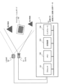
- FIG. 1 is a functional block diagram illustrating an outline of a configuration of an image point cloud data processing apparatus according to a first embodiment.
- FIG. 2 is a diagram illustrating an example of a hardware configuration of an image point cloud data processing device according to the first embodiment.
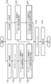
- 4 is a flowchart showing the operation of the image point cloud data processing device according to the first embodiment.
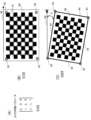
- 4A to 4C are explanatory diagrams showing the operation of the image data processing unit in the first embodiment.
- 5A to 5D are explanatory diagrams showing the operation of the point cloud data processing unit in the first embodiment.
- 5A and 5B are explanatory diagrams showing the operation of a registration processing unit in the first embodiment.
- 13 is a flowchart showing the operation of the image point cloud data processing device according to the second embodiment.
- FIG. 13A to 13C are explanatory diagrams showing the operation of an image data processing unit in the second embodiment.
- 13A to 13D are explanatory diagrams showing the operation of a point cloud data processing unit in embodiment 2.
- FIG. 13 is a diagram illustrating an example of a hardware configuration of an image point cloud data processing device according to a third embodiment.
- 13 is a flowchart showing the operation of the image point cloud data processing device according to the third embodiment.
- 5A to 5C are explanatory diagrams showing the operation of an image data processing unit in the embodiment.
- 13A to 13C are explanatory diagrams showing the operation of a point cloud data processing unit in embodiment 2.
- First embodiment 1 is a functional block diagram showing a schematic configuration of an image point cloud data processing device 1 according to the first embodiment.
- the image point cloud data processing device 1 is a device capable of implementing an image point cloud data processing method according to the first embodiment, and is, for example, a computer capable of executing an image point cloud data processing program according to the first embodiment.
- the image point cloud data processing device 1 is a device capable of deriving a transformation formula (i.e., a transformation matrix of the transformation formula) for converting image data obtained by shooting with a camera 51 as an imaging device and three-dimensional point cloud data detected by a LiDAR 52 (Light Detection And Ranging) as a distance measuring sensor into data in a common coordinate system.
- a transformation formula i.e., a transformation matrix of the transformation formula
- the image point cloud data processing device 1 has an image data processing unit 10, a point cloud data processing unit 20, and a registration processing unit 30.
- the image point cloud data processing device 1 may further have one or more of a data storage unit 40 which is a storage device that stores image data and three-dimensional point cloud data, a communication unit that communicates with external devices, and a display device that displays images.
- the image point cloud data processing device 1 determines a transformation matrix included in a transformation equation for converting image data obtained by the camera 51 and three-dimensional point cloud data detected by the LiDAR 52 into data in a common coordinate system in the real environment.
- the camera 51 and the LiDAR 52 are depicted as devices separate from the image point cloud data processing device 1, but the camera 51 and the LiDAR 52 may be part of the image point cloud data processing device 1.
- the image data processing unit 10 detects multiple image feature points (e.g., intersections of a checkered pattern) from the calibration pattern of the calibration board contained in the image data generated by the camera 51, and calculates image representative positions, which are multiple three-dimensional positions that represent the calibration board, based on the multiple image feature points.
- the multiple image representative positions are, for example, the corner positions of the calibration board.
- the point cloud data processing unit 20 detects an intra-area point cloud, which is a three-dimensional point cloud existing within a detection area determined based on an image representative position (e.g., a corner position of the calibration board), from the three-dimensional point cloud data indicating the three-dimensional point cloud generated by the LiDAR 52, and detects a representative point cloud representing the calibration board, which is a reference object, based on the intra-area point cloud.
- the calibration board has a predetermined calibration pattern.
- the calibration pattern is a checker pattern in which multiple rectangular white and black areas are alternately arranged two-dimensionally.
- the calibration pattern may also be a grid pattern consisting of multiple straight lines arranged in a square shape, a dot pattern consisting of multiple dots arranged two-dimensionally, etc.
- the registration processing unit 30 is a feature point matching processing unit that derives a transformation matrix of a transformation formula used to convert image data and 3D point cloud data by matching based on the image representative position calculated by the image data processing unit 10 and the representative point cloud detected by the point cloud data processing unit 20.
- the registration processing unit 30 calculates a transformation matrix using feature points from multiple images (e.g., the four corner points of the calibration board) and feature points of the 3D point cloud measured by the LiDAR 52 (e.g., the four corner points of the calibration board) by using the NDT (Normal Distribution Transform) method or the ICP (Iterative Closest Point) method.
- FIG. 2 is a diagram showing an example of the hardware configuration of the image point cloud data processing device 1 according to the first embodiment.
- the image point cloud data processing device 1 has, for example, a processor 101 such as a CPU (Central Processing Unit), a memory 102 as a storage unit, a storage device 103, and an interface 104.
- a processor 101 such as a CPU (Central Processing Unit)
- the processing circuit may be dedicated hardware, or may include a CPU that executes a program (for example, an image point cloud data processing program) stored in the memory 102.
- the processor 101 realizes each functional block shown in FIG. 1.
- the memory 102 is, for example, a semiconductor memory such as a RAM (Random Access Memory).
- the storage device 103 is a non-volatile storage device such as a HDD (Hard Disk Drive) or SSD (Solid State Drive).
- the image point cloud data processing device 1 may include both a component consisting of a circuit and a component consisting of a processor. A part or all of the image point cloud data processing device 1 may be a server computer on a network.
- the image point cloud data processing program is provided by downloading via the network or by a storage medium such as a USB memory that stores information.
- the interface 104 is connected to a camera 51, a LiDAR 52, an input device for user operations, a display device such as a liquid crystal display that presents information, and the like.
- the image point cloud data processing device 1 can convert image data and three-dimensional point cloud data into data in a common coordinate system with high accuracy by shooting and measuring a real space in which many objects exist. Furthermore, the image point cloud data processing device 1 can display on a display device an image in which a point cloud based on the three-dimensional point cloud data generated by the LiDAR 52 is superimposed on an image based on image data in the same coordinate system. Furthermore, the image point cloud data processing device 1 can display on a display device an image in which a surface constituted by a point cloud based on the three-dimensional point cloud data generated by the LiDAR 52 is colored based on the image data.
- FIGS. 3 is a flowchart showing the operation of the image point cloud data processing device 1 according to embodiment 1.
- FIGS. 3 is a flowchart showing the operation of the image point cloud data processing device 1 according to embodiment 1.
- the image data processing unit 10 acquires image data generated by the camera 51 (step S101), detects the calibration board 60 as a reference object included in the image data, performs camera calibration, and determines the camera internal parameters (step S102).
- Fig. 4A shows a transformation matrix as the camera internal parameters generated by the image data processing unit 10.
- ( cx , cy ) indicate the coordinates of the principal point (usually the center of the image), and fx and fy indicate focal lengths expressed in pixel units.
- the image data processing unit 10 detects a plurality of image feature points 61 from the calibration pattern of the calibration board 60 (step S103), and calculates image representative positions 63, which are a plurality of three-dimensional positions that represent the calibration board 60, based on the plurality of image feature points 61 (step S104).
- FIG. 4(B) shows the plurality of image feature points 61.
- FIG. 4(C) shows the image representative positions 63 at the four corner positions of the calibration board 60, obtained based on the plurality of image feature points 61.
- the image data processing unit 10 calculates the rotation angle ⁇ of the calibration board 60 with respect to the reference direction 65. Note that instead of the image representative positions 63, the corner positions 62 of the checker pattern, which is the calibration pattern of the calibration board 60, may be used.
- FIG. 5A to 5D are explanatory diagrams showing the operation of the point cloud data processing unit 20.
- the point cloud data processing unit 20 acquires a three-dimensional point cloud 71, which is a cluster generated by the LiDAR 52 and divided by a method such as clustering (step S105), and detects an intra-area point cloud 71a, which is a three-dimensional point cloud existing within a detection area 72 determined based on the image representative position 63 acquired from the image data processing unit 10 (step S106).
- FIG. 5A shows the three-dimensional point cloud 71 generated by the LiDAR 52.
- FIG. 5B shows the intra-area point cloud 71a, which is a three-dimensional point cloud existing within the detection area 72.
- Each point of the three-dimensional point cloud 71 is a measurement point irradiated with a laser beam.
- the point cloud data processing unit 20 detects a representative point cloud 73 representing the calibration board 60 based on the intra-area point cloud 71a (step S107).
- the representative point cloud is a point cloud made up of points indicating the positions of the corners of the calibration board 60.
- FIG. 5(C) shows the representative point cloud 73 calculated based on the intra-area point cloud 71a, which is a three-dimensional point cloud that exists within the detection area 72.
- FIG. 5(D) shows the distribution characteristics of the number of points with respect to reflection intensity used when detecting the calibration board 60.
- the point cloud data processing unit 20 can determine that an object having a distribution of the number of points similar to that of FIG. 5(D) (a distribution with two peaks) is the calibration board 60.
- FIG. 6A and 6B are explanatory diagrams showing the operation of the registration processing unit 30.
- the registration processing unit 30 performs matching between the image representative position 63 indicated by the three-dimensional data calculated by the image data processing unit 10 and the representative point group 73 indicated by the three-dimensional point cloud data calculated by the point cloud data processing unit 20, i.e., performs registration (step S108), and uses the result to calculate a transformation matrix of a transformation formula for converting the image data and the three-dimensional point cloud data into data of a common coordinate system (step S109).
- FIG. 6A shows registration
- FIG. 6B shows a transformation formula of a three-dimensional affine transformation between the image data and the three-dimensional point cloud data.
- the transformation formula is not limited to the three-dimensional affine transformation.
- the rotation angle ⁇ of the calibration board 60 is estimated based on the image data generated by the camera 51, the detection area of the three-dimensional point cloud data generated by the LiDAR 52 is rotated using the rotation angle ⁇ to extract the three-dimensional point cloud within the detection area, and registration is performed between the image representative position 63 and the representative point cloud 73, so that a highly accurate transformation matrix can be calculated.
- a highly accurate transformation matrix can be derived using image data and three-dimensional point cloud data of a real space in which objects other than the calibration board 60 exist.
- the image representative position 63 is a coordinate point at a corner of the calibration board 60
- the image representative position is a coordinate point on an edge (side) of the calibration board 60.
- Other points in the second embodiment are common to the first embodiment, so FIG. 1 and FIG. 2 will be referred to in the description of the second embodiment.
- FIG. 7 is a flowchart showing the operation of the image point cloud data processing device according to embodiment 2.
- the image point cloud data processing device according to embodiment 2 differs from the image point cloud data processing device 1 according to embodiment 1 in the processes of steps S204 and S207.
- Figures 8 (A) to (C) are explanatory diagrams showing the operation of the image data processing unit 10 in embodiment 2.
- the image data processing unit 10 acquires image data generated by the camera 51 (step S101), detects the calibration board 60 as a reference object contained in the image data, performs camera calibration, and determines the camera's internal parameters (step S102).
- Figure 8 (A) shows a transformation matrix as the camera's internal parameters generated by the image data processing unit 10, similar to Figure 4 (A).
- the image data processing unit 10 detects a plurality of image feature points 61 from the calibration pattern of the calibration board 60 (step S103), and calculates edges 64, which are a plurality of three-dimensional positions that represent the calibration board 60, based on the plurality of image feature points 61 (step S204).
- FIG. 8(B) shows a plurality of image feature points 61
- FIG. 8(C) calculates the position of the edge 64 of the calibration board 60 obtained based on the plurality of image feature points 61 as the image representative position.
- the image data processing unit 10 calculates the rotation angle ⁇ of the calibration board 60 with respect to the reference direction. Note that the position of the edge of the checker pattern, which is the calibration pattern of the calibration board 60, may be used instead of the image representative position 63.
- Figures 9 (A) to (C) are explanatory diagrams showing the operation of the point cloud data processing unit 20 in embodiment 2.
- the point cloud data processing unit 20 acquires a three-dimensional point cloud 71, which is a cluster generated by the LiDAR 52 and divided by a technique such as clustering (step S105), and detects an intra-area point cloud 71a, which is a three-dimensional point cloud existing within a detection area 72 determined based on the image representative position 63 acquired from the image data processing unit 10 (step S106).
- Figure 9 (A) shows the three-dimensional point cloud 71 generated by the LiDAR 52.
- Figure 9 (B) shows the intra-area point cloud 71a, which is a three-dimensional point cloud existing within the detection area 72.
- the point cloud data processing unit 20 detects a representative point cloud 74 of the edges that represent the calibration board 60 based on the intra-area point cloud 71a (step S207).
- the representative point cloud 74 is a point cloud that indicates the positions of the edges of the calibration board 60.
- FIG. 9(C) shows the representative point cloud 74 of the edges calculated based on the intra-area point cloud 71a, which is a three-dimensional point cloud that exists within the detection area 72.
- FIG. 9(D) shows the distribution characteristics of the number of points versus reflection intensity that are used when detecting the calibration board 60.
- the operation of the registration processing unit 30 is the same as in embodiment 1.
- FIG. 10 is a diagram showing an example of a hardware configuration of an image point cloud data processing device 3 according to the third embodiment.
- the same reference numerals as those shown in FIG. 2 are used for the same or corresponding components as those shown in FIG. 2.
- the reference object is a detection object (for example, a vehicle) 80.
- the detection object 80 does not need to have a calibration pattern that is a predetermined pattern.
- FIG. 11 is a flowchart showing the operation of the image point cloud data processing device 3 according to embodiment 2.
- the image point cloud data processing device 3 according to embodiment 3 differs from the image point cloud data processing device 1 according to embodiment 1 in the processes of steps S303, S304, S306, and S307.
- FIGS. 12(A) to (C) are explanatory diagrams showing the operation of the image data processing unit 10 in embodiment 3.
- the image data processing unit 10 acquires image data generated by the camera 51 (step S101), detects a detection object 80 (a vehicle in the figure) as a reference object contained in the image data, performs camera calibration, and determines the camera internal parameters (step S102).
- the image data processing unit 10 detects the detected object 80 from the image data using the color distribution of the image data as a feature, and estimates the depth of the detected object 80 (step S303).
- the object may be detected from the image data obtained by camera photography using deep learning, the depth may be estimated, and feature points may be obtained.
- the image data processing unit 10 extracts the edges, four corner points, and color distribution of the detected object 80 as feature quantities, and converts the image data from two-dimensional image data to three-dimensional image data (step S304).
- Figures 12 (A) and (B) show the process of calculating the detected object 80, multiple image representative positions 83, and the edges (sides) 81 of the detected object.
- Figure 12 (C) shows that since the detected object has light and dark shades, there is a specific tendency in the distribution of the number of pixels relative to the grayscale (tone) of the detected object (for example, there is a peak in the number of pixels at high gradations and a peak in the number of pixels at low gradations).
- FIGS. 13A to 13C are explanatory diagrams showing the operation of the point cloud data processing unit 20 in the third embodiment.
- the point cloud data processing unit 20 acquires a three-dimensional point cloud 91, which is a cluster generated by scanning the laser of the LiDAR 52 and divided by a method such as clustering (step S105), and detects an intra-area point cloud 91a, which is a three-dimensional point cloud existing in a detection area 92 determined based on the image representative position 83 or edge 81 acquired from the image data processing unit 10 (step S306).
- FIG. 13A shows the three-dimensional point cloud 91 generated by the LiDAR 52.
- FIG. 13B shows the intra-area point cloud 91a, which is a three-dimensional point cloud existing in the detection area 92.
- FIG. 13C shows that since the detected object has shading, there is a specific tendency in the distribution of the number of pixels for the grayscale (shading) of the detected object.
- the point cloud data processing unit 20 detects a representative edge point cloud 74 that represents the detected object 80 based on the intra-area point cloud 91a (step S307).
- the representative point cloud 94 is a point cloud that indicates the position of the edges of the detected object 80.
- FIG. 13(C) shows the representative edge point cloud 74 calculated based on the intra-area point cloud 71a, which is a three-dimensional point cloud that exists within the detection area 92.
- FIG. 13(D) shows the distribution characteristics of the number of points versus reflection intensity used when detecting the calibration board 60.
- Steps S108 and S109 which are the operations of the registration processing unit 30, are the same as in embodiment 1.
- a calibration board with a calibration pattern is not required, so by photographing and measuring the real space, the image data and the three-dimensional point cloud data can be converted into data in a common coordinate system.
- any of the first to third embodiments it is possible to photograph and measure a real space in which many objects exist, and to add color based on a color image to a surface formed by a three-dimensional point cloud generated by the LiDAR 52, for example. As a result, it becomes possible to display the surface formed by the three-dimensional point cloud in a format that is understandable to humans (for example, workers in the field of civil engineering).
- any of the first to third embodiments it is possible to photograph and measure a real space in which many objects exist, and to add color based on a color image to the points of the three-dimensional point cloud generated by the LiDAR 52, for example.
- Image point cloud data processing device 10 Image data processing unit, 20 Point cloud data processing unit, 30 Registration processing unit, 51 Camera, 52 LiDAR (ranging sensor), 60 Calibration board (reference object), 61 Image feature point, 63, 83 Image representative position, 64 Edge (image representative position), 71, 91 3D point cloud, 71a, 91a Area point cloud, 72, 92 Detection area, 73, 74, 94 Representative point cloud, 80 Detection object (reference object), 81 Edge (image feature point), 101 Processor, 102 Memory, 103 Storage device, 104 Interface.
Landscapes
- Engineering & Computer Science (AREA)
- Computer Vision & Pattern Recognition (AREA)
- Physics & Mathematics (AREA)
- General Physics & Mathematics (AREA)
- Theoretical Computer Science (AREA)
- Multimedia (AREA)
- Signal Processing (AREA)
- Human Computer Interaction (AREA)
- Length Measuring Devices By Optical Means (AREA)
- Studio Devices (AREA)
- Image Analysis (AREA)
- Image Processing (AREA)
Priority Applications (4)
| Application Number | Priority Date | Filing Date | Title |
|---|---|---|---|
| PCT/JP2023/002844 WO2024161453A1 (ja) | 2023-01-30 | 2023-01-30 | 画像点群データ処理装置、画像点群データ処理方法、及び画像点群データ処理プログラム |
| JP2024532198A JP7527532B1 (ja) | 2023-01-30 | 2023-01-30 | 画像点群データ処理装置、画像点群データ処理方法、及び画像点群データ処理プログラム |
| CN202380081109.XA CN120530647A (zh) | 2023-01-30 | 2023-01-30 | 图像点群数据处理装置、图像点群数据处理方法和图像点群数据处理程序 |
| US19/210,465 US20250278859A1 (en) | 2023-01-30 | 2025-05-16 | Image point cloud data processing device, image point cloud data processing method, and storage medium storing image point cloud data processing program |
Applications Claiming Priority (1)
| Application Number | Priority Date | Filing Date | Title |
|---|---|---|---|
| PCT/JP2023/002844 WO2024161453A1 (ja) | 2023-01-30 | 2023-01-30 | 画像点群データ処理装置、画像点群データ処理方法、及び画像点群データ処理プログラム |
Related Child Applications (1)
| Application Number | Title | Priority Date | Filing Date |
|---|---|---|---|
| US19/210,465 Continuation US20250278859A1 (en) | 2023-01-30 | 2025-05-16 | Image point cloud data processing device, image point cloud data processing method, and storage medium storing image point cloud data processing program |
Publications (1)
| Publication Number | Publication Date |
|---|---|
| WO2024161453A1 true WO2024161453A1 (ja) | 2024-08-08 |
Family
ID=91969350
Family Applications (1)
| Application Number | Title | Priority Date | Filing Date |
|---|---|---|---|
| PCT/JP2023/002844 Ceased WO2024161453A1 (ja) | 2023-01-30 | 2023-01-30 | 画像点群データ処理装置、画像点群データ処理方法、及び画像点群データ処理プログラム |
Country Status (4)
| Country | Link |
|---|---|
| US (1) | US20250278859A1 (https=) |
| JP (1) | JP7527532B1 (https=) |
| CN (1) | CN120530647A (https=) |
| WO (1) | WO2024161453A1 (https=) |
Families Citing this family (1)
| Publication number | Priority date | Publication date | Assignee | Title |
|---|---|---|---|---|
| JP2025080816A (ja) * | 2023-11-15 | 2025-05-27 | 株式会社日立製作所 | センシング装置、センシング方法、及び、センシングシステム |
Citations (3)
| Publication number | Priority date | Publication date | Assignee | Title |
|---|---|---|---|---|
| JP2022039906A (ja) * | 2020-08-28 | 2022-03-10 | 中国計量大学 | マルチセンサによる複合キャリブレーション装置及び方法 |
| WO2022209166A1 (ja) * | 2021-03-31 | 2022-10-06 | ソニーグループ株式会社 | 情報処理装置、情報処理方法、及び較正用ターゲット |
| JP2022157096A (ja) * | 2021-03-31 | 2022-10-14 | 株式会社Subaru | 車両の走行制御装置 |
Family Cites Families (1)
| Publication number | Priority date | Publication date | Assignee | Title |
|---|---|---|---|---|
| JP2016057108A (ja) * | 2014-09-08 | 2016-04-21 | 株式会社トプコン | 演算装置、演算システム、演算方法およびプログラム |
-
2023
- 2023-01-30 WO PCT/JP2023/002844 patent/WO2024161453A1/ja not_active Ceased
- 2023-01-30 JP JP2024532198A patent/JP7527532B1/ja active Active
- 2023-01-30 CN CN202380081109.XA patent/CN120530647A/zh active Pending
-
2025
- 2025-05-16 US US19/210,465 patent/US20250278859A1/en active Pending
Patent Citations (3)
| Publication number | Priority date | Publication date | Assignee | Title |
|---|---|---|---|---|
| JP2022039906A (ja) * | 2020-08-28 | 2022-03-10 | 中国計量大学 | マルチセンサによる複合キャリブレーション装置及び方法 |
| WO2022209166A1 (ja) * | 2021-03-31 | 2022-10-06 | ソニーグループ株式会社 | 情報処理装置、情報処理方法、及び較正用ターゲット |
| JP2022157096A (ja) * | 2021-03-31 | 2022-10-14 | 株式会社Subaru | 車両の走行制御装置 |
Also Published As
| Publication number | Publication date |
|---|---|
| JPWO2024161453A1 (https=) | 2024-08-08 |
| JP7527532B1 (ja) | 2024-08-02 |
| CN120530647A (zh) | 2025-08-22 |
| US20250278859A1 (en) | 2025-09-04 |
Similar Documents
| Publication | Publication Date | Title |
|---|---|---|
| JP6363863B2 (ja) | 情報処理装置および情報処理方法 | |
| CN103649674B (zh) | 测量设备以及信息处理设备 | |
| JP5633058B1 (ja) | 3次元計測装置及び3次元計測方法 | |
| JP4885584B2 (ja) | レンジファインダ校正方法及び装置 | |
| JP6256475B2 (ja) | 画像処理装置、画像処理方法および画像処理プログラム | |
| KR101589167B1 (ko) | 깊이 정보를 이용한 원근 왜곡 영상의 보정 시스템 및 방법 | |
| JPWO2018235163A1 (ja) | キャリブレーション装置、キャリブレーション用チャート、チャートパターン生成装置、およびキャリブレーション方法 | |
| JP2012058076A (ja) | 3次元計測装置及び3次元計測方法 | |
| KR102023087B1 (ko) | 카메라 캘리브레이션 방법 | |
| CN110136114A (zh) | 一种波面高度测量方法、终端设备及存储介质 | |
| JP2011155412A (ja) | 投影システムおよび投影システムにおける歪み修正方法 | |
| CN108362205B (zh) | 基于条纹投影的空间测距方法 | |
| CN111489384A (zh) | 基于互视角的遮挡评估方法及装置、设备、系统和介质 | |
| US20250278859A1 (en) | Image point cloud data processing device, image point cloud data processing method, and storage medium storing image point cloud data processing program | |
| CN117671031A (zh) | 双目相机标定方法、装置、设备及存储介质 | |
| CN109506629A (zh) | 一种水下核燃料组件检测装置旋转中心标定的方法 | |
| JP2022128087A (ja) | 計測システム及び計測プログラム | |
| CN108629840A (zh) | 一种建立logo三维轮廓的方法、装置和设备 | |
| JP2018009927A (ja) | 画像処理装置、画像処理方法及びプログラム | |
| KR100933304B1 (ko) | 단일 카메라를 이용한 객체 정보 추정기, 그 방법, 상기 추정기를 포함하는 멀티미디어 기기 및 컴퓨터 기기, 및 상기 방법을 수행하기 위한 프로그램을 기록한 컴퓨터로 판독 가능한 기록매체 | |
| JP7020240B2 (ja) | 認識装置、認識システム、プログラムおよび位置座標検出方法 | |
| JP2009146150A (ja) | 特徴位置検出方法及び特徴位置検出装置 | |
| CN115049711B (zh) | 图像配准方法、装置、电子设备及介质 | |
| JP6867766B2 (ja) | 情報処理装置およびその制御方法、プログラム | |
| JP7799499B2 (ja) | 計測システム、計測方法及び計測プログラム |
Legal Events
| Date | Code | Title | Description |
|---|---|---|---|
| WWE | Wipo information: entry into national phase |
Ref document number: 2024532198 Country of ref document: JP |
|
| 121 | Ep: the epo has been informed by wipo that ep was designated in this application |
Ref document number: 23919598 Country of ref document: EP Kind code of ref document: A1 |
|
| WWE | Wipo information: entry into national phase |
Ref document number: 202380081109.X Country of ref document: CN |
|
| WWP | Wipo information: published in national office |
Ref document number: 202380081109.X Country of ref document: CN |
|
| NENP | Non-entry into the national phase |
Ref country code: DE |
|
| 122 | Ep: pct application non-entry in european phase |
Ref document number: 23919598 Country of ref document: EP Kind code of ref document: A1 |