WO2024157992A1 - 冷却装置および搬送方法 - Google Patents
冷却装置および搬送方法 Download PDFInfo
- Publication number
- WO2024157992A1 WO2024157992A1 PCT/JP2024/001962 JP2024001962W WO2024157992A1 WO 2024157992 A1 WO2024157992 A1 WO 2024157992A1 JP 2024001962 W JP2024001962 W JP 2024001962W WO 2024157992 A1 WO2024157992 A1 WO 2024157992A1
- Authority
- WO
- WIPO (PCT)
- Prior art keywords
- tank
- cooling
- raw milk
- cooling water
- liquid
- Prior art date
- Legal status (The legal status is an assumption and is not a legal conclusion. Google has not performed a legal analysis and makes no representation as to the accuracy of the status listed.)
- Ceased
Links
Images




Classifications
-
- A—HUMAN NECESSITIES
- A01—AGRICULTURE; FORESTRY; ANIMAL HUSBANDRY; HUNTING; TRAPPING; FISHING
- A01J—MANUFACTURE OF DAIRY PRODUCTS
- A01J11/00—Apparatus for treating milk
-
- A—HUMAN NECESSITIES
- A01—AGRICULTURE; FORESTRY; ANIMAL HUSBANDRY; HUNTING; TRAPPING; FISHING
- A01J—MANUFACTURE OF DAIRY PRODUCTS
- A01J9/00—Milk receptacles
- A01J9/04—Milk receptacles with cooling arrangements
-
- A—HUMAN NECESSITIES
- A23—FOODS OR FOODSTUFFS; TREATMENT THEREOF, NOT COVERED BY OTHER CLASSES
- A23B—PRESERVATION OF FOODS, FOODSTUFFS OR NON-ALCOHOLIC BEVERAGES; CHEMICAL RIPENING OF FRUIT OR VEGETABLES
- A23B2/00—Preservation of foods or foodstuffs, in general
- A23B2/80—Freezing; Subsequent thawing; Cooling
-
- F—MECHANICAL ENGINEERING; LIGHTING; HEATING; WEAPONS; BLASTING
- F25—REFRIGERATION OR COOLING; COMBINED HEATING AND REFRIGERATION SYSTEMS; HEAT PUMP SYSTEMS; MANUFACTURE OR STORAGE OF ICE; LIQUEFACTION SOLIDIFICATION OF GASES
- F25D—REFRIGERATORS; COLD ROOMS; ICE-BOXES; COOLING OR FREEZING APPARATUS NOT OTHERWISE PROVIDED FOR
- F25D11/00—Self-contained movable devices, e.g. domestic refrigerators
Definitions
- the present invention relates to a cooling device and a transportation method.
- Patent Document 1 describes a refrigerator equipped with a refrigerating compartment.
- the object of the present invention is to provide a cooling device and a transportation method that can efficiently cool objects.
- a cooling tank into which a tank for storing liquid is inserted; a fixing part for pressing down the tank from above and immersing the tank in the cooling water when the cooling water is stored in the cooling tank; a cooling unit for cooling the cooling water.
- a cooling device as described in (1) above which is disposed within the cooling tank and has a guide for positioning the tank.
- the cooling device of the present invention immerses the tank in cooling water and uses the cooling water to cool the liquid in the tank, so the liquid in the tank can be cooled efficiently.
- the transport method of the present invention allows the liquid to be cooled in a shorter time, and the liquid can be transported in a cold state. This makes it possible to suppress the growth of bacteria in the liquid.
- FIG. 1 is a cross-sectional view of a cooling device according to a preferred embodiment.
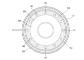
- FIG. 2 is a top view showing the inside of the cooling tank of the cooling device.
- FIG. 3 is a cross-sectional view showing a state in which the tank is disposed in the cooling device.
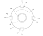
- FIG. 4 is a top view showing a method of fixing the fixing portion and the main body portion.
- FIG. 5 is a flow chart showing a method for transporting raw milk.
- FIG. 6 is a schematic diagram showing a method for transporting raw milk.
- the cooling device 100 shown in Fig. 1 is a device for cooling liquid, particularly raw milk.
- the liquid is not limited to raw milk, and may be, for example, various beverages such as fruit or vegetable juice, or high-viscosity foods such as jam or margarine.
- the liquid is not limited to beverages or foods, and may be, for example, reagents, fuel, etc.
- the cooling device 100 has a main body 110, a cooling tank 120 that opens on the top of the main body 110 and into which a tank 200 for raw milk is inserted, cooling water 130 stored in the cooling tank 120, a pump 180 that circulates the cooling water 130, a fixing part 140 that fixes the tank 200 inserted into the cooling tank 120, a cooling unit 150 that cools the cooling water 130, a guide 160 that is arranged in the cooling tank 120 and positions the tank 200, and an agitator 170 that agitates the raw milk in the tank 200.
- the tank 200 is a tank for storing raw milk.
- the tank 200 has a cylindrical large diameter section 210 located at the lower end, a cylindrical small diameter section 220 located at the upper end, and a tapered section 230 located between the large diameter section 210 and the small diameter section 220 and connecting them.
- the capacity of the tank 200 is about 40 L.
- the tank 200 is made of various metal materials such as aluminum and stainless steel. Tanks 200 of this shape and capacity are widely used, particularly in India (Republic of India). However, the configuration of the tank 200 is not particularly limited.
- the cooling tank 120 is covered with a heat insulating material 121. This allows the cooling water 130 in the cooling tank 120 to be cooled efficiently.
- the cooling water 130 in the cooling tank 120 is not particularly limited, but is preferably non-toxic to living organisms, taking into consideration the possibility of it being mixed into the tank 200. Examples of such cooling water 130 include, but are not particularly limited to, calcium chloride aqueous solution, sodium chloride aqueous solution, various alcohols, water, etc.
- alcohol is prone to evaporation and requires regular replenishment, which makes the cooling process complicated. There is also a risk of failure to cool the raw milk due to insufficient replenishment.
- a calcium chloride aqueous solution is used. This results in cooling water 130 that is less likely to evaporate and has a sufficiently low freezing point.
- a calcium chloride aqueous solution with a concentration of approximately 26% is used, and this is cooled to a minimum temperature of -20°C. This allows the raw milk to be cooled more quickly.
- the cooling water 130 becomes inexpensive and is easy to prepare.
- the water that is the cooling water 130 is cooled by the cooling unit 150, and a portion of it (the portion around the evaporator 154 described below) is frozen to generate ice that adheres to the evaporator 154, and the raw milk in the tank 200 can be efficiently cooled by the latent heat of the ice.
- corrosion of the cooling device 100 and the tank 200 can be effectively suppressed.
- the cooling water 130 in the cooling tank 120 is circulated by the pump 180. This increases the efficiency of heat exchange between the cooling water 130 and the raw milk in the tank 200, allowing the raw milk in the tank 200 to be cooled in a shorter time.
- the cooling unit 150 cools the cooling water 130.
- the cooling unit 150 has a compressor 151, a condenser 152, an expansion valve 153, an evaporator 154, a pipe 155 connecting them, and a refrigerant filled in the pipe 155.
- the evaporator 154 is exposed in the cooling tank 120 and is in contact with the cooling water 130. This allows efficient heat exchange between the evaporator 154 and the cooling water 130.
- the compressor 151 the refrigerant is compressed into a high-temperature, high-pressure gas.
- the condenser 152 the refrigerant releases heat and becomes a high-temperature, high-pressure liquid.
- the refrigerant In the expansion valve 153, the refrigerant is decompressed and becomes a low-temperature, low-pressure liquid. In the evaporator 154, the refrigerant absorbs heat from the cooling water 130 and becomes a low-temperature, low-pressure gas. The low-temperature, low-pressure gaseous refrigerant is then compressed again by the compressor 151 and becomes a high-temperature, high-pressure gas. By repeating this heat exchange cycle, the cooling water 130 in the cooling tank 120 is cooled, and the raw milk in the tank 200 is cooled by the cooled cooling water 130. In this way, by immersing the tank 200 in the cooling water 130, the raw milk in the tank 200 can be efficiently cooled.
- the cooling tank 120 is cylindrical and is larger than the large diameter portion 210 of the tank 200.
- the shape of the cooling tank 120 is not particularly limited.
- the guide 160 arranged in the cooling tank 120 has the function of guiding and holding the tank 200 to the center of the cooling tank 120.
- the guide 160 is located inside the evaporator 154 and is configured by arranging multiple rods 161 extending vertically in a circular shape, and its inner diameter is slightly larger than the outer diameter of the large diameter portion 210.
- adjacent rods 161 are spaced apart from each other, and the cooling water 130 flows inside and outside the guide 160 through this gap.
- Such a guide 160 is arranged concentrically with the cooling tank 120, and by inserting the tank 200 into the guide 160, the tank 200 is guided to the center of the cooling tank 120 and held therein. This allows the raw milk in the tank 200 to be efficiently cooled from the entire circumference of the tank 200.
- the fixing part 140 is used to press down the tank 200 from above, and the tank 200 is fully immersed in the cooling water 130.
- the fixing part 140 is plate-shaped, and has an insertion hole 141 in the center through which the tank 200 passes.
- the diameter of the insertion hole 141 is larger than the small diameter part 220 and smaller than the large diameter part 210. Therefore, when the tank 200 is inserted into the insertion hole 141, the tapered part 230 of the tank 200 gets caught on the fixing part 140.
- the tank 200 is pressed down from above, preventing it from floating up and deeply immersed in the cooling water 130. In this state, almost the entire outer circumferential surface of the tank 200 comes into contact with the cooling water 130. In this way, by immersing the tank 200 in the cooling water 130, the raw milk in the tank 200 can be efficiently cooled.
- the method of fixing the fixing part 140 to the main body 110 is not particularly limited.
- the main body 110 has four claw parts 111 arranged at equal intervals around the cooling tank 120.
- the fixing part 140 has four notches 142 formed at equal intervals around the periphery. The four notches 142 are formed to overlap with the four claw parts 111.
- the fixing part 140 is fixed to the main body 110 by passing the claw parts 111 through the notches 412 and pushing the fixing part 140 below the claw parts 111, and then rotating the fixing part 140 in this state to shift the notches 142 from the claw parts 111.
- the raw milk in the tank 200 is stirred by the stirrer 170 while being cooled. This allows the raw milk to be cooled uniformly and quickly while suppressing clumping of the raw milk.
- the configuration of the stirrer 170 is not particularly limited, and for example, a wave pump (water flow pump) can be used.
- the cooling characteristics of the cooling device 100 are not particularly limited, but it is preferable that the cooling device 100 has the characteristic of being able to cool 40 L of raw milk stored in the tank 200 at about 36°C to 3°C or less within 30 minutes at an outside air temperature of 30°C. This allows the raw milk to be cooled to 10°C or less in a shorter time after milking, and effectively suppresses the growth of bacteria in the raw milk. It is also preferable that the power required for one cooling cycle, that is, to cool 40 L of raw milk stored in the tank 200 to 3°C or less, is 4 kW or less. This allows sufficient power to be provided by a small storage battery. Therefore, even in areas where electricity is not supplied or the supply of electricity is unstable, the cooling device 100 can be operated by the storage battery to cool the raw milk. The storage battery can be charged by connecting it to a solar panel or the like.
- the transport method is a method for transporting raw milk M to a milk production plant or the like, and includes a cooling step S1 of cooling the raw milk M in a tank 200 using the cooling device 100, a first transport step S2 of storing the tank 200 in a cold storage case 300 and transporting it, a second transport step S3 of transferring the raw milk M in the tank 200 to a large storage tank 510 and transporting it, and a milk production step S4 of processing the raw milk M to produce milk.
- the cooling step S1 is performed at each of a plurality of small-scale collection stations L1. At least one cooling device 100 is provided at each small-scale collection station L1. A dairy farmer Q (a person who keeps dairy cows) brings milked raw milk M to the nearest small-scale collection station L1 and pours it into a tank 200 set in the cooling device 100. As a result, the raw milk in the tank 200 is cooled by the cooling device 100 to 5°C or less, preferably 3°C or less. However, the cooling temperature of the raw milk is not particularly limited.
- the cold storage case 300 is not particularly limited as long as it can suppress the temperature rise of the raw milk M in the tank 200 compared to when the tank 200 is left uncovered, but it can be made of, for example, a polystyrene foam case. This makes it possible to suppress the temperature rise of the raw milk M in the tank 200 and maintain a low temperature (10° C. or less) for a longer period of time.
- the collection truck 400 goes around each small-scale collection point L1 in turn, collects the tanks 200 stored in the refrigerated cases 300, and transports them to the large-scale collection point L2.
- the collection truck 400 is not equipped with the function of cooling the raw milk M. Therefore, by storing the tanks 200 in the refrigerated cases 300, it is possible to suppress the proliferation of bacteria in the raw milk M due to an increase in temperature (a state in which the raw milk M is unacceptable as raw milk). It is preferable to end the first transport step S2 when the temperature of the raw milk M is below 10°C. This makes it possible to effectively suppress the proliferation of bacteria in the raw milk M.
- the first transport step S2 is not particularly limited, and the tank 200 may be transported to the large-scale collection point L2 without being stored in the refrigerated case 300.
- the collection method is also not particularly limited, and may be collected by motorcycle (two-wheeled vehicle), for example.
- the raw milk M collected by the collection truck 400 is transferred to the large storage tank 510.
- a plurality of collection trucks 400 travel around the small-scale collection sites L1 in the surrounding areas, and each of these collection trucks 400 transports the collected raw milk M to the large-scale collection site L2, where the collected raw milk M is transferred to the large storage tank 510. In this way, the raw milk M collected from each area can be transported together.
- the large storage tank 510 has a larger capacity than the tank 200.
- the large storage tank 510 is a tank of a tank truck 500.
- the raw milk M is transported to the milk production plant 600 by the tank truck 500.
- the large storage tank 510 is equipped with a cooling unit that cools the raw milk M in the large storage tank 510. This allows the raw milk M in the large storage tank 510 to be transported to the milk production plant 600 while being cooled, so that the temperature rise (bacteria growth) of the raw milk M during the second transport step S3 can be effectively suppressed.
- the raw milk Before transferring the raw milk to the large storage tank 510 at the large-scale collection site L2, the raw milk may be cooled again using a large cooling device (a cooling device different from the cooling device 100) installed at the large-scale collection site L2. This allows the raw milk to be kept at a sufficiently low temperature until it is transported to the milk production plant 600, even if the large storage tank 510 is not equipped with a cooling unit.
- a large cooling device a cooling device different from the cooling device 100
- the raw milk M collected from the small-scale collection site L1 was finally cooled when it was transferred to the large storage tank 510 at the large-scale collection site L2. Therefore, the raw milk M was exposed to high temperatures until it was transferred to the large storage tank 510, and there was a high risk of bacteria growing in the raw milk M.
- the low-quality raw milk M in which bacteria had grown was placed directly in the large storage tank 510, which also caused a decrease in the quality of the entire raw milk M in the large storage tank 510.
- the raw milk M is cooled before the first transport step S2, so the growth of bacteria in the raw milk M can be effectively suppressed compared to the past.
- the raw milk M is cooled once in the cooling step S1, and the temperature of the raw milk M at that time is lower than in the past, so energy saving in cooling here (power saving, shortening of throughput time, etc.) can be achieved.
- ⁇ Milk production step S4> In the milk production step S4, first, the transported raw milk M is inspected to see if it is acceptable as raw milk. Raw milk M that passes the inspection is cooled to 10°C or less in a cooling machine and sent to a milk storage tank. Next, garbage, foreign matter, etc. in the raw milk M are separated and removed using a centrifugal separator, a filter, etc. Next, the raw milk M is homogenized to break milk fat globules into fine particles. Next, the raw milk M is heated to kill the sterilization, and immediately after sterilization, it is cooled to 10°C or less. The sterilized raw milk M is temporarily stored in a milk storage tank, and then filled into milk containers, and milk that passes the shipping inspection is shipped from the milk factory.
- This transportation method allows the raw milk M to be cooled as quickly as possible after milking, and further allows the raw milk to be transported to the milk production plant 600 while still being sufficiently cold. This prevents deterioration in the quality of the raw milk M, and increases the amount that can be accepted as raw milk.
- cooling device and transport method of the present invention have been described above based on the illustrated embodiment, but the present invention is not limited to this.
- the configuration of each part can be replaced with any configuration that performs the same function, and any configuration or process can be added.
- the cooling device of the present invention comprises a cooling tank into which a tank for storing liquid is inserted, a fixing part that holds down the tank from above while cooling water is stored in the cooling tank, and a cooling unit that cools the cooling water.
- a cooling tank into which a tank for storing liquid is inserted, a fixing part that holds down the tank from above while cooling water is stored in the cooling tank, and a cooling unit that cools the cooling water.
- the transport method of the present invention also includes a cooling step of cooling the liquid in the tank using the cooling device, a first transport step of transporting the tank, and a second transport step of transferring the liquid in the tank to a large storage tank and transporting it.
Landscapes
- Life Sciences & Earth Sciences (AREA)
- Engineering & Computer Science (AREA)
- Environmental Sciences (AREA)
- Animal Husbandry (AREA)
- Chemical & Material Sciences (AREA)
- Combustion & Propulsion (AREA)
- Polymers & Plastics (AREA)
- Food Science & Technology (AREA)
- Wood Science & Technology (AREA)
- Zoology (AREA)
- Physics & Mathematics (AREA)
- Mechanical Engineering (AREA)
- Thermal Sciences (AREA)
- General Engineering & Computer Science (AREA)
- Freezing, Cooling And Drying Of Foods (AREA)
- Devices That Are Associated With Refrigeration Equipment (AREA)
Abstract
対象物を効率的に冷却することができる。 冷却装置1は、生乳を貯留するタンク7を挿入する冷却槽3と、冷却槽3内に貯留された冷却水4と、タンク7を上側から押さえつけ、冷却水4内に浸漬させた状態を維持する固定部8と、冷却水4を冷却する冷却ユニット5と、冷却槽3内に配置され、タンク7を位置決めするガイド部6と、を有する。また、冷却水4は、塩化カルシウム水溶液である。
Description
本発明は、冷却装置および搬送方法に関する。
例えば、特許文献1には、冷蔵室を備える冷却庫が記載されている。
しかしながら、特許文献1の冷却庫では、冷蔵室内の空気を冷やすことで、冷蔵室内の対象物を冷却するため、対象物を効率的に冷却することができない。
本発明の目的は、対象物を効率的に冷却することのできる冷却装置および搬送方法を提供することにある。
このような目的は、下記の本発明により達成される。
(1) 液体を貯留するタンクを挿入する冷却槽と、
前記冷却槽内に冷却水を貯めた状態で、前記タンクを上側から押さえつけて前記冷却水内に浸漬した状態とする固定部と、
前記冷却水を冷却する冷却ユニットと、を有することを特徴とする冷却装置。
前記冷却槽内に冷却水を貯めた状態で、前記タンクを上側から押さえつけて前記冷却水内に浸漬した状態とする固定部と、
前記冷却水を冷却する冷却ユニットと、を有することを特徴とする冷却装置。
(2) 前記冷却槽内に配置され、前記タンクを位置決めするガイドを有する上記(1)に記載の冷却装置。
(3) 前記冷却水は、塩化カルシウム水溶液である上記(1)に記載の冷却装置。
(4) 前記液体は、生乳である上記(1)に記載の冷却装置。
(5) 上記(1)ないし(4)のいずれかに記載の冷却装置を用いて前記タンク内の前記液体を冷却する冷却ステップと、
前記タンクを搬送する第1搬送ステップと、
前記タンク内の前記液体を大型貯留槽に移し替えて搬送する第2搬送ステップと、を有することを特徴とする搬送方法。
前記タンクを搬送する第1搬送ステップと、
前記タンク内の前記液体を大型貯留槽に移し替えて搬送する第2搬送ステップと、を有することを特徴とする搬送方法。
(6) 前記第1搬送ステップを前記液体の温度が10℃以下の状態で終える上記(5)に記載の搬送方法。
(7) 複数個所において前記冷却ステップを行い、
前記第1搬送ステップでは、前記複数個所を順に経由して前記タンクを回収する上記(5)に記載の搬送方法。
前記第1搬送ステップでは、前記複数個所を順に経由して前記タンクを回収する上記(5)に記載の搬送方法。
本発明の冷却装置によれば、冷却水にタンクを浸漬させ、冷却水を用いてタンク内の液体を冷却するため、タンク内の液体を効率的に冷却することができる。
また、本発明の搬送方法によれば、より短時間で液体を冷却することができ、冷えた状態で液体を搬送することができる。そのため、液体中の細菌の増加を抑制することができる。
以下、本発明の冷却装置および搬送方法を添付図面に示す実施形態に基づいて詳細に説明する。
[冷却装置100]
図1に示す冷却装置100は、液体、特に生乳を冷却する装置である。なお、液体としては、生乳に限定されず、例えば、果実や野菜の汁(ジュース)などの各種飲料や、ジャム、マーガリン等の高粘度の食品であってもよい。また、飲料、食品に限定されず、例えば、試薬、燃料等であってもよい。
図1に示す冷却装置100は、液体、特に生乳を冷却する装置である。なお、液体としては、生乳に限定されず、例えば、果実や野菜の汁(ジュース)などの各種飲料や、ジャム、マーガリン等の高粘度の食品であってもよい。また、飲料、食品に限定されず、例えば、試薬、燃料等であってもよい。
冷却装置100は、本体110と、本体110の上面に開口し、生乳用のタンク200が挿入される冷却槽120と、冷却槽120内に貯められた冷却水130と、冷却水130を循環させるポンプ180と、冷却槽120に挿入されたタンク200を固定する固定部140と、冷却水130を冷却する冷却ユニット150と、冷却槽120内に配置され、タンク200の位置決めを行うガイド160と、タンク200内の生乳を撹拌する撹拌機170と、を有する。
タンク200は、生乳を貯留するタンクである。タンク200は、下端部に位置する円筒状の大径部210と、上端部に位置する円筒状の小径部220と、大径部210と小径部220との間に位置し、これらを接続するテーパ部230と、を有する。また、タンク200の容量は、40L程度である。また、タンク200は、例えば、アルミニウム、ステンレス鋼等の各種金属材料で構成されている。このような形状および容量のタンク200は、特に、インド(インド共和国)国内において広く使用されている。ただし、タンク200の構成は、特に限定されない。
冷却槽120は、断熱材121で覆われている。これにより、冷却槽120内の冷却水130を効率的に冷却することができる。また、冷却槽120内の冷却水130としては、特に限定されないが、タンク200内に混入する可能性を考慮して、生体に対して毒性のないものが好ましい。このような冷却水130としては、特に限定されないが、例えば、塩化カルシウム水溶液、塩化ナトリウム水溶液、各種アルコール、水等が挙げられる。
これらの中でも、タンク200の腐食防止等の観点から冷却水130としてアルコールを用いることが好ましいが、アルコールは、揮発し易く定期的な補充が必要となり冷却作業が煩雑となる。また、補充不足より生乳の冷却が失敗するおそれもある。なお、冷却ユニット150を常時駆動してアルコールを十分に冷やした状態を保つことによりアルコールの揮発を抑えることができるものの、その分、消費電力が増大してしまう。そこで、本実施形態では、塩化カルシウム水溶液を用いている。これにより、揮発し難く、かつ、凝固点が十分に低い冷却水130となる。特に、濃度約26%の塩化カルシウム水溶液を用い、これを-20℃を最下限温度として冷却する。これにより、生乳をより迅速に冷却することができる。
また、冷却水130として水を用いることにより、冷却水130が安価となると共に冷却水130を準備し易くなる。この場合、冷却ユニット150によって冷却水130である水を冷却し、その一部(後述する蒸発器154の周囲にある部分)を凍らせて、蒸発器154に付着した氷を生成することにより、当該氷の潜熱によってタンク200内の生乳を効率的に冷却することができる。さらには、冷却水130として水を用いることにより、冷却装置100やタンク200の腐食を効果的に抑制することができる。
冷却槽120内の冷却水130は、ポンプ180によって循環される。これにより、冷却水130とタンク200内の生乳との熱交換効率が高まり、タンク200内の生乳をより短時間で冷却することができる。
冷却ユニット150は、冷却水130を冷却する。冷却ユニット150は、圧縮機151と、凝縮器152と、膨張弁153と、蒸発器154と、これらを繋ぐ管路155と、管路155内に充填された冷媒と、を有する。また、蒸発器154は、冷却槽120内に露出しており、冷却水130と接触している。これにより、蒸発器154と冷却水130とで効率的な熱交換が行われる。圧縮機151では、冷媒が圧縮されて高温高圧のガス状となる。また、凝縮器152では、冷媒が放熱されて高温高圧の液状となる。また、膨張弁153では、冷媒が減圧されて低温低圧の液状となる。また、蒸発器154では、冷媒が冷却水130の熱を吸収して低温低圧のガス状となる。そして、低温低圧ガス状の冷媒が圧縮機151で再び圧縮されて高温高圧のガス状となる。このような熱交換サイクルを繰り返すことにより、冷却槽120の冷却水130を冷やし、冷えた冷却水130によってタンク200内の生乳を冷却する。このように、冷却水130にタンク200を浸漬させることにより、タンク200内の生乳を効率的に冷却することができる。
冷却槽120は、円筒形であり、タンク200の大径部210よりも大きく形成されている。ただし、冷却槽120の形状は、特に限定されない。このような冷却槽120内に配置されたガイド160は、タンク200を冷却槽120の中心に案内して保持する機能を有する。図1および図2に示すように、ガイド160は、蒸発器154の内側に位置し、鉛直方向に延びる複数の棒材161を円状に配置した構成であり、その内径が大径部210の外径よりも若干大きい。また、隣り合う棒材161同士が離間しており、この隙間を介してガイド160の内外に冷却水130が流動する。このようなガイド160は、冷却槽120と同心的に配置されており、ガイド160内にタンク200を挿入することにより、タンク200が冷却槽120の中心に案内され、保持される。これにより、タンク200の生乳をタンク200の全周から効率的に冷却することができる。
タンク200は、冷却水130に浮いてしまうため、固定部140を用いてタンク200を上側から押さえ付け、タンク200を冷却水130内に十分に浸漬させる。図1に示すように、固定部140は、板状であり、その中央部にタンク200を挿通する挿通孔141を有する。挿通孔141の径は、小径部220よりも大きく大径部210よりも小さい。そのため、タンク200を挿通孔141に挿入すると、タンク200のテーパ部230が固定部140に引っ掛かる。
図3に示すように、挿通孔141にタンク200を挿入した状態で固定部140を本体110に固定することにより、タンク200が上側から押さえつけられ、浮き上がりが防止されて冷却水130内に深く浸漬する。この状態では、タンク200の外周面のほぼ全域が冷却水130と接触する。このように、タンク200を冷却水130に浸漬させることにより、タンク200内の生乳を効率的に冷却することができる。
なお、固定部140と本体110との固定方法は、特に限定されない。本実施形態では、図3に示すように、本体110は、冷却槽120の周囲に等間隔に配置された4つの爪部111を有する。一方、固定部140は、その周囲に等間隔に形成された4つの切り欠き142を有する。4つの切り欠き142は、4つの爪部111と重なるように形成されている。このような構成では、切り欠き412内に爪部111を通過させて固定部140を爪部111の下方まで押し込み、その状態で固定部140を回転させて切り欠き142を爪部111からずらすことにより、固定部140が本体110に固定される。
タンク200の生乳は、冷却中、撹拌機170により撹拌される。これにより、生乳の凝集を抑制しつつ、生乳を均一かつ迅速に冷却することができる。なお、撹拌機170の構成は、特に限定されず、例えば、ウェーブポンプ(水流ポンプ)を用いることができる。
なお、冷却装置100の冷却特性としては、特に限定されないが、外気温30℃において、タンク200内に貯留された40L、36℃程度の生乳を30分以内に3℃以下まで冷却できる特性を有するのが好ましい。これにより、搾乳からより短い時間で10℃以下まで冷却することができ、生乳内の細菌の増殖を効果的に抑制することができる。また、1冷却サイクル、つまり、タンク200内に貯留された40Lの生乳を3℃以下まで冷却するのにかかる電力が4kW以下であることが好ましい。これにより、小型の蓄電池によっても十分に電力が賄える。そのため、電気が供給されていない、または、電気の供給が不安定な地域でも、蓄電池によって冷却装置100を稼働させて生乳を冷却することができる。なお、蓄電池は、ソーラーパネル等と接続することで蓄電が充電することができる。
[搬送方法]
次に、冷却装置100を用いた搬送方法について説明する。搬送方法は、生乳Mを牛乳製造工場等へ搬送するための方法であり、図5に示すように、冷却装置100を用いてタンク200内の生乳Mを冷却する冷却ステップS1と、タンク200を保冷ケース300に収容して搬送する第1搬送ステップS2と、タンク200内の生乳Mを大型貯留槽510に移し替えて搬送する第2搬送ステップS3と、生乳Mを加工して牛乳を生成する牛乳製造ステップS4と、を有する。
次に、冷却装置100を用いた搬送方法について説明する。搬送方法は、生乳Mを牛乳製造工場等へ搬送するための方法であり、図5に示すように、冷却装置100を用いてタンク200内の生乳Mを冷却する冷却ステップS1と、タンク200を保冷ケース300に収容して搬送する第1搬送ステップS2と、タンク200内の生乳Mを大型貯留槽510に移し替えて搬送する第2搬送ステップS3と、生乳Mを加工して牛乳を生成する牛乳製造ステップS4と、を有する。
≪冷却ステップS1≫
図6に示すように、冷却ステップS1は、複数個所にある小規模収集所L1毎に行われる。各小規模収集所L1には、少なくとも1台の冷却装置100が配置されている。酪農家Q(乳牛を飼っている者)は、搾乳した生乳Mを最寄りの小規模収集所L1に持ち込み、冷却装置100にセットされているタンク200に投入する。これにより、冷却装置100によってタンク200内の生乳が5℃以下、好ましくは3℃以下まで冷却される。ただし、生乳の冷却温度は、特に限定されない。
図6に示すように、冷却ステップS1は、複数個所にある小規模収集所L1毎に行われる。各小規模収集所L1には、少なくとも1台の冷却装置100が配置されている。酪農家Q(乳牛を飼っている者)は、搾乳した生乳Mを最寄りの小規模収集所L1に持ち込み、冷却装置100にセットされているタンク200に投入する。これにより、冷却装置100によってタンク200内の生乳が5℃以下、好ましくは3℃以下まで冷却される。ただし、生乳の冷却温度は、特に限定されない。
≪第1搬送ステップS2≫
タンク200内の生乳が3℃以下に冷却されると、タンク200を冷却装置100から取り出し、蓋をした後、保冷ケース300に収容する。保冷ケース300は、タンク200を裸で放置した場合と比べてタンク200内の生乳Mの温度上昇を抑制することができれば、特に限定されないが、例えば、発泡スチロールのケースで構成することができる。これにより、タンク200内の生乳Mの温度上昇を抑制することができ、より長時間、低い温度(10℃以下)を保つことができる。
タンク200内の生乳が3℃以下に冷却されると、タンク200を冷却装置100から取り出し、蓋をした後、保冷ケース300に収容する。保冷ケース300は、タンク200を裸で放置した場合と比べてタンク200内の生乳Mの温度上昇を抑制することができれば、特に限定されないが、例えば、発泡スチロールのケースで構成することができる。これにより、タンク200内の生乳Mの温度上昇を抑制することができ、より長時間、低い温度(10℃以下)を保つことができる。
次に、回収トラック400が各小規模収集所L1を順番に回り、保冷ケース300に収容されたタンク200を回収し、大規模集積所L2まで搬送する。回収トラック400には、生乳Mを冷却する機能が備わっていない。そのため、タンク200を保冷ケース300に収容することにより、温度上昇による生乳M中の細菌の増殖(原料乳として受け入れ不可な状態)を抑制することができる。なお、第1搬送ステップS2は、生乳Mの温度が10℃以下の状態で終えることが好ましい。これにより、生乳M中の細菌の増殖を効果的に抑制することができる。
ただし、第1搬送ステップS2としては、特に限定されず、タンク200を保冷ケース300に収容せずに大規模集積所L2まで搬送してもよい。また、回収方法も特に限定されず、例えば、バイク(二輪車)で回収してもよい。
≪第2搬送ステップS3≫
次に、大規模集積所L2において、回収トラック400で回収した生乳Mを大型貯留槽510に移し替える。図示しないが、複数台の回収トラック400が周辺各地の小規模集積所L1を回り、これら各回収トラック400が回収を終えた生乳Mを大規模集積所L2に搬送し、回収した生乳Mを大型貯留槽510に移し替える。これにより、各地から回収した生乳Mをまとめて搬送することができる。
次に、大規模集積所L2において、回収トラック400で回収した生乳Mを大型貯留槽510に移し替える。図示しないが、複数台の回収トラック400が周辺各地の小規模集積所L1を回り、これら各回収トラック400が回収を終えた生乳Mを大規模集積所L2に搬送し、回収した生乳Mを大型貯留槽510に移し替える。これにより、各地から回収した生乳Mをまとめて搬送することができる。
大型貯留槽510は、タンク200よりも大きい容量を有する。本実施形態では、大型貯留槽510は、タンクローリー500のタンクである。そして、タンクローリー500で生乳Mを牛乳製造工場600まで搬送する。なお、特に限定されないが、大型貯留槽510には、大型貯留槽510内の生乳Mを冷却する冷却ユニットが搭載されていることが好ましい。これにより、大型貯留槽510内の生乳Mを冷却しながら牛乳製造工場600まで搬送することができるため、第2搬送ステップS3中の生乳Mの温度上昇(細菌の増殖)を効果的に抑制することができる。
なお、大規模集積所L2において大型貯留槽510に移し替える前に、大規模集積所L2に設置された大型の冷却装置(冷却装置100とは別の冷却装置)を用いて生乳を再び冷却してもよい。これにより、大型貯留槽510に冷却ユニットが搭載されていない場合でも、牛乳製造工場600に搬送されるまで生乳を十分に低い温度に保つことができる。
なお、従来では、小規模収集所L1から回収した生乳Mを大規模集積所L2で大型貯留槽510に移し替える際にようやく冷却していた。そのため、大型貯留槽510に移し替えるまで生乳Mが高温に晒され、生乳M内の細菌が増殖するおそれが高かった。また、細菌が増殖した低品質な生乳Mがそのまま大型貯留槽510に入れられることにより、大型貯留槽510内の生乳M全体の品質を落とす原因にもなっていた。これに対して、本実施形態では、第1搬送ステップS2前に生乳Mを冷却するため、従来と比較して、生乳M内の細菌の増殖を効果的に抑制することができる。また、本実施形態では、冷却ステップS1において生乳Mを一度冷却しており、当該時点における生乳Mの温度が従来よりも低いため、ここでの冷却の省エネルギー化(省電力化、スループット時間短縮等)を図ることができる。
≪牛乳製造ステップS4≫
牛乳製造ステップS4では、まず、搬送された生乳Mが原料乳として受け入れ可能かどうかの検査を行う。検査に合格した生乳Mは、冷却機で10℃以下に冷却され、貯乳タンクへ送られる。次に、遠心分離装置、濾過機等を用いて生乳M中のゴミ、異物等を分離・除去する。次に、生乳Mの均質化(ホモジナイズ)を行い、乳脂肪球を細かい粒子にする。次に、生乳Mを加熱して殺菌を死滅させ、殺菌後、直ちに10℃以下に冷却する。殺菌処理された生乳Mは、貯乳タンクに一時的に貯蔵された後、牛乳容器に充填され、出荷検査に合格した牛乳が牛乳工場から出荷される。
牛乳製造ステップS4では、まず、搬送された生乳Mが原料乳として受け入れ可能かどうかの検査を行う。検査に合格した生乳Mは、冷却機で10℃以下に冷却され、貯乳タンクへ送られる。次に、遠心分離装置、濾過機等を用いて生乳M中のゴミ、異物等を分離・除去する。次に、生乳Mの均質化(ホモジナイズ)を行い、乳脂肪球を細かい粒子にする。次に、生乳Mを加熱して殺菌を死滅させ、殺菌後、直ちに10℃以下に冷却する。殺菌処理された生乳Mは、貯乳タンクに一時的に貯蔵された後、牛乳容器に充填され、出荷検査に合格した牛乳が牛乳工場から出荷される。
このような搬送方法によれば、搾乳してからなるべく短時間で生乳Mを冷却することができ、さらには、十分に冷えた状態を保って生乳を牛乳製造工場600まで搬送することができる。そのため、生乳Mの品質低下が抑制され、原料乳として受け入れ可能な量が増える。
以上、本発明の冷却装置および搬送方法について、図示の実施形態に基づいて説明したが、本発明はこれに限定されるものではない。例えば、各部の構成は、同様の機能を発揮する任意の構成のものに置換することができ、また、任意の構成や工程を付加することもできる。
以上のように、本発明の冷却装置は、液体を貯留するタンクを挿入する冷却槽と、冷却槽内に冷却水を貯めた状態で、タンクを上側から押さえつけて冷却水内に浸漬した状態とする固定部と、冷却水を冷却する冷却ユニットと、を有する。このように、冷却水にタンクを浸漬させ、冷却水を用いてタンク内の液体を冷却することにより、タンク内の液体を効率的に冷却することができる。したがって、本発明の冷却装置は、産業上の利用可能性を有する。
また、本発明の搬送方法は、上記冷却装置を用いてタンク内の液体を冷却する冷却ステップと、タンクを搬送する第1搬送ステップと、タンク内の液体を大型貯留槽に移し替えて搬送する第2搬送ステップと、を有する。このような搬送方法によれば、より短時間で液体を冷却することができ、冷えた状態で液体を搬送することができる。そのため、液体中の細菌の増加を抑制することができる。したがって、本発明の冷却装置は、産業上の利用可能性を有する。
100…冷却装置、110…本体、111…爪部、120…冷却槽、121…断熱材、130…冷却水、140…固定部、141…挿通孔、142…切り欠き、150…冷却ユニット、151…圧縮機、152…凝縮器、153…膨張弁、154…蒸発器、155…管路、160…ガイド、161…棒材、170…撹拌機、180…ポンプ、200…タンク、210…大径部、220…小径部、230…テーパ部、300…保冷ケース、400…回収トラック、412…切り欠き、500…タンクローリー、510…大型貯留槽、600…牛乳製造工場、L1…小規模収集所、L2…大規模集積所、M…生乳、Q…酪農家、S1…冷却ステップ、S2…第1搬送ステップ、S3…第2搬送ステップ、S4…牛乳製造ステップ
Claims (7)
- 液体を貯留するタンクを挿入する冷却槽と、
前記冷却槽内に冷却水を貯めた状態で、前記タンクを上側から押さえつけて前記冷却水内に浸漬した状態とする固定部と、
前記冷却水を冷却する冷却ユニットと、を有することを特徴とする冷却装置。 - 前記冷却槽内に配置され、前記タンクを位置決めするガイドを有する請求項1に記載の冷却装置。
- 前記冷却水は、塩化カルシウム水溶液である請求項1に記載の冷却装置。
- 前記液体は、生乳である請求項1に記載の冷却装置。
- 請求項1ないし4のいずれか1項に記載の冷却装置を用いて前記タンク内の前記液体を冷却する冷却ステップと、
前記タンクを搬送する第1搬送ステップと、
前記タンク内の前記液体を大型貯留槽に移し替えて搬送する第2搬送ステップと、を有することを特徴とする搬送方法。 - 前記第1搬送ステップを前記液体の温度が10℃以下の状態で終える請求項5に記載の搬送方法。
- 複数個所において前記冷却ステップを行い、
前記第1搬送ステップでは、前記複数個所を順に経由して前記タンクを回収する請求項5に記載の搬送方法。
Applications Claiming Priority (2)
| Application Number | Priority Date | Filing Date | Title |
|---|---|---|---|
| JP2023009618A JP2024105069A (ja) | 2023-01-25 | 2023-01-25 | 冷却装置および搬送方法 |
| JP2023-009618 | 2023-05-12 |
Publications (1)
| Publication Number | Publication Date |
|---|---|
| WO2024157992A1 true WO2024157992A1 (ja) | 2024-08-02 |
Family
ID=91970557
Family Applications (1)
| Application Number | Title | Priority Date | Filing Date |
|---|---|---|---|
| PCT/JP2024/001962 Ceased WO2024157992A1 (ja) | 2023-01-25 | 2024-01-24 | 冷却装置および搬送方法 |
Country Status (2)
| Country | Link |
|---|---|
| JP (1) | JP2024105069A (ja) |
| WO (1) | WO2024157992A1 (ja) |
Citations (5)
| Publication number | Priority date | Publication date | Assignee | Title |
|---|---|---|---|---|
| JP2008220185A (ja) * | 2007-03-08 | 2008-09-25 | Orion Mach Co Ltd | バルククーラ用監視装置の保冷監視方法 |
| JP2012131512A (ja) * | 2010-12-20 | 2012-07-12 | Nippon Trex Co Ltd | 輸送用コンテナ |
| JP2012228192A (ja) * | 2011-04-25 | 2012-11-22 | Orion Machinery Co Ltd | 液体用熱交換器 |
| CN203762172U (zh) * | 2014-03-04 | 2014-08-13 | 黑龙江职业学院 | 奶制品冷却装置 |
| WO2016105318A1 (en) * | 2014-12-26 | 2016-06-30 | Gravite Mimarlik Muhendislik Tasarim San. Ve Tic. A. S. | Innovation in rapid coolers |
-
2023
- 2023-01-25 JP JP2023009618A patent/JP2024105069A/ja active Pending
-
2024
- 2024-01-24 WO PCT/JP2024/001962 patent/WO2024157992A1/ja not_active Ceased
Patent Citations (5)
| Publication number | Priority date | Publication date | Assignee | Title |
|---|---|---|---|---|
| JP2008220185A (ja) * | 2007-03-08 | 2008-09-25 | Orion Mach Co Ltd | バルククーラ用監視装置の保冷監視方法 |
| JP2012131512A (ja) * | 2010-12-20 | 2012-07-12 | Nippon Trex Co Ltd | 輸送用コンテナ |
| JP2012228192A (ja) * | 2011-04-25 | 2012-11-22 | Orion Machinery Co Ltd | 液体用熱交換器 |
| CN203762172U (zh) * | 2014-03-04 | 2014-08-13 | 黑龙江职业学院 | 奶制品冷却装置 |
| WO2016105318A1 (en) * | 2014-12-26 | 2016-06-30 | Gravite Mimarlik Muhendislik Tasarim San. Ve Tic. A. S. | Innovation in rapid coolers |
Also Published As
| Publication number | Publication date |
|---|---|
| JP2024105069A (ja) | 2024-08-06 |
Similar Documents
| Publication | Publication Date | Title |
|---|---|---|
| US7059140B2 (en) | Liquid milk freeze/thaw apparatus and method | |
| JP2007232225A (ja) | 冷凍サイクル装置 | |
| JP2015508885A (ja) | 熱回収 | |
| Torres-Toledo et al. | On-farm milk cooling solution based on insulated cans with integrated ice compartment | |
| KR20150051074A (ko) | 농식품 수배송 장치 | |
| CN212911482U (zh) | 一种牛奶速冷与热量回收系统 | |
| JP2024105069A (ja) | 冷却装置および搬送方法 | |
| US6272879B1 (en) | Liquid chilling system | |
| US7222492B2 (en) | Chilled water storage for milk cooling process | |
| RU2371913C1 (ru) | Быстродействующая установка охлаждения молока | |
| KR101608057B1 (ko) | 저장 수송 용기의 온도 조절 방법 | |
| RU2436293C1 (ru) | Молочная пастеризационно-холодильная установка | |
| CN219829183U (zh) | 一种食品熵减液体速冻锁鲜设备 | |
| CN203186902U (zh) | 一种制冷保鲜系统 | |
| RU2366165C1 (ru) | Молочная холодильная установка | |
| CN211724698U (zh) | 低温真空蒸发器 | |
| CN102326623A (zh) | 家庭用双螺旋制冷器 | |
| CN222151967U (zh) | 一种抗体酸处理设备 | |
| JP2024178532A (ja) | 冷熱エネルギー利用方法および冷熱エネルギー利用装置 | |
| CN213834666U (zh) | 一种用于高盐、高有机物废水低温蒸发系统的结晶装置 | |
| CN211451547U (zh) | 一种冷冻釜 | |
| Diakowska et al. | Solar energy in small-scale milk collection and processing | |
| WO2024162119A1 (ja) | 冷熱エネルギー利用方法および冷熱エネルギー利用装置 | |
| CN222364213U (zh) | 一种具有除异味功能的冷冻柜 | |
| EP0122900A2 (en) | Apparatus for refrigeration and storage of products |
Legal Events
| Date | Code | Title | Description |
|---|---|---|---|
| 121 | Ep: the epo has been informed by wipo that ep was designated in this application |
Ref document number: 24747319 Country of ref document: EP Kind code of ref document: A1 |
|
| NENP | Non-entry into the national phase |
Ref country code: DE |
|
| 122 | Ep: pct application non-entry in european phase |
Ref document number: 24747319 Country of ref document: EP Kind code of ref document: A1 |