WO2024157877A1 - 密封装置 - Google Patents
密封装置 Download PDFInfo
- Publication number
- WO2024157877A1 WO2024157877A1 PCT/JP2024/001352 JP2024001352W WO2024157877A1 WO 2024157877 A1 WO2024157877 A1 WO 2024157877A1 JP 2024001352 W JP2024001352 W JP 2024001352W WO 2024157877 A1 WO2024157877 A1 WO 2024157877A1
- Authority
- WO
- WIPO (PCT)
- Prior art keywords
- seal lip
- guide member
- sealing device
- axis
- seal
- Prior art date
- Legal status (The legal status is an assumption and is not a legal conclusion. Google has not performed a legal analysis and makes no representation as to the accuracy of the status listed.)
- Ceased
Links
Images


Classifications
-
- F—MECHANICAL ENGINEERING; LIGHTING; HEATING; WEAPONS; BLASTING
- F16—ENGINEERING ELEMENTS AND UNITS; GENERAL MEASURES FOR PRODUCING AND MAINTAINING EFFECTIVE FUNCTIONING OF MACHINES OR INSTALLATIONS; THERMAL INSULATION IN GENERAL
- F16J—PISTONS; CYLINDERS; SEALINGS
- F16J15/00—Sealings
- F16J15/02—Sealings between relatively-stationary surfaces
- F16J15/06—Sealings between relatively-stationary surfaces with solid packing compressed between sealing surfaces
- F16J15/062—Sealings between relatively-stationary surfaces with solid packing compressed between sealing surfaces characterised by the geometry of the seat
-
- F—MECHANICAL ENGINEERING; LIGHTING; HEATING; WEAPONS; BLASTING
- F16—ENGINEERING ELEMENTS AND UNITS; GENERAL MEASURES FOR PRODUCING AND MAINTAINING EFFECTIVE FUNCTIONING OF MACHINES OR INSTALLATIONS; THERMAL INSULATION IN GENERAL
- F16J—PISTONS; CYLINDERS; SEALINGS
- F16J15/00—Sealings
- F16J15/02—Sealings between relatively-stationary surfaces
- F16J15/021—Sealings between relatively-stationary surfaces with elastic packing
- F16J15/022—Sealings between relatively-stationary surfaces with elastic packing characterised by structure or material
- F16J15/024—Sealings between relatively-stationary surfaces with elastic packing characterised by structure or material the packing being locally weakened in order to increase elasticity
- F16J15/025—Sealings between relatively-stationary surfaces with elastic packing characterised by structure or material the packing being locally weakened in order to increase elasticity and with at least one flexible lip
-
- F—MECHANICAL ENGINEERING; LIGHTING; HEATING; WEAPONS; BLASTING
- F16—ENGINEERING ELEMENTS AND UNITS; GENERAL MEASURES FOR PRODUCING AND MAINTAINING EFFECTIVE FUNCTIONING OF MACHINES OR INSTALLATIONS; THERMAL INSULATION IN GENERAL
- F16J—PISTONS; CYLINDERS; SEALINGS
- F16J3/00—Diaphragms; Bellows; Bellows pistons
- F16J3/04—Bellows
- F16J3/041—Non-metallic bellows
-
- F—MECHANICAL ENGINEERING; LIGHTING; HEATING; WEAPONS; BLASTING
- F16—ENGINEERING ELEMENTS AND UNITS; GENERAL MEASURES FOR PRODUCING AND MAINTAINING EFFECTIVE FUNCTIONING OF MACHINES OR INSTALLATIONS; THERMAL INSULATION IN GENERAL
- F16L—PIPES; JOINTS OR FITTINGS FOR PIPES; SUPPORTS FOR PIPES, CABLES OR PROTECTIVE TUBING; MEANS FOR THERMAL INSULATION IN GENERAL
- F16L5/00—Devices for use where pipes, cables or protective tubing pass through walls or partitions
- F16L5/02—Sealing
- F16L5/10—Sealing by using sealing rings or sleeves only
Definitions
- the present invention relates to a sealing device.
- a cooling device is provided inside an inverter device attached to a motor as a drive source to cool the inverter device, which can become hot.
- a cooling device has guide members such as tubes that guide the cooling liquid, and a guide path is formed by connecting the guide members to the cooling device.
- a seal is provided as a sealing device to prevent leakage of the cooling liquid (see, for example, Patent Document 1).
- the tube section of one guide member is connected to the opening of another guide member.
- the seal lip may deform and the sealing performance may deteriorate.
- a configuration that increases the tightening margin of the seal lip may be considered, but increasing the tightening margin of the seal lip increases the force required to insert the tube section into the seal. If the force required to insert the tube section into the seal increases, it may be necessary to improve the attachment of the seal to the tube section (attachment performance).
- the present invention was made in consideration of the above-mentioned problems, and its purpose is to provide a sealing device that can prevent a decrease in sealing performance while preventing a decrease in installation performance.
- the sealing device is a sealing device for sealing between a first guide member, which is a member for guiding a fluid, and a second guide member, which is a member for guiding a fluid and has an opening for accommodating the first guide member, and is provided with an elastic body portion that is a portion formed from an elastic body and is annular about an axis, the elastic body portion has a seal lip that is an annular portion about the axis, the seal lip is adapted to come into contact with the first guide member inserted into the seal lip, the interference of the seal lip with respect to the first guide member inserted into the seal lip is sized to facilitate the insertion of the first guide member into the seal lip, and the seal lip is a cylindrical portion extending along the axis.
- the axial length of the seal lip is greater than the size of any foreign matter that may be present between the seal lip and the first guide member inserted into the seal lip.
- the seal lip extends parallel to the axis.
- the seal lip is a cylindrical portion with the axis as its central axis.
- the foreign matter includes at least one of spherical foreign matter and fibrous foreign matter.
- the interference and the thickness of the seal lip are set so as to facilitate the insertion of the first guide member into the seal lip.
- the interference and the thickness of the seal lip are set so that when the seal lip is deformed and the center of the open end of the seal lip shifts from the axis, the first guide member can be easily inserted into the seal lip.
- the elastic body portion has a support portion that is a portion for applying tension to the seal lip.
- the support portion is a plurality of ribs extending along the axis.
- the elastic body portion has a root portion from which the seal lip protrudes, the root portion is annular about the axis, and the thickness of the root portion is greater than the thickness of the seal lip.
- the elastic body portion has a gasket portion that is annular about the axis and contacts the opening, and the seal lip is located on the inner periphery of the gasket portion.
- the first guide member and the second guide member are members of a cooling device for an inverter device.
- the sealing device of the present invention can prevent a decrease in sealing performance while also preventing a decrease in installation performance.
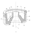
- FIG. 2 is a partial perspective view showing a part of a sealing device according to an embodiment of the present invention.
- 2 is a cross-sectional view showing one cross section along an axis of the sealing device shown in FIG. 1 .
- 3 is a partial cross-sectional view showing a cross section of a seal lip in the sealing device shown in FIG. 2 and its vicinity.
- 13 is a view showing a part of the elastic body portion in a state in which the center of the inner end of the seal lip is offset from the axis of the sealing device.
- FIG. FIG. 4 is a cross-sectional view showing the sealing device in use.
- 6 is a cross-sectional view showing a state in which a guide member is inserted into an internal space of the seal lip.
- FIG. 11 is a view showing a state in which a guide member is inserted into an internal space of a seal lip whose base end center is offset from an axis line;
- FIG. 6 is a partial perspective view showing a part of a sealing device according to a second embodiment of the present invention.
- FIG. 11 is a partial perspective view showing a part of a sealing device according to a modified example of the sealing device according to the second embodiment of the present invention.
- the sealing device is a sealing device for blocking the gap between a first guide member, which is a member for guiding a fluid, and a second guide member, which is a member for guiding a fluid and has an opening for accommodating the first guide member.
- the first guide member is, for example, a pipe line
- the second guide member is, for example, a pipe line or a container having an opening for accommodating the end of another pipe line.
- the fluid is, for example, a coolant used for cooling
- the first guide member and the second guide member are members that form a guide path of a cooling device.
- the cooling device is, for example, a cooling device of an inverter device.
- the sealing device 1 according to the embodiment of the present invention is used to block the gap between the first guide member and the second member, which are members of the cooling device of an inverter device.
- the application of the sealing device according to the present invention is not limited to the cooling device of an inverter device, and may also be used in other devices.
- FIG. 1 is a partial perspective view showing a part of a sealing device 1 according to an embodiment of the present invention, and FIG. 1 shows a part of the sealing device 1 cut along a plane along the axis x.
- FIG. 2 is a cross-sectional view showing one of the cross sections of the sealing device 1 along the axis x, and FIG. 2 shows a cross section of the sealing device 1 on one side of the axis x.
- the sealing device 1 has an elastic body part 2 that is a part formed from an elastic body and has an annular shape around the axis x.
- the elastic body part 2 has a seal lip 10 that is a part having an annular shape around the axis x.
- the seal lip 10 is adapted to come into contact with a first guide member inserted into the seal lip 10.
- the tightening margin ⁇ of the seal lip 10 with respect to the first guide member inserted into the seal lip 10 is set to a size that makes it easy to insert the first guide member into the seal lip 10.
- the seal lip 10 is a cylindrical part extending along the axis x. The configuration of the sealing device 1 will be specifically described below.
- the sealing device 1 has a reinforcing ring 30 for reinforcing the elastic body portion 2.
- the reinforcing ring 30 is a member attached to the elastic body portion 2 so as to cover the elastic body portion 2, and is a member having annular rigidity around the axis x.
- the reinforcing ring 30 is, for example, a metal or resin member.
- the reinforcing ring 30 also has, for example, an annular portion 31 and a tubular portion 32 extending from the annular portion 31.
- the annular portion 31 is, for example, a portion that extends in an annular or approximately annular shape around the axis x, and is a hollow disk-shaped portion with the axis x as its central axis or approximately central axis.
- the tubular portion 32 is a tubular portion extending along the axis x, for example, a cylindrical or approximately cylindrical portion with the axis x as its central axis or approximately central axis. The tubular portion 32 extends from the outer peripheral end of the annular portion 31.
- the cylindrical portion 32 has an outer peripheral surface 32a facing the outer peripheral side, and the cylindrical portion 32 has a shape and a diameter corresponding to the inner peripheral surface of the opening so that the axis x of the sealing device 1 coincides or almost coincides with the axis of the opening of the second guide member in the use state of the sealing device 1, as described later.
- the shape of the cylindrical portion 32 is, for example, cylindrical or almost cylindrical with the axis x as the central axis or almost central axis.
- the tip portion 32b which is the tip side part of the cylindrical portion 32, has a smaller diameter than the outer peripheral surface 32a of the cylindrical portion 32.
- the diameter of the outer peripheral surface 32a of the cylindrical portion 32 is set to a size such that, for example, in the use state in which the sealing device 1 described later is attached to the opening of the second guide member to which the sealing device 1 is applied, the sealing device 1 is pressed against the inner peripheral surface of the opening.
- the sealing device 1 is fixed to the application object by metal-to-metal fitting, and the area between the application object and the sealing device 1 is sealed.
- the step reinforcement ring 30 is integrally formed from the same material, and the annular portion 31 and the tubular portion 32 are parts of the integrally formed reinforcement ring 30.
- the elastic body portion 2 has, for example, a root portion 20 in addition to the seal lip 10.
- the root portion 20 is the portion from which the seal lip 10 protrudes.
- the elastic body portion 2 has, for example, a base portion 21, a cover portion 22, and a gasket portion 23.
- the seal lip 10 forms an internal space S1 extending in the direction of the axis x, and extends parallel to the axis x, for example, as shown in Figures 1 and 2.
- the seal lip 10 extends, for example, in a cylindrical or approximately cylindrical shape with the axis x as the central axis or approximate central axis, and the seal surface 11, which is the inner peripheral surface of the seal lip 10 that defines the internal space S1, is a cylindrical or approximately cylindrical surface with the axis x as the central axis or approximate central axis.
- An opening 13 is formed at the end (inner end 10a) of the inner side (upper side in Figure 2) of the seal lip 10 in the direction of the axis x, and the internal space S1 of the seal lip 10 is released to the outside at the inner end 10a.
- the seal lip 10 is connected to the root portion 20 at its end (root end 10b) on the outer side in the direction of the axis x (lower side in FIG. 2), and the internal space S1 of the seal lip 10 is connected to the internal space S2 of the root portion 20.
- the root portion 20 is an annular portion around the axis x, and extends, for example, in a cylindrical shape along the axis x.
- the root portion 20 is tapered toward the seal lip 10 along the axis x, and has, for example, a conical or substantially conical cylindrical shape with the axis x as the central axis or substantially central axis.
- the inner peripheral surface 20a that defines the internal space S2 of the root portion 20 is smoothly connected to the seal surface 11 of the seal lip 10.
- the inner peripheral surface 20a of the root portion 20 does not have to be smoothly connected to the seal surface 11 of the seal lip 10.
- the thickness of the root portion 20 is greater than the thickness of the seal lip 10.
- the root portion 20 has an annular surface (end surface 20b) facing the inner side at the inner end, and the seal lip 10 protrudes from the end surface 20b.
- the base 21 is an annular portion about the axis x and extends from the outer end of the root portion 20 to the outer periphery.
- the cover portion 22 is an annular portion about the axis x and extends from the outer end of the base 21 to the inner side.
- a gasket portion 23 is provided at the inner end of the cover portion 22, protruding from the cover portion 22 to the outer periphery.
- the gasket portion 23 has a sealing surface 23a that faces the outer periphery, and the sealing surface 23a forms, for example, a cylindrical surface or an approximately cylindrical surface with the axis x as the central axis or approximately the central axis.
- the base 21, cover 22 and gasket 23 of the elastic body 2 are attached to the reinforcing ring 30 so as to cover the reinforcing ring 30.
- the base 21, cover 22 and gasket 23 are bonded to the reinforcing ring 30.
- the base 21 covers the annular portion 31 from the inside so as to cover the inner end (inner end 31a) of the annular portion 31 of the reinforcing ring 30.
- the cover 23 covers the tubular portion 32 of the reinforcing ring 30 from the inner side
- the gasket 23 covers the tip 32b of the tubular portion 32 of the reinforcing ring 30 from the outer side.
- the diameter of the sealing surface 23a of the gasket 23 is set to a size that is pressed against the inner surface of the opening when the sealing device 1 described later is attached to the opening of the second guide member to which it is applied.
- the gasket portion 23 is compressed radially between the tip portion 32b of the cylindrical portion 32 of the reinforcing ring 30 and the opening, fixing the sealing device 1 to the application object and sealing the area between the application object and the sealing device 1.
- the seal lip 10 is located, for example, on the inner circumferential side of the gasket portion 23.
- the inner end 10a of the seal lip 10 is located at the same or approximately the same position as the tip 23b of the gasket portion 23 in the axial x direction, and is not located further inward than the gasket portion 23. Note that the inner end 10a of the seal lip 10 does not have to be located at the same position as the tip 23b of the gasket portion 23 in the axial x direction.
- the inner end 10a of the seal lip 10 may be located further inward than the tip 23b of the gasket portion 23 in the axial x direction, and the inner end 10a of the seal lip 10 may be located further outward than the tip 23b of the gasket portion 23 in the axial x direction.
- FIG. 3 is a partial cross-sectional view showing the vicinity of the cross section of the seal lip 10 shown in FIG. 2.
- a part of the first guide member (guide member 102) housed in the internal space S1 of the seal lip 10 in a use state as described later is shown by a virtual line.
- the radius (radius R) of the seal surface 11 of the seal lip 10 is a predetermined size
- the length L of the seal lip 10 is a predetermined length
- the thickness T of the seal lip 10 is a predetermined thickness.
- the radius R of the seal surface 11 is the distance between the axis x and the seal surface 11 in a direction perpendicular to the axis x (radial direction).
- the length of the seal lip 10 is the width of the seal lip 10 in the axis x direction, and is the distance between the inner end 10a and the root end 10b of the seal lip 10 in the axis x direction.
- the thickness T of the seal lip 10 is the width of the seal lip 10 in the radial direction, and is the distance between the seal surface 11 and the outer circumferential surface 12 of the seal lip 10 in the axis x direction.
- the first guide member (guide member 102) is inserted into the internal space S1 of the seal lip 10, and the seal surface 11 of the seal lip 10 contacts the first guide member to seal the gap between the seal lip 10 and the first guide member.
- the tightening margin ⁇ of the seal lip 10 is set to a value such that the force required to insert the first guide member into the internal space S1 of the seal lip 10 is a predetermined value (insertion force F1).
- the magnitude of this predetermined value of the insertion force F1 can be, for example, various values that make it easy to insert the first guide member into the internal space S1 of the seal lip 10, and can be set to various values.
- the tightening margin ⁇ is set to be smaller than the conventional standard tightening margin, for example.
- the tightening margin ⁇ is the difference between the radius (radius R1) of the outer circumferential surface (outer circumferential surface 102a) of the first guide member (guide member 102) with which the seal surface 11 contacts in the use state and the radius R of the seal surface 11 (see FIG. 3).
- the length L of the seal lip 10 is set in relation to, for example, foreign matter.
- foreign matter may be present between the seal surface 11 of the seal lip 10 and the first guide member.
- Foreign matter may include anything that may be present between the seal surface 11 and the first guide member in the sealing device 1 in use.
- Foreign matter may be, for example, dust, dirt, tiny particles, tiny fibers, etc., that may unintentionally adhere to the first guide member or the seal surface 11 of the seal lip 10 when the first guide member is inserted into the seal lip 10, and may be unintentionally present between the first guide member and the seal surface 11.
- the length L of the seal lip 10 is larger than the size of such foreign matter that may be present between the first guide member and the seal surface 11 in the sealing device 1 in use.
- Such foreign matter includes at least one of spherical foreign matter and fibrous foreign matter.
- the length L of the seal lip 10 is, for example, larger than 1 mm.
- the size (length) of the fibrous foreign matter is, for example, 1 mm
- the length L of the seal lip 10 is, for example, larger than 1 mm.
- the length L of the seal lip 10 is, for example, larger than 2 mm.
- the length L of the seal lip 10 can be various values depending on the usage mode of the sealing device 1.
- the upper limit of the length L of the seal lip 10 can be various values depending on the application target of the sealing device 1 and the usage mode of the sealing device 1.
- the clamping margin ⁇ of the seal lip 10 and the thickness T of the seal lip 10 are set, for example, so that the force required to insert the first guide member into the internal space S1 of the seal lip 10 is a predetermined value (insertion force F2).
- the magnitude of this predetermined value of the insertion force F2 can be set to various values, for example, so that the first guide member can be easily inserted into the internal space S1 of the seal lip 10.
- the clamping margin ⁇ is set smaller than the conventional standard clamping margin
- the thickness T is set smaller than the conventional standard thickness of the seal lip.
- the clamping margin ⁇ of the seal lip 10 and the thickness T of the seal lip 10 are set, for example, so that the force required to insert the first guide member into the internal space S1 of the seal lip 10 is a predetermined value (insertion force F3) when the seal lip 10 is deformed and the center C of the root end 10b of the seal lip 10 is displaced (eccentric) from the axis x (see FIG. 4).
- the magnitude of this predetermined value of the insertion force F3 can be set to various values, for example, so that the first guide member can be easily inserted into the internal space S1 of the seal lip 10 that has been deformed due to eccentricity or other reasons.
- the tightening margin ⁇ is set smaller than the conventional standard tightening margin
- the thickness T is set smaller than the conventional standard thickness of the seal lip.
- the interference ⁇ of the seal lip 10 and the thickness T of the seal lip 10 are set, for example, so that the pressure on the contact surface between the seal lip 10 and the first guide member is a predetermined pressure (pressure P1).
- the magnitude of this predetermined value of pressure P1 can be, for example, various magnitudes such that the sealing between the seal surface 11 of the seal lip 10 and the first guide member inserted into the internal space S1 exhibits a predetermined sealing performance or is assumed to exhibit a predetermined sealing performance, and can be set to various values.
- the interference ⁇ of the seal lip 10 and the thickness T of the seal lip 10 are set, for example, so that the pressure on the contact surface between the seal lip 10 and the first guide member when the seal lip 10 is eccentric (see FIG.
- This predetermined value of pressure P2 can be, for example, various magnitudes such that the sealing between the seal surface 11 of the seal lip 10 and the first guide member inserted into the internal space S1 exhibits a predetermined sealing performance or is assumed to exhibit a predetermined sealing performance, and can be set to various values.
- the elastic body portion 2 is a member integrally formed from the same material, and the seal lip 10, root portion 20, base portion 21, cover portion 22, and gasket portion 23 are integrally formed parts of the elastic body portion 2 and are each integrally connected.
- the elastic body portion 2 is formed from an elastic body, and is integrally molded, for example, by cross-linking and bonding an elastic material to the reinforcing ring 30.
- the elastic body portion 2 is a molded body obtained, for example, by insert molding using the reinforcing ring 30 as an insert part.
- FIG. 5 is a cross-sectional view showing the sealing device 1 in use.
- the first guide member is inserted into the internal space S1 of the seal lip 10, the seal surface 11 of the seal lip 10 contacts the first guide member, and the sealing device 1 is fitted into the opening of the second guide member, the seal surface 23a of the gasket portion 23 and the outer peripheral surface 32a of the cylindrical portion 32 contact the opening, and the sealing device 1 is in use.
- the sealing device 1 is applied to the cooling path 101 of the cooling device 100 of the inverter.
- the first guide member is a guide member 102 that is one of the members constituting the cooling path 101
- the second guide member is a guide member 103 that is one of the members constituting the cooling path 101.
- the cooling path 101 is a guide path that guides the cooling liquid into the inverter
- the guide members 102 and 103 are members that guide the cooling liquid in a part of the cooling path 101, such as a tube or a container.
- the guide member 103 has an opening 104 that receives the end of the guide member 102.
- the guide member 102 is accommodated in the internal space S1 of the seal lip 10, and the seal surface 11 contacts the outer peripheral surface 102a of the guide member 102, sealing the gap between the seal lip 10 and the guide member 102.
- the sealing device 1 is accommodated in the opening 104 of the guide member 103, the outer peripheral surface 32a of the cylindrical portion 32 of the reinforcing ring 30 contacts the inner peripheral surface 104a of the opening 104, and the seal surface 23a of the gasket portion 23 contacts the inner peripheral surface 104a of the opening 104, sealing the gap between the cylindrical portion 32 and the gasket portion 23 and the opening 104.
- the outer peripheral surface 32a of the cylindrical portion 32 of the reinforcing ring 30 has a shape corresponding to the inner peripheral surface 104a of the opening 104 as described above, and in the sealing device 1, the central axis of the opening 104 coincides or approximately coincides with the axis x of the sealing device 1 within the opening 104. In this way, the sealing device 1 closes the gap in the connection area between the guide members 102 and 103, and the guide members 102 and 103 are connected.
- Figure 6 is a cross-sectional view showing the state when the guide member 102 is inserted into the internal space S1 of the seal lip 10.
- the clamping margin ⁇ of the seal lip 10 is set so that the force (insertion force F) required to insert the guide member 102 into the internal space S1 is a predetermined insertion force F1 that makes it easy to insert the guide member 102 into the internal space S1.
- the predetermined insertion force F1 may be a single value or a range.
- the clamping margin ⁇ of the seal lip 10 and the thickness T of the seal lip 10 are set so that the force (insertion force F) required to insert the guide member 102 into the internal space S1 of the seal lip 10 is a predetermined insertion force F2 that makes it easy to insert the guide member 102 into the internal space S1.
- the insertion force F2 is a value that is set taking into consideration not only the clamping margin ⁇ of the seal lip 10 but also the thickness T of the seal lip 10. This allows the insertion force to be reduced, making it easier to insert the guide member 102 into the internal space S1 of the seal lip 10.
- Figure 7 is a diagram showing how a guide member 102 is inserted into the internal space S1 of a seal lip 10 in which the center C of the root end 10b is shifted (eccentric) from the axis x.
- a misalignment may occur between the central axis of the guide member 102 and the central axis (axis x) of the opening 104 of the guide member 103.
- the guide member 102 is inserted into the internal space S1 of the seal lip 10
- the center C of the root end 10b is shifted from the axis x
- the guide member 102 is inserted into this eccentric seal lip 10.
- the interference ⁇ of the seal lip 10 and the thickness T of the seal lip 10 are set so that the force (insertion force F) required to insert the guide member 102 into the internal space S1 of the seal lip 10, whose center C of the root end 10b is offset from the axis x, is a predetermined insertion force F3 that makes it easy to insert the guide member 102 into the internal space S1.
- This makes it easy to insert the guide member 102 into the internal space S1 of the seal lip 10, whose center C of the root end 10b is offset from the axis x.
- the length L of the seal lip 10 is longer than the length in the axial x direction of any foreign matter present between the seal surface 11 of the seal lip 10 and the outer peripheral surface 102a of the guide member 102 when the sealing device 1 is in use. This prevents any foreign matter present between the seal surface 11 and the outer peripheral surface 102a of the guide member 102 from penetrating the contact surface between the seal surface 11 and the outer peripheral surface 102a in the axial x direction. In this way, the seal lip 10 can prevent a decrease in sealing performance against foreign matter even if the pressure at the contact surface between the seal lip 10 and the guide member 102 is low.
- the interference ⁇ of the seal lip 10 and the thickness T of the seal lip 10 are set as described above so that the pressure (contact surface pressure P) at the contact surface between the seal surface 11 of the seal lip 10 and the outer peripheral surface 102a of the guide member 102 in the use state is a pressure P1 of a predetermined magnitude at which the seal lip 10 exhibits a predetermined sealing performance. Therefore, the seal lip 10 exhibits the desired sealing performance in the use state.
- the interference ⁇ of the seal lip 10 and the thickness T of the seal lip 10 are set as described above so that the pressure P at the contact surface between the seal surface 11 of the eccentric seal lip 10 and the outer peripheral surface 102a of the guide member 102 in the use state (see FIG.
- the interference ⁇ and thickness T of the seal lip 10 are set based on the correlation between the eccentricity followability, axial insertability, and contact surface pressure so that the eccentricity followability, axial insertability, and contact surface pressure of the seal lip 10 are good. Therefore, even if the sealing device 1 makes it easy to attach the guide member 102 to the seal lip 10, the sealing performance of the seal lip 10 is not reduced.
- the eccentricity followability is the performance of maintaining the area of the seal surface 10 that contacts the outer peripheral surface 102a of the guide member 102 when the seal lip 10 becomes eccentric.
- the axial insertability is the performance of the seal lip 10 when inserted into the internal space S1 of the guide member 102.
- the sealing device 1 can prevent a decrease in sealing performance while also preventing a decrease in installation performance.
- FIG. 8 is a partial perspective view showing a part of the sealing device 3 according to the second embodiment of the present invention, and FIG. 8 shows a part of the sealing device 3 cut along a plane along the axis x.
- the sealing device 3 differs from the above-mentioned sealing device 1 in that the elastic body portion 2 has a support portion 14 which is a portion for applying tension to the seal lip 10.
- the same reference numerals are used to denote the same configuration or configuration having the same function as the above-mentioned sealing device 1, and a description is omitted, and different configurations will be described.
- the sealing device 3 specifically has ribs 14 as multiple support parts extending along the axis x.
- the ribs 14 are, for example, plate-shaped parts extending along a plane including the axis x.
- the multiple ribs 14 are, for example, provided at equal or approximately equal angular intervals around the axis x.
- the ribs 14 also extend between the outer peripheral surface 20c of the root portion 20, the inner peripheral surface 22a of the cover portion 22, and the inner surface 21a of the base portion 21.
- the outer peripheral surface 20c of the root portion 20 is the surface facing the outer peripheral side of the root portion 20
- the inner peripheral surface 22a of the cover portion 22 is the surface facing the inner peripheral side of the cover portion 22
- the inner surface 21a of the base portion 21 is the surface facing the inner side of the base portion 21.
- the rib 14 supports the root portion 20 from the outer periphery and pushes the root portion 20 in the direction toward the axis x.
- a tension force is generated in the seal lip 10 such that the seal lip 10 follows the guide member 102 that is displaced due to eccentricity or the like in the use state. Therefore, the ability of the seal lip 10 to follow the guide member 102 can be improved.
- the sealing performance of the seal lip 10 can be suppressed from decreasing.
- the sealing device 3 has the above-mentioned action and effect of the sealing device 1.
- FIG. 9 is a partial perspective view showing a part of the sealing device 4 according to a modified example of the sealing device 3 according to the second embodiment of the present invention.
- FIG. 9 shows a part of the sealing device 4 cut along a plane along the axis x.
- the sealing device 4 has a different rib shape from the above-mentioned sealing device 3.
- the rib 15 of the sealing device 4 extends between the outer peripheral surface 12 of the seal lip 10 and the inner peripheral surface 22a of the cover portion 22.
- the rib 15 extends between the outer peripheral surface 12 of the seal lip 10, the outer peripheral surface 20c of the root portion 20, the inner peripheral surface 22a of the cover portion 22, and the inner surface 21a of the base portion 21.
- the rib 15 supports the root portion 20 and the seal lip 10 from the outer periphery and presses the root portion 20 and the seal lip 10 in the direction toward the axis x.
- a tension force is generated in the root portion 20 and the seal lip 10 to make the seal lip 10 follow the guide member 102 that is displaced eccentrically or the like in the use state. Therefore, the followability of the seal lip 10 to the guide member 102 can be improved.
- the sealing performance of the seal lip 10 can be further suppressed from deteriorating.
- the sealing device 4 achieves the same effects as the sealing device 1 described above.
- the above-described embodiments are intended to facilitate understanding of the present invention, and are not intended to limit the present invention. Furthermore, the above-described embodiments do not limit the scope of application of the present invention, and may include anything to which the present invention can be used.
- the components of the above-described embodiments, as well as their arrangement, materials, conditions, shapes, sizes, etc., are not limited to those exemplified, and may be modified as appropriate.
- the present invention includes differences that arise in implementation due to manufacturing tolerances, etc.
- the components shown in different embodiments may be partially substituted or combined to the extent that there is no technical contradiction.
- the configurations may be selectively combined as appropriate to achieve at least some of the above-described problems and effects.
Landscapes
- Engineering & Computer Science (AREA)
- General Engineering & Computer Science (AREA)
- Mechanical Engineering (AREA)
- Physics & Mathematics (AREA)
- Geometry (AREA)
- Gasket Seals (AREA)
Priority Applications (3)
| Application Number | Priority Date | Filing Date | Title |
|---|---|---|---|
| CN202480009199.6A CN120604062A (zh) | 2023-01-25 | 2024-01-18 | 密封装置 |
| EP24747206.1A EP4656911A1 (en) | 2023-01-25 | 2024-01-18 | Sealing device |
| JP2024573013A JPWO2024157877A1 (https=) | 2023-01-25 | 2024-01-18 |
Applications Claiming Priority (2)
| Application Number | Priority Date | Filing Date | Title |
|---|---|---|---|
| JP2023-009542 | 2023-01-25 | ||
| JP2023009542 | 2023-01-25 |
Publications (1)
| Publication Number | Publication Date |
|---|---|
| WO2024157877A1 true WO2024157877A1 (ja) | 2024-08-02 |
Family
ID=91970577
Family Applications (1)
| Application Number | Title | Priority Date | Filing Date |
|---|---|---|---|
| PCT/JP2024/001352 Ceased WO2024157877A1 (ja) | 2023-01-25 | 2024-01-18 | 密封装置 |
Country Status (4)
| Country | Link |
|---|---|
| EP (1) | EP4656911A1 (https=) |
| JP (1) | JPWO2024157877A1 (https=) |
| CN (1) | CN120604062A (https=) |
| WO (1) | WO2024157877A1 (https=) |
Citations (6)
| Publication number | Priority date | Publication date | Assignee | Title |
|---|---|---|---|---|
| JPH09324883A (ja) * | 1996-04-05 | 1997-12-16 | Noriatsu Kojima | 管接続用パッキンおよびその装着方法および該方法に用いる装着治具 |
| JP2004068889A (ja) * | 2002-08-05 | 2004-03-04 | Nok Corp | 密封装置 |
| WO2011158750A1 (ja) * | 2010-06-15 | 2011-12-22 | 内山工業株式会社 | 環状弾性ガスケット |
| JP2012516424A (ja) * | 2009-01-28 | 2012-07-19 | フェデラル−モーグル コーポレイション | ラジアルシャフトシール、ラジアルシャフトシールアセンブリおよび設置方法 |
| JP2020013830A (ja) | 2018-07-13 | 2020-01-23 | トヨタ自動車株式会社 | 電力変換装置 |
| JP2022052395A (ja) * | 2020-09-23 | 2022-04-04 | Nok株式会社 | 密封装置 |
Family Cites Families (2)
| Publication number | Priority date | Publication date | Assignee | Title |
|---|---|---|---|---|
| JPS50140752A (https=) * | 1974-04-21 | 1975-11-12 | ||
| FR2554205B1 (fr) * | 1983-10-28 | 1986-06-13 | Pont A Mousson | Garniture d'etancheite pour joints de tuyaux en fonte |
-
2024
- 2024-01-18 JP JP2024573013A patent/JPWO2024157877A1/ja active Pending
- 2024-01-18 EP EP24747206.1A patent/EP4656911A1/en active Pending
- 2024-01-18 WO PCT/JP2024/001352 patent/WO2024157877A1/ja not_active Ceased
- 2024-01-18 CN CN202480009199.6A patent/CN120604062A/zh active Pending
Patent Citations (6)
| Publication number | Priority date | Publication date | Assignee | Title |
|---|---|---|---|---|
| JPH09324883A (ja) * | 1996-04-05 | 1997-12-16 | Noriatsu Kojima | 管接続用パッキンおよびその装着方法および該方法に用いる装着治具 |
| JP2004068889A (ja) * | 2002-08-05 | 2004-03-04 | Nok Corp | 密封装置 |
| JP2012516424A (ja) * | 2009-01-28 | 2012-07-19 | フェデラル−モーグル コーポレイション | ラジアルシャフトシール、ラジアルシャフトシールアセンブリおよび設置方法 |
| WO2011158750A1 (ja) * | 2010-06-15 | 2011-12-22 | 内山工業株式会社 | 環状弾性ガスケット |
| JP2020013830A (ja) | 2018-07-13 | 2020-01-23 | トヨタ自動車株式会社 | 電力変換装置 |
| JP2022052395A (ja) * | 2020-09-23 | 2022-04-04 | Nok株式会社 | 密封装置 |
Non-Patent Citations (1)
| Title |
|---|
| See also references of EP4656911A1 |
Also Published As
| Publication number | Publication date |
|---|---|
| EP4656911A1 (en) | 2025-12-03 |
| CN120604062A (zh) | 2025-09-05 |
| JPWO2024157877A1 (https=) | 2024-08-02 |
Similar Documents
| Publication | Publication Date | Title |
|---|---|---|
| CN110894900B (zh) | 垫圈 | |
| EP3412941B1 (en) | Gasket | |
| JP5692504B2 (ja) | ガスケット | |
| CN101802465B (zh) | 唇式密封件的安装构造 | |
| US20110241341A1 (en) | Exhaust pipe for a motor vehicle and exhaust system | |
| WO2022151760A1 (zh) | 一种控制阀 | |
| WO2010084853A1 (ja) | シールリング | |
| US20020094875A1 (en) | Attachment structure for joint boot | |
| JP3177086B2 (ja) | 密封装置 | |
| WO2012124534A1 (ja) | 密封装置 | |
| CA2745120A1 (en) | Flow machine | |
| CN101772664A (zh) | 密封装置 | |
| JP4396790B2 (ja) | オイルシール | |
| US11408509B2 (en) | Sealing plug | |
| US10408334B2 (en) | Attachment structure for oil guide plate | |
| WO2008013281A1 (en) | Seal ring | |
| WO2024157877A1 (ja) | 密封装置 | |
| JP7181581B2 (ja) | 配管接続構造及び接続部材 | |
| US11313469B2 (en) | Sealing structure | |
| JP7181582B2 (ja) | 配管接続構造及び接続部材 | |
| JPH11236985A (ja) | 配管の接続構造 | |
| JP2005098391A (ja) | アキュムレータおよびアキュムレータ用スペーサー | |
| JPH0810713Y2 (ja) | 密封装置 | |
| US20240344590A1 (en) | Torsional Vibration Damper | |
| JPS61167779A (ja) | ロータリシヤフトリツプシール |
Legal Events
| Date | Code | Title | Description |
|---|---|---|---|
| 121 | Ep: the epo has been informed by wipo that ep was designated in this application |
Ref document number: 24747206 Country of ref document: EP Kind code of ref document: A1 |
|
| ENP | Entry into the national phase |
Ref document number: 2024573013 Country of ref document: JP Kind code of ref document: A |
|
| WWE | Wipo information: entry into national phase |
Ref document number: 2024573013 Country of ref document: JP |
|
| WWE | Wipo information: entry into national phase |
Ref document number: 202480009199.6 Country of ref document: CN |
|
| NENP | Non-entry into the national phase |
Ref country code: DE |
|
| WWP | Wipo information: published in national office |
Ref document number: 202480009199.6 Country of ref document: CN |
|
| WWP | Wipo information: published in national office |
Ref document number: 2024747206 Country of ref document: EP |