WO2024157604A1 - 飲料供給装置 - Google Patents
飲料供給装置 Download PDFInfo
- Publication number
- WO2024157604A1 WO2024157604A1 PCT/JP2023/043094 JP2023043094W WO2024157604A1 WO 2024157604 A1 WO2024157604 A1 WO 2024157604A1 JP 2023043094 W JP2023043094 W JP 2023043094W WO 2024157604 A1 WO2024157604 A1 WO 2024157604A1
- Authority
- WO
- WIPO (PCT)
- Prior art keywords
- milk
- steam
- pump
- pipe
- gear pump
- Prior art date
- Legal status (The legal status is an assumption and is not a legal conclusion. Google has not performed a legal analysis and makes no representation as to the accuracy of the status listed.)
- Ceased
Links
Images






Classifications
-
- A—HUMAN NECESSITIES
- A47—FURNITURE; DOMESTIC ARTICLES OR APPLIANCES; COFFEE MILLS; SPICE MILLS; SUCTION CLEANERS IN GENERAL
- A47J—KITCHEN EQUIPMENT; COFFEE MILLS; SPICE MILLS; APPARATUS FOR MAKING BEVERAGES
- A47J31/00—Apparatus for making beverages
- A47J31/44—Parts or details or accessories of beverage-making apparatus
-
- B—PERFORMING OPERATIONS; TRANSPORTING
- B67—OPENING, CLOSING OR CLEANING BOTTLES, JARS OR SIMILAR CONTAINERS; LIQUID HANDLING
- B67D—DISPENSING, DELIVERING OR TRANSFERRING LIQUIDS, NOT OTHERWISE PROVIDED FOR
- B67D1/00—Apparatus or devices for dispensing beverages on draught
- B67D1/08—Details
Definitions
- the present invention relates to a beverage supply device.
- Patent Document 1 proposes a beverage supplying device that supplies milk to a container as foamed milk.
- a gear pump is used to suck milk from a milk tank, and the sucked milk is compressed with pressurized air (air sent out by an air pump) and sent to an expansion section to generate foamed milk and supply it to the container.
- the present invention aims to provide a beverage supply device that can reduce manufacturing costs.
- the beverage supplying device of the present invention is a beverage supplying device that supplies beverage ingredients stored in an ingredient tank to a container through a nozzle, and is characterized by comprising: a first pump that sucks the beverage ingredients from the ingredient tank and delivers them to a mixing section; air delivery means that generates and delivers pressurized air to the mixing section; and a second pump that, when the beverage ingredients and the pressurized air are delivered to the mixing section, compresses the beverage ingredients and the pressurized air and delivers them to an orifice section to generate foamed beverage ingredients and supply them to the container through the nozzle, while, when the beverage ingredients are delivered to the mixing section, compresses the beverage ingredients and delivers them to the orifice section and supplies them to the container through the nozzle.
- the present invention is also characterized in that, in the beverage supply device, a steam delivery means is provided for generating and delivering heating steam to the mixing section, and when the beverage ingredients, the pressurized air and the heating steam are delivered to the mixing section, the second pump compresses the beverage ingredients, the pressurized air and the heating steam and delivers them to the orifice section to generate heated, foamy beverage ingredients and deliver them to the container through the nozzle, while when the beverage ingredients and the heating steam are delivered to the mixing section, the second pump compresses the beverage ingredients and the heating steam and delivers them to the orifice section to generate heated beverage ingredients and deliver them to the container through the nozzle.
- the present invention is also characterized in that the beverage supply device includes a control unit that drives the second pump and allows the steam delivery means to deliver the heating steam before driving the first pump, and circulates the heating steam through the orifice portion to preheat the orifice portion.
- the present invention also provides the beverage supply device, which includes a steam tank constituting the steam delivery means and generating the heating steam, a blow steam pipe connecting the flow pipe of the beverage ingredients sucked by the first pump, and a blow steam supply valve that restricts the flow of blow steam through the blow steam pipe when in a closed state, and allows the flow of blow steam through the blow steam pipe when in an open state, and the control unit opens the blow steam supply valve on the condition that the first pump is stopped while the second pump is operating.
- a steam tank constituting the steam delivery means and generating the heating steam
- a blow steam pipe connecting the flow pipe of the beverage ingredients sucked by the first pump
- a blow steam supply valve that restricts the flow of blow steam through the blow steam pipe when in a closed state, and allows the flow of blow steam through the blow steam pipe when in an open state
- the control unit opens the blow steam supply valve on the condition that the first pump is stopped while the second pump is operating.
- the present invention also provides a beverage supply device comprising a steam tank that constitutes the steam delivery means and generates the heating steam, a hot water pipe that connects the beverage ingredient distribution pipe drawn by the first pump, and a hot water supply valve that restricts hot water from flowing through the hot water pipe when in a closed state, but allows hot water to flow through the hot water pipe when in an open state, and the control unit opens the hot water supply valve on the condition that the first pump is stopped while the second pump is operating.
- the present invention is also characterized in that in the beverage supply device, the beverage ingredient is milk.
- the present invention is also characterized in that in the beverage supply device, the first pump and the second pump are gear pumps.
- the first pump sucks beverage ingredients from the ingredient tank and delivers them to the mixing section
- the air delivery means generates and delivers pressurized air to the mixing section
- the second pump compresses the beverage ingredients and the pressurized air and delivers them to the orifice section to generate foamy beverage ingredients and supply them to the container through the nozzle, while when the beverage ingredients are delivered to the mixing section, the beverage ingredients are compressed and delivered to the orifice section to supply them to the container through the nozzle.
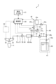
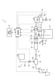
- FIG. 1 is a schematic diagram showing a schematic circuit configuration of a beverage supply device according to a first embodiment of the present invention.
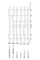
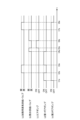
- FIG. 2 is a time chart for explaining the supplying operation of ice milk.
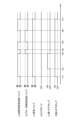
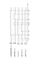
- FIG. 3 is a time chart for explaining the supply operation of ice foamed milk.
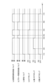
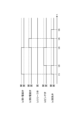
- FIG. 4 is a time chart for explaining the hot milk supply operation.
- FIG. 5 is a time chart for explaining the supplying operation of hot foamed milk.
- FIG. 6 is a schematic diagram showing a schematic circuit configuration of a beverage supplying device according to a second embodiment of the present invention.
- FIG. 7 is a time chart for explaining the ice milk supply operation.
- FIG. 8 is a time chart for explaining the supply operation of ice foamed milk.
- FIG. 1 is a schematic diagram showing a schematic circuit configuration of a beverage supply device according to a first embodiment of the present invention.
- FIG. 2 is a time chart for explaining the supplying operation of ice milk.
- FIG. 3 is a
- FIG. 9 is a time chart for explaining the hot milk supply operation.
- FIG. 10 is a time chart for explaining the supplying operation of hot foamed milk.
- FIG. 11 is a schematic diagram showing a schematic circuit configuration of a beverage supplying device according to another embodiment different from the first and second embodiments.
- FIG. 12 is a time chart for explaining the ice milk supply operation.
- FIG. 13 is a time chart for explaining the supply operation of ice foamed milk.
- FIG. 14 is a time chart for explaining the hot milk supply operation.
- FIG. 15 is a time chart for explaining the supplying operation of hot foamed milk.
- ⁇ First embodiment> 1 is a schematic diagram showing a schematic configuration circuit of a beverage supplying device according to a first embodiment of the present invention.
- the beverage supplying device 1 shown in this example supplies milk for milk-containing coffee such as a caffe latte to a cup C, which is a container.
- This beverage supply device 1 is configured with a milk tank (ingredient tank) 10, a first gear pump (first pump) 13, a steam delivery section (steam delivery means) 16, an air delivery section (air delivery means) 18, a mixing section 19, a second gear pump (second pump) 21, a milk nozzle 23, and a control section 30.
- the milk tank 10 stores milk, which is a beverage ingredient. This milk tank 10 is placed in a cooling container 11, and refrigerates the milk to a specified temperature.
- the first gear pump 13 is connected to the milk tank 10 through the raw material suction line 12, and is connected to the mixing section 19 through the raw material delivery line 14.
- a drive section such as a motor is driven in response to a command given by the control section 30
- the first gear pump 13 sucks milk from the milk tank 10 through the raw material suction line 12 and delivers the milk to the mixing section 19 through the raw material delivery line 14.
- the ingredient suction pipeline 12 is a pipeline formed by connecting multiple pipes, and a first check valve 12a is provided along the way.
- the first check valve 12a allows the flow of fluid (milk) from the milk tank 10, while restricting the flow of fluid toward the milk tank 10.
- This ingredient suction pipeline 12 constitutes the "beverage ingredient flow pipeline" of the present invention.
- the raw material delivery pipeline 14 is a pipeline formed by connecting multiple pipes, and an exhaust pipeline 15 and a second check valve 14a are provided in the middle of the pipeline.
- the exhaust pipeline 15 is provided in a manner that branches off from the middle of the raw material delivery pipeline 14.
- the exhaust pipeline 15 is a pipeline formed by connecting multiple pipes, and an exhaust valve 15a is provided in the middle of the pipeline.
- the exhaust valve 15a is a valve body that opens and closes in response to commands given from the control unit 30. When the exhaust valve 15a is in an open state, it allows fluid (air) to flow through the exhaust pipe 15, but when it is in a closed state, it restricts the flow of fluid through the exhaust pipe 15.
- the second check valve 14a is provided downstream of the exhaust pipe 15 in the raw material delivery pipe 14. This second check valve 14a allows the fluid (milk) to flow toward the mixing section 19, while restricting the flow of fluid from the mixing section 19.
- the steam delivery section 16 is equipped with a steam tank 16a.
- the steam tank 16a is a tank that heats the supplied water and generates steam from the hot water.
- This steam tank 16a is connected to the mixing section 19 through a heating steam pipe 16b, and is connected to the middle of the raw material suction pipe 12 through a blowing steam pipe 17.
- the heating steam pipeline 16b is a pipeline consisting of multiple connected pipes, and a heating steam supply valve 16c and a third check valve 16d are provided along the pipeline.
- the heating steam supply valve 16c is a valve body that opens and closes in response to commands given from the control unit 30. When the heating steam supply valve 16c is in an open state, it allows a fluid (heating steam) to flow through the heating steam pipe 16b, but when the heating steam supply valve 16c is in a closed state, it restricts the flow of fluid through the heating steam pipe 16b.
- the third check valve 16d is provided downstream of the heating steam supply valve 16c in the heating steam pipeline 16b. This third check valve 16d allows the flow of fluid (heating steam, etc.) toward the mixing section 19, while restricting the flow of fluid from the mixing section 19.
- the blow steam pipeline 17 is a pipeline consisting of multiple connected pipes, with one end connected to the steam tank 16a and the other end connected to the raw material suction pipeline 12 between the first check valve 12a and the first gear pump 13.
- the blow steam pipeline 17 is provided with a blow steam supply valve 17a and a fourth check valve 17b along the way.
- the blow steam supply valve 17a is a valve body that opens and closes in response to commands given from the control unit 30. When the blow steam supply valve 17a is in the open state, it allows a fluid (blow steam) to flow through the blow steam pipe 17, but when the blow steam supply valve 17a is in the closed state, it restricts the flow of fluid through the blow steam pipe 17.
- the fourth check valve 17b is provided downstream of the blow steam supply valve 17a in the blow steam line 17. This fourth check valve 17b allows the flow of fluid (blow steam) from the steam tank 16a, but restricts the flow of fluid toward the steam tank 16a.
- the air delivery unit 18 is equipped with an air pump 18a.
- the air pump 18a is connected to the middle of the heating steam pipe 16b through a pressurized air pipe 18b. This air pump 18a generates pressurized air when a drive unit such as a motor operates in response to a command given by the control unit 30.
- the pressurized air pipeline 18b is a pipeline formed by connecting multiple pipes, with one end connected to the air pump 18a and the other end connected to the heating steam pipeline 16b between the heating steam supply valve 16c and the third check valve 16d.
- This type of air delivery section 18 generates pressurized air using the air pump 18a and delivers it to the mixing section 19.
- the mixing section 19 is a container with an internal space for mixing.
- the second gear pump 21 is connected to the mixing section 19 through an inlet pipe 20, and is connected to the milk nozzle 23 through an outlet pipe 22.
- a drive section such as a motor
- the second gear pump 21 compresses the fluid such as the mixture that flows in from the mixing section 19 through the inlet pipe 20, and sends it out to the milk nozzle 23 through the outlet pipe 22.
- the inlet pipeline 20 is a pipeline formed by connecting multiple pipes.
- the outlet pipeline 22 is a pipeline formed by connecting multiple pipes, and an orifice section 22a is provided midway through the pipeline.
- the orifice section 22a is a section whose passage inner diameter is smaller than the passage inner diameter of the outlet pipeline 22.
- the passage inner diameter of the orifice section 22a is, for example, about 1 to 2 mm.
- the milk nozzle 23 discharges milk delivered to it into a cup C placed on a stage (not shown). Although not shown in the figure, the milk nozzle 23 has a built-in shutter mechanism, which allows the milk delivered to it to be discharged into the cup C, or to be discharged into a discharge path without being discharged into the cup C.
- the control unit 30 comprehensively controls the operation of the beverage supply device 1 in accordance with programs and data stored in a memory unit (not shown).
- the control unit 30 may be realized, for example, by having a processing device such as a CPU (Central Processing Unit) execute a program, i.e., by software, or by hardware such as an IC (Integrated Circuit), or by a combination of software and hardware.
- a processing device such as a CPU (Central Processing Unit) execute a program, i.e., by software, or by hardware such as an IC (Integrated Circuit), or by a combination of software and hardware.
- control unit 30 is electrically connected to an operation input unit 31 and an extraction unit 32.
- the operation input unit 31 is used to input operations such as product selection.
- the extraction unit 32 extracts coffee and sends it to the coffee nozzle 33.
- beverage dispenser 1 configured as above dispenses ice milk, ice foamed milk, hot milk, and hot foamed milk.
- FIG. 2 is a time chart to explain the operation of supplying ice milk.
- the heating steam supply valve 16c is closed, the blowing steam supply valve 17a is closed, the exhaust valve 15a is open, the air pump 18a, the first gear pump 13 and the second gear pump 21 are not driven, and a cup C is placed on the stage.
- the milk nozzle 23 is in a state where it discharges the fluid sent to it by the shutter mechanism into the discharge path.
- the control unit 30 opens the heating steam supply valve 16c and closes the exhaust valve 15a, and drives the second gear pump 21. This causes the heating steam generated in the steam tank 16a to flow through the heating steam pipe 16b, the mixing unit 19, the inlet pipe 20, the second gear pump 21, the outlet pipe 22, and the milk nozzle 23 in that order, and then to be discharged into the exhaust path, which can be sterilized.
- the control unit 30 closes the heating steam supply valve 16c and drives the first gear pump 13.
- This first gear pump 13 is driven at a variable voltage.
- the control unit 30 also drives the second gear pump 21 at a low voltage and drives the shutter mechanism of the milk nozzle 23 so that the fluid delivered to it can be discharged into the cup C.
- the first gear pump 13 sucks up milk from the milk tank 10 and delivers it to the mixing unit 19, and the second gear pump 21 compresses the milk delivered to the mixing unit 19 and delivers it to the orifice unit 22a, and the ice milk is discharged and supplied from the milk nozzle 23 into the cup C.
- the control unit 30 stops the first gear pump 13 and opens the blow steam supply valve 17a. This allows the steam (blow steam) generated in the steam tank 16a to flow through the blow steam pipe 17, the raw material suction pipe 12, the first gear pump 13, the raw material delivery pipe 14, and the mixing unit 19 in that order, and milk remaining in the path can be delivered to the mixing unit 19.
- the control unit 30 closes the blow steam supply valve 17a and drives the air pump 18a. This allows the pressurized air generated by the air pump 18a to be sent to the mixing unit 19, and the second gear pump 21, which is in operation, sends the milk remaining in the path after the mixing unit 19 to the milk nozzle 23, where it can be ejected and supplied into the cup C.
- the control unit 30 stops the air pump 18a and opens the blow steam supply valve 17a.
- the control unit 30 also drives the shutter mechanism so that the milk nozzle 23 discharges the fluid sent to it through the discharge path. This allows the blow steam to circulate through the blow steam pipe 17, raw material suction pipe 12, first gear pump 13, raw material delivery pipe 14, and mixing unit 19 in that order, cleaning these paths while performing a sterilization process.
- the control unit 30 closes the blow steam supply valve 17a and opens the heating steam supply valve 16c. This causes the heating steam to flow through the heating steam pipe 16b, the mixing unit 19, the inlet pipe 20, the second gear pump 21, the outlet pipe 22, and the milk nozzle 23 in that order, and then to be discharged into the discharge path, thereby cleaning these paths while performing a sterilization process.
- control unit 30 closes the heating steam supply valve 16c and stops the second gear pump 21, thus ending the supply of ice milk.
- the control unit 30 also opens the exhaust valve 15a to prevent negative pressure from building up in the pathway.
- Figure 3 is a time chart to explain the supply operation of ice foamed milk.
- the heating steam supply valve 16c is closed
- the blowing steam supply valve 17a is closed
- the exhaust valve 15a is open
- the air pump 18a the first gear pump 13 and the second gear pump 21 are not driven
- a cup C is placed on the stage.
- the milk nozzle 23 is in a state where it discharges the fluid sent to it by the shutter mechanism into the discharge path.
- the control unit 30 opens the heating steam supply valve 16c and closes the exhaust valve 15a, and drives the air pump 18a and the second gear pump 21. This allows the heating steam generated in the steam tank 16a to flow through the heating steam pipe 16b, the mixing unit 19, the inlet pipe 20, the second gear pump 21, the outlet pipe 22, and the milk nozzle 23 in that order, and then to be discharged into the exhaust path, which can be sterilized.
- the control unit 30 closes the heating steam supply valve 16c and drives the first gear pump 13.
- the first gear pump 13, the air pump 18a, and the second gear pump 21 are driven with variable voltage.
- the control unit 30 also drives the shutter mechanism of the milk nozzle 23 so that the fluid delivered to it can be discharged into the cup C.
- the first gear pump 13 sucks milk from the milk tank 10 and delivers it to the mixing unit 19, and delivers the pressurized air generated by the air pump 18a to the mixing unit 19, mixing the milk and the pressurized air.
- the second gear pump 21 compresses the milk and pressurized air delivered to the mixing unit 19 and delivers them to the orifice unit 22a to generate foamed milk, and the ice foamed milk is discharged and supplied from the milk nozzle 23 to the cup C.
- the control unit 30 stops the first gear pump 13 and opens the blow steam supply valve 17a. This allows the steam (blow steam) generated in the steam tank 16a to flow through the blow steam pipe 17, the raw material suction pipe 12, the first gear pump 13, the raw material delivery pipe 14, and the mixing unit 19 in that order, and milk remaining in the path can be delivered to the mixing unit 19.
- the air pump 18a since the air pump 18a is driven, the pressurized air generated by the air pump 18a can be delivered to the mixing unit 19, and the second gear pump 21, which is being driven, delivers milk remaining in the path after the mixing unit 19 to the milk nozzle 23, and it can be ejected and supplied through the milk nozzle 23 into the cup C.
- the control unit 30 closes the blow steam supply valve 17a, and at a later time t5b, the control unit 30 stops the air pump 18a and opens the blow steam supply valve 17a.
- the control unit 30 also drives the shutter mechanism so that the milk nozzle 23 discharges the fluid delivered to it through the discharge path. This allows the blow steam to circulate through the blow steam pipe 17, raw material suction pipe 12, first gear pump 13, raw material delivery pipe 14, and mixing unit 19 in that order, cleaning these paths while performing sterilization processing.
- the control unit 30 closes the blow steam supply valve 17a and opens the heating steam supply valve 16c. This allows the heating steam to flow through the heating steam pipe 16b, the mixing unit 19, the inlet pipe 20, the second gear pump 21, the outlet pipe 22, and the milk nozzle 23 in that order, and then be discharged into the discharge path, thereby cleaning these paths while performing a sterilization process.
- control unit 30 closes the heating steam supply valve 16c and stops the second gear pump 21, thereby terminating the supply of iced foamed milk.
- the control unit 30 also opens the exhaust valve 15a to prevent negative pressure from building up in the pathway.
- Figure 4 is a time chart for explaining the hot milk supply operation.
- the heating steam supply valve 16c is closed
- the blowing steam supply valve 17a is closed
- the exhaust valve 15a is open
- the air pump 18a the first gear pump 13 and the second gear pump 21 are not driven
- a cup C is placed on the stage.
- the milk nozzle 23 is in a state where it discharges the fluid sent to it by the shutter mechanism into the discharge path.
- the control unit 30 opens the heating steam supply valve 16c and closes the exhaust valve 15a, and drives the second gear pump 21. This allows the heating steam generated in the steam tank 16a to flow through the heating steam pipe 16b, the mixing unit 19, the inlet pipe 20, the second gear pump 21, the outlet pipe 22, and the milk nozzle 23 in that order, and then be discharged into the exhaust path, thereby sterilizing these paths.
- the orifice unit 22a can be preheated.
- the control unit 30 drives the first gear pump 13.
- This first gear pump 13 is driven at a variable voltage.
- the control unit 30 also drives the second gear pump 21 at a low voltage, and drives the shutter mechanism of the milk nozzle 23 so that the fluid delivered to it can be discharged into the cup C.
- the first gear pump 13 sucks milk from the milk tank 10 and delivers it to the mixing unit 19, and delivers heating steam generated in the steam tank 16a to the mixing unit 19 to heat the milk.
- the second gear pump 21 compresses the milk delivered to the mixing unit 19, i.e., the heated milk, and delivers it to the orifice unit 22a, and the hot milk is discharged and supplied from the milk nozzle 23 into the cup C.
- the control unit 30 stops the first gear pump 13, closes the heating steam supply valve 16c, and opens the blowing steam supply valve 17a. This allows the steam (blow steam) generated in the steam tank 16a to circulate through the blowing steam pipe 17, the raw material suction pipe 12, the first gear pump 13, the raw material delivery pipe 14, and the mixing unit 19 in that order, and milk remaining in the path can be delivered to the mixing unit 19.
- the control unit 30 closes the blow steam supply valve 17a and opens the heating steam supply valve 16c. This allows the heating steam to be sent to the mixing unit 19, and the second gear pump 21, which is in operation, sends the milk remaining in the path after the mixing unit 19 to the milk nozzle 23, where it can be ejected and supplied into the cup C.
- the control unit 30 closes the heating steam supply valve 16c and opens the blowing steam supply valve 17a.
- the control unit 30 also drives the shutter mechanism so that the milk nozzle 23 discharges the fluid sent to it into the discharge path. This allows the blowing steam to circulate through the blowing steam pipe 17, raw material suction pipe 12, first gear pump 13, raw material delivery pipe 14, and mixing unit 19 in that order, cleaning these paths while performing a sterilization process.
- the control unit 30 closes the blow steam supply valve 17a and opens the heating steam supply valve 16c. This allows the heating steam to flow through the heating steam pipe 16b, the mixing unit 19, the inlet pipe 20, the second gear pump 21, the outlet pipe 22, and the milk nozzle 23 in that order, and then be discharged into the discharge path, thereby cleaning these paths while performing a sterilization process.
- control unit 30 closes the heating steam supply valve 16c and stops the second gear pump 21, thereby terminating the supply of hot milk.
- the control unit 30 also opens the exhaust valve 15a to prevent negative pressure from building up in the pathway.
- FIG. 5 is a time chart to explain the supply operation of hot foamed milk.
- the heating steam supply valve 16c is closed
- the blowing steam supply valve 17a is closed
- the exhaust valve 15a is open
- the air pump 18a the first gear pump 13 and the second gear pump 21 are not driven
- a cup C is placed on the stage.
- the milk nozzle 23 is in a state where it discharges the fluid sent to it by the shutter mechanism into the discharge path.
- the control unit 30 opens the heating steam supply valve 16c and closes the exhaust valve 15a, and drives the air pump 18a and the second gear pump 21. This allows the heating steam generated in the steam tank 16a to flow through the heating steam pipe 16b, the mixing unit 19, the inlet pipe 20, the second gear pump 21, the outlet pipe 22, and the milk nozzle 23 in that order, and then be discharged into the exhaust path, thereby sterilizing these paths.
- the orifice unit 22a can be preheated.
- the control unit 30 drives the first gear pump 13.
- the first gear pump 13, the air pump 18a, and the second gear pump 21 are driven with variable voltage.
- the control unit 30 also drives the shutter mechanism of the milk nozzle 23 so that the fluid sent to it can be discharged into the cup C.
- the first gear pump 13 sucks milk from the milk tank 10 and sends it to the mixing unit 19, sends heating steam generated in the steam tank 16a to the mixing unit 19, and sends pressurized air generated by the air pump 18a to the mixing unit 19, heating the milk and mixing it with the pressurized air.
- the second gear pump 21 compresses the heated milk and pressurized air sent to the mixing unit 19 and sends them to the orifice unit 22a to generate foamed milk, and the hot foamed milk is discharged and supplied from the milk nozzle 23 to the cup C.
- the control unit 30 stops the first gear pump 13, closes the heating steam supply valve 16c, and opens the blow steam supply valve 17a. This allows the steam (blow steam) generated in the steam tank 16a to flow through the blow steam pipe 17, the raw material suction pipe 12, the first gear pump 13, the raw material delivery pipe 14, and the mixing unit 19 in that order, and milk remaining in the path can be delivered to the mixing unit 19.
- the air pump 18a since the air pump 18a is driven, the pressurized air generated by the air pump 18a can be delivered to the mixing unit 19, and the second gear pump 21, which is being driven, delivers milk remaining in the path after the mixing unit 19 to the milk nozzle 23, and can be discharged and supplied through the milk nozzle 23 into the cup C.
- the control unit 30 closes the blow steam supply valve 17a and opens the heating steam supply valve 16c. This allows the heating steam to be sent to the mixing unit 19, and the second gear pump 21, which is in operation, sends the milk remaining in the path after the mixing unit 19 to the milk nozzle 23, through which it can be ejected and supplied into the cup C.
- the control unit 30 closes the heating steam supply valve 16c, opens the blowing steam supply valve 17a, and stops driving the air pump 18a.
- the control unit 30 also drives the shutter mechanism so that the milk nozzle 23 discharges the fluid delivered to it through the discharge path. This allows the blowing steam to circulate through the blowing steam pipe 17, raw material suction pipe 12, first gear pump 13, raw material delivery pipe 14, and mixing unit 19 in that order, cleaning these paths while performing sterilization processing.
- the control unit 30 closes the blow steam supply valve 17a and opens the heating steam supply valve 16c. This allows the heating steam to flow through the heating steam pipe 16b, the mixing unit 19, the inlet pipe 20, the second gear pump 21, the outlet pipe 22, and the milk nozzle 23 in that order, and then be discharged into the discharge path, thereby cleaning these paths while performing a sterilization process.
- control unit 30 closes the heating steam supply valve 16c and stops the operation of the second gear pump 21, thereby terminating the supply of hot foamed milk.
- the control unit 30 also opens the exhaust valve 15a to prevent negative pressure from building up in the pathway.
- the first gear pump 13 sucks milk from the milk tank 10 and sends it to the mixing section 19, and the second gear pump 21 compresses the milk sent to the mixing section 19 together with pressurized air or heating steam as necessary and sends it to the orifice section 22a to generate milk in the desired form and supply it to the cup C. Therefore, there is no need for expensive gear pumps that perform sucking and compression as in the past, and the first gear pump 13 and the second gear pump 21 can be general-purpose products, which allows for reduced manufacturing costs.
- the range of adjustment for the form of the milk supplied can be expanded by appropriately changing the drive rotation speeds of the first gear pump 13 and the second gear pump 21.
- control unit 30 drives the second gear pump 21 and allows the delivery of heating steam, which causes the heating steam to flow through the orifice portion 22a to preheat the orifice portion 22a, so that the milk that subsequently passes through the orifice portion 22a can be foamed well.
- the control unit 30 opens the blow steam supply valve 17a on the condition that the first gear pump 13 is stopped and the second gear pump 21 is driven, so that the sterilization process can be performed while cleaning the inside of the pathway including the first gear pump 13.
- ⁇ Embodiment 2> 6 is a schematic diagram showing a schematic circuit configuration of a beverage supplying device according to a second embodiment of the present invention.
- the beverage supplying device 2 shown in this example supplies milk for milk-containing coffee such as caffe latte to a cup C, which is a container.
- This beverage supply device 2 is configured with a milk tank (ingredient tank) 40, a first gear pump (first pump) 43, a steam delivery section (steam delivery means) 45, an air delivery section (air delivery means) 47, a mixing section 48, a second gear pump (second pump) 50, a milk nozzle 52, and a control section 60.
- the milk tank 40 stores milk, which is a beverage ingredient. This milk tank 40 is placed in a cooling container 41, and refrigerates the milk to a specified temperature.
- the first gear pump 43 is connected to the milk tank 40 through the raw material suction line 42, and is connected to the mixing section 48 through the raw material delivery line 44.
- a drive section such as a motor
- the first gear pump 43 sucks milk from the milk tank 40 through the raw material suction line 42 and delivers milk to the mixing section 48 through the raw material delivery line 44.
- the ingredient suction pipeline 42 is a pipeline formed by connecting multiple pipes, and a first check valve 42a is provided along the way.
- the first check valve 42a allows the flow of fluid (milk) from the milk tank 40, while restricting the flow of fluid toward the milk tank 40.
- This ingredient suction pipeline 42 constitutes the "beverage ingredient flow pipeline" of the present invention.
- the raw material delivery pipeline 44 is a pipeline formed by connecting multiple pipes, and a second check valve 44a is provided along the way.
- the second check valve 44a allows the flow of fluid (milk) toward the mixing section 48, but restricts the flow of fluid from the mixing section 48.
- the steam delivery section 45 is equipped with a steam tank 45a.
- the steam tank 45a is a tank that heats the supplied water and generates steam from the hot water.
- This steam tank 45a is connected to the mixing section 48 through a heating steam pipe 45b, and is connected to the middle of the raw material suction pipe 42 through a hot water pipe 46.
- the heating steam pipeline 45b is a pipeline consisting of multiple connected pipes, and a heating steam supply valve 45c and a third check valve 45d are provided along the pipeline.
- the heating steam supply valve 45c is a valve body that opens and closes in response to commands given from the control unit 60. When the heating steam supply valve 45c is in an open state, it allows a fluid (heating steam) to flow through the heating steam pipe 45b, but when the heating steam supply valve 45c is in a closed state, it restricts the flow of the fluid through the heating steam pipe 45b.
- the third check valve 45d is provided downstream of the heating steam supply valve 45c in the heating steam pipeline 45b. This third check valve 45d allows the flow of fluid (heating steam, etc.) toward the mixing section 48, while restricting the flow of fluid from the mixing section 48.
- the hot water line 46 is a line formed by connecting multiple pipes, with one end connected to the steam tank 45a and the other end connected to the raw material suction line 42 between the first check valve 42a and the first gear pump 43.
- This hot water line 46 is provided with a hot water supply valve 46a and a fourth check valve 46b midway.
- the hot water supply valve 46a is a valve body that opens and closes in response to commands given from the control unit 60. When the hot water supply valve 46a is in an open state, it allows fluid (hot water) to flow through the hot water pipe 46, but when it is in a closed state, it restricts the flow of fluid through the hot water pipe 46.
- the fourth check valve 46b is provided downstream of the hot water supply valve 46a in the hot water pipe 46. This fourth check valve 46b allows the flow of fluid (hot water) from the steam tank 45a, but restricts the flow of fluid toward the steam tank 45a.
- the air delivery unit 47 is equipped with an air pump 47a.
- the air pump 47a is connected to the middle of the heating steam pipe 45b through a pressurized air pipe 47b. This air pump 47a generates pressurized air when a drive unit such as a motor is driven in response to a command given from the control unit 60.
- the pressurized air pipeline 47b is a pipeline formed by connecting multiple pipes, with one end connected to the air pump 47a and the other end connected to the heating steam pipeline 45b between the heating steam supply valve 45c and the third check valve 45d.
- This type of air delivery section 47 generates pressurized air using the air pump 47a and delivers it to the mixing section 48.
- the mixing section 48 is a container with an internal space for mixing.
- the second gear pump 50 is connected to the mixing section 48 through an inlet line 49, and is connected to the milk nozzle 52 through an outlet line 51.
- a drive section such as a motor
- the second gear pump 50 compresses the fluid such as the mixture that flows in from the mixing section 48 through the inlet line 49, and sends it out to the milk nozzle 52 through the outlet line 51.
- the inlet pipeline 49 is a pipeline formed by connecting multiple pipes.
- the outlet pipeline 51 is a pipeline formed by connecting multiple pipes, and an orifice section 51a is provided midway through the pipeline.
- the orifice section 51a is a section whose passage inner diameter is smaller than the passage inner diameter of the outlet pipeline 51.
- the passage inner diameter of the orifice section 51a is, for example, about 1 to 2 mm.
- the milk nozzle 52 discharges milk delivered to it into a cup C placed on a stage (not shown).
- the milk nozzle 52 has a built-in shutter mechanism, which allows the milk delivered to it to be discharged into the cup C, or it can be discharged into a discharge path without being discharged into the cup C.
- the control unit 60 controls the overall operation of the beverage supply device 2 according to the programs and data stored in a memory unit (not shown).
- the control unit 60 may be realized, for example, by having a processing device such as a CPU (Central Processing Unit) execute a program, i.e., by software, or by hardware such as an IC (Integrated Circuit), or by a combination of software and hardware.
- a processing device such as a CPU (Central Processing Unit) execute a program, i.e., by software, or by hardware such as an IC (Integrated Circuit), or by a combination of software and hardware.
- control unit 60 is electrically connected to an operation input unit 61 and an extraction unit 62.
- the operation input unit 61 is used to input operations such as product selection.
- the extraction unit 62 extracts coffee and sends it to the coffee nozzle 63.
- beverage dispenser 2 configured as above dispenses ice milk, ice foamed milk, hot milk, and hot foamed milk.
- FIG. 7 is a time chart for explaining the operation of supplying ice milk.
- the heating steam supply valve 45c is closed, the hot water supply valve 46a is closed, the air pump 47a, the first gear pump 43 and the second gear pump 50 are stopped, and a cup C is placed on the stage.
- the milk nozzle 52 is in a state where it discharges the fluid sent to it by the shutter mechanism into the discharge path.
- the control unit 60 drives the first gear pump 43 and the second gear pump 50.
- the first gear pump 43 sucks milk from the milk tank 40 and sends it to the mixing unit 48
- the second gear pump 50 compresses the milk sent to the mixing unit 48 and sends it to the orifice unit 51a, where it is discharged from the milk nozzle 52 into the discharge path, and the hot water remaining in these paths can be pushed out by the milk.
- the control unit 60 stops driving the first gear pump 43 and opens the heating steam supply valve 45c. This allows the heating steam generated in the steam tank 45a to flow through the heating steam pipe 45b, the mixing unit 48, the inlet pipe 49, the second gear pump 50, the outlet pipe 51, and the milk nozzle 52 in that order, and then to be discharged into the discharge path, allowing the milk remaining in these paths to be discharged and sterilized.
- the control unit 60 closes the heating steam supply valve 45c and drives the first gear pump 43.
- This first gear pump 43 is driven at a variable voltage.
- the control unit 60 also drives the second gear pump 50 at a low voltage and drives the shutter mechanism of the milk nozzle 52 so that the fluid delivered to it can be discharged into the cup C.
- the first gear pump 43 sucks milk from the milk tank 40 and delivers it to the mixing unit 48
- the second gear pump 50 compresses the milk delivered to the mixing unit 48 and delivers it to the orifice unit 51a, and the ice milk is discharged and supplied from the milk nozzle 52 into the cup C.
- the control unit 60 stops driving the first gear pump 43 and opens the hot water supply valve 46a. This allows the hot water for generating steam in the steam tank 45a to flow through the hot water pipe 46, the raw material suction pipe 42, the first gear pump 43, the raw material delivery pipe 44, and the mixing unit 48 in that order, and milk remaining in the path can be delivered to the mixing unit 48.
- the control unit 60 closes the hot water supply valve 46a and drives the air pump 47a. This allows the pressurized air generated by the air pump 47a to be sent to the mixing unit 48, and the second gear pump 50, which is being driven, sends the milk remaining in the path after the mixing unit 48 to the milk nozzle 52, where it can be ejected and supplied into the cup C.
- the control unit 60 stops the air pump 47a and opens the hot water supply valve 46a.
- the control unit 60 also drives the shutter mechanism so that the milk nozzle 52 discharges the fluid delivered to itself through the discharge path. This allows the hot water to flow through the hot water pipe 46, the raw material suction pipe 42, the first gear pump 43, the raw material delivery pipe 44, and the mixing unit 48 in that order, cleaning these paths while performing a sterilization process.
- the control unit 60 closes the hot water supply valve 46a and opens the heating steam supply valve 45c. This allows the heating steam to flow through the heating steam pipe 45b, the mixing unit 48, the inlet pipe 49, the second gear pump 50, the outlet pipe 51, and the milk nozzle 52 in that order, and then be discharged into the discharge path, thereby cleaning these paths while performing a sterilization process.
- control unit 60 closes the heating steam supply valve 45c and stops driving the second gear pump 50, thereby ending the supply of ice milk this time.
- FIG. 8 is a time chart for explaining the supply operation of ice foamed milk.
- the heating steam supply valve 45c is closed, the hot water supply valve 46a is closed, the air pump 47a, the first gear pump 43 and the second gear pump 50 are stopped, and a cup C is placed on the stage.
- the milk nozzle 52 is in a state where it discharges the fluid sent to it by the shutter mechanism into the discharge path.
- the control unit 60 drives the first gear pump 43 and the second gear pump 50.
- the first gear pump 43 sucks milk from the milk tank 40 and sends it to the mixing unit 48
- the second gear pump 50 compresses the milk sent to the mixing unit 48 and sends it to the orifice unit 51a, where it is discharged from the milk nozzle 52 into the discharge path, and the hot water remaining in these paths can be pushed out by the milk.
- the control unit 60 stops driving the first gear pump 43, opens the heating steam supply valve 45c, and drives the air pump 47a. This causes the heating steam generated in the steam tank 45a to flow through the heating steam pipe 45b, the mixing unit 48, the inlet pipe 49, the second gear pump 50, the outlet pipe 51, and the milk nozzle 52 in that order, and is then discharged into the discharge path, allowing the milk remaining in these paths to be discharged and sterilized.
- the control unit 60 closes the heating steam supply valve 45c and drives the first gear pump 43.
- the first gear pump 43, the air pump 47a, and the second gear pump 50 are driven with variable voltage.
- the control unit 60 also drives the shutter mechanism of the milk nozzle 52 so that the fluid delivered to it can be discharged into the cup C.
- the first gear pump 43 sucks milk from the milk tank 40 and delivers it to the mixing unit 48, and delivers the pressurized air generated by the air pump 47a to the mixing unit 48, mixing the milk and the pressurized air.
- the second gear pump 50 compresses the milk and pressurized air delivered to the mixing unit 48 and delivers them to the orifice unit 51a to generate foamed milk, and the ice foamed milk is discharged and supplied from the milk nozzle 52 to the cup C.
- the control unit 60 stops the first gear pump 43 and opens the hot water supply valve 46a. This allows the hot water for generating steam in the steam tank 45a to flow through the hot water pipe 46, the raw material suction pipe 42, the first gear pump 43, the raw material delivery pipe 44, and the mixing unit 48 in that order, and milk remaining in the path can be delivered to the mixing unit 48.
- the air pump 47a since the air pump 47a is driven, the pressurized air generated by the air pump 47a can be delivered to the mixing unit 48, and the second gear pump 50, which is being driven, delivers milk remaining in the path after the mixing unit 48 to the milk nozzle 52, and it can be discharged and supplied through the milk nozzle 52 into the cup C.
- the control unit 60 closes the hot water supply valve 46a, and at a later time t6f, the control unit 60 stops the air pump 47a and opens the hot water supply valve 46a.
- the control unit 60 also drives the shutter mechanism so that the milk nozzle 52 discharges the fluid delivered to it through the discharge path. This allows hot water to flow through the hot water pipe 46, the raw material suction pipe 42, the first gear pump 43, the raw material delivery pipe 44, and the mixing unit 48 in that order, cleaning these paths while performing sterilization processing.
- the control unit 60 closes the hot water supply valve 46a and opens the heating steam supply valve 45c. This allows the heating steam to flow through the heating steam pipe 45b, the mixing unit 48, the inlet pipe 49, the second gear pump 50, the outlet pipe 51, and the milk nozzle 52 in that order, and then be discharged into the discharge path, cleaning these paths while performing a sterilization process.
- control unit 60 closes the heating steam supply valve 45c and stops driving the second gear pump 50, thereby ending the supply of iced foamed milk.
- FIG. 9 is a time chart for explaining the hot milk supply operation.
- the heating steam supply valve 45c is closed
- the hot water supply valve 46a is closed
- the air pump 47a the first gear pump 43 and the second gear pump 50 are stopped
- a cup C is placed on the stage.
- the milk nozzle 52 is in a state where it discharges the fluid sent to it by the shutter mechanism into the discharge path.
- the control unit 60 drives the first gear pump 43 and the second gear pump 50.
- the first gear pump 43 sucks milk from the milk tank 40 and sends it to the mixing unit 48
- the second gear pump 50 compresses the milk sent to the mixing unit 48 and sends it to the orifice unit 51a, where it is discharged from the milk nozzle 52 into the discharge path, and the hot water remaining in these paths can be pushed out by the milk.
- the control unit 60 stops driving the first gear pump 43 and opens the heating steam supply valve 45c. This allows the heating steam generated in the steam tank 45a to flow through the heating steam pipe 45b, the mixing unit 48, the inlet pipe 49, the second gear pump 50, the outlet pipe 51, and the milk nozzle 52 in that order, and then be discharged into the discharge path, allowing the milk remaining in these paths to be discharged and sterilized. It also allows the orifice unit 51a to be preheated.
- the control unit 60 drives the first gear pump 43.
- This first gear pump 43 is driven at a variable voltage.
- the control unit 60 also drives the second gear pump 50 at a low voltage, and drives the milk nozzle 52 so that the milk nozzle 52 can discharge the fluid sent to it into the cup C by driving the shutter mechanism.
- the first gear pump 43 sucks milk from the milk tank 40 and sends it to the mixing unit 48, and sends heating steam generated in the steam tank 45a to the mixing unit 48 to heat the milk.
- the second gear pump 50 compresses the milk sent to the mixing unit 48, i.e., the heated milk, and sends it to the orifice unit 51a, and the milk nozzle 52 discharges and supplies hot milk into the cup C.
- the control unit 60 stops the first gear pump 43 and keeps the hot water supply valve 46a open until a later time t5g.
- the heating steam supply valve 45c is open, so that the milk delivered to the mixing unit 48 is heated.
- the second gear pump 50 which is in operation, delivers milk remaining in the path from the mixing unit 48 onwards to the milk nozzle 52, and it can be ejected and supplied through the milk nozzle 52 into the cup C.
- the control unit 60 opens the hot water supply valve 46a again.
- the control unit 60 also drives the shutter mechanism so that the milk nozzle 52 discharges the fluid that has been delivered to it into the discharge path. This allows the hot water to flow through the hot water pipe 46, the raw material suction pipe 42, the first gear pump 43, the raw material delivery pipe 44, and the mixing unit 48 in that order, cleaning these paths while performing a sterilization process.
- the control unit 60 closes the hot water supply valve 46a. This allows the heating steam to flow through the heating steam pipe 45b, the mixing unit 48, the inlet pipe 49, the second gear pump 50, the outlet pipe 51, and the milk nozzle 52 in that order, and then be discharged into the discharge path, thereby cleaning these paths while performing a sterilization process.
- control unit 60 closes the heating steam supply valve 45c and stops driving the second gear pump 50, thereby ending the current supply of hot milk.
- FIG. 10 is a time chart for explaining the supply operation of hot foamed milk.
- the heating steam supply valve 45c is closed, the hot water supply valve 46a is closed, the air pump 47a, the first gear pump 43 and the second gear pump 50 are stopped, and a cup C is placed on the stage.
- the milk nozzle 52 is in a state where it discharges the fluid sent to it by the shutter mechanism into the discharge path.
- the control unit 60 drives the first gear pump 43 and the second gear pump 50.
- the first gear pump 43 sucks milk from the milk tank 40 and sends it to the mixing unit 48
- the second gear pump 50 compresses the milk sent to the mixing unit 48 and sends it to the orifice unit 51a, where it is discharged from the milk nozzle 52 into the discharge path, and the hot water remaining in these paths can be pushed out by the milk.
- the control unit 60 stops driving the first gear pump 43, drives the air pump 47a, and opens the heating steam supply valve 45c. This allows the heating steam generated in the steam tank 45a to flow through the heating steam pipe 45b, the mixing unit 48, the inlet pipe 49, the second gear pump 50, the outlet pipe 51, and the milk nozzle 52 in that order, and then be discharged into the discharge path, discharging any milk remaining in these paths and sterilizing them. It also allows the orifice unit 51a to be preheated.
- the control unit 60 drives the first gear pump 43.
- the first gear pump 43, the air pump 47a, and the second gear pump 50 are driven with variable voltage.
- the control unit 60 also drives the shutter mechanism of the milk nozzle 52 so that the fluid sent to it can be discharged into the cup C.
- the first gear pump 43 sucks milk from the milk tank 40 and sends it to the mixing unit 48, sends heating steam generated in the steam tank 45a to the mixing unit 48, and sends pressurized air generated by the air pump 47a to the mixing unit 48, heating the milk and mixing it with the pressurized air.
- the second gear pump 50 compresses the heated milk and pressurized air sent to the mixing unit 48 and sends them to the orifice unit 51a to generate foamed milk, and the hot foamed milk is discharged and supplied from the milk nozzle 52 to the cup C.
- the control unit 60 stops the first gear pump 43 and keeps the hot water supply valve 46a open until a later time t5h.
- the heating steam supply valve 45c is open, so the milk delivered to the mixing unit 48 is heated.
- the air pump 47a is driven, so pressurized air is delivered to the mixing unit 48.
- the second gear pump 50 which is being driven, compresses the milk (heated milk) remaining in the path after the mixing unit 48 together with the pressurized air and delivers it to the milk nozzle 52, where it can be discharged and supplied to the cup C through the milk nozzle 52.
- the control unit 60 stops the air pump 47a and opens the hot water supply valve 46a again.
- the control unit 60 also drives the shutter mechanism so that the milk nozzle 52 discharges the fluid sent to it into the discharge path. This allows the hot water to flow through the hot water pipe 46, the raw material suction pipe 42, the first gear pump 43, the raw material delivery pipe 44, and the mixing unit 48 in that order, cleaning these paths while performing a sterilization process.
- the control unit 60 closes the hot water supply valve 46a. This allows the heating steam to flow through the heating steam pipe 45b, the mixing unit 48, the inlet pipe 49, the second gear pump 50, the outlet pipe 51, and the milk nozzle 52 in that order, and then be discharged into the discharge path, thereby cleaning these paths while performing a sterilization process.
- control unit 60 closes the heating steam supply valve 45c and stops driving the second gear pump 50, thereby ending the supply of hot foamed milk.
- the first gear pump 43 sucks milk from the milk tank 40 and sends it to the mixing section 48
- the second gear pump 50 compresses the milk sent to the mixing section 48 together with pressurized air or heating steam as necessary and sends it to the orifice section 51a to generate milk in the desired form and supply it to the cup C. Therefore, there is no need for expensive gear pumps that perform sucking and compression as in the conventional method, and general-purpose products can be used for the first gear pump 43 and the second gear pump 50, thereby enabling manufacturing costs to be reduced.
- the range of adjustment for the form of the milk supplied can be expanded by appropriately changing the drive rotation speeds of the first gear pump 43 and the second gear pump 50.
- control unit 60 drives the second gear pump 50 and allows the delivery of heating steam, which circulates the heating steam through the orifice portion 51a to preheat the orifice portion 51a, so that the milk that subsequently passes through the orifice portion 51a can be foamed well.
- the control unit 60 opens the hot water supply valve 46a on the condition that the first gear pump 43 is stopped while the second gear pump 50 is operating, so that the inside of the pathway including the first gear pump 43 can be cleaned while a sterilization process is being performed.
- ⁇ Reference Example> 11 is a schematic diagram showing a schematic circuit configuration of a beverage dispenser according to another embodiment different from those of the above-mentioned embodiments 1 and 2.
- the beverage dispenser 3 shown in this example dispenses milk for milk-containing coffee such as caffe latte to a cup C which is a container.
- This beverage supply device 3 is configured with an air supply unit 70, a first mixing unit 76, a steam delivery unit 78, a second mixing unit 79, a milk nozzle 81, and a control unit 90.
- the air supply unit 70 includes an air pump 70a, an air chamber 70b, and a regulator 70c.
- the air pump 70a generates pressurized air when a drive unit such as a motor operates in response to a command given by the control unit 90.
- the air chamber 70b stores the pressurized air generated by the air pump 70a.
- the internal pressure of this air chamber 70b is monitored by the control unit 90 via a pressure gauge 70d, and the control unit 90 drives the air pump 70a so that the internal pressure of the air chamber 70b becomes a set value.
- the regulator 70c reduces and adjusts the pressure of the air supplied through the air chamber 70b.
- the pipe connected to the regulator 70c branches midway into a first air supply pipe 71 and a second air supply pipe 72.
- the first air supply pipe 71 is made up of multiple connected pipes and supplies air from the air supply unit 70 to the milk tank 73.
- a first solenoid valve 71a and a first check valve 71b are provided along the first air supply pipe 71.
- the first solenoid valve 71a is a valve body that opens and closes in response to commands given from the control unit 90. When the first solenoid valve 71a is in an open state, it allows fluid (air) to flow through the first air supply line 71, but when it is in a closed state, it restricts the flow of fluid through the first air supply line 71.
- the first check valve 71b is located downstream of the first solenoid valve 71a and allows fluid (air) to flow into the milk tank 73 while restricting fluid from flowing out of the milk tank 73.
- the milk tank 73 is a sealed container that stores milk, which is a beverage ingredient. This milk tank 73 is placed in a cooling container (not shown) and refrigerates the milk to a predetermined temperature. The inside of this milk tank 73 is pressurized by air from the air supply unit 70. A relief pipe 74 and an ingredient supply pipe 75 are connected to this milk tank 73.
- the relief line 74 is a line for connecting the inside of the milk tank 73 with the outside, and a relief valve 74a is provided midway along the line.
- the relief valve 74a is a valve body that opens and closes in response to commands given from the control unit 90.
- the first solenoid valve 71a When the first solenoid valve 71a is in the open state, it allows air from the milk tank 73 to flow through the first air supply line 71, but when it is in the closed state, it restricts air from flowing through the first air supply line 71.
- the raw material supply pipe 75 is made up of multiple pipes connected together, and is a pipe that connects the milk tank 73 and the first mixing section 76.
- a pinch valve 75a and a second check valve 75b are provided in the raw material supply pipe 75.
- the pinch valve 75a is provided on the outside of the raw material supply pipe 75 in a manner that clamps a portion of the raw material supply pipe 75.
- the pinch valve 75a is a valve body that opens and closes in response to commands given from the control unit 90; when in the open state, it allows the fluid to flow, while when in the closed state, it crushes a portion of the raw material supply pipe 75 to restrict the flow of the fluid.
- the second check valve 75b is located downstream of the pinch valve 75a in the raw material supply pipe 75, and allows the fluid (milk) to flow to the first mixing section 76 while restricting the flow of fluid from the first mixing section 76.
- the reference symbol 75c in the figure is a needle valve for adjusting the flow rate of the fluid (milk) in the raw material supply pipe 75.
- the second air supply pipe 72 is made up of multiple connected pipes and supplies air from the air supply unit 70 to the first mixing unit 76.
- a second solenoid valve 72a and a third check valve 72b are provided along the second air supply pipe 72.
- the second solenoid valve 72a is a valve body that opens and closes in response to commands given from the control unit 90. When the second solenoid valve 72a is in an open state, it allows fluid (air) to flow through the second air supply line 72, but when it is in a closed state, it restricts the flow of fluid through the second air supply line 72.
- the third check valve 72b is located downstream of the second solenoid valve 72a and allows the fluid (air) to flow to the first mixing section 76 while restricting the flow of fluid from the first mixing section 76.
- the reference symbol 72c in the figure is a needle valve for adjusting the flow rate of the fluid (air) in the second air supply pipe 72.
- the first mixing section 76 is a container having a space inside where mixing can occur. This first mixing section 76 is connected to the second mixing section 79 through the first mixing pipe 77.
- the first mixing pipe 77 is a pipe formed by connecting multiple pipes, and an orifice section 77a is provided midway through the pipe.
- the orifice section 77a is a section whose passage inner diameter is smaller than the passage inner diameter of the first mixing pipe 77.
- the passage inner diameter of the orifice section 77a is, for example, about 1 to 2 mm.
- the steam delivery section 78 is equipped with a steam tank 78a.
- the steam tank 78a is a tank that heats the supplied water and generates steam from the hot water.
- This steam tank 78a is connected to the second mixing section 79 via a heating steam pipe 78b.
- the heating steam pipeline 78b is a pipeline consisting of multiple connected pipes, and a steam valve 78c and a fourth check valve 78d are provided along the way.
- the steam valve 78c is a valve body that opens and closes in response to commands given from the control unit 90. When the steam valve 78c is in an open state, it allows a fluid (heating steam) to flow through the heating steam pipe 78b, but when the steam valve 78c is in a closed state, it restricts the flow of the fluid through the heating steam pipe 78b.
- the fourth check valve 78d is provided downstream of the steam valve 78c in the heating steam pipe 78b. This fourth check valve 78d allows the flow of fluid (heating steam, etc.) toward the second mixing section 79, while restricting the flow of fluid from the second mixing section 79.
- the second mixing section 79 is a container with a space inside where mixing can occur. This second mixing section 79 is connected to the milk nozzle 81 through the second mixing pipeline 80.
- the second mixing pipeline 80 is a pipeline formed by connecting multiple pipes.
- the milk nozzle 81 discharges milk delivered to it into a cup C placed on a stage (not shown). Although not shown in the figure, the milk nozzle 81 has a built-in shutter mechanism, which allows the milk delivered to it to be discharged into the cup C, or to be discharged into a discharge path without being discharged into the cup C.
- the control unit 90 comprehensively controls the operation of the beverage supply device 3 according to programs and data stored in a memory unit (not shown).
- the control unit 90 may be realized, for example, by having a processing device such as a CPU (Central Processing Unit) execute a program, i.e., by software, or by hardware such as an IC (Integrated Circuit), or by a combination of software and hardware.
- a processing device such as a CPU (Central Processing Unit) execute a program, i.e., by software, or by hardware such as an IC (Integrated Circuit), or by a combination of software and hardware.
- control unit 90 is electrically connected to an operation input unit 91.
- the operation input unit 91 is used to input operations such as product selection.
- beverage dispenser 3 configured as above dispenses ice milk, ice foamed milk, hot milk, and hot foamed milk.
- FIG. 12 is a time chart for explaining the operation of supplying ice milk.
- the first solenoid valve 71a, the second solenoid valve 72a, the relief valve 74a, the pinch valve 75a and the steam valve 78c are in a closed state, and a cup C is placed on the stage.
- the milk nozzle 81 is in a state in which the fluid sent to it by the shutter mechanism is discharged into the discharge path.
- the control unit 90 opens the first solenoid valve 71a and the steam valve 78c. This allows the heating steam generated in the steam tank 78a to flow through the heating steam pipe 78b, the second mixing unit 79, the second mixing pipe 80, and the milk nozzle 81 in that order, and then be discharged into the discharge path, thereby sterilizing these paths.
- the internal pressure of the milk tank 73 can be made equal to the internal pressure of the regulator 70c.
- the control unit 90 closes the steam valve 78c and opens the pinch valve 75a.
- the control unit 90 also drives the shutter mechanism of the milk nozzle 81 so that the fluid delivered to it can be discharged into cup C. This causes the milk in the milk tank 73 to be delivered to the first mixing section 76 via the raw material supply line 75, and then the milk flows through the first mixing line 77, the second mixing section 79, and the second mixing line 80, and the ice milk is discharged and supplied from the milk nozzle 81 into cup C.
- the control unit 90 closes the first solenoid valve 71a and pinch valve 75a while opening the second solenoid valve 72a.
- the control unit 90 also drives the shutter mechanism so that the milk nozzle 81 discharges the fluid delivered to itself into the discharge path. This allows air to be supplied to the first mixing section 76, the first mixing pipe 77, and the second mixing section 79, and allows milk remaining in the paths to be supplied to the second mixing section 79.
- the control unit 90 closes the second solenoid valve 72a and opens the steam valve 78c. This causes the heating steam generated in the steam tank 78a to flow through the second mixing unit 79, the second mixing line 80, and the milk nozzle 81 in that order, and then to be discharged into the discharge path, thereby cleaning these paths while performing a sterilization process.
- the control unit 90 closes the steam valve 78c and ends the supply of ice milk. If an abnormality occurs in the internal pressure of the milk tank 73 during the above ice milk supply operation, the control unit 90 opens the relief valve 74a.
- FIG. 13 is a time chart for explaining the supply operation of iced foamed milk.
- the first solenoid valve 71a, the second solenoid valve 72a, the relief valve 74a, the pinch valve 75a and the steam valve 78c are in a closed state, and a cup C is placed on the stage.
- the milk nozzle 81 is in a state in which the fluid sent to it by the shutter mechanism is discharged into the discharge path.
- the control unit 90 opens the first solenoid valve 71a and the steam valve 78c. This allows the heating steam generated in the steam tank 78a to flow through the heating steam pipe 78b, the second mixing unit 79, the second mixing pipe 80, and the milk nozzle 81 in that order, and then be discharged into the discharge path, thereby sterilizing these paths. Also, by opening the first solenoid valve 71a, the internal pressure of the milk tank 73 can be made equal to the internal pressure of the regulator 70c.
- the control unit 90 closes the steam valve 78c and opens the pinch valve 75a and the second solenoid valve 72a.
- the control unit 90 also drives the shutter mechanism of the milk nozzle 81 to enable the fluid sent to it to be discharged into the cup C. This causes milk from the milk tank 73 to be sent to the first mixing unit 76 through the raw material supply line 75, while pressurized air is sent to the first mixing unit 76 through the second air supply line 72, mixing the milk and the pressurized air.
- the milk and pressurized air mixed in this way in the first mixing unit 76 are sent to the orifice portion 77a of the first mixing line 77 to generate foamed milk, and the ice foamed milk is discharged and supplied from the milk nozzle 81 into the cup C.
- the control unit 90 closes the first solenoid valve 71a and the pinch valve 75a.
- the control unit 90 also drives the shutter mechanism to cause the milk nozzle 81 to discharge the fluid delivered to itself into the discharge path. This allows air to be supplied to the first mixing section 76, the first mixing pipe 77, and the second mixing section 79, and allows milk remaining in the paths to be supplied to the second mixing section 79.
- the control unit 90 closes the second solenoid valve 72a and opens the steam valve 78c. This causes the heating steam generated in the steam tank 78a to flow through the second mixing unit 79, the second mixing line 80, and the milk nozzle 81 in that order, and then to be discharged into the discharge path, allowing these paths to be cleaned while undergoing sterilization treatment.
- the control unit 90 closes the steam valve 78c to end the supply of iced foamed milk. If an abnormality occurs in the internal pressure of the milk tank 73 during the supply of iced foamed milk, the control unit 90 opens the relief valve 74a.
- FIG. 14 is a time chart for explaining the hot milk supply operation.
- the first solenoid valve 71a, the second solenoid valve 72a, the relief valve 74a, the pinch valve 75a and the steam valve 78c are in a closed state, and a cup C is placed on the stage.
- the milk nozzle 81 is in a state in which the fluid sent to it by the shutter mechanism is discharged into the discharge path.
- the control unit 90 opens the first solenoid valve 71a and the steam valve 78c. This allows the heating steam generated in the steam tank 78a to flow through the heating steam pipe 78b, the second mixing unit 79, the second mixing pipe 80, and the milk nozzle 81 in that order, and then be discharged into the discharge path, thereby sterilizing these paths.
- the internal pressure of the milk tank 73 can be made equal to the internal pressure of the regulator 70c.
- the control unit 90 opens the pinch valve 75a.
- the control unit 90 also drives the shutter mechanism of the milk nozzle 81 so that the fluid delivered to it can be ejected into cup C. This causes the milk in the milk tank 73 to be delivered to the first mixing section 76 through the raw material supply pipe 75, and then to the first mixing pipe 77 and the second mixing section 79. In this second mixing section 79, milk and heating steam are mixed to produce heated milk, which is then circulated through the second mixing pipe 80 and ejected from the milk nozzle 81 into cup C.
- the control unit 90 closes the first solenoid valve 71a and pinch valve 75a while opening the second solenoid valve 72a.
- the control unit 90 also drives the shutter mechanism to cause the milk nozzle 81 to discharge the fluid delivered to itself into the discharge path. This allows air to be supplied to the first mixing section 76, the first mixing pipe 77, and the second mixing section 79, and allows milk remaining in the paths to be supplied to the second mixing section 79.
- the control unit 90 closes the second solenoid valve 72a. This allows the heating steam generated in the steam tank 78a to flow through the second mixing unit 79, the second mixing line 80, and the milk nozzle 81 in that order, and then be discharged into the discharge path, thereby cleaning these paths while performing a sterilization process.
- the control unit 90 closes the steam valve 78c and ends the current supply of hot milk. If an abnormality occurs in the internal pressure of the milk tank 73 during the above hot milk supply operation, the control unit 90 opens the relief valve 74a.
- FIG. 15 is a time chart for explaining the supply operation of hot foamed milk.
- the first solenoid valve 71a, the second solenoid valve 72a, the relief valve 74a, the pinch valve 75a and the steam valve 78c are in a closed state, and a cup C is placed on the stage.
- the milk nozzle 81 is in a state in which the fluid sent to it by the shutter mechanism is discharged into the discharge path.
- the control unit 90 opens the first solenoid valve 71a and the steam valve 78c. This allows the heating steam generated in the steam tank 78a to flow through the heating steam pipe 78b, the second mixing unit 79, the second mixing pipe 80, and the milk nozzle 81 in that order, and then be discharged into the discharge path, thereby sterilizing these paths. Also, by opening the first solenoid valve 71a, the internal pressure of the milk tank 73 can be made equal to the internal pressure of the regulator 70c.
- the control unit 90 opens the pinch valve 75a and the second solenoid valve 72a.
- the control unit 90 also drives the shutter mechanism of the milk nozzle 81 to enable the fluid sent to it to be discharged into the cup C.
- milk from the milk tank 73 is sent to the first mixing unit 76 through the raw material supply pipe 75, while pressurized air is sent to the first mixing unit 76 through the second air supply pipe 72, and the milk and the pressurized air are mixed.
- the milk and pressurized air mixed in the first mixing unit 76 are sent to the orifice portion 77a of the first mixing pipe 77 to generate foamed milk, which is then sent to the second mixing unit 79.
- the foamed milk is heated by the heating steam, and flows through the second mixing pipe 80 to be discharged and supplied from the milk nozzle 81 to the cup C.
- the control unit 90 closes the first solenoid valve 71a and the pinch valve 75a.
- the control unit 90 also drives the shutter mechanism to cause the milk nozzle 81 to discharge the fluid delivered to itself into the discharge path. This allows air to be supplied to the first mixing section 76, the first mixing pipe 77, and the second mixing section 79, and allows milk remaining in the paths to be supplied to the second mixing section 79.
- the control unit 90 closes the second solenoid valve 72a. This allows the heating steam generated in the steam tank 78a to flow through the second mixing unit 79, the second mixing line 80, and the milk nozzle 81 in that order, and then be discharged into the discharge path, cleaning these paths while performing a sterilization process.
- the control unit 90 closes the steam valve 78c, terminating the supply of hot foamed milk. If an abnormality occurs in the internal pressure of the milk tank 73 during the above-mentioned hot foamed milk supply operation, the control unit 90 opens the relief valve 74a.
- the beverage supply device 3 uses the pressurized air generated by the air supply unit 70 to mix milk with pressurized air or heating steam as needed to generate milk in the desired form and supply it to the cup C, so no mechanical parts such as a gear pump are used. This makes it hygienic.
- the first gear pump 13, 43 and the second gear pump 21, 50 are used, but the present invention is not necessarily limited to this.
- milk is described as the beverage ingredient, but in the present invention, ingredients other than milk may also be used as beverage ingredients.
- exhaust valve 15a is provided in exhaust pipe 15 to prevent the inside of the path from becoming negative pressure
- a duckbill check valve may be provided in the exhaust path.
- the duckbill check valve prevents fluid from flowing from inside the path to the outside.
- this duckbill check valve opens its flow path slightly, allowing the inside of the path to be equilibrated with atmospheric pressure.
- the duckbill check valve closes due to the pressure difference, preventing steam leakage from inside the path to the outside.
- the duckbill check valve opens and allows outside air to flow into the path, equilibrating the inside of the path with atmospheric pressure.
- 1...beverage supply device 10...milk tank, 11...cooling container, 12...raw material suction line, 13...first gear pump, 14...raw material delivery line, 15...exhaust line, 16...steam delivery section, 16a...steam tank, 16b...heating steam line, 16c...heating steam supply valve, 17...blowing steam line, 17a...blowing steam supply valve, 18...air delivery section, 18a...air pump, 18b...pressurized air line, 19...mixing section, 20...inlet line, 21...second gear pump, 22...outlet line, 22a...orifice section, 23...milk nozzle, 30...control section, C...cup.
Landscapes
- Engineering & Computer Science (AREA)
- Food Science & Technology (AREA)
- Apparatus For Making Beverages (AREA)
- Devices For Dispensing Beverages (AREA)
Abstract
ミルクタンク10に貯留されたミルクを、ミルク用ノズル23を通じてカップCに供給する飲料供給装置1であって、ミルクタンク10からミルクを吸引して混合部19に送出する第1ギアポンプ13と、混合部19に対し、加圧空気を生成して送出する空気送出部18と、混合部19にミルク及び加圧空気が送出された場合には、ミルク及び加圧空気を圧縮してオリフィス部22aに送出することにより、フォームドミルクを生成してミルク用ノズル23よりカップCに供給する一方、混合部19にミルクが送出された場合には、ミルクを圧縮してオリフィス部22aに送出してミルク用ノズル23よりカップCに供給する第2ギアポンプ21とを備えている。
Description
本発明は、飲料供給装置に関するものである。
従来、ミルクをフォームドミルクとして容器に供給する飲料供給装置が特許文献1に提案されている。その飲料供給装置では、1つのギアポンプにより、ミルクタンクからのミルクの吸引を行うとともに、吸引したミルクと加圧空気(エアポンプにより送出された空気)との圧縮等を行って膨張部に送出することにより、フォームドミルクを生成して容器に供給している。
ところで、上述した飲料供給装置では、1つのギアポンプでミルクの吸引、並びにミルクと加圧空気との圧縮等を行っていたので、該ギアポンプには高出力なものが求められていた。そのため、ギアポンプとして高価なものが必要とされ、結果的に、製造コストの増大化を招来していた。
本発明は、上記実情に鑑みて、製造コストの低減化を図ることができる飲料供給装置を提供することを目的とする。
上記目的を達成するために、本発明に係る飲料供給装置は、原料タンクに貯留された飲料原料を、ノズルを通じて容器に供給する飲料供給装置であって、前記原料タンクから前記飲料原料を吸引して混合部に送出する第1のポンプと、前記混合部に対し、加圧空気を生成して送出する空気送出手段と、前記混合部に前記飲料原料及び前記加圧空気が送出された場合には、該飲料原料及び該加圧空気を圧縮してオリフィス部に送出することにより、泡状の飲料原料を生成して前記ノズルより前記容器に供給する一方、前記混合部に前記飲料原料が送出された場合には、該飲料原料を圧縮して前記オリフィス部に送出して前記ノズルより前記容器に供給する第2のポンプとを備えたことを特徴とする。
また本発明は、上記飲料供給装置において、前記混合部に対し、加熱用蒸気を生成して送出する蒸気送出手段を備え、前記第2のポンプは、前記混合部に前記飲料原料、前記加圧空気及び前記加熱用蒸気が送出された場合には、該飲料原料、該加圧空気及び該加熱用蒸気を圧縮して前記オリフィス部に送出することにより、加熱された泡状の飲料原料を生成して前記ノズルより前記容器に供給する一方、前記混合部に前記飲料原料及び前記加熱用蒸気が送出された場合には、該飲料原料及び該加熱用蒸気を圧縮して前記オリフィス部に送出することにより、加熱された飲料原料を生成して前記ノズルより前記容器に供給することを特徴とする。
また本発明は、上記飲料供給装置において、前記第1のポンプを駆動させる前に、前記第2のポンプを駆動させるとともに前記蒸気送出手段による前記加熱用蒸気の送出を許容して、前記オリフィス部に該加熱用蒸気を流通させて該オリフィス部の予備加熱を行う制御部を備えたことを特徴とする。
また本発明は、上記飲料供給装置において、前記蒸気送出手段を構成するとともに前記加熱用蒸気を生成する蒸気タンクと、前記第1のポンプにより吸引される前記飲料原料の流通管路とを接続するブロー用蒸気管路と、閉状態となる場合に前記ブロー用蒸気管路をブロー用蒸気が流通することを規制する一方、開状態となる場合に前記ブロー用蒸気管路をブロー用蒸気が流通することを許容するブロー用蒸気供給バルブとを備え、前記制御部は、前記第1のポンプが駆動停止しつつ前記第2のポンプが駆動していることを条件として、前記ブロー用蒸気供給バルブを開状態にさせることを特徴とする。
また本発明は、上記飲料供給装置において、前記蒸気送出手段を構成するとともに前記加熱用蒸気を生成する蒸気タンクと、前記第1のポンプにより吸引される前記飲料原料の流通管路とを接続する熱水管路と、閉状態となる場合に前記熱水管路を熱水が流通することを規制する一方、開状態となる場合に前記熱水管路を熱水が流通することを許容する熱水供給バルブとを備え、前記制御部は、前記第1のポンプが駆動停止しつつ前記第2のポンプが駆動していることを条件として、前記熱水供給バルブを開状態にさせることを特徴とする。
また本発明は、上記飲料供給装置において、前記飲料原料は、ミルクであることを特徴とする。
また本発明は、上記飲料供給装置において、前記第1のポンプ及び前記第2のポンプは、ギアポンプであることを特徴とする。
本発明によれば、第1のポンプが、原料タンクから飲料原料を吸引して混合部に送出し、空気送出手段が、混合部に対し、加圧空気を生成して送出し、第2のポンプが、混合部に飲料原料及び加圧空気が送出された場合には、該飲料原料及び該加圧空気を圧縮してオリフィス部に送出することにより、泡状の飲料原料を生成してノズルより容器に供給する一方、混合部に飲料原料が送出された場合には、該飲料原料を圧縮してオリフィス部に送出してノズルより容器に供給するので、従来のように吸引及び圧縮を行う高価なギアポンプを必要とせずに第1のポンプ及び第2のポンプとして汎用品を用いることができ、これにより製造コストの低減化を図ることができるという効果を奏する。
以下に添付図面を参照して、本発明に係る飲料供給装置の好適な実施の形態について詳細に説明する。
<実施の形態1>
図1は、本発明の実施の形態1である飲料供給装置の概略構成回路を示す模式図である。ここで例示する飲料供給装置1は、容器であるカップCに対して、例えばカフェラテ等のミルク入りコーヒーにおけるミルクを供給するものである。
図1は、本発明の実施の形態1である飲料供給装置の概略構成回路を示す模式図である。ここで例示する飲料供給装置1は、容器であるカップCに対して、例えばカフェラテ等のミルク入りコーヒーにおけるミルクを供給するものである。
この飲料供給装置1は、ミルクタンク(原料タンク)10、第1ギアポンプ(第1のポンプ)13、蒸気送出部(蒸気送出手段)16、空気送出部(空気送出手段)18、混合部19、第2ギアポンプ(第2のポンプ)21、ミルク用ノズル23及び制御部30を備えて構成されている。
ミルクタンク10は、飲料原料であるミルクを貯留するものである。このミルクタンク10は、冷却容器11に配置されており、ミルクを所定温度に冷蔵している。
第1ギアポンプ13は、ミルクタンク10に原料吸引管路12を通じて接続されているとともに、混合部19に原料送出管路14を通じて接続されている。この第1ギアポンプ13は、例えばモータ等の駆動部が制御部30から与えられる指令に応じて駆動する場合に、原料吸引管路12を通じてミルクタンク10よりミルクを吸引し、原料送出管路14を通じて混合部19にミルクを送出するものである。
原料吸引管路12は、複数の管を接続して構成される管路であり、その途中に第1逆止弁12aが設けられている。第1逆止弁12aは、ミルクタンク10から流体(ミルク)が流通することを許容する一方、ミルクタンク10に向けて流体が流通することを規制するものである。この原料吸引管路12は、本発明の「飲料原料の流通管路」を構成している。
原料送出管路14は、複数の管を接続して構成される管路であり、その途中に排気管路15及び第2逆止弁14aが設けられている。排気管路15は、原料送出管路14の途中から分岐する態様で設けられている。この排気管路15は、複数の管を接続して構成される管路であり、その途中に排気バルブ15aが配設されている。
排気バルブ15aは、制御部30から与えられる指令に応じて開閉する弁体である。この排気バルブ15aは、開状態となる場合に排気管路15を流体(空気)が流通することを許容する一方、閉状態となる場合に排気管路15を流体が流通することを規制するものである。
第2逆止弁14aは、原料送出管路14における排気管路15よりも下流側に設けられている。この第2逆止弁14aは、混合部19に向けて流体(ミルク)が流通することを許容する一方、混合部19から流体が流通することを規制するものである。
蒸気送出部16は、蒸気タンク16aを備えている。蒸気タンク16aは、供給された水を加熱し、熱水から蒸気を生成するタンクである。この蒸気タンク16aは、加熱用蒸気管路16bを通じて混合部19に接続されているとともに、ブロー用蒸気管路17を通じて原料吸引管路12の途中に接続されている。
加熱用蒸気管路16bは、複数の管を接続して構成される管路であり、その途中に加熱用蒸気供給バルブ16c及び第3逆止弁16dが設けられている。
加熱用蒸気供給バルブ16cは、制御部30から与えられる指令に応じて開閉する弁体である。この加熱用蒸気供給バルブ16cは、開状態となる場合に加熱用蒸気管路16bを流体(加熱用蒸気)が流通することを許容する一方、閉状態となる場合に加熱用蒸気管路16bを流体が流通することを規制するものである。
第3逆止弁16dは、加熱用蒸気管路16bにおける加熱用蒸気供給バルブ16cよりも下流側に設けられている。この第3逆止弁16dは、混合部19に向けて流体(加熱用蒸気等)が流通することを許容する一方、混合部19から流体が流通することを規制するものである。
ブロー用蒸気管路17は、複数の管を接続して構成される管路であり、一端が蒸気タンク16aに接続され、他端が原料吸引管路12における第1逆止弁12aと第1ギアポンプ13との間に接続されている。このブロー用蒸気管路17は、その途中にブロー用蒸気供給バルブ17a及び第4逆止弁17bが設けられている。
ブロー用蒸気供給バルブ17aは、制御部30から与えられる指令に応じて開閉する弁体である。このブロー用蒸気供給バルブ17aは、開状態となる場合にブロー用蒸気管路17を流体(ブロー用蒸気)が流通することを許容する一方、閉状態となる場合にブロー用蒸気管路17を流体が流通することを規制するものである。
第4逆止弁17bは、ブロー用蒸気管路17におけるブロー用蒸気供給バルブ17aよりも下流側に設けられている。この第4逆止弁17bは、蒸気タンク16aから流体(ブロー用蒸気)が流通することを許容する一方、蒸気タンク16aに向けて流体が流通することを規制するものである。
空気送出部18は、エアポンプ18aを備えている。エアポンプ18aは、加圧空気管路18bを通じて加熱用蒸気管路16bの途中に接続されている。このエアポンプ18aは、例えばモータ等の駆動部が制御部30から与えられる指令に応じて駆動する場合に、加圧空気を生成するものである。
加圧空気管路18bは、複数の管を接続して構成される管路であり、一端がエアポンプ18aに接続され、他端が加熱用蒸気管路16bにおける加熱用蒸気供給バルブ16cと第3逆止弁16dとの間に接続されている。このような空気送出部18は、エアポンプ18aで加圧空気を生成して混合部19に送出するものである。
混合部19は、内部に混合可能な空間を有した容器である。第2ギアポンプ21は、混合部19に流入管路20を通じて接続されているとともに、ミルク用ノズル23に流出管路22を通じて接続されている。この第2ギアポンプ21は、例えばモータ等の駆動部が制御部30から与えられる指令に応じて駆動する場合に、流入管路20を通じて混合部19より流入した混合物等の流体を圧縮し、流出管路22を通じてミルク用ノズル23に送出するものである。
流入管路20は、複数の管を接続して構成される管路である。流出管路22は、複数の管を接続して構成される管路であり、その途中にオリフィス部22aが設けられている。オリフィス部22aは、通路内径が流出管路22の通路内径よりも小さくなっている部位である。ここでオリフィス部22aの通路内径は、例えば1~2mm程度である。
ミルク用ノズル23は、図示せぬステージに載置されたカップCに対して、自身に送出されたミルクを吐出して供給するものである。尚、図には明示しないが、ミルク用ノズル23にはシャッタ機構が内蔵してあり、自身に送出された流体をカップCに吐出することもできるし、カップCに吐出しないで排出経路に排出させることもできる。
制御部30は、図示せぬ記憶部に記憶されたプログラムやデータにしたがって飲料供給装置1の動作を統括的に制御するものである。尚、制御部30は、例えば、CPU(Central Processing Unit)等の処理装置にプログラムを実行させること、すなわち、ソフトウェアにより実現してもよいし、IC(Integrated Circuit)等のハードウェアにより実現してもよいし、ソフトウェア及びハードウェアを併用して実現してもよい。
この制御部30は、上記構成の他、操作入力部31や抽出ユニット32に電気的に接続されている。操作入力部31は、商品の選択等の操作入力を行うものである。抽出ユニット32は、コーヒーを抽出してコーヒー用ノズル33に送出するものである。
以上のような構成を有する飲料供給装置1におけるアイスミルク、アイスフォームドミルク、ホットミルク、ホットフォームドミルクの供給について説明する。
図2は、アイスミルクの供給動作を説明するためのタイムチャートである。前提として、加熱用蒸気供給バルブ16cが閉状態、ブロー用蒸気供給バルブ17aが閉状態、排気バルブ15aが開状態、エアポンプ18a、第1ギアポンプ13及び第2ギアポンプ21が駆動停止しているものとし、ステージにカップCが載置されているものとする。またミルク用ノズル23は、シャッタ機構により自身に送出された流体を排出経路に排出させる状態にあるものとする。
時点t1aにおいて、制御部30が、加熱用蒸気供給バルブ16cを開状態にさせるとともに排気バルブ15aを閉状態にさせ、第2ギアポンプ21を駆動させる。これにより、蒸気タンク16aで生成された加熱用蒸気を、加熱用蒸気管路16b、混合部19、流入管路20、第2ギアポンプ21、流出管路22、ミルク用ノズル23の順に流通させて排出経路に排出させ、これら経路を殺菌処理することができる。
その後の時点t2aにおいて、制御部30が、加熱用蒸気供給バルブ16cを閉状態にさせるとともに、第1ギアポンプ13を駆動させる。この第1ギアポンプ13は電圧可変で駆動させる。また制御部30は、第2ギアポンプ21を低電圧で駆動させるようにし、ミルク用ノズル23を、シャッタ機構を駆動させて自身に送出された流体をカップCに吐出可能にさせる。これにより、第1ギアポンプ13がミルクタンク10のミルクを吸引して混合部19に送出し、第2ギアポンプ21が混合部19に送出されたミルクを圧縮してオリフィス部22aに送出し、ミルク用ノズル23よりカップCにアイスミルクを吐出して供給する。
その後の時点t3aにおいて、制御部30が、第1ギアポンプ13を駆動停止にさせてブロー用蒸気供給バルブ17aを開状態にさせる。これにより、蒸気タンク16aで生成された蒸気(ブロー用蒸気)を、ブロー用蒸気管路17、原料吸引管路12、第1ギアポンプ13、原料送出管路14、混合部19の順に流通させ、経路内に残留しているミルクを混合部19に送出することができる。
その後の時点t4aにおいて、制御部30が、ブロー用蒸気供給バルブ17aを閉状態にさせるとともに、エアポンプ18aを駆動させる。これにより、エアポンプ18aで生成された加圧空気を混合部19に送出することができ、駆動中の第2ギアポンプ21が、混合部19以降の経路内に残留するミルクをミルク用ノズル23に送出し、該ミルク用ノズル23を通じてカップCに吐出して供給することができる。
その後の時点t5aにおいて、制御部30は、エアポンプ18aを駆動停止にさせるとともに、ブロー用蒸気供給バルブ17aを開状態にさせる。また制御部30は、シャッタ機構を駆動させてミルク用ノズル23では、自身に送出された流体を排出経路に排出させるようにする。これにより、ブロー用蒸気を、ブロー用蒸気管路17、原料吸引管路12、第1ギアポンプ13、原料送出管路14、混合部19の順に流通させて、これらの経路を洗浄しつつ殺菌処理を行うことができる。
その後の時点t6aにおいて、制御部30は、ブロー用蒸気供給バルブ17aを閉状態にさせるとともに、加熱用蒸気供給バルブ16cを開状態にさせる。これにより、加熱用蒸気を、加熱用蒸気管路16b、混合部19、流入管路20、第2ギアポンプ21、流出管路22、ミルク用ノズル23の順に流通させて排出経路に排出させ、これらの経路を洗浄しつつ殺菌処理を行うことができる。
その後の時点t7aにおいて、制御部30は、加熱用蒸気供給バルブ16cを閉状態にさせつつ第2ギアポンプ21を駆動停止にさせて、今回のアイスミルクの供給を終了する。また制御部30は、排気バルブ15aを開状態にさせて、経路内が負圧になることを防止する。
図3は、アイスフォームドミルクの供給動作を説明するためのタイムチャートである。前提として、加熱用蒸気供給バルブ16cが閉状態、ブロー用蒸気供給バルブ17aが閉状態、排気バルブ15aが開状態、エアポンプ18a、第1ギアポンプ13及び第2ギアポンプ21が駆動停止しているものとし、ステージにカップCが載置されているものとする。またミルク用ノズル23は、シャッタ機構により自身に送出された流体を排出経路に排出させる状態にあるものとする。
時点t1bにおいて、制御部30が、加熱用蒸気供給バルブ16cを開状態にさせるとともに排気バルブ15aを閉状態にさせ、エアポンプ18a及び第2ギアポンプ21を駆動させる。これにより、蒸気タンク16aで生成された加熱用蒸気を、加熱用蒸気管路16b、混合部19、流入管路20、第2ギアポンプ21、流出管路22、ミルク用ノズル23の順に流通させて排出経路に排出させ、これら経路を殺菌処理することができる。
その後の時点t2bにおいて、制御部30が、加熱用蒸気供給バルブ16cを閉状態にさせるとともに、第1ギアポンプ13を駆動させる。この時点t2bにて、第1ギアポンプ13、エアポンプ18a及び第2ギアポンプ21は電圧可変で駆動させる。また制御部30は、ミルク用ノズル23を、シャッタ機構を駆動させて自身に送出された流体をカップCに吐出可能にさせる。これにより、第1ギアポンプ13がミルクタンク10のミルクを吸引して混合部19に送出し、エアポンプ18aで生成された加圧空気を混合部19に送出し、ミルクと加圧空気とを混合させる。第2ギアポンプ21が混合部19に送出されたミルク及び加圧空気を圧縮してオリフィス部22aに送出してフォームドミルクを生成し、ミルク用ノズル23よりカップCにアイスフォームドミルクを吐出して供給する。
その後の時点t3bにおいて、制御部30が、第1ギアポンプ13を駆動停止にさせてブロー用蒸気供給バルブ17aを開状態にさせる。これにより、蒸気タンク16aで生成された蒸気(ブロー用蒸気)を、ブロー用蒸気管路17、原料吸引管路12、第1ギアポンプ13、原料送出管路14、混合部19の順に流通させ、経路内に残留しているミルクを混合部19に送出することができる。またエアポンプ18aが駆動していることにより、エアポンプ18aで生成された加圧空気を混合部19に送出することができ、駆動中の第2ギアポンプ21が、混合部19以降の経路内に残留するミルクをミルク用ノズル23に送出し、該ミルク用ノズル23を通じてカップCに吐出して供給することができる。
その後の時点t4bにおいて、制御部30が、ブロー用蒸気供給バルブ17aを閉状態にさせ、その後の時点t5bにおいて、制御部30は、エアポンプ18aを駆動停止にさせるとともに、ブロー用蒸気供給バルブ17aを開状態にさせる。また制御部30は、シャッタ機構を駆動させてミルク用ノズル23では、自身に送出された流体を排出経路に排出させるようにする。これにより、ブロー用蒸気を、ブロー用蒸気管路17、原料吸引管路12、第1ギアポンプ13、原料送出管路14、混合部19の順に流通させて、これらの経路を洗浄しつつ殺菌処理を行うことができる。
その後の時点t6bにおいて、制御部30は、ブロー用蒸気供給バルブ17aを閉状態にさせるとともに、加熱用蒸気供給バルブ16cを開状態にさせる。これにより、加熱用蒸気を、加熱用蒸気管路16b、混合部19、流入管路20、第2ギアポンプ21、流出管路22、ミルク用ノズル23の順に流通させて排出経路に排出し、これらの経路を洗浄しつつ殺菌処理を行うことができる。
その後の時点t7bにおいて、制御部30は、加熱用蒸気供給バルブ16cを閉状態にさせつつ第2ギアポンプ21を駆動停止にさせて、今回のアイスフォームドミルクの供給を終了する。また制御部30は、排気バルブ15aを開状態にさせて、経路内が負圧になることを防止する。
図4は、ホットミルクの供給動作を説明するためのタイムチャートである。前提として、加熱用蒸気供給バルブ16cが閉状態、ブロー用蒸気供給バルブ17aが閉状態、排気バルブ15aが開状態、エアポンプ18a、第1ギアポンプ13及び第2ギアポンプ21が駆動停止しているものとし、ステージにカップCが載置されているものとする。またミルク用ノズル23は、シャッタ機構により自身に送出された流体を排出経路に排出させる状態にあるものとする。
時点t1cにおいて、制御部30が、加熱用蒸気供給バルブ16cを開状態にさせるとともに排気バルブ15aを閉状態にさせ、第2ギアポンプ21を駆動させる。これにより、蒸気タンク16aで生成された加熱用蒸気を、加熱用蒸気管路16b、混合部19、流入管路20、第2ギアポンプ21、流出管路22、ミルク用ノズル23の順に流通させて排出経路に排出させ、これら経路を殺菌処理することができる。またオリフィス部22aを予備加熱することができる。
その後の時点t2cにおいて、制御部30が第1ギアポンプ13を駆動させる。この第1ギアポンプ13は電圧可変で駆動させる。また制御部30は、第2ギアポンプ21を低電圧で駆動させるようにし、ミルク用ノズル23を、シャッタ機構を駆動させて自身に送出された流体をカップCに吐出可能にさせる。これにより、第1ギアポンプ13がミルクタンク10のミルクを吸引して混合部19に送出し、蒸気タンク16aで生成された加熱用蒸気を混合部19に送出し、ミルクを加熱する。第2ギアポンプ21が混合部19に送出されたミルク、すなわち加熱されたミルクを圧縮してオリフィス部22aに送出し、ミルク用ノズル23よりカップCにホットミルクを吐出して供給する。
その後の時点t3cにおいて、制御部30が、第1ギアポンプ13を駆動停止にさせるとともに、加熱用蒸気供給バルブ16cを閉状態にさせ、かつブロー用蒸気供給バルブ17aを開状態にさせる。これにより、蒸気タンク16aで生成された蒸気(ブロー用蒸気)を、ブロー用蒸気管路17、原料吸引管路12、第1ギアポンプ13、原料送出管路14、混合部19の順に流通させ、経路内に残留しているミルクを混合部19に送出することができる。
その後の時点t4cにおいて、制御部30が、ブロー用蒸気供給バルブ17aを閉状態にさせるとともに、加熱用蒸気供給バルブ16cを開状態にさせる。これにより、加熱用蒸気を混合部19に送出することができ、駆動中の第2ギアポンプ21が、混合部19以降の経路内に残留するミルクをミルク用ノズル23に送出し、該ミルク用ノズル23を通じてカップCに吐出して供給することができる。
その後の時点t5cにおいて、制御部30は、加熱用蒸気供給バルブ16cを閉状態にさせるとともに、ブロー用蒸気供給バルブ17aを開状態にさせる。また制御部30は、シャッタ機構を駆動させて、ミルク用ノズル23では自身に送出された流体を排出経路に排出させるようにする。これにより、ブロー用蒸気を、ブロー用蒸気管路17、原料吸引管路12、第1ギアポンプ13、原料送出管路14、混合部19の順に流通させて、これらの経路を洗浄しつつ殺菌処理を行うことができる。
その後の時点t6cにおいて、制御部30は、ブロー用蒸気供給バルブ17aを閉状態にさせるとともに、加熱用蒸気供給バルブ16cを開状態にさせる。これにより、加熱用蒸気を、加熱用蒸気管路16b、混合部19、流入管路20、第2ギアポンプ21、流出管路22、ミルク用ノズル23の順に流通させて排出経路に排出し、これらの経路を洗浄しつつ殺菌処理を行うことができる。
その後の時点t7cにおいて、制御部30は、加熱用蒸気供給バルブ16cを閉状態にさせつつ第2ギアポンプ21を駆動停止にさせて、今回のホットミルクの供給を終了する。また制御部30は、排気バルブ15aを開状態にさせて、経路内が負圧になることを防止する。
図5は、ホットフォームドミルクの供給動作を説明するためのタイムチャートである。前提として、加熱用蒸気供給バルブ16cが閉状態、ブロー用蒸気供給バルブ17aが閉状態、排気バルブ15aが開状態、エアポンプ18a、第1ギアポンプ13及び第2ギアポンプ21が駆動停止しているものとし、ステージにカップCが載置されているものとする。またミルク用ノズル23は、シャッタ機構により自身に送出された流体を排出経路に排出させる状態にあるものとする。
時点t1dにおいて、制御部30が、加熱用蒸気供給バルブ16cを開状態にさせるとともに排気バルブ15aを閉状態にさせ、エアポンプ18a及び第2ギアポンプ21を駆動させる。これにより、蒸気タンク16aで生成された加熱用蒸気を、加熱用蒸気管路16b、混合部19、流入管路20、第2ギアポンプ21、流出管路22、ミルク用ノズル23の順に流通させて排出経路に排出し、これら経路を殺菌処理することができる。またオリフィス部22aを予備加熱することができる。
その後の時点t2dにおいて、制御部30が第1ギアポンプ13を駆動させる。この時点t2dにて、第1ギアポンプ13、エアポンプ18a及び第2ギアポンプ21は電圧可変で駆動させる。また制御部30は、ミルク用ノズル23を、シャッタ機構を駆動させて自身に送出された流体をカップCに吐出可能にさせる。これにより、第1ギアポンプ13がミルクタンク10のミルクを吸引して混合部19に送出し、蒸気タンク16aで生成された加熱用蒸気を混合部19に送出し、エアポンプ18aで生成された加圧空気を混合部19に送出し、ミルクを加熱しつつ加圧空気と混合させる。第2ギアポンプ21が混合部19に送出された加熱ミルク及び加圧空気を圧縮してオリフィス部22aに送出してフォームドミルクを生成し、ミルク用ノズル23よりカップCにホットフォームドミルクを吐出して供給する。
その後の時点t3cにおいて、制御部30が、第1ギアポンプ13を駆動停止にさせるとともに、加熱用蒸気供給バルブ16cを閉状態にさせ、かつブロー用蒸気供給バルブ17aを開状態にさせる。これにより、蒸気タンク16aで生成された蒸気(ブロー用蒸気)を、ブロー用蒸気管路17、原料吸引管路12、第1ギアポンプ13、原料送出管路14、混合部19の順に流通させ、経路内に残留しているミルクを混合部19に送出することができる。またエアポンプ18aが駆動していることにより、エアポンプ18aで生成された加圧空気を混合部19に送出することができ、駆動中の第2ギアポンプ21が、混合部19以降の経路内に残留するミルクをミルク用ノズル23に送出し、該ミルク用ノズル23を通じてカップCに吐出して供給することができる。
その後の時点t4dにおいて、制御部30が、ブロー用蒸気供給バルブ17aを閉状態にさせつつ加熱用蒸気供給バルブ16cを開状態にさせる。これにより、加熱用蒸気を混合部19に送出することができ、駆動中の第2ギアポンプ21が、混合部19以降の経路内に残留するミルクをミルク用ノズル23に送出し、該ミルク用ノズル23を通じてカップCに吐出して供給することができる。
その後の時点t5dにおいて、制御部30は、加熱用蒸気供給バルブ16cを閉状態にさせるとともにブロー用蒸気供給バルブ17aを開状態にさせ、かつエアポンプ18aを駆動停止にさせる。また制御部30は、シャッタ機構を駆動させてミルク用ノズル23では、自身に送出された流体を排出経路に排出させるようにする。これにより、ブロー用蒸気を、ブロー用蒸気管路17、原料吸引管路12、第1ギアポンプ13、原料送出管路14、混合部19の順に流通させて、これらの経路を洗浄しつつ殺菌処理を行うことができる。
その後の時点t6dにおいて、制御部30は、ブロー用蒸気供給バルブ17aを閉状態にさせるとともに、加熱用蒸気供給バルブ16cを開状態にさせる。これにより、加熱用蒸気を、加熱用蒸気管路16b、混合部19、流入管路20、第2ギアポンプ21、流出管路22、ミルク用ノズル23の順に流通させて排出経路に排出し、これらの経路を洗浄しつつ殺菌処理を行うことができる。
その後の時点t7dにおいて、制御部30は、加熱用蒸気供給バルブ16cを閉状態にさせつつ第2ギアポンプ21を駆動停止にさせて、今回のホットフォームドミルクの供給を終了する。また制御部30は、排気バルブ15aを開状態にさせて、経路内が負圧になることを防止する。
以上説明したように、本発明の実施の形態1である飲料供給装置1によれば、第1ギアポンプ13が、ミルクタンク10からミルクを吸引して混合部19に送出し、第2ギアポンプ21が、混合部19に送出されたミルクを、必要に応じて加圧空気や加熱用蒸気等とともに圧縮してオリフィス部22aに送出して所望の形態のミルクを生成してカップCに供給しているので、従来のように吸引及び圧縮を行う高価なギアポンプを必要とせずに第1ギアポンプ13及び第2ギアポンプ21も汎用品を用いることができ、これにより製造コストの低減化を図ることができる。
しかも、第1ギアポンプ13でミルクを吸引し、第2ギアポンプ21でミルク等を圧縮しているので、第1ギアポンプ13及び第2ギアポンプ21の駆動回転数を適宜変更することにより、供給するミルクの形態の調整幅を拡大させることができる。
上記飲料供給装置1によれば、制御部30が、第2ギアポンプ21を駆動させるとともに加熱用蒸気の送出を許容して、オリフィス部22aに加熱用蒸気を流通させて該オリフィス部22aの予備加熱を行うので、その後にオリフィス部22aを通過したミルクを良好に泡立てすることができる。
上記飲料供給装置1によれば、制御部30が、第1ギアポンプ13が駆動停止しつつ第2ギアポンプ21が駆動していることを条件として、ブロー用蒸気供給バルブ17aを開状態にさせるので、第1ギアポンプ13を含む経路内を洗浄しつつ殺菌処理を行うことができる。
<実施の形態2>
図6は、本発明の実施の形態2である飲料供給装置の概略構成回路を示す模式図である。ここで例示する飲料供給装置2は、容器であるカップCに対して、例えばカフェラテ等のミルク入りコーヒーにおけるミルクを供給するものである。
図6は、本発明の実施の形態2である飲料供給装置の概略構成回路を示す模式図である。ここで例示する飲料供給装置2は、容器であるカップCに対して、例えばカフェラテ等のミルク入りコーヒーにおけるミルクを供給するものである。
この飲料供給装置2は、ミルクタンク(原料タンク)40、第1ギアポンプ(第1のポンプ)43、蒸気送出部(蒸気送出手段)45、空気送出部(空気送出手段)47、混合部48、第2ギアポンプ(第2のポンプ)50、ミルク用ノズル52及び制御部60を備えて構成されている。
ミルクタンク40は、飲料原料であるミルクを貯留するものである。このミルクタンク40は、冷却容器41に配置されており、ミルクを所定温度に冷蔵している。
第1ギアポンプ43は、ミルクタンク40に原料吸引管路42を通じて接続されているとともに、混合部48に原料送出管路44を通じて接続されている。この第1ギアポンプ43は、例えばモータ等の駆動部が制御部60から与えられる指令に応じて駆動する場合に、原料吸引管路42を通じてミルクタンク40よりミルクを吸引し、原料送出管路44を通じて混合部48にミルクを送出するものである。
原料吸引管路42は、複数の管を接続して構成される管路であり、その途中に第1逆止弁42aが設けられている。第1逆止弁42aは、ミルクタンク40から流体(ミルク)が流通することを許容する一方、ミルクタンク40に向けて流体が流通することを規制するものである。この原料吸引管路42は、本発明の「飲料原料の流通管路」を構成している。
原料送出管路44は、複数の管を接続して構成される管路であり、その途中に第2逆止弁44aが設けられている。第2逆止弁44aは、混合部48に向けて流体(ミルク)が流通することを許容する一方、混合部48から流体が流通することを規制するものである。
蒸気送出部45は、蒸気タンク45aを備えている。蒸気タンク45aは、供給された水を加熱し、熱水から蒸気を生成するタンクである。この蒸気タンク45aは、加熱用蒸気管路45bを通じて混合部48に接続されているとともに、熱水管路46を通じて原料吸引管路42の途中に接続されている。
加熱用蒸気管路45bは、複数の管を接続して構成される管路であり、その途中に加熱用蒸気供給バルブ45c及び第3逆止弁45dが設けられている。
加熱用蒸気供給バルブ45cは、制御部60から与えられる指令に応じて開閉する弁体である。この加熱用蒸気供給バルブ45cは、開状態となる場合に加熱用蒸気管路45bを流体(加熱用蒸気)が流通することを許容する一方、閉状態となる場合に加熱用蒸気管路45bを流体が流通することを規制するものである。
第3逆止弁45dは、加熱用蒸気管路45bにおける加熱用蒸気供給バルブ45cよりも下流側に設けられている。この第3逆止弁45dは、混合部48に向けて流体(加熱用蒸気等)が流通することを許容する一方、混合部48から流体が流通することを規制するものである。
熱水管路46は、複数の管を接続して構成される管路であり、一端が蒸気タンク45aに接続され、他端が原料吸引管路42における第1逆止弁42aと第1ギアポンプ43との間に接続されている。この熱水管路46は、その途中に熱水供給バルブ46a及び第4逆止弁46bが設けられている。
熱水供給バルブ46aは、制御部60から与えられる指令に応じて開閉する弁体である。この熱水供給バルブ46aは、開状態となる場合に熱水管路46を流体(熱水)が流通することを許容する一方、閉状態となる場合に熱水管路46を流体が流通することを規制するものである。
第4逆止弁46bは、熱水管路46における熱水供給バルブ46aよりも下流側に設けられている。この第4逆止弁46bは、蒸気タンク45aから流体(熱水)が流通することを許容する一方、蒸気タンク45aに向けて流体が流通することを規制するものである。
空気送出部47は、エアポンプ47aを備えている。エアポンプ47aは、加圧空気管路47bを通じて加熱用蒸気管路45bの途中に接続されている。このエアポンプ47aは、例えばモータ等の駆動部が制御部60から与えられる指令に応じて駆動する場合に、加圧空気を生成するものである。
加圧空気管路47bは、複数の管を接続して構成される管路であり、一端がエアポンプ47aに接続され、他端が加熱用蒸気管路45bにおける加熱用蒸気供給バルブ45cと第3逆止弁45dとの間に接続されている。このような空気送出部47は、エアポンプ47aで加圧空気を生成して混合部48に送出するものである。
混合部48は、内部に混合可能な空間を有した容器である。第2ギアポンプ50は、混合部48に流入管路49を通じて接続されているとともに、ミルク用ノズル52に流出管路51を通じて接続されている。この第2ギアポンプ50は、例えばモータ等の駆動部が制御部60から与えられる指令に応じて駆動する場合に、流入管路49を通じて混合部48より流入した混合物等の流体を圧縮し、流出管路51を通じてミルク用ノズル52に送出するものである。
流入管路49は、複数の管を接続して構成される管路である。流出管路51は、複数の管を接続して構成される管路であり、その途中にオリフィス部51aが設けられている。オリフィス部51aは、通路内径が流出管路51の通路内径よりも小さくなっている部位である。ここでオリフィス部51aの通路内径は、例えば1~2mm程度である。
ミルク用ノズル52は、図示せぬステージに載置されたカップCに対して、自身に送出されたミルクを吐出して供給するものである。尚、図には明示しないが、ミルク用ノズル52にはシャッタ機構が内蔵してあり、自身に送出された流体をカップCに吐出することもできるし、カップCに吐出しないで排出経路に排出させることもできる。
制御部60は、図示せぬ記憶部に記憶されたプログラムやデータにしたがって、飲料供給装置2の動作を統括的に制御するものである。尚、制御部60は、例えば、CPU(Central Processing Unit)等の処理装置にプログラムを実行させること、すなわち、ソフトウェアにより実現してもよいし、IC(Integrated Circuit)等のハードウェアにより実現してもよいし、ソフトウェア及びハードウェアを併用して実現してもよい。
この制御部60は、上記構成の他、操作入力部61や抽出ユニット62に電気的に接続されている。操作入力部61は、商品の選択等の操作入力を行うものである。抽出ユニット62は、コーヒーを抽出してコーヒー用ノズル63に送出するものである。
以上のような構成を有する飲料供給装置2におけるアイスミルク、アイスフォームドミルク、ホットミルク、ホットフォームドミルクの供給について説明する。
図7は、アイスミルクの供給動作を説明するためのタイムチャートである。前提として、加熱用蒸気供給バルブ45cが閉状態、熱水供給バルブ46aが閉状態、エアポンプ47a、第1ギアポンプ43及び第2ギアポンプ50が駆動停止しているものとし、ステージにカップCが載置されているものとする。またミルク用ノズル52は、シャッタ機構により自身に送出された流体を排出経路に排出させる状態にあるものとする。
時点t1eにおいて、制御部60が、第1ギアポンプ43及び第2ギアポンプ50を駆動させる。これにより、第1ギアポンプ43がミルクタンク40のミルクを吸引して混合部48に送出し、第2ギアポンプ50が混合部48に送出されたミルクを圧縮してオリフィス部51aに送出し、ミルク用ノズル52より排出経路に排出し、これら経路に残存する湯をミルクで押し出すことができる。
その後の時点t2eにおいて、制御部60が、第1ギアポンプ43を駆動停止にさせつつ加熱用蒸気供給バルブ45cを開状態にさせる。これにより、蒸気タンク45aで生成された加熱用蒸気を、加熱用蒸気管路45b、混合部48、流入管路49、第2ギアポンプ50、流出管路51、ミルク用ノズル52の順に流通させて排出経路に排出し、これら経路に残存するミルクを排出するとともに殺菌処理することができる。
その後の時点t3eにおいて、制御部60が、加熱用蒸気供給バルブ45cを閉状態にさせるとともに、第1ギアポンプ43を駆動させる。この第1ギアポンプ43は電圧可変で駆動させる。また制御部60は、第2ギアポンプ50を低電圧で駆動させるようにし、ミルク用ノズル52を、シャッタ機構を駆動させて自身に送出された流体をカップCに吐出可能にさせる。これにより、第1ギアポンプ43がミルクタンク40のミルクを吸引して混合部48に送出し、第2ギアポンプ50が混合部48に送出されたミルクを圧縮してオリフィス部51aに送出し、ミルク用ノズル52よりカップCにアイスミルクを吐出して供給する。
その後の時点t4eにおいて、制御部60が、第1ギアポンプ43を駆動停止にさせて熱水供給バルブ46aを開状態にさせる。これにより、蒸気タンク45aで蒸気を生成するための熱水を、熱水管路46、原料吸引管路42、第1ギアポンプ43、原料送出管路44、混合部48の順に流通させ、経路内に残留しているミルクを混合部48に送出することができる。
その後の時点t5eにおいて、制御部60が、熱水供給バルブ46aを閉状態にさせるとともに、エアポンプ47aを駆動させる。これにより、エアポンプ47aで生成された加圧空気を混合部48に送出することができ、駆動中の第2ギアポンプ50が、混合部48以降の経路内に残留するミルクをミルク用ノズル52に送出し、該ミルク用ノズル52を通じてカップCに吐出して供給することができる。
その後の時点t6eにおいて、制御部60は、エアポンプ47aを駆動停止にさせるとともに、熱水供給バルブ46aを開状態にさせる。また制御部60は、シャッタ機構を駆動させてミルク用ノズル52では、自身に送出された流体を排出経路に排出させるようにする。これにより、熱水を、熱水管路46、原料吸引管路42、第1ギアポンプ43、原料送出管路44、混合部48の順に流通させて、これらの経路を洗浄しつつ殺菌処理を行うことができる。
その後の時点t7eにおいて、制御部60は、熱水供給バルブ46aを閉状態にさせるとともに、加熱用蒸気供給バルブ45cを開状態にさせる。これにより、加熱用蒸気を、加熱用蒸気管路45b、混合部48、流入管路49、第2ギアポンプ50、流出管路51、ミルク用ノズル52の順に流通させて排出経路に排出し、これらの経路を洗浄しつつ殺菌処理を行うことができる。
その後の時点t8eにおいて、制御部60は、加熱用蒸気供給バルブ45cを閉状態にさせつつ第2ギアポンプ50を駆動停止にさせて、今回のアイスミルクの供給を終了する。
図8は、アイスフォームドミルクの供給動作を説明するためのタイムチャートである。前提として、加熱用蒸気供給バルブ45cが閉状態、熱水供給バルブ46aが閉状態、エアポンプ47a、第1ギアポンプ43及び第2ギアポンプ50が駆動停止しているものとし、ステージにカップCが載置されているものとする。またミルク用ノズル52は、シャッタ機構により自身に送出された流体を排出経路に排出させる状態にあるものとする。
時点t1fにおいて、制御部60が、第1ギアポンプ43及び第2ギアポンプ50を駆動させる。これにより、第1ギアポンプ43がミルクタンク40のミルクを吸引して混合部48に送出し、第2ギアポンプ50が混合部48に送出されたミルクを圧縮してオリフィス部51aに送出し、ミルク用ノズル52より排出経路に排出し、これら経路に残存する湯をミルクで押し出すことができる。
その後の時点t2fにおいて、制御部60が、第1ギアポンプ43を駆動停止にさせつつ加熱用蒸気供給バルブ45cを開状態にさせ、かつエアポンプ47aを駆動させる。これにより、蒸気タンク45aで生成された加熱用蒸気を、加熱用蒸気管路45b、混合部48、流入管路49、第2ギアポンプ50、流出管路51、ミルク用ノズル52の順に流通させて排出経路に排出し、これら経路に残存するミルクを排出するとともに殺菌処理することができる。
その後の時点t3fにおいて、制御部60が、加熱用蒸気供給バルブ45cを閉状態にさせるとともに、第1ギアポンプ43を駆動させる。この時点t3fにて、第1ギアポンプ43、エアポンプ47a及び第2ギアポンプ50は電圧可変で駆動させる。また制御部60は、ミルク用ノズル52を、シャッタ機構を駆動させて自身に送出された流体をカップCに吐出可能にさせる。これにより、第1ギアポンプ43がミルクタンク40のミルクを吸引して混合部48に送出し、エアポンプ47aで生成された加圧空気を混合部48に送出し、ミルクと加圧空気とを混合させる。第2ギアポンプ50が混合部48に送出されたミルク及び加圧空気を圧縮してオリフィス部51aに送出してフォームドミルクを生成し、ミルク用ノズル52よりカップCにアイスフォームドミルクを吐出して供給する。
その後の時点t4fにおいて、制御部60が、第1ギアポンプ43を駆動停止にさせて熱水供給バルブ46aを開状態にさせる。これにより、蒸気タンク45aで蒸気を生成するための熱水を、熱水管路46、原料吸引管路42、第1ギアポンプ43、原料送出管路44、混合部48の順に流通させ、経路内に残留しているミルクを混合部48に送出することができる。またエアポンプ47aが駆動していることにより、エアポンプ47aで生成された加圧空気を混合部48に送出することができ、駆動中の第2ギアポンプ50が、混合部48以降の経路内に残留するミルクをミルク用ノズル52に送出し、該ミルク用ノズル52を通じてカップCに吐出して供給することができる。
その後の時点t5fにおいて、制御部60が、熱水供給バルブ46aを閉状態にさせ、その後の時点t6fにおいて、制御部60は、エアポンプ47aを駆動停止にさせるとともに、熱水供給バルブ46aを開状態にさせる。また制御部60は、シャッタ機構を駆動させてミルク用ノズル52では、自身に送出された流体を排出経路に排出させるようにする。これにより、熱水を熱水管路46、原料吸引管路42、第1ギアポンプ43、原料送出管路44、混合部48の順に流通させて、これらの経路を洗浄しつつ殺菌処理を行うことができる。
その後の時点t7fにおいて、制御部60は、熱水供給バルブ46aを閉状態にさせるとともに、加熱用蒸気供給バルブ45cを開状態にさせる。これにより、加熱用蒸気を、加熱用蒸気管路45b、混合部48、流入管路49、第2ギアポンプ50、流出管路51、ミルク用ノズル52の順に流通させて排出経路に排出し、これらの経路を洗浄しつつ殺菌処理を行うことができる。
その後の時点t8fにおいて、制御部60は、加熱用蒸気供給バルブ45cを閉状態にさせつつ第2ギアポンプ50を駆動停止にさせて、今回のアイスフォームドミルクの供給を終了する。
図9は、ホットミルクの供給動作を説明するためのタイムチャートである。前提として、加熱用蒸気供給バルブ45cが閉状態、熱水供給バルブ46aが閉状態、エアポンプ47a、第1ギアポンプ43及び第2ギアポンプ50が駆動停止しているものとし、ステージにカップCが載置されているものとする。またミルク用ノズル52は、シャッタ機構により自身に送出された流体を排出経路に排出させる状態にあるものとする。
時点t1gにおいて、制御部60が、第1ギアポンプ43及び第2ギアポンプ50を駆動させる。これにより、第1ギアポンプ43がミルクタンク40のミルクを吸引して混合部48に送出し、第2ギアポンプ50が混合部48に送出されたミルクを圧縮してオリフィス部51aに送出し、ミルク用ノズル52より排出経路に排出し、これら経路に残存する湯をミルクで押し出すことができる。
その後の時点t2gにおいて、制御部60が、第1ギアポンプ43を駆動停止にさせつつ加熱用蒸気供給バルブ45cを開状態にさせる。これにより、蒸気タンク45aで生成された加熱用蒸気を、加熱用蒸気管路45b、混合部48、流入管路49、第2ギアポンプ50、流出管路51、ミルク用ノズル52の順に流通させて排出経路に排出し、これら経路に残存するミルクを排出するとともに殺菌処理することができる。またオリフィス部51aを予備加熱することができる。
その後の時点t3gにおいて、制御部60が第1ギアポンプ43を駆動させる。この第1ギアポンプ43は電圧可変で駆動させる。また制御部60は、第2ギアポンプ50を低電圧で駆動させるようにし、ミルク用ノズル52を、シャッタ機構を駆動させて自身に送出された流体をカップCに吐出可能にさせる。これにより、第1ギアポンプ43がミルクタンク40のミルクを吸引して混合部48に送出し、蒸気タンク45aで生成された加熱用蒸気を混合部48に送出し、ミルクを加熱する。第2ギアポンプ50が混合部48に送出されたミルク、すなわち加熱されたミルクを圧縮してオリフィス部51aに送出し、ミルク用ノズル52よりカップCにホットミルクを吐出して供給する。
その後の時点t4gにおいて、制御部60が、第1ギアポンプ43を駆動停止にさせるとともに、熱水供給バルブ46aをその後の時点t5gまで開状態にさせる。これにより、蒸気タンク45aで蒸気を生成するための熱水を、熱水管路46、原料吸引管路42、第1ギアポンプ43、原料送出管路44、混合部48の順に流通させ、経路内に残留しているミルクを混合部48に送出することができる。また加熱用蒸気供給バルブ45cが開状態であることにより、混合部48に送出されたミルクを加熱する。駆動中の第2ギアポンプ50が、混合部48以降の経路内に残留するミルクをミルク用ノズル52に送出し、該ミルク用ノズル52を通じてカップCに吐出して供給することができる。
その後の時点t6gにおいて、制御部60は、熱水供給バルブ46aを再び開状態にさせる。また制御部60は、シャッタ機構を駆動させて、ミルク用ノズル52では自身に送出された流体を排出経路に排出させるようにする。これにより、熱水を、熱水管路46、原料吸引管路42、第1ギアポンプ43、原料送出管路44、混合部48の順に流通させて、これらの経路を洗浄しつつ殺菌処理を行うことができる。
その後の時点t7gにおいて、制御部60は、熱水供給バルブ46aを閉状態にさせる。これにより、加熱用蒸気を、加熱用蒸気管路45b、混合部48、流入管路49、第2ギアポンプ50、流出管路51、ミルク用ノズル52の順に流通させて排出経路に排出し、これらの経路を洗浄しつつ殺菌処理を行うことができる。
その後の時点t8gにおいて、制御部60は、加熱用蒸気供給バルブ45cを閉状態にさせつつ第2ギアポンプ50を駆動停止にさせて、今回のホットミルクの供給を終了する。
図10は、ホットフォームドミルクの供給動作を説明するためのタイムチャートである。前提として、加熱用蒸気供給バルブ45cが閉状態、熱水供給バルブ46aが閉状態、エアポンプ47a、第1ギアポンプ43及び第2ギアポンプ50が駆動停止しているものとし、ステージにカップCが載置されているものとする。またミルク用ノズル52は、シャッタ機構により自身に送出された流体を排出経路に排出させる状態にあるものとする。
時点t1hにおいて、制御部60が、第1ギアポンプ43及び第2ギアポンプ50を駆動させる。これにより、第1ギアポンプ43がミルクタンク40のミルクを吸引して混合部48に送出し、第2ギアポンプ50が混合部48に送出されたミルクを圧縮してオリフィス部51aに送出し、ミルク用ノズル52より排出経路に排出し、これら経路に残存する湯をミルクで押し出すことができる。
その後の時点t2hにおいて、制御部60が、第1ギアポンプ43を駆動停止にさせつつエアポンプ47aを駆動させ、かつ加熱用蒸気供給バルブ45cを開状態にさせる。これにより、蒸気タンク45aで生成された加熱用蒸気を、加熱用蒸気管路45b、混合部48、流入管路49、第2ギアポンプ50、流出管路51、ミルク用ノズル52の順に流通させて排出経路に排出し、これら経路に残存するミルクを排出するとともに殺菌処理することができる。またオリフィス部51aを予備加熱することができる。
その後の時点t3hにおいて、制御部60が第1ギアポンプ43を駆動させる。この時点t3hにて、第1ギアポンプ43、エアポンプ47a及び第2ギアポンプ50は電圧可変で駆動させる。また制御部60は、ミルク用ノズル52を、シャッタ機構を駆動させて自身に送出された流体をカップCに吐出可能にさせる。これにより、第1ギアポンプ43がミルクタンク40のミルクを吸引して混合部48に送出し、蒸気タンク45aで生成された加熱用蒸気を混合部48に送出し、エアポンプ47aで生成された加圧空気を混合部48に送出し、ミルクを加熱しつつ加圧空気と混合させる。第2ギアポンプ50が混合部48に送出された加熱ミルク及び加圧空気を圧縮してオリフィス部51aに送出してフォームドミルクを生成し、ミルク用ノズル52よりカップCにホットフォームドミルクを吐出して供給する。
その後の時点t4hにおいて、制御部60が、第1ギアポンプ43を駆動停止にさせるとともに、熱水供給バルブ46aをその後の時点t5hまで開状態にさせる。これにより、蒸気タンク45aで蒸気を生成するための熱水を、熱水管路46、原料吸引管路42、第1ギアポンプ43、原料送出管路44、混合部48の順に流通させ、経路内に残留しているミルクを混合部48に送出することができる。また加熱用蒸気供給バルブ45cが開状態であることにより、混合部48に送出されたミルクを加熱する。更にエアポンプ47aが駆動中であるので、混合部48に加圧空気が送出される。駆動中の第2ギアポンプ50が、混合部48以降の経路内に残留するミルク(加熱されたミルク)を加圧空気とともに圧縮してミルク用ノズル52に送出し、該ミルク用ノズル52を通じてカップCに吐出して供給することができる。
その後の時点t6hにおいて、制御部60は、エアポンプ47aを駆動停止にさせるとともに、熱水供給バルブ46aを再び開状態にさせる。また制御部60は、シャッタ機構を駆動させて、ミルク用ノズル52では自身に送出された流体を排出経路に排出させるようにする。これにより、熱水を、熱水管路46、原料吸引管路42、第1ギアポンプ43、原料送出管路44、混合部48の順に流通させて、これらの経路を洗浄しつつ殺菌処理を行うことができる。
その後の時点t7hにおいて、制御部60は、熱水供給バルブ46aを閉状態にさせる。これにより、加熱用蒸気を、加熱用蒸気管路45b、混合部48、流入管路49、第2ギアポンプ50、流出管路51、ミルク用ノズル52の順に流通させて排出経路に排出し、これらの経路を洗浄しつつ殺菌処理を行うことができる。
その後の時点t8hにおいて、制御部60は、加熱用蒸気供給バルブ45cを閉状態にさせつつ第2ギアポンプ50を駆動停止にさせて、今回のホットフォームドミルクの供給を終了する。
以上説明したように、本発明の実施の形態2である飲料供給装置2によれば、第1ギアポンプ43が、ミルクタンク40からミルクを吸引して混合部48に送出し、第2ギアポンプ50が、混合部48に送出されたミルクを、必要に応じて加圧空気や加熱用蒸気等とともに圧縮してオリフィス部51aに送出して所望の形態のミルクを生成してカップCに供給しているので、従来のように吸引及び圧縮を行う高価なギアポンプを必要とせずに第1ギアポンプ43及び第2ギアポンプ50も汎用品を用いることができ、これにより製造コストの低減化を図ることができる。
しかも、第1ギアポンプ43でミルクを吸引し、第2ギアポンプ50でミルク等を圧縮しているので、第1ギアポンプ43及び第2ギアポンプ50の駆動回転数を適宜変更することにより、供給するミルクの形態の調整幅を拡大させることができる。
上記飲料供給装置2によれば、制御部60が、第2ギアポンプ50を駆動させるとともに加熱用蒸気の送出を許容して、オリフィス部51aに加熱用蒸気を流通させて該オリフィス部51aの予備加熱を行うので、その後にオリフィス部51aを通過したミルクを良好に泡立てすることができる。
上記飲料供給装置2によれば、制御部60が、第1ギアポンプ43が駆動停止しつつ第2ギアポンプ50が駆動していることを条件として、熱水供給バルブ46aを開状態にさせるので、第1ギアポンプ43を含む経路内を洗浄しつつ殺菌処理を行うことができる。
<参考例>
図11は、上記実施の形態1及び2とは別形態である飲料供給装置の概略構成回路を示す模式図である。ここで例示する飲料供給装置3は、容器であるカップCに対して、例えばカフェラテ等のミルク入りコーヒーにおけるミルクを供給するものである。
図11は、上記実施の形態1及び2とは別形態である飲料供給装置の概略構成回路を示す模式図である。ここで例示する飲料供給装置3は、容器であるカップCに対して、例えばカフェラテ等のミルク入りコーヒーにおけるミルクを供給するものである。
この飲料供給装置3は、エア供給部70、第1混合部76、蒸気送出部78、第2混合部79、ミルク用ノズル81及び制御部90を備えて構成されている。
エア供給部70は、エアポンプ70a、エアチャンバ70b及びレギュレータ70cを備えている。エアポンプ70aは、例えばモータ等の駆動部が制御部90から与えられる指令に応じて駆動する場合に、加圧空気を生成するものである。エアチャンバ70bは、エアポンプ70aで生成された加圧空気を貯留するものである。このエアチャンバ70bの内圧力は圧力計70dを通じて制御部90に監視されており、エアチャンバ70bの内圧力が設定された大きさとなるように、制御部90がエアポンプ70aを駆動させる。レギュレータ70cは、エアチャンバ70bを通じて供給された空気を減圧調整するものである。
このようなエア供給部70は、レギュレータ70cに接続された管路が途中で、第1エア供給管路71と第2エア供給管路72とに分岐している。
第1エア供給管路71は、複数の管を接続して構成してあり、エア供給部70のエアをミルクタンク73に供給するものである。この第1エア供給管路71は、その途中に第1電磁弁71a及び第1逆止弁71bが設けられている。
第1電磁弁71aは、制御部90から与えられる指令に応じて開閉する弁体である。この第1電磁弁71aは、開状態となる場合には、第1エア供給管路71を流体(エア)が流通することを許容する一方、閉状態となる場合には、第1エア供給管路71を流体が流通することを規制するものである。
第1逆止弁71bは、第1電磁弁71aよりも下流側に設けてあり、ミルクタンク73へ流体(エア)が流通することを許容する一方、ミルクタンク73から流体が流通することを規制するものである。
ミルクタンク73は、飲料原料であるミルクを貯留する密閉容器である。このミルクタンク73は、図示せぬ冷却容器に配置されており、ミルクを所定温度に冷蔵している。このミルクタンク73の内部は、エア供給部70からのエアによって加圧されている。かかるミルクタンク73には、リリーフ管路74及び原料供給管路75が接続されている。
リリーフ管路74は、ミルクタンク73の内部を外部と連通させるための管路であり、その途中にリリーフ弁74aが設けられている。リリーフ弁74aは、制御部90から与えられる指令に応じて開閉する弁体である。この第1電磁弁71aは、開状態となる場合には、第1エア供給管路71を通じてミルクタンク73のエアが流通することを許容する一方、閉状態となる場合には、第1エア供給管路71を通じてエアが流通することを規制するものである。
原料供給管路75は、複数の管を接続して構成してあり、ミルクタンク73と第1混合部76とを接続する管路である。この原料供給管路75には、ピンチ弁75a及び第2逆止弁75bが設けられている。ピンチ弁75aは、原料供給管路75の外部に、該原料供給管路75の一部を挟持する態様で設けられている。このピンチ弁75aは、制御部90から与えられる指令に応じて開閉する弁体であり、開状態となる場合には、流体が流通することを許容する一方、閉状態となる場合には、原料供給管路75の一部を潰して流体が流通することを規制するものである。
第2逆止弁75bは、原料供給管路75におけるピンチ弁75aよりも下流側に設けてあり、第1混合部76へ流体(ミルク)が流通することを許容する一方、第1混合部76から流体が流通することを規制するものである。尚、図中の符号75cは、原料供給管路75における流体(ミルク)の流量を調整するためのニードルバルブである。
第2エア供給管路72は、複数の管を接続して構成してあり、エア供給部70のエアを第1混合部76に供給するものである。この第2エア供給管路72は、その途中に第2電磁弁72a及び第3逆止弁72bが設けられている。
第2電磁弁72aは、制御部90から与えられる指令に応じて開閉する弁体である。この第2電磁弁72aは、開状態となる場合には、第2エア供給管路72を流体(エア)が流通することを許容する一方、閉状態となる場合には、第2エア供給管路72を流体が流通することを規制するものである。
第3逆止弁72bは、第2電磁弁72aよりも下流側に設けてあり、第1混合部76へ流体(エア)が流通することを許容する一方、第1混合部76から流体が流通することを規制するものである。尚、図中の符号72cは、第2エア供給管路72における流体(エア)の流量を調整するためのニードルバルブである。
第1混合部76は、内部に混合可能な空間を有した容器である。この第1混合部76は、第1混合管路77を通じて第2混合部79に接続されている。第1混合管路77は、複数の管を接続して構成される管路であり、その途中にオリフィス部77aが設けられている。オリフィス部77aは、通路内径が第1混合管路77の通路内径よりも小さくなっている部位である。ここでオリフィス部77aの通路内径は、例えば1~2mm程度である。
蒸気送出部78は、蒸気タンク78aを備えている。蒸気タンク78aは、供給された水を加熱し、熱水から蒸気を生成するタンクである。この蒸気タンク78aは、加熱用蒸気管路78bを通じて第2混合部79に接続されている。
加熱用蒸気管路78bは、複数の管を接続して構成される管路であり、その途中に蒸気弁78c及び第4逆止弁78dが設けられている。
蒸気弁78cは、制御部90から与えられる指令に応じて開閉する弁体である。この蒸気弁78cは、開状態となる場合に加熱用蒸気管路78bを流体(加熱用蒸気)が流通することを許容する一方、閉状態となる場合に加熱用蒸気管路78bを流体が流通することを規制するものである。
第4逆止弁78dは、加熱用蒸気管路78bにおける蒸気弁78cよりも下流側に設けられている。この第4逆止弁78dは、第2混合部79に向けて流体(加熱用蒸気等)が流通することを許容する一方、第2混合部79から流体が流通することを規制するものである。
第2混合部79は、内部に混合可能な空間を有した容器である。この第2混合部79は、第2混合管路80を通じてミルク用ノズル81に接続されている。第2混合管路80は、複数の管を接続して構成される管路である。
ミルク用ノズル81は、図示せぬステージに載置されたカップCに対して、自身に送出されたミルクを吐出して供給するものである。尚、図には明示しないが、ミルク用ノズル81にはシャッタ機構が内蔵してあり、自身に送出された流体をカップCに吐出することもできるし、カップCに吐出しないで排出経路に排出させることもできる。
制御部90は、図示せぬ記憶部に記憶されたプログラムやデータにしたがって、飲料供給装置3の動作を統括的に制御するものである。尚、制御部90は、例えば、CPU(Central Processing Unit)等の処理装置にプログラムを実行させること、すなわち、ソフトウェアにより実現してもよいし、IC(Integrated Circuit)等のハードウェアにより実現してもよいし、ソフトウェア及びハードウェアを併用して実現してもよい。
この制御部90は、上記構成の他、操作入力部91に電気的に接続されている。操作入力部91は、商品の選択等の操作入力を行うものである。
以上のような構成を有する飲料供給装置3におけるアイスミルク、アイスフォームドミルク、ホットミルク、ホットフォームドミルクの供給について説明する。
図12は、アイスミルクの供給動作を説明するためのタイムチャートである。前提として、第1電磁弁71a、第2電磁弁72a、リリーフ弁74a、ピンチ弁75a及び蒸気弁78cが閉状態であるものとし、ステージにカップCが載置されているものとする。またミルク用ノズル81は、シャッタ機構により自身に送出された流体を排出経路に排出させる状態にあるものとする。
時点t1iにおいて、制御部90が、第1電磁弁71a及び蒸気弁78cを開状態にさせる。これにより、蒸気タンク78aで生成された加熱用蒸気を、加熱用蒸気管路78b、第2混合部79、第2混合管路80、ミルク用ノズル81の順に流通させて排出経路に排出し、これら経路を殺菌処理することができる。また第1電磁弁71aを開状態にさせることにより、ミルクタンク73の内部圧力をレギュレータ70cの内部圧力に等しくすることができる。
その後の時点t2iにおいて、制御部90が、蒸気弁78cを閉状態にさせるとともにピンチ弁75aを開状態にさせる。また制御部90は、ミルク用ノズル81を、シャッタ機構を駆動させて自身に送出された流体をカップCに吐出可能にさせる。これにより、原料供給管路75を通じてミルクタンク73のミルクを第1混合部76に送出させてから、第1混合管路77、第2混合部79、第2混合管路80を流通させてミルク用ノズル81よりカップCにアイスミルクを吐出して供給する。
その後の時点t3iにおいて、制御部90が、第1電磁弁71a及びピンチ弁75aを閉状態にさせつつ、第2電磁弁72aを開状態にさせる。また制御部90は、シャッタ機構を駆動させてミルク用ノズル81では、自身に送出された流体を排出経路に排出させるようにする。これにより、第1混合部76、第1混合管路77、第2混合部79にエアを供給することができ、経路内に残留しているミルクを第2混合部79に供給することができる。
その後の時点t4iにおいて、制御部90は、第2電磁弁72aを閉状態にさせるとともに、蒸気弁78cを開状態にさせる。これにより、蒸気タンク78aで生成された加熱用蒸気を、第2混合部79、第2混合管路80、ミルク用ノズル81の順に流通させて排出経路に排出し、これらの経路を洗浄しつつ殺菌処理を行うことができる。
その後の時点t5iにおいて、制御部90は、蒸気弁78cを閉状態にさせて、今回のアイスミルクの供給を終了する。尚、制御部90は、上記アイスミルクの供給動作において、ミルクタンク73の内部圧力等に異常が生じた場合には、リリーフ弁74aを開状態にさせる。
図13は、アイスフォームドミルクの供給動作を説明するためのタイムチャートである。前提として、第1電磁弁71a、第2電磁弁72a、リリーフ弁74a、ピンチ弁75a及び蒸気弁78cが閉状態であるものとし、ステージにカップCが載置されているものとする。またミルク用ノズル81は、シャッタ機構により自身に送出された流体を排出経路に排出させる状態にあるものとする。
時点t1jにおいて、制御部90が、第1電磁弁71a及び蒸気弁78cを開状態にさせる。これにより、蒸気タンク78aで生成された加熱用蒸気を、加熱用蒸気管路78b、第2混合部79、第2混合管路80、ミルク用ノズル81の順に流通させて排出経路に排出し、これら経路を殺菌処理することができる。また第1電磁弁71aを開状態にさせることにより、ミルクタンク73の内部圧力をレギュレータ70cの内部圧力に等しくすることができる。
その後の時点t2iにおいて、制御部90が、蒸気弁78cを閉状態にさせるとともにピンチ弁75a及び第2電磁弁72aを開状態にさせる。また制御部90は、ミルク用ノズル81を、シャッタ機構を駆動させて自身に送出された流体をカップCに吐出可能にさせる。これにより、原料供給管路75を通じてミルクタンク73のミルクを第1混合部76に送出させつつ、第2エア供給管路72を通じて加圧空気を第1混合部76に送出させ、ミルクと加圧空気とを混合させる。このように第1混合部76で混合したミルク及び加圧空気を、第1混合管路77のオリフィス部77aに送出してフォームドミルクを生成し、ミルク用ノズル81よりカップCにアイスフォームドミルクを吐出して供給する。
その後の時点t3jにおいて、制御部90が、第1電磁弁71a及びピンチ弁75aを閉状態にさせる。また制御部90は、シャッタ機構を駆動させてミルク用ノズル81では、自身に送出された流体を排出経路に排出させるようにする。これにより、第1混合部76、第1混合管路77、第2混合部79にエアを供給することができ、経路内に残留しているミルクを第2混合部79に供給することができる。
その後の時点t4jにおいて、制御部90は、第2電磁弁72aを閉状態にさせるとともに、蒸気弁78cを開状態にさせる。これにより、蒸気タンク78aで生成された加熱用蒸気を、第2混合部79、第2混合管路80、ミルク用ノズル81の順に流通させて排出経路に排出し、これらの経路を洗浄しつつ殺菌処理を行うことができる。
その後の時点t5jにおいて、制御部90は、蒸気弁78cを閉状態にさせて、今回のアイスフォームドミルクの供給を終了する。尚、制御部90は、上記アイスフォームドミルクの供給動作において、ミルクタンク73の内部圧力等に異常が生じた場合には、リリーフ弁74aを開状態にさせる。
図14は、ホットミルクの供給動作を説明するためのタイムチャートである。前提として、第1電磁弁71a、第2電磁弁72a、リリーフ弁74a、ピンチ弁75a及び蒸気弁78cが閉状態であるものとし、ステージにカップCが載置されているものとする。またミルク用ノズル81は、シャッタ機構により自身に送出された流体を排出経路に排出させる状態にあるものとする。
時点t1kにおいて、制御部90が、第1電磁弁71a及び蒸気弁78cを開状態にさせる。これにより、蒸気タンク78aで生成された加熱用蒸気を、加熱用蒸気管路78b、第2混合部79、第2混合管路80、ミルク用ノズル81の順に流通させて排出経路に排出し、これら経路を殺菌処理することができる。また第1電磁弁71aを開状態にさせることにより、ミルクタンク73の内部圧力をレギュレータ70cの内部圧力に等しくすることができる。
その後の時点t2kにおいて、制御部90がピンチ弁75aを開状態にさせる。また制御部90は、ミルク用ノズル81を、シャッタ機構を駆動させて自身に送出された流体をカップCに吐出可能にさせる。これにより、原料供給管路75を通じてミルクタンク73のミルクを第1混合部76に送出させてから、第1混合管路77、第2混合部79に送出させる。この第2混合部79にて、ミルクと加熱用蒸気が混合された加熱ミルクが生成され、第2混合管路80を流通させてミルク用ノズル81よりカップCにホットミルクを吐出して供給する。
その後の時点t3kにおいて、制御部90が、第1電磁弁71a及びピンチ弁75aを閉状態にさせつつ、第2電磁弁72aを開状態にさせる。また制御部90は、シャッタ機構を駆動させてミルク用ノズル81では、自身に送出された流体を排出経路に排出させるようにする。これにより、第1混合部76、第1混合管路77、第2混合部79にエアを供給することができ、経路内に残留しているミルクを第2混合部79に供給することができる。
その後の時点t4kにおいて、制御部90は、第2電磁弁72aを閉状態にさせる。これにより、蒸気タンク78aで生成された加熱用蒸気を、第2混合部79、第2混合管路80、ミルク用ノズル81の順に流通させて排出経路に排出し、これらの経路を洗浄しつつ殺菌処理を行うことができる。
その後の時点t5kにおいて、制御部90は、蒸気弁78cを閉状態にさせて、今回のホットミルクの供給を終了する。尚、制御部90は、上記ホットミルクの供給動作において、ミルクタンク73の内部圧力等に異常が生じた場合には、リリーフ弁74aを開状態にさせる。
図15は、ホットフォームドミルクの供給動作を説明するためのタイムチャートである。前提として、第1電磁弁71a、第2電磁弁72a、リリーフ弁74a、ピンチ弁75a及び蒸気弁78cが閉状態であるものとし、ステージにカップCが載置されているものとする。またミルク用ノズル81は、シャッタ機構により自身に送出された流体を排出経路に排出させる状態にあるものとする。
時点t1mにおいて、制御部90が、第1電磁弁71a及び蒸気弁78cを開状態にさせる。これにより、蒸気タンク78aで生成された加熱用蒸気を、加熱用蒸気管路78b、第2混合部79、第2混合管路80、ミルク用ノズル81の順に流通させて排出経路に排出し、これら経路を殺菌処理することができる。また第1電磁弁71aを開状態にさせることにより、ミルクタンク73の内部圧力をレギュレータ70cの内部圧力に等しくすることができる。
その後の時点t2mにおいて、制御部90がピンチ弁75a及び第2電磁弁72aを開状態にさせる。また制御部90は、ミルク用ノズル81を、シャッタ機構を駆動させて自身に送出された流体をカップCに吐出可能にさせる。これにより、原料供給管路75を通じてミルクタンク73のミルクを第1混合部76に送出させつつ、第2エア供給管路72を通じて加圧空気を第1混合部76に送出させ、ミルクと加圧空気とを混合させる。このように第1混合部76で混合したミルク及び加圧空気を、第1混合管路77のオリフィス部77aに送出してフォームドミルクを生成し、第2混合部79に送出させる。この第2混合部79にて、フォームドミルクが加熱用蒸気に加熱され、第2混合管路80を流通させてミルク用ノズル81よりカップCにホットフォームドミルクを吐出して供給する。
その後の時点t3mにおいて、制御部90が、第1電磁弁71a及びピンチ弁75aを閉状態にさせる。また制御部90は、シャッタ機構を駆動させてミルク用ノズル81では、自身に送出された流体を排出経路に排出させるようにする。これにより、第1混合部76、第1混合管路77、第2混合部79にエアを供給することができ、経路内に残留しているミルクを第2混合部79に供給することができる。
その後の時点t4mにおいて、制御部90は第2電磁弁72aを閉状態にさせる。これにより、蒸気タンク78aで生成された加熱用蒸気を、第2混合部79、第2混合管路80、ミルク用ノズル81の順に流通させて排出経路に排出し、これらの経路を洗浄しつつ殺菌処理を行うことができる。
その後の時点t5mにおいて、制御部90は、蒸気弁78cを閉状態にさせて、今回のホットフォームドミルクの供給を終了する。尚、制御部90は、上記ホットフォームドミルクの供給動作において、ミルクタンク73の内部圧力等に異常が生じた場合には、リリーフ弁74aを開状態にさせる。
以上説明したように、上記飲料供給装置3によれば、エア供給部70にて生成した加圧空気を利用することにより、ミルクを必要に応じて加圧空気や加熱用蒸気等と混合させて所望の形態のミルクを生成してカップCに供給しているので、ギアポンプ等の機械部品を使用しない。そのため、衛生的に優れたものとすることができる。
以上、本発明の好適な実施の形態について説明したが、本発明はこれに限定されるものではなく、種々の変更を行うことができる。
上述した実施の形態1及び2では、第1ギアポンプ13,43及び第2ギアポンプ21,50を用いていたが、本発明においては、必ずしもこれに限定されない。
上述した実施の形態1及び2では、ミルクを飲料原料として説明したが、本発明においては、ミルク以外を飲料原料としてもよい。
上述した実施の形態1では、経路内が負圧になることを防止するために、排気管路15に排気バルブ15aを設けていたが、本発明においては、排気経路にダックビル逆止弁を設けてもよい。ダックビル逆止弁は、経路内から外部に向けて流体が流通することを抑制するものである。このダックビル逆止弁は、逆止方向(経路内から外部への方向)に圧力がかかっていない状態では、その流路が僅かに開いており、経路内を大気圧と平衡化させることができる。その一方、経路内の圧力が外部よりも高い場合には、ダックビル逆止弁がその圧力差で閉止して経路内から外部への蒸気漏れ等を防止することができる。一方、経路内が冷却されて負圧となる場合、ダックビル逆止弁が開いて外気を経路内に流入させ、経路内を大気圧と平衡化させる。かかるダックビル逆止弁を用いることにより、制御部での制御対象を低減させることができる。
1…飲料供給装置、10…ミルクタンク、11…冷却容器、12…原料吸引管路、13…第1ギアポンプ、14…原料送出管路、15…排気管路、16…蒸気送出部、16a…蒸気タンク、16b…加熱用蒸気管路、16c…加熱用蒸気供給バルブ、17…ブロー用蒸気管路、17a…ブロー用蒸気供給バルブ、18…空気送出部、18a…エアポンプ、18b…加圧空気管路、19…混合部、20…流入管路、21…第2ギアポンプ、22…流出管路、22a…オリフィス部、23…ミルク用ノズル、30…制御部、C…カップ。
Claims (7)
- 原料タンクに貯留された飲料原料を、ノズルを通じて容器に供給する飲料供給装置であって、
前記原料タンクから前記飲料原料を吸引して混合部に送出する第1のポンプと、
前記混合部に対し、加圧空気を生成して送出する空気送出手段と、
前記混合部に前記飲料原料及び前記加圧空気が送出された場合には、該飲料原料及び該加圧空気を圧縮してオリフィス部に送出することにより、泡状の飲料原料を生成して前記ノズルより前記容器に供給する一方、前記混合部に前記飲料原料が送出された場合には、該飲料原料を圧縮して前記オリフィス部に送出して前記ノズルより前記容器に供給する第2のポンプと
を備えたことを特徴とする飲料供給装置。 - 前記混合部に対し、加熱用蒸気を生成して送出する蒸気送出手段を備え、
前記第2のポンプは、前記混合部に前記飲料原料、前記加圧空気及び前記加熱用蒸気が送出された場合には、該飲料原料、該加圧空気及び該加熱用蒸気を圧縮して前記オリフィス部に送出することにより、加熱された泡状の飲料原料を生成して前記ノズルより前記容器に供給する一方、前記混合部に前記飲料原料及び前記加熱用蒸気が送出された場合には、該飲料原料及び該加熱用蒸気を圧縮して前記オリフィス部に送出することにより、加熱された飲料原料を生成して前記ノズルより前記容器に供給することを特徴とする請求項1に記載の飲料供給装置。 - 前記第1のポンプを駆動させる前に、前記第2のポンプを駆動させるとともに前記蒸気送出手段による前記加熱用蒸気の送出を許容して、前記オリフィス部に該加熱用蒸気を流通させて該オリフィス部の予備加熱を行う制御部を備えたことを特徴とする請求項2に記載の飲料供給装置。
- 前記蒸気送出手段を構成するとともに前記加熱用蒸気を生成する蒸気タンクと、前記第1のポンプにより吸引される前記飲料原料の流通管路とを接続するブロー用蒸気管路と、
閉状態となる場合に前記ブロー用蒸気管路をブロー用蒸気が流通することを規制する一方、開状態となる場合に前記ブロー用蒸気管路をブロー用蒸気が流通することを許容するブロー用蒸気供給バルブと
を備え、
前記制御部は、前記第1のポンプが駆動停止しつつ前記第2のポンプが駆動していることを条件として、前記ブロー用蒸気供給バルブを開状態にさせることを特徴とする請求項3に記載の飲料供給装置。 - 前記蒸気送出手段を構成するとともに前記加熱用蒸気を生成する蒸気タンクと、前記第1のポンプにより吸引される前記飲料原料の流通管路とを接続する熱水管路と、
閉状態となる場合に前記熱水管路を熱水が流通することを規制する一方、開状態となる場合に前記熱水管路を熱水が流通することを許容する熱水供給バルブと
を備え、
前記制御部は、前記第1のポンプが駆動停止しつつ前記第2のポンプが駆動していることを条件として、前記熱水供給バルブを開状態にさせることを特徴とする請求項3に記載の飲料供給装置。 - 前記飲料原料は、ミルクであることを特徴とする請求項1~5のいずれか1つに記載の飲料供給装置。
- 前記第1のポンプ及び前記第2のポンプは、ギアポンプであることを特徴とする請求項6に記載の飲料供給装置。
Applications Claiming Priority (2)
| Application Number | Priority Date | Filing Date | Title |
|---|---|---|---|
| JP2023008866A JP7428277B1 (ja) | 2023-01-24 | 2023-01-24 | 飲料供給装置 |
| JP2023-008866 | 2023-01-24 |
Publications (1)
| Publication Number | Publication Date |
|---|---|
| WO2024157604A1 true WO2024157604A1 (ja) | 2024-08-02 |
Family
ID=89771136
Family Applications (1)
| Application Number | Title | Priority Date | Filing Date |
|---|---|---|---|
| PCT/JP2023/043094 Ceased WO2024157604A1 (ja) | 2023-01-24 | 2023-12-01 | 飲料供給装置 |
Country Status (3)
| Country | Link |
|---|---|
| JP (1) | JP7428277B1 (ja) |
| TW (1) | TWI860177B (ja) |
| WO (1) | WO2024157604A1 (ja) |
Citations (2)
| Publication number | Priority date | Publication date | Assignee | Title |
|---|---|---|---|---|
| JP2019097834A (ja) * | 2017-11-30 | 2019-06-24 | サンデン・リテールシステム株式会社 | 飲料供給装置 |
| JP2019176897A (ja) * | 2018-03-30 | 2019-10-17 | パナソニックIpマネジメント株式会社 | 飲料供給装置 |
Family Cites Families (1)
| Publication number | Priority date | Publication date | Assignee | Title |
|---|---|---|---|---|
| EP3000365A1 (de) * | 2014-09-24 | 2016-03-30 | Qbo Coffee GmbH | Milchschäumergerät |
-
2023
- 2023-01-24 JP JP2023008866A patent/JP7428277B1/ja active Active
- 2023-11-27 TW TW112145873A patent/TWI860177B/zh active
- 2023-12-01 WO PCT/JP2023/043094 patent/WO2024157604A1/ja not_active Ceased
Patent Citations (2)
| Publication number | Priority date | Publication date | Assignee | Title |
|---|---|---|---|---|
| JP2019097834A (ja) * | 2017-11-30 | 2019-06-24 | サンデン・リテールシステム株式会社 | 飲料供給装置 |
| JP2019176897A (ja) * | 2018-03-30 | 2019-10-17 | パナソニックIpマネジメント株式会社 | 飲料供給装置 |
Also Published As
| Publication number | Publication date |
|---|---|
| TWI860177B (zh) | 2024-10-21 |
| JP7428277B1 (ja) | 2024-02-06 |
| JP2024104574A (ja) | 2024-08-05 |
| TW202430088A (zh) | 2024-08-01 |
Similar Documents
| Publication | Publication Date | Title |
|---|---|---|
| US7600467B2 (en) | Automatic apparatus for heating and frothing milk | |
| KR890000188B1 (ko) | 식품의 제조 및 열처리 방법과 장치 | |
| JP4216729B2 (ja) | ヒトまたは動物のすべてのまたは一部の細胞組織に対して熱を供給するための装置 | |
| EP0138789A2 (en) | Method for heat treatment of articles and arrangement for carrying out the method | |
| WO2024157604A1 (ja) | 飲料供給装置 | |
| EP2080974B1 (en) | Peripheral pump which mixes steam to the driven liquid | |
| WO2005113024A1 (en) | Immersion retort | |
| CN110213969B (zh) | 热处理设备和操作热处理设备的方法 | |
| KR101866455B1 (ko) | 온열 가압 기복 시스템 및 장치 | |
| US5498396A (en) | Solution sterilization system | |
| EP4000672B1 (en) | System for circulating hyperthermic pressurized gas in peritoneal cavity, and intraperitoneal gas providing system | |
| CN206923625U (zh) | 一种巴氏杀菌装置 | |
| KR100808264B1 (ko) | 2액형 스프레이 머신 | |
| US20240180356A1 (en) | Milk foaming device with the application of pressurized gas and method for the production of milk foam | |
| US20250120537A1 (en) | Beverage preparation machine | |
| US11612265B2 (en) | Device and method for preparing foods held in a vessel | |
| JP2024539779A5 (ja) | ||
| CN120827272A (zh) | 饮料温度调控方法及饮料调制设备 | |
| CN113614020A (zh) | 饮料填充装置的杀菌方法以及饮料填充装置 | |
| JP4392918B2 (ja) | 栽培補助装置 | |
| CN222442992U (zh) | 一种饮料生产用超高温瞬时灭菌机 | |
| US12011012B2 (en) | Method and system for directly heating a protein-enriched milk product by introducing steam into said milk product | |
| WO2025253735A1 (ja) | 飲料供給装置 | |
| JP2003137561A (ja) | ガラス製造機械用の冷却空気の温度を制御する方法及び装置 | |
| KR102112037B1 (ko) | 자동 드립 커피 머신용 살균 구조 |
Legal Events
| Date | Code | Title | Description |
|---|---|---|---|
| 121 | Ep: the epo has been informed by wipo that ep was designated in this application |
Ref document number: 23918559 Country of ref document: EP Kind code of ref document: A1 |
|
| NENP | Non-entry into the national phase |
Ref country code: DE |
|
| 122 | Ep: pct application non-entry in european phase |
Ref document number: 23918559 Country of ref document: EP Kind code of ref document: A1 |