WO2024157538A1 - 建設装置 - Google Patents
建設装置 Download PDFInfo
- Publication number
- WO2024157538A1 WO2024157538A1 PCT/JP2023/034131 JP2023034131W WO2024157538A1 WO 2024157538 A1 WO2024157538 A1 WO 2024157538A1 JP 2023034131 W JP2023034131 W JP 2023034131W WO 2024157538 A1 WO2024157538 A1 WO 2024157538A1
- Authority
- WO
- WIPO (PCT)
- Prior art keywords
- compaction
- control device
- scraper
- excavated material
- vehicle
- Prior art date
- Legal status (The legal status is an assumption and is not a legal conclusion. Google has not performed a legal analysis and makes no representation as to the accuracy of the status listed.)
- Ceased
Links
Images




Classifications
-
- E—FIXED CONSTRUCTIONS
- E01—CONSTRUCTION OF ROADS, RAILWAYS, OR BRIDGES
- E01C—CONSTRUCTION OF, OR SURFACES FOR, ROADS, SPORTS GROUNDS, OR THE LIKE; MACHINES OR AUXILIARY TOOLS FOR CONSTRUCTION OR REPAIR
- E01C19/00—Machines, tools or auxiliary devices for preparing or distributing paving materials, for working the placed materials, or for forming, consolidating, or finishing the paving
- E01C19/22—Machines, tools or auxiliary devices for preparing or distributing paving materials, for working the placed materials, or for forming, consolidating, or finishing the paving for consolidating or finishing laid-down unset materials
- E01C19/23—Rollers therefor; Such rollers usable also for compacting soil
-
- E—FIXED CONSTRUCTIONS
- E02—HYDRAULIC ENGINEERING; FOUNDATIONS; SOIL SHIFTING
- E02D—FOUNDATIONS; EXCAVATIONS; EMBANKMENTS; UNDERGROUND OR UNDERWATER STRUCTURES
- E02D3/00—Improving or preserving soil or rock, e.g. preserving permafrost soil
- E02D3/02—Improving by compacting
- E02D3/026—Improving by compacting by rolling with rollers usable only for or specially adapted for soil compaction, e.g. sheepsfoot rollers
Definitions
- the present invention relates to a construction device that is equipped with a discharge device for discharging excavated material and a compaction device for compacting the discharged excavated material.
- Patent Document 1 describes the use of such scrapers for compaction.
- Patent Document 1 does not provide detailed information on how to compact the excavated material while discharging it.
- the present invention aims to provide a construction device that reduces the variation in force during compaction.
- the construction device includes a discharge device that discharges the excavated material stored in the storage section, a rolling device that compacts the discharged excavated material, a supply device that supplies driving energy to the discharge device, and a control device that controls the rolling device in response to changes in the weight of the excavated material stored in the storage section.
- control device changes the compaction conditions of the compaction device according to the weight of the excavated material stored in the storage section, making it possible to realize a construction device that suppresses variation in force during compaction.
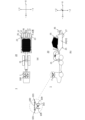
- FIG. 1A and 1B are schematic diagrams showing a towing vehicle and a scraper vehicle according to a first embodiment of the present invention, in which FIG. 1A is a top view and FIG. 1B is a side view.
- FIG. 2 is a block diagram of the main parts of the towing vehicle, scraper vehicle, and drone of the first embodiment. 2 is an enlarged view of a cross section of the wheel of FIG. 1( a ) as viewed from the direction of arrow A.
- 1 is a graph showing the change in weight of the scraper vehicle when excavated material is discharged from the bowl.
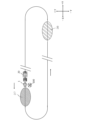
- FIG. 4 is a diagram illustrating a vibratory force caused by an eccentric member.
- FIG. 13 is a diagram showing a towing vehicle, a scraper vehicle, and a drone in a construction yard.
- FIG. 4 is a flowchart showing an operation executed by a first control device of the towing vehicle according to the first embodiment.
- FIG. 11 is a schematic diagram showing a towing vehicle and a scraper vehicle according to the second embodiment.
- the vertical direction is defined as the Z direction
- two axial directions that are orthogonal to each other in a horizontal plane are defined as the X direction and the Y direction.
- the scraper vehicle 20 is used as a towed vehicle towed by a large truck or other towing vehicle 1.
- the scraper vehicle 20 is a device that, while being towed by the towing vehicle 1, scrapes away soil and sand from a traveling surface such as the ground surface using a blade-like or spatula-like scraper 25, and stores the scraped soil and sand in a bowl 24 for transport.
- UAV unmanned aerial vehicle
- drone 100 flying in the sky captures images of the scraper vehicle 20 performing construction work.
- the scraper vehicle 20 is a construction device that repeats one cycle of excavation, transportation, discharge, compaction, and transportation while being towed by the towing vehicle 1.
- Fig. 1 is a schematic diagram showing a towing vehicle 1 and a scraper vehicle 20, which are driving vehicles of the first embodiment
- Fig. 1(a) is a top view
- Fig. 1(b) is a side view
- Fig. 2 is a block diagram of the main parts of the towing vehicle 1, the scraper vehicle 20, and the drone 100 of the first embodiment
- Fig. 3 is an enlarged view of the cross section of two wheels 27 in Fig. 1(a) as viewed from the direction of the arrow A.
- a towing vehicle 1 tows a scraper vehicle 20, and is connected (coupled) to the scraper vehicle 20 by a hitch 21 which is a coupling device.
- the hitch 21 is detachable from the towing vehicle 1 and has a flexible ball joint (not shown) provided at one end on the towing vehicle 1 side.
- the towing vehicle 1 of the first embodiment is an automatic driving type or a remote driving type without a driver's seat.
- the towing vehicle 1 is driven (propelled) by a fuel cell 2 (see Fig. 2) instead of an internal combustion engine, and an in-wheel motor 3 (see Fig. 2) provided on each of the two front wheels and the four rear wheels.
- the in-wheel motor 3 may be provided so as to be coaxially connected to the hubs of the front and rear wheels.
- the towing vehicle 1 may be a type having a driver's seat, and may use an internal combustion engine.
- the towing vehicle 1 of this first embodiment also has a hydrogen tank 4 that supplies hydrogen to the fuel cell 2, a storage battery 5, a Global Navigation Satellite System (GNSS) 6, a takeoff and landing section 7, a power transmission device 8, a first communication device 9, a hydraulic pump 10, a speedometer 11, a first memory 12, and a first control device 13.
- GNSS Global Navigation Satellite System
- the towing vehicle 1 of this first embodiment also has a hydrogen tank 4 that supplies hydrogen to the fuel cell 2, a storage battery 5, a Global Navigation Satellite System (GNSS) 6, a takeoff and landing section 7, a power transmission device 8, a first communication device 9, a hydraulic pump 10, a speedometer 11, a first memory 12, and a first control device 13.
- GNSS Global Navigation Satellite System
- the fuel cell 2 is a power generation device that generates electricity by electrochemically reacting hydrogen and oxygen.
- the hydrogen tank 4 stores hydrogen compressed to several tens of MPa, and supplies hydrogen to the fuel cell 2 via a hydrogen supply passage (not shown).
- the storage battery 5 is a secondary battery that stores the electric power generated by the fuel cell 2.
- the storage battery 5 can supply the stored electric power to the motor 3 and to a storage battery 33 provided in the scraper vehicle 20 via a connector (not shown). Although some parts are omitted from the block diagram of FIG. 2, each unit of the towing vehicle 1 is supplied with power from the fuel cell 2 or the storage battery 5 .
- the fuel cell 2 and hydrogen tank 4 are preferably placed on the front side (-X direction side) of the towing vehicle 1.
- an internal combustion engine and a driver's seat have been placed in the front of the towing vehicle 1.
- the internal combustion engine and driver's seat are omitted, so a large space can be provided in front of the towing vehicle 1, making it possible to place many hydrogen tanks 4 and ensuring freedom in the placement of the fuel cell 2, etc.
- the GNSS 6 measures the position of the towing vehicle 1 by using artificial satellites.
- the takeoff and landing section 7 is provided on the top of the towing vehicle 1, and has a flat surface large enough to allow takeoff and landing of the drone 100.
- the takeoff and landing section 7 may be formed on an upper part such as the hood instead of the top of the towing vehicle 1, and may be large enough to allow takeoff and landing of multiple drones 100.
- the takeoff and landing section 7 is provided with a power transmitting device 8 that supplies power to the power receiving device 103 of the drone 100 by wireless power supply, as shown in FIG. 2 .
- the power transmission device 8 employs wireless power supply.
- Wireless power supply supplies power to the power receiving device 103 in a non-contact manner, and known methods include magnetic resonance and electromagnetic induction.
- the power transmission device 8 in the first embodiment includes a power source, a control circuit, and a power transmission coil. This power transmission coil is preferably provided in the takeoff and landing section 7.
- a contact-type power supply method may be used instead of wireless power supply.
- metal contacts may be provided on each of the power transmission device 8 and the power receiving device 103, and power may be supplied by mechanically connecting the contacts.
- the first communication device 9 is a wireless communication unit that accesses a wide area network such as the Internet or a third communication device 106 associated with the second communication device 49 described below. Each of the first communication device 9, the second communication device 49, and the third communication device 106 can also communicate with a host computer installed away from the civil engineering site. In this first embodiment, the first communication device 9 communicates with the third communication device 106 of the drone 100 to transmit the travel route of the towing vehicle 1, the travel speed of the towing vehicle 1, data related to the scraper vehicle 20 (e.g., the dimensions of the scraper vehicle 20), the flight route of the drone 100, imaging conditions, etc.
- a wide area network such as the Internet
- third communication device 106 associated with the second communication device 49 described below.
- Each of the first communication device 9, the second communication device 49, and the third communication device 106 can also communicate with a host computer installed away from the civil engineering site.
- the first communication device 9 communicates with the third communication device 106 of the drone 100 to transmit the travel route of the towing vehicle 1,
- the hydraulic pump 10 uses the motor 3 or the engine as a power source to pressurize the hydraulic oil, and drives a number of hydraulic cylinders (not shown) provided in the scraper vehicle 20 and a hydraulic motor 46 (described below).
- the scraper vehicle 20 is also provided with branch pipes (not shown) and flow control valves (not shown) for branching the pressurized hydraulic oil and supplying it to a number of hydraulic cylinders and hydraulic motors (not shown).
- the speedometer 11 detects the speed of the towing vehicle 1, and is, for example, a vehicle speed sensor that detects the number of rotations of a shaft connected to the front wheels.
- various sensors such as a sensor that uses the output of GNSS6, may be used for speed detection.
- the method using the Doppler effect described in JP 2019-22108 A may be used for speed detection using GNSS6.
- the first memory 12 is a non-volatile memory (e.g., a flash memory) that stores map information of the civil engineering site (construction yard), a program for automatically driving the towing vehicle 1, a program for driving and controlling the drone 100, and a program for controlling the scraper 25 and hydraulic pump 10 described below.
- the first memory 12 also stores various data sent from the scraper vehicle 20 and the drone 100, and in particular stores data regarding weight changes in the scraper vehicle 20 obtained from calibration described below.
- the first control device 13 is equipped with a CPU and is a control device that controls the towing vehicle 1, the scraper vehicle 20, and the drone 100. In this first embodiment, the first control device 13 performs automatic driving of the towing vehicle 1 at the civil engineering site, drive control of the drone 100, drive control of the scraper 25 described below and a number of hydraulic cylinders (not shown) provided on the scraper vehicle 20. The control by the first control device 13 will be described later using the flowchart of FIG. 7.
- the scraper vehicle 20 In addition to the hitch 21, the scraper vehicle 20 has a frame 23, a bowl 24, a scraper 25, wheels 27, a strain gauge 28, an accelerometer 29 (see FIG. 2 ), and a load cell 30. In the first embodiment, the frame 23 and the bowl 24 form a main body 22.
- the scraper vehicle 20 also has a storage battery 33 (see FIG. 2 ), which is a secondary battery, a blade 35 , a connection portion 36 , and a rolling device 40 .
- the scraper vehicle 20 has a second memory 48 that stores various data, a second communication device 49, and a second control device 50 that controls the entire scraper vehicle 20.
- the frame 23 is a supporting member made of metal, and in this first embodiment, supports the bowl 24, the blade 35, a fixed axle 41 (described later), and the like.
- the bowl 24 has an open top and receives excavated material such as soil and sand excavated by the scraper 25 through an opening (not shown).
- the opening (not shown) formed in the bowl 24 is opened and closed by an opening/closing hydraulic cylinder (not shown) using hydraulic pressure from the hydraulic pump 10.
- the opening (not shown) is provided on the -X side of the scraper 25, which will be described later.
- the scraper 25 is a blade- or spatula-shaped member for scraping off soil and sand from a traveling surface such as the ground, and in the first embodiment, is provided integrally with the bottom of the bowl 24.
- the scraper 25 and an opening (not shown) extend along the vehicle width direction (Y direction) of the bowl 24, and have a dimension slightly smaller than the dimension of the bowl 24 in the vehicle width direction. Since the bowl 24 and the scraper 25 are provided integrally, the scraper 25 can dig into the ground surface and excavate soil and sand by tilting the bowl 24 toward the ground surface using a hydraulic cylinder for changing the position (not shown).
- the material excavated by the scraper 25 is accommodated in the bowl 24 by opening an opening (not shown) using a hydraulic cylinder for opening and closing (not shown).
- the bowl 24 When excavation by the scraper 25 is completed, the bowl 24 is tilted toward the ground by a hydraulic cylinder for changing the position (not shown), and the scraper 25 is lifted off the ground. At this time, the opening of the bowl 24 (not shown) is closed by a hydraulic cylinder for opening and closing (not shown).
- the wheels 27 are driven wheels that rotate when towed by the towing vehicle 1, and in this first embodiment, there are two wheels on the -Y side and two wheels on the +Y side, making a total of four wheels.
- the weight of the scraper vehicle 20 and the weight of the excavated material contained in the bowl 24 are applied to these four wheels 27, and these weights become parameters when compacting the ground surface in the compaction process described below.
- the number of wheels 27 is not limited to this, and there may be two wheels or six or more wheels.
- the wheels 27 have tires 27b attached to the outer periphery of the wheels 27a.
- the wheels 27 may be provided at the front and rear of the scraper vehicle 20 to serve as the front and rear wheels.
- the strain gauge 28 is a metal resistor, and is, for example, attached to the lower part of the hitch 21, which is the object to be measured, via an electrical insulator.
- the strain gauge 28 measures strain by changing the resistance value as the metal expands and contracts in proportion to the force applied to the hitch 21.
- the load of the excavated material is applied to the bowl 24.
- the load of the bowl 24 is applied separately to a flexible ball joint (not shown) and the wheels 27. Since part of the load of the bowl 24 is supported by the flexible ball joint (not shown), a tensile stress acts on the lower part of the hitch 21.
- the strain gauge 28 measures the change in resistance value caused by the tensile stress of the hitch 21, and the second control device 50 can measure the weight of the excavated material in the bowl 24 from the resistance value detected by the strain gauge 28.
- the accelerometer 29 detects the acceleration acting on the scraper vehicle 20, and any type of type can be used, such as mechanical, optical, or semiconductor.
- the accelerometer 29 can be provided, for example, on the frame 23 or the connection part 36, and detects acceleration in the Z-axis direction, but is not limited to this and may also detect acceleration in the X-axis or Y-axis directions.
- the load cell 30 is provided on the underside of the fixed axle 41 described below so that the load of the excavated material in the bowl 24 acting on the wheel 27 can be detected.
- Various types of load cells 30 can be used, such as piezoelectric load cells and strain load cells. Although two load cells 30 are shown for one wheel 27 in FIG. 3, the number of load cells 30 may be one or three or more.
- the load cell 30 may be provided on the upper surface of the fixed axle 41 described below, or on both the upper and lower surfaces.
- a pressure gauge may be provided instead of the load cell 30.
- the storage battery 33 stores the electricity generated by the fuel cell 2. The electricity stored in the storage battery 33 is supplied to each unit of the scraper vehicle 20.
- the blade 35 is a metal mechanical part that discharges the excavated material contained in the bowl 24 from the aforementioned opening (not shown) toward the ground surface during the discharge process.
- the blade 35 is located in the +X direction of the bowl 24 except during the discharge process, and during the discharge process it moves in the -X direction of the bowl 24 by a discharge hydraulic cylinder (not shown) to discharge the excavated material.
- connection part 36 is a metal mechanical part provided at the rear (+X direction) of the frame 23.
- the connection part 36 is a member that connects the scraper vehicles 20 together.
- the connection part 36 is a member that connects a pusher such as a bulldozer.
- the connection part 36 supports the fixed axle 41 described below together with the frame 23.
- the rolling device 40 is a device that uses each of the four wheels 27 to roll the ground surface from which the excavated material has been discharged. As shown in FIG. 3, the rolling device 40 has a fixed axle 41, vibration-proof members 42, bearings 43, and a pair of vibration excitation devices 44. The rolling device 40 is provided in a space formed by two adjacent wheels 27 out of the four wheels 27, the frame 23, and the connection portion 36. The rolling device 40 rolls the ground surface using vibrations generated by the pair of vibration excitation devices 44. In this case, it is preferable that the four rolling devices 40 are driven synchronously.
- the fixed axle 41 is a metal member with a circular cross section, and is supported by the frame 23 and the connection part 36 via vibration-damping members 42 at both ends.
- the fixed axle 41 serves as a common axle for the two wheels 27.
- a pair of vibration exciters 44 is provided on the upper surface of the fixed axle 41.
- a flat seat is formed on the upper surface of the fixed axle 41 at the location where the pair of vibration exciters 44 are installed. Note that it is desirable to also form a flat seat at the location where the aforementioned load cell 30 is installed.
- the vibration-proofing members 42 are members that suppress the transmission of vibrations generated by the pair of vibration-exciting devices 44 to any part other than the wheels 27. As a result, the vibrations generated by the pair of vibration-exciting devices 44 are suppressed, and the measurement of the strain gauge 28 can be free of the effects of vibrations caused by driving the pair of vibration-exciting devices 44.
- the vibration-proofing members 42 are provided on both ends of the fixed axle 41, and vibration-proof rubber is used. Note that vibration-proofing materials or vibration-proofing mechanisms other than vibration-proof rubber may also be used as the vibration-proofing members 42.
- the bearing 43 rotatably supports the wheel 27, with the wheel 27a journaled by the outer ring and the inner ring fixed to the fixed axle 41.
- the bearing 43 is a bearing in which the inner ring is fixed and the outer ring rotates.
- the pair of vibration exciters 44 are devices that generate vibrations in the fixed axle 41, and include vibration exciter 44L provided on the left side of the wheel 27 and vibration exciter 44R provided on the right side of the wheel 27. Vibration exciter 44L and vibration exciter 44R have the same configuration and include an eccentric 45 (see Figures 2 and 5) and a hydraulic motor 46 that causes eccentric motion of this eccentric 45. In this first embodiment, a pair of vibration exciters 44 are provided for each of the four wheels 27, but only one vibration exciter 44 is shown in Figure 2 to avoid complicating the block diagram.
- the pair of vibration exciters 44 generate a vibration force in the vertical Z direction, and are designed not to generate a vibration force in other directions. Specifically, when the eccentric element 45L of the vibration exciter 44L moves eccentrically to the left, the eccentric element 45R of the vibration exciter 44R moves eccentrically to the right, and the centrifugal force generated by the eccentric element 45L is cancelled by the centrifugal force generated by the eccentric element 45R.
- the pair of vibration exciters 44 are controlled by the first control device 13, but may also be controlled by the second control device 50 described below.
- the second memory 48 may be any type of memory, and in this first embodiment, a non-volatile semiconductor memory (e.g., a flash memory) is used.
- the second memory 48 stores detection data detected by the strain gauge 28, accelerometer 29, and load cell 30, as well as calibration data, which will be described later.
- the second communication device 49 can communicate with the first communication device 9, the third communication device 106, and the host computer, and transmits various data stored in the second memory 48.
- the second control device 50 is equipped with a CPU (Central Processing Unit) and controls the entire scraper vehicle 20.
- the second control device 50 commands the towing vehicle 1 to decelerate or stop, invalidates the data detected by the load cell 30, or stops detection by the load cell 30.
- the drone 100 of the first embodiment includes a flight device 101, an imaging device 102, a power receiving device 103, a sensor group 104, a battery 105, a third communication device 106, a third memory 107, a UAV control device 108, and legs 109.
- the flight device 101 has a motor and multiple propellers (not shown), and generates thrust for lifting the drone 100 in the air and moving it in the air.
- the imaging device 102 is a digital camera that has a lens, an imaging element, an image processing engine, etc., and captures videos and still images. In this first embodiment, the imaging device 102 captures images of the finished shape excavated or compacted by the scraper vehicle 20 and the excavated material contained in the bowl 24.
- the lens of the imaging device 102 is attached to the side (front) of the drone 100, but the lens of the imaging device 102 may be attached to the underside of the drone 100, or multiple lenses may be provided on the drone 100.
- a movement mechanism may be provided to move the lens attached to the side toward the underside.
- a mechanism may be provided to rotate the imaging device 102 around the Z axis, so that the lens of the imaging device 102 can be positioned at any position around the Z axis.
- LiDAR Light Detection and Ranging
- LiDAR is a sensor that scans with an electromagnetic wave, such as an ultraviolet, visible light, or near-infrared pulsed laser, and detects information such as the distance to an object, the shape of the object, the material of the object, and the color of the object based on the emitted light and scattered light.
- the power receiving device 103 has a power receiving coil and a charging circuit provided on the legs 109 of the drone 100, and charges the battery 105 with power from the power transmitting device 51.
- the battery 105 is a secondary battery connected to the power receiving device 103, and may be, but is not limited to, a lithium ion secondary battery or a lithium polymer secondary battery.
- the battery 105 is capable of supplying power to the flight device 101, the imaging device 102, the third communication device 106, the third memory 107, and the UAV control device 108.
- the sensor group 104 includes a GNSS, an infrared sensor for avoiding collisions between the drone 100 and other devices (e.g., the scraper vehicle 260), a barometric sensor for measuring altitude, a magnetic sensor for detecting orientation, a gyro sensor for detecting the attitude of the drone 100, and an acceleration sensor for detecting the acceleration acting on the drone 100.
- a GNSS GNSS
- an infrared sensor for avoiding collisions between the drone 100 and other devices (e.g., the scraper vehicle 260)
- a barometric sensor for measuring altitude
- a magnetic sensor for detecting orientation
- a gyro sensor for detecting the attitude of the drone 100
- an acceleration sensor for detecting the acceleration acting on the drone 100.
- the third communication device 106 has a wireless communication unit and accesses a wide area network such as the Internet, and communicates with the first communication device 9, the second communication device 49, and the host computer's communication device.
- the third communication device 106 transmits image data captured by the imaging device 102 and detection results detected by the sensor group 104 to at least one of the first communication device 9 and the host computer's communication device, and transmits flight commands from the first communication device 9 or the host computer's communication device to the UAV control device 108.
- the third memory 107 is a non-volatile memory (e.g., a flash memory) that stores various data and programs for flying the drone 100, as well as image data captured by the imaging device 102 and detection results detected by the sensor group 104.
- a non-volatile memory e.g., a flash memory
- the UAV control device 108 includes a CPU, an attitude control circuit, a flight control circuit, and the like, and controls the entire drone 100.
- the UAV control device 108 also determines the timing of charging at the takeoff and landing section based on the remaining charge of the battery 105, and controls the imaging position, angle of view, frame rate, etc. of the imaging device 102.
- the legs 109 are metal members that support the drone 100 when the drone 100 lands on the takeoff and landing section 7. As described above, the legs 109 are also provided with a power receiving device 103. Note that although FIG. 1 illustrates one drone 100, multiple drones 100 may be used.
- the scraper vehicle 20 When the bowl 24 is empty, the scraper vehicle 20 weighs 20 tons, and therefore a load of 10 tons acts on the four wheels 27, which means that a load of 2.5 tons acts on each wheel 27. In addition, when the bowl 24 is fully loaded, the scraper vehicle 20 weighs 40 tons, and a load of 20 tons acts on the four wheels 27, which means that a load of 5 tons acts on each wheel 27.
- the measured values of the strain gauge 28 and the load cell 30 in several states are stored as a table in the second memory 48, it is possible to detect how the load acting on the strain gauge 28 and the load cell 30 changes from when the excavated material loaded in the bowl 24 is fully loaded to when it is emptied.
- the stroke of the discharge hydraulic cylinder (not shown) that drives the blade 35 can be detected to indicate the change in weight of the excavated material.
- the load acts on the strain gauge 28 and the load cell 30 when the towing vehicle 1 and the scraper vehicle 20 are stationary and when the towing vehicle 1 and the scraper vehicle 20 are moving. It is also possible to detect the measured value of either the strain gauge 28 or the load cell 30. It is also possible to obtain the weight change of the scraper vehicle 20 by simulation. It is preferable not to drive the rolling device 40 described below when performing this calibration. It is preferable to detect the load of the excavated material loaded in the bowl 24 by the strain gauge 28, since the vibratory force of the rolling device 40 acts on the load cell 30 when the rolling device 40 is driven in the actual rolling process.
- Figure 4 is a graph showing the change in weight of the scraper vehicle 20 when the excavated material is discharged from an opening (not shown) of the bowl 24.
- This graph can be obtained by the calibration described above.
- the blade 35 When discharging the excavated material, the blade 35 is driven in the -X direction at a constant rate by a hydraulic cylinder for discharge (not shown), so that the excavated material is discharged almost uniformly from the opening (not shown), resulting in a linear graph. Note that if the movement speed of the blade 35 is changed while discharging the excavated material, or if the movement of the blade 35 is stopped for a few seconds during discharging, the graph will become nonlinear. Note that, during calibration, it is preferable to measure data on the time it takes for the bowl 24 to become empty from a full load state.
- Fig. 5 is a diagram for explaining the excitation force caused by the eccentric member 45.
- the excitation force is the centrifugal force F acting in the -Z direction when the eccentric member 45 rotates at a radius r. If the mass of the eccentric member 45 is m and the angular velocity of the eccentric member 45 is ⁇ , then the centrifugal force F is expressed by Equation 1.
- F mr ⁇ 2 Equation 1
- the angular velocity ⁇ is expressed by Equation 2, where N is the number of rotations per minute of the eccentric 45 and ⁇ is the constant of the circumference of a circle.
- ⁇ 2 ⁇ N/60 Equation 2 Therefore, the centrifugal force F in Equation 1 can be expressed as Equation 3 using the rotation speed N.
- F mr( ⁇ N/30) 2 Equation 3
- the rolling force of one wheel 27 is the sum of the load acting on one wheel 27 and the vibratory force (centrifugal force F) acting on one wheel 27.
- the load on the wheel 27 decreases due to discharge, so the vibratory force needs to be increased to keep the rolling force of one wheel 27 constant.
- the vibratory force can be increased by increasing the rotation speed N.
- the first control device 13 increases the amount of hydraulic oil supplied by the hydraulic pump 10 to the pair of rolling devices 40 to increase the rotation speed of the hydraulic motor 46, thereby increasing the rotation speed of the eccentric 45 and increasing the vibration force to offset the decrease in the load on the wheels 27.
- Data on the weight change of the scraper vehicle 20 due to discharge obtained by this calibration may be transmitted from the scraper vehicle 20 to the towing vehicle 1, for example, when the towing vehicle 1 and the scraper vehicle 20 are connected.
- the host computer, the first control device 13, or the second control device 50 may perform calculations or create programs to determine the amount of hydraulic pressure to be supplied to the hydraulic motor 46 of the vibration device 44 based on the timing of this weight change.
- FIG. 6 is a diagram showing the towing vehicle 1, scraper vehicle 20, and drone 100 in the construction yard.
- the towing vehicle 1 and scraper vehicle 20 move counterclockwise as shown by the arrow in FIG. 6, and perform an excavation process in the excavation area 37, and a discharge process of the excavated material in the spreading area 38.
- a rolling process is performed to roll the spread excavated material.
- the movement from the excavation area 37 to the spreading area 38 is the transportation process, and the movement from the spreading area 38 to the excavation area 37 is the delivery process.
- FIG. 7 is a flowchart executed by the first control device 13, and the flowchart will be explained below, but the flowchart may be modified to be executed by the host computer or the second control device 50.
- the flowchart in FIG. 7 is assumed to start in the transport process in which the excavation in the excavation area 37 is completed and the towing vehicle 1 is moving to the spreading area 38 while towing the scraper vehicle 20.
- the first control device 13 requests the second control device 50 for the load weight of the excavated material loaded in the bowl 24 and stores it in the first memory 12. This is because the weight of the bowl 24 when it is fully loaded in the calibration does not necessarily match the load weight of the excavated material excavated in the actual excavation process.
- the drone 100 lands on the takeoff and landing section 7 in the transport process and the battery 105 is charged by the power transmitting device 8 and the power receiving device 103.
- the first control device 13 judges whether the excavated material loaded in the bowl 24 can be discharged in the spreading area 38 (step S1). If the GNSS 6 output indicates that the towing vehicle 1 has entered the spreading area 38 or is close to it, the first control device 13 proceeds to step S2, and if the towing vehicle 1 is still away from the spreading area 38, the first control device 13 repeats step S1. Here, the first control device 13 proceeds to step S2 assuming that the towing vehicle 1 is close to the excavation area 37. In addition, the first control device 13 instructs the UAV control device 108 of the drone 100, which has landed on the takeoff and landing section 7, to fly at the timing when the towing vehicle 1 enters the spreading area 38. This is to allow the imaging device 102 of the UAV control device 108 to image the ground surface compacted by the compaction device 40 from behind the scraper vehicle 20.
- the first control device 13 opens the opening (not shown) of the bowl 24 using an opening/closing hydraulic cylinder (not shown), and starts discharge by driving the blade 35 in the -X direction using a discharge hydraulic cylinder (not shown) (step S2).
- the first control device 13 When the first control device 13 starts the discharge process in step S2, it performs compaction in the compaction process (step S3).
- the first control device 13 controls the hydraulic pressure of the hydraulic pump 10 and drives the hydraulic motor 46 to perform compaction by the compaction device 40.
- the hydraulic pressure of the hydraulic pump 10 may be calculated by the first control device 13 based on data on the change in weight of the scraper vehicle 20 due to discharge stored in the first memory 12, or may be determined according to a program stored in the first memory 12. This allows the ground surface to be compacted with a substantially constant force regardless of changes in the weight of the scraper vehicle 20.
- the first control device 13 may use a correction coefficient based on the load weight of the excavated material excavated in the actual excavation process when performing the above calculation.
- the first control device 13 may also use a correction parameter based on the load weight of the excavated material excavated in the actual excavation process in the above program.
- the first control device 13 monitors the output of the speedometer 11 to control the speed of the towing vehicle 1 and keep the impulse acting on the ground surface constant. Also, instead of or in addition to controlling the hydraulic pressure of the hydraulic pump 10 described above, the first control device 13 may decelerate the scraper vehicle 20 as the weight of the scraper vehicle 20 becomes lighter. By decelerating the scraper vehicle 20, the number of times the compaction device 40 compacts per unit time can be increased, so that the ground surface can be compacted with an almost constant force.
- the compacted ground surface is imaged by the imaging device 102 of the drone 100.
- the imaging device 102 of the drone 100 By imaging the compacted ground surface with the imaging device 102 of the drone 100, a clear image can be captured because it is not affected by vibrations caused by the movement of the scraper vehicle 20 or vibrations caused when the compaction device 40 is driven, compared to when an imaging device is provided on the scraper vehicle 20.
- the imaging data captured by the imaging device 102 may be stored in the third memory 107, the first memory, or the host computer.
- the first control device 13 determines whether or not discharge is complete (step S4).
- the first control device 13 determines whether or not discharge is complete based on data on the time it takes for the bowl 24 to go from full to empty, measured during calibration.
- the first control device 13 may fly the drone 100 above the bowl 24 and determine whether or not the excavated material contained in the bowl 24 has been discharged by imaging with the imaging device 102.
- the first control device 13 proceeds to step S5 assuming that discharge is complete. Note that the first control device 13 continues the compaction in step S3 if discharge is not complete.
- the first control device 13 determines whether a predetermined time has elapsed (step S5). This is a step for determining whether compaction has ended, since compaction ends a predetermined time (for example, several seconds to several tens of seconds) after the discharge of the excavated material is completed. Here, the first control device 13 ends this flowchart, assuming that the predetermined time has elapsed. Note that if the predetermined time has not elapsed, the first control device 13 repeats step S5 until the predetermined time has elapsed.
- the first control device 13 controls the hydraulic pump 10 so that the sum of the load on the wheels 27 and the excitation force is approximately constant, so that the ground surface can be compacted with an approximately constant force regardless of changes in the weight of the scraper vehicle 20 during compaction.
- a highly accurate compaction process can be achieved with no variation in the compacting force.
- the first control device 13 performs the compaction process in parallel while performing the discharge process, thereby reducing the time required for the compaction process.
- the bowl 24 and scraper 25 do not need to be inclined toward the ground surface. Therefore, in the discharge process and rolling process, a hydraulic cylinder for changing position (not shown) is not used. For this reason, the piping between the hydraulic cylinder for changing position (not shown) and the hydraulic motor 46 may be partially shared, and the oil supply path may be switched by a directional control valve. This makes it possible to avoid complex piping.
- the load weight of the excavated material contained in the bowl 24 may be calculated or estimated from an image captured by the imaging device 102 of the drone 100. Since the volume of the bowl 24 is known, it is possible to detect the load weight of the excavated material by capturing an image of the excavated material loaded above the bowl 24 from the side (X-direction side or Y-direction side) of the scraper vehicle 20.
- a liquid supplying device 14 is provided for supplying liquid (e.g., water) to the excavated material depending on the moisture content of the excavated material.
- the liquid supply device 14 includes a liquid tank 15 and a supply unit 16.
- the liquid tank 15 is provided on the frame of the towing vehicle 1, and is a tank that stores water and the like.
- the water stored in the liquid tank 15 is supplied to the supply unit 16 provided on the scraper vehicle 20 by a pump and piping (not shown).
- the supply unit 16 is provided on the rear side (+X direction) of the scraper 25, in a position that does not contact the ground surface when the scraper 25 digs into the ground surface to excavate soil and sand. It is preferable that the dimension of the supply unit 16 in the vehicle width direction is approximately the same as the dimension of the scraper 25 in the vehicle width direction. In addition, it is preferable that a nozzle is provided in the supply unit 16.
- the first memory 12 stores the moisture content of the ground surface obtained by test construction carried out in advance at the construction yard.
- the first control device 13 supplies liquid to the discharged excavated material by the liquid supply device 14 during the discharge process so that the excavated material has a predetermined moisture content. This allows the rolling device 40 to roll the ground surface at a moisture content suitable for compacting the ground surface.
- the liquid supply device 14 is provided with an opening/closing valve (not shown), and the first control device 13 changes the opening/closing valve (not shown) from a closed state to an open state when supplying liquid.
- the drone 100 may supply liquid.
- the drone 100 may be supplied with liquid from the liquid tank 15.
- the drone 100 may be supplied with liquid from a tank other than the liquid tank 15.
- the discharge process and the rolling process are performed in parallel, but the discharge process and the rolling process may be performed separately.
- the excavated material loaded in the bowl 24 is not discharged, so the weight of the scraper vehicle 20 does not change.
- the hydraulic cylinder for opening and closing (not shown), the hydraulic cylinder for discharge (not shown), and the hydraulic cylinder for changing the attitude (not shown) are not driven, so if the piping between any of these hydraulic cylinders and the hydraulic motor 46 is partially shared and the oil supply path is switched by a directional control valve, the piping can be prevented from becoming complicated.
- the first and second embodiments are merely examples for explaining the present invention, and various modifications can be made without departing from the scope of the present invention. It is also possible to combine the first and second embodiments.
- the drone 100 may be configured to capture images and supply water simultaneously, and a drone 100 for capturing images and a drone 100 for supplying water may be provided separately. Also, the drone 100 may be omitted.
- a self-propelled scraper may be used as the scraper vehicle 20.
- a push-type driving vehicle that pushes the scraper vehicle 20 from behind may be used.
Landscapes
- Engineering & Computer Science (AREA)
- Structural Engineering (AREA)
- Life Sciences & Earth Sciences (AREA)
- Civil Engineering (AREA)
- Environmental & Geological Engineering (AREA)
- Agronomy & Crop Science (AREA)
- Architecture (AREA)
- Soil Sciences (AREA)
- General Life Sciences & Earth Sciences (AREA)
- Mining & Mineral Resources (AREA)
- Paleontology (AREA)
- General Engineering & Computer Science (AREA)
- Road Paving Machines (AREA)
Priority Applications (1)
| Application Number | Priority Date | Filing Date | Title |
|---|---|---|---|
| JP2024572839A JP7806309B2 (ja) | 2023-01-26 | 2023-09-20 | 建設装置 |
Applications Claiming Priority (2)
| Application Number | Priority Date | Filing Date | Title |
|---|---|---|---|
| US202363481617P | 2023-01-26 | 2023-01-26 | |
| US63/481,617 | 2023-01-26 |
Publications (1)
| Publication Number | Publication Date |
|---|---|
| WO2024157538A1 true WO2024157538A1 (ja) | 2024-08-02 |
Family
ID=91970193
Family Applications (1)
| Application Number | Title | Priority Date | Filing Date |
|---|---|---|---|
| PCT/JP2023/034131 Ceased WO2024157538A1 (ja) | 2023-01-26 | 2023-09-20 | 建設装置 |
Country Status (2)
| Country | Link |
|---|---|
| JP (1) | JP7806309B2 (https=) |
| WO (1) | WO2024157538A1 (https=) |
Citations (3)
| Publication number | Priority date | Publication date | Assignee | Title |
|---|---|---|---|---|
| JPH05331806A (ja) * | 1992-06-03 | 1993-12-14 | Oshima Noki Kk | 種蒔き装置を有する自走式路肩盛土成形機 |
| JP2017122317A (ja) * | 2016-01-05 | 2017-07-13 | 鹿島建設株式会社 | 自走式撒き出し装置及び撒き出し方法 |
| WO2022210978A1 (ja) * | 2021-03-31 | 2022-10-06 | 住友建機株式会社 | アスファルトフィニッシャ、及び路面舗装システム |
Family Cites Families (2)
| Publication number | Priority date | Publication date | Assignee | Title |
|---|---|---|---|---|
| JPS4819303U (https=) * | 1971-07-13 | 1973-03-05 | ||
| JP7075384B2 (ja) | 2019-09-24 | 2022-05-25 | 日立建機株式会社 | 転圧機械 |
-
2023
- 2023-09-20 JP JP2024572839A patent/JP7806309B2/ja active Active
- 2023-09-20 WO PCT/JP2023/034131 patent/WO2024157538A1/ja not_active Ceased
Patent Citations (3)
| Publication number | Priority date | Publication date | Assignee | Title |
|---|---|---|---|---|
| JPH05331806A (ja) * | 1992-06-03 | 1993-12-14 | Oshima Noki Kk | 種蒔き装置を有する自走式路肩盛土成形機 |
| JP2017122317A (ja) * | 2016-01-05 | 2017-07-13 | 鹿島建設株式会社 | 自走式撒き出し装置及び撒き出し方法 |
| WO2022210978A1 (ja) * | 2021-03-31 | 2022-10-06 | 住友建機株式会社 | アスファルトフィニッシャ、及び路面舗装システム |
Also Published As
| Publication number | Publication date |
|---|---|
| JPWO2024157538A1 (https=) | 2024-08-02 |
| JP7806309B2 (ja) | 2026-01-26 |
Similar Documents
| Publication | Publication Date | Title |
|---|---|---|
| JP7755041B2 (ja) | 移動装置および無人飛行装置 | |
| JP7328212B2 (ja) | 建設機械の運転支援システム、建設機械 | |
| JP7436593B2 (ja) | 建設機械 | |
| JP7787864B2 (ja) | 建設機械のアシスト方法 | |
| CN107304560B (zh) | 包括铰接接头测力的压实系统 | |
| US11619028B2 (en) | Shovel | |
| JP7043300B2 (ja) | 作業機械の走行経路を計画するためのシステム、方法、及び作業機械 | |
| FR2866114A1 (fr) | Banc de test mobile pour pneumatiques, et procede de mise en oeuvre d'un tel banc de test | |
| KR20160022065A (ko) | 교량 내부 진단 시스템 | |
| JP7549164B2 (ja) | 建設機械システム | |
| JP7806309B2 (ja) | 建設装置 | |
| JP7754929B2 (ja) | 建設機械 | |
| JP7629520B2 (ja) | 建設機械ならびに掘削物調整方法 | |
| CN115343701A (zh) | 针对地面压实作业机器对地面特征的实时表面扫描和估计 | |
| WO2024134982A1 (ja) | 建設装置および建設装置の制御方法 | |
| WO2021014729A1 (ja) | スクレーパ車両 | |
| WO2023119737A1 (ja) | トレイン式スクレーパ車両 | |
| WO2023089891A1 (ja) | スクレーパ車両および牽引車両 | |
| US20260084763A1 (en) | Working vehicle | |
| WO2022185666A1 (ja) | 建設機械 | |
| AU2024369464A1 (en) | Display control device, display control system, and display control method | |
| JPWO2021014729A1 (ja) | スクレーパ車両 |
Legal Events
| Date | Code | Title | Description |
|---|---|---|---|
| 121 | Ep: the epo has been informed by wipo that ep was designated in this application |
Ref document number: 23918495 Country of ref document: EP Kind code of ref document: A1 |
|
| WWE | Wipo information: entry into national phase |
Ref document number: 2024572839 Country of ref document: JP |
|
| NENP | Non-entry into the national phase |
Ref country code: DE |
|
| 122 | Ep: pct application non-entry in european phase |
Ref document number: 23918495 Country of ref document: EP Kind code of ref document: A1 |