WO2024155153A1 - 전해동박용 부정형 구리 소재 및 이의 제조방법 - Google Patents
전해동박용 부정형 구리 소재 및 이의 제조방법 Download PDFInfo
- Publication number
- WO2024155153A1 WO2024155153A1 PCT/KR2024/000975 KR2024000975W WO2024155153A1 WO 2024155153 A1 WO2024155153 A1 WO 2024155153A1 KR 2024000975 W KR2024000975 W KR 2024000975W WO 2024155153 A1 WO2024155153 A1 WO 2024155153A1
- Authority
- WO
- WIPO (PCT)
- Prior art keywords
- copper
- irregular
- copper foil
- copper material
- molten
- Prior art date
- Legal status (The legal status is an assumption and is not a legal conclusion. Google has not performed a legal analysis and makes no representation as to the accuracy of the status listed.)
- Ceased
Links
Images



Classifications
-
- B—PERFORMING OPERATIONS; TRANSPORTING
- B22—CASTING; POWDER METALLURGY
- B22D—CASTING OF METALS; CASTING OF OTHER SUBSTANCES BY THE SAME PROCESSES OR DEVICES
- B22D21/00—Casting non-ferrous metals or metallic compounds so far as their metallurgical properties are of importance for the casting procedure; Selection of compositions therefor
- B22D21/02—Casting exceedingly oxidisable non-ferrous metals, e.g. in inert atmosphere
-
- B—PERFORMING OPERATIONS; TRANSPORTING
- B22—CASTING; POWDER METALLURGY
- B22F—WORKING METALLIC POWDER; MANUFACTURE OF ARTICLES FROM METALLIC POWDER; MAKING METALLIC POWDER; APPARATUS OR DEVICES SPECIALLY ADAPTED FOR METALLIC POWDER
- B22F1/00—Metallic powder; Treatment of metallic powder, e.g. to facilitate working or to improve properties
- B22F1/05—Metallic powder characterised by the size or surface area of the particles
-
- B—PERFORMING OPERATIONS; TRANSPORTING
- B22—CASTING; POWDER METALLURGY
- B22F—WORKING METALLIC POWDER; MANUFACTURE OF ARTICLES FROM METALLIC POWDER; MAKING METALLIC POWDER; APPARATUS OR DEVICES SPECIALLY ADAPTED FOR METALLIC POWDER
- B22F9/00—Making metallic powder or suspensions thereof
- B22F9/02—Making metallic powder or suspensions thereof using physical processes
- B22F9/06—Making metallic powder or suspensions thereof using physical processes starting from liquid material
- B22F9/08—Making metallic powder or suspensions thereof using physical processes starting from liquid material by casting, e.g. through sieves or in water, by atomising or spraying
-
- C—CHEMISTRY; METALLURGY
- C22—METALLURGY; FERROUS OR NON-FERROUS ALLOYS; TREATMENT OF ALLOYS OR NON-FERROUS METALS
- C22C—ALLOYS
- C22C9/00—Alloys based on copper
-
- C—CHEMISTRY; METALLURGY
- C25—ELECTROLYTIC OR ELECTROPHORETIC PROCESSES; APPARATUS THEREFOR
- C25D—PROCESSES FOR THE ELECTROLYTIC OR ELECTROPHORETIC PRODUCTION OF COATINGS; ELECTROFORMING; APPARATUS THEREFOR
- C25D3/00—Electroplating: Baths therefor
- C25D3/02—Electroplating: Baths therefor from solutions
- C25D3/38—Electroplating: Baths therefor from solutions of copper
Definitions
- the present invention relates to an irregular copper material for electrolytic copper foil and a method of manufacturing the same. Specifically, the present invention relates to an irregular copper material for electrolytic copper foil that not only has excellent dissolution performance when dissolved in an electrolyte solution for manufacturing electrolytic copper foil, but also ensures operational stability when manufacturing electrolytic copper foil and enables cost reduction due to a simple manufacturing process and a manufacturing method thereof. .
- Electrolytic copper foil is made by rotating a large titanium drum as a cathode slowly in an electrolyte solution, such as a copper sulfate solution, and copper (Cu), which is electrically positive, adheres to the titanium drum and precipitates precipitated copper foil. It is manufactured by a continuous plating method obtained by ⁇ ) and is used for copper-bonded laminates for printed wiring boards and building materials, especially secondary battery negative plates.
- an electrolyte solution such as a copper sulfate solution, and copper (Cu)
- the copper sulfate solution has been manufactured by cutting a copper wire to a certain size and dissolving it in a sulfuric acid solution, which is an electrolyte.
- the sulfuric acid solution is called 'electrolyte'
- the copper added to dissolve in this electrolyte is called 'copper material for electrolytic copper foil'.
- a linear copper material with a circular cross-sectional shape and cut to a certain length has been used as the copper material for this electrolytic copper foil.
- Figure 1 is a flow chart of the raw material manufacturing process of a conventional linear copper material for electrolytic copper foil
- Figure 2 is a photograph of the external appearance (a) and microstructure (b) of a copper wire cut to a certain length as a conventional linear copper material for electrolytic copper foil.
- the linear copper material for electrolytic copper foil consists of a supply and demand stage of raw materials such as electrolytic copper (cathode) or copper scrap, and a stage of manufacturing the raw materials into wire rods through casting, casting + rolling, or casting + rolling + drawing. , can be manufactured by a method including the steps of washing and cutting the manufactured wire.
- electrolytic copper foil can be manufactured by dissolving cut linear copper material, which is the raw material for electrolytic copper foil, in sulfuric acid solution, which is an electrolyte.
- the conventional method of manufacturing electrolytic copper foil uses a linear copper material, which is a cut copper wire as shown in Figure 2, as a material for the electrolytic copper foil, and the cut linear copper material is manufactured by rolling, drawing, and cutting processes.
- a linear copper material which is a cut copper wire as shown in Figure 2
- the cut linear copper material is manufactured by rolling, drawing, and cutting processes.
- oil components such as rolling oil and drawing oil are adhered to the material, and a degreasing cleaning process to remove these oil components is essential.
- the process is complicated, which increases the cost of electrolytic copper foil. .
- the cut linear copper material is manufactured in a small size to improve the dissolution performance in the electrolyte solution and is usually manufactured in a shape of 2 to 4 mm in diameter and 30 to 100 mm in length.
- electrolyte circulation and air are used during the electrolyte dissolution process.
- workability is deteriorated because the cut linear copper material falls into the bottom of the plate perforated with a diameter of 10 mm provided at the bottom of the dissolution tank for air supply.
- the internal crystal grain structure of the linear copper material is formed to have an average grain size of about 5 ⁇ m by grain refinement as shown in Figure 2b while going through continuous casting, rolling, and drawing processes. Therefore, this linear copper material has a relatively high grain boundary density, which accelerates the passivation of the surface of the linear copper material, resulting in a problem that the dissolution performance of the linear copper material in the electrolyte solution deteriorates.
- the purpose of the present invention is to provide an irregular copper material with excellent dissolution performance when dissolved in an electrolyte solution for manufacturing electrolytic copper foil and a method for manufacturing the same.
- the purpose of the present invention is to provide an irregular copper material and a manufacturing method thereof that ensure operational stability when manufacturing electrolytic copper foil and can reduce the cost of electrolytic copper foil by simplifying the manufacturing process.
- an irregular copper material for electrolytic copper foil which is irregular in shape, has an area of 3 mm2 or more, and includes a cross section with an average internal porosity of 1 to 20%.
- an irregular copper material for electrolytic copper foil is provided, characterized in that the average internal porosity is 5 to 15%.
- Equation 1 the bulk density defined by Equation 1 below is 1.0 to 3.0 g/cm 3 .
- the total mass of the irregular copper material refers to the total mass of the irregular copper material filled in a cubic box measuring 5 cm x 5 cm x 5 cm in width x length x height.
- an amorphous copper material for electrolytic copper foil is provided, characterized in that the oxygen content is 20 to 1,000 ppm.
- an amorphous copper material for electrolytic copper foil is provided, characterized in that the Cu content is 99.7 to 99.99% and the impurity content is 100 to 3,000 ppm.
- a manufacturing method for copper materials Provides a manufacturing method for copper materials.
- a method for manufacturing an irregular copper material for electrolytic copper foil is provided, characterized in that it further includes a refining step to remove impurities in the molten copper before performing step c).
- a method for manufacturing an irregular copper material for electrolytic copper foil characterized in that the melt temperature of the molten copper solution is 1,090 to 1,400 ° C.
- a method for manufacturing an irregular copper material for electrolytic copper foil characterized in that the oxygen content of the molten copper solution is 20 to 1,000 ppm.
- step c) is characterized in that the molten copper solution from the copper raw material is dispersed in the form of irregular molten copper droplets and precipitated into cooling water contained in a water tank while cooling to produce an irregular copper material.
- the molten copper solution from the copper raw material is dispersed in the form of irregular molten copper droplets and precipitated into cooling water contained in a water tank while cooling to produce an irregular copper material.
- step c) the molten copper liquid from the copper raw material is discharged from the molten metal nozzle to a collision plate provided adjacent to a water tank containing cooling water, thereby dispersing it in the form of irregular molten copper droplets and depositing them into the cooling water contained in the water tank.
- a method for manufacturing an irregular copper material for electrolytic copper foil characterized in that the irregular copper material is manufactured by cooling while cooling.
- a method for manufacturing an irregular copper material for electrolytic copper foil characterized in that the distance between the discharge port of the molten metal nozzle and the upper surface of the collision plate is 50 to 1500 mm.
- step c) provides a method of manufacturing an irregular copper material for electrolytic copper foil, characterized in that the molten copper liquid is discharged while rotating the molten metal nozzle and cooled while precipitating it into the cooling water contained in the water tank. do.
- a method for manufacturing an irregular copper material for electrolytic copper foil characterized in that the discharged molten copper liquid is dispersed in the form of irregular molten copper droplets by passing the discharged molten copper liquid through a mesh network installed adjacent to the molten metal nozzle.
- the molten metal nozzle includes a plurality of fine nozzles, and the molten copper liquid discharged from each of the plurality of fine nozzles is combined into one and then dispersed in the form of irregular molten copper droplets. Manufacturing method is provided.
- the distance between the central axes of adjacent fine nozzles among the plurality of fine nozzles is 1 to 50 mm
- the inner diameter of the discharge port of one fine nozzle is 1 to 4 mm
- a virtual cross-sectional area is equal to the total cross-sectional area of the discharge ports of all fine nozzles.
- the discharge amount of the molten metal nozzle is 5 to 50 tons / h
- the vertical distance between the discharge port of the molten metal nozzle and the water surface of the cooling water is 50 to 1500 mm.
- a method for manufacturing an irregular copper material for electrolytic copper foil is provided. .
- an electrolytic copper foil manufactured from the copper material for the electrolytic copper foil is provided.
- dissolving the copper material for the electrolytic copper foil in an electrolyte solution attaching copper (Cu) to a drum that is electrically negative and rotating in the electrolyte solution, and obtaining copper foil from the drum to which the copper (Cu) is attached. It provides a method for manufacturing electrolytic copper foil, including the step.
- the amorphous copper material for electrolytic copper foil according to the present invention exhibits excellent dissolution performance, such as a rapid dissolution rate and a large amount of dissolution content when dissolved in an electrolyte solution through a specific internal porosity, bulk density, etc. on the premise of an irregular shape.
- the amorphous copper material for electrolytic copper foil according to the present invention has the effect of securing a specific internal porosity and ensuring excellent dissolution performance and productivity.
- the amorphous copper material for electrolytic copper foil according to the present invention has the effect of securing a specific bulk density and ensuring excellent dissolution performance and productivity.
- the amorphous copper material for electrolytic copper foil according to the present invention ensures operational stability when manufacturing electrolytic copper foil, and unlike linear copper materials, processes such as rolling, wire drawing, washing for degreasing, and cutting are not required, so the manufacturing process is simple and the cost of electrolytic copper foil is reduced. It shows excellent effects that enable savings.
- Figure 1 is a flow chart of a conventional linear copper material manufacturing process for electrolytic copper foil.
- Figure 2 is a photograph of the external appearance and microstructure of a conventional linear copper material for electrolytic copper foil.
- Figure 3 is a flow chart of the manufacturing process of irregular copper material for electrolytic copper foil according to the present invention.
- Figure 4 is a photograph of the external appearance and microstructure of an irregular copper material manufactured according to the manufacturing process of Figure 3.
- Figure 5 schematically shows the casting equipment used in the manufacturing process of the irregular copper material for electrolytic copper foil of Figure 3.
- Figure 6 schematically shows another embodiment of a casting device used in the manufacturing process of the irregular copper material for electrolytic copper foil of Figure 3.
- Figure 7 schematically shows one embodiment of the discharge surface of a molten metal nozzle applied to the casting apparatus of Figures 5 and 6.
- Figure 8 is an image taken with an optical microscope (x500) of a cross-section with an area of 3 mm2 or more to measure the internal porosity of the irregular copper material for electrolytic copper foil according to the present invention.
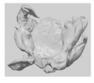
- Figure 9 shows an example in which the specific surface area of an irregular copper material for electrolytic copper foil according to the present invention was measured using 3D scanner equipment and software.
- Figure 10 shows a sample microstructure photograph taken with an optical microscope of the irregular copper material of the present invention.
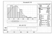
- FIG. 11 is a diagram showing the results of analyzing the image of the photo sample taken in FIG. 10 using an image analyzer.
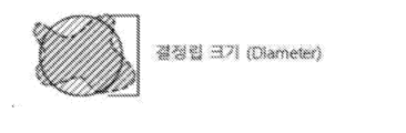
- Figure 12 shows an example of calculating the grain area through the diameter of a circle converted to have the same area as the grain area.
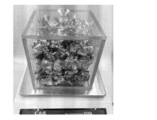
- Figure 13 shows a cubic-shaped acrylic box filled with copper material to measure bulk density.
- Figure 3 is a flow chart of the manufacturing process of the irregular copper material for electrolytic copper foil according to the present invention
- Figure 4 is a photograph of the external appearance and microstructure of the irregular copper material manufactured according to the manufacturing process of Figure 3
- Figure 5 is the irregular copper material for electrolytic copper foil of Figure 3. It schematically shows one embodiment of a casting device used in the copper material manufacturing process.
- the irregular copper material for electrolytic copper foil can be manufactured by a manufacturing method including steps a) to c) below.
- Raw material supply stage such as copper cathode or scrap
- a refining step may be additionally performed to remove impurities in the molten copper.
- Step c) can be performed, for example, using the casting device shown in FIG. 5.
- the molten copper liquid is collided from the molten metal nozzle onto a collision plate provided near a water tank containing cooling water such as water, and the molten copper liquid is irregular in shape due to the impact when it collides with the collision plate. It is dispersed in all directions in the form of droplets and cooled while settling into the cooling water contained in the water tank, forming an irregular copper material with an irregular shape having a specific bulk density, specific surface area, and crystal grain structure.
- indefinite shape means a shape whose outer shape cannot be defined as a specific shape such as a sphere, an elongated line, a cylinder, or a hexahedron.
- the molten metal nozzle and the collision plate may be fixed relative to each other or may move relative to each other.
- the molten copper liquid can be discharged as the molten metal nozzle rotates and collides with a stationary collision plate, or the copper liquid can be discharged from a stationary molten metal nozzle and collided with the rotating collision plate to produce an irregular copper material. .
- the size of the irregular copper material produced can be adjusted by adjusting the distance between the discharge port of the molten metal nozzle through which the molten copper liquid is discharged from the lower part of the molten metal tank containing the molten copper liquid and the upper surface of the collision plate to 50 mm to 1500 mm.
- the distance between the discharge port of the molten metal nozzle and the upper surface of the impingement plate is less than 50 mm, the molten copper liquid may not be sufficiently dispersed from the impingement plate and an excessively coarse irregular copper material may be formed.
- the distance is If it exceeds 1500 mm, the molten copper scattered from the collision plate may be excessively scattered in a too fine shape, resulting in the formation of an excessively fine irregular copper material.
- the oxygen content of the molten copper liquid may be adjusted to 20 to 1,000 ppm.
- the oxygen content of the molten metal is less than 20 ppm, it is difficult to control the shape of the irregular copper material formed from the molten copper solution scattered due to the influx of a large amount of hydrogen in the molten metal.
- the oxygen content is more than 1,000 ppm, the shape of the irregular copper material is formed due to cooling. When the copper material solidifies, a large amount of oxide may be generated, making it difficult to control the shape of the irregular copper material.
- the amorphous copper material for electrolytic copper foil may have an oxygen content of 20 to 1,000 ppm.
- the molten metal temperature of the copper solution melted in step b) may be 1,090°C or higher, preferably 1,090 to 1,400°C after refining.
- the molten metal may pre-solidify and the discharge port of the molten metal nozzle may be blocked, or a problem may occur in which the molten copper liquid that has fallen on the impingement plate is fused to the impingement plate. If the temperature exceeds 1,400°C, there is a problem in that the irregular molten copper droplets dispersed in all directions by falling on the collision plate fuse together again to form copper material with an excessively coarse shape.
- the method of dispersing the irregular molten copper droplets in all directions is not limited to colliding with the collision plate. .
- Figure 6 schematically shows another embodiment of a casting device used in the manufacturing process of the irregular copper material for electrolytic copper foil of Figure 3.
- molten copper can be immersed in cooling water by discharging molten copper while rotating the molten metal nozzle itself 360°.
- a mesh network is additionally installed around the molten metal nozzle. As the discharged molten copper passes through a mesh network, its size can be adjusted and immersed in cooling water.
- the size and shape of irregular molten copper droplets that collide with the collision plate and are dispersed in all directions can be more easily controlled.
- the amorphous copper material for electrolytic copper foil of the present invention manufactured according to the above manufacturing method embodiment has a shape whose outer shape cannot be defined as a specific shape such as a sphere, an elongated line, a cylinder, or a hexahedron, that is, the shape is not constant. It refers to a copper material with an indeterminate shape.
- an electrolytic copper foil can be manufactured by dissolving the irregular copper material prepared as above in a sulfuric acid electrolyte solution.
- irregular copper materials do not require rolling, drawing, and cutting processes when manufactured.
- rolling oil and drawing oil used in rolling and drawing are not used, the washing process for degreasing is also unnecessary.
- the manufacturing cost of electrolytic copper foil can be greatly reduced.
- Figure 7 schematically shows one embodiment of the discharge surface of a molten metal nozzle applied to the casting apparatus of Figures 5 and 6.
- the discharge surface of the molten metal nozzle applied to the casting apparatus of FIGS. 5 and 6 may include a plurality of fine nozzles.
- the irregular copper material manufactured by combining the molten copper discharged through each of the plurality of fine nozzles into one, dispersing in all directions in the form of droplets, and immersing in cooling water can have a specific internal porosity, and the internal porosity adjusted in this way is irregular.
- the solubility of copper materials in electrolyte can be maximized.
- the spacing (INT) between the central axes of adjacent fine nozzles is 1 to 50 mm
- the inner diameter (D) of the discharge port of one fine nozzle is 1 to 4 mm
- a virtual cross-sectional area is equal to the total cross-sectional area of the discharge ports of all fine nozzles.
- the diameter of the circle may be 10 to 100 mm.
- the discharge amount of the molten metal nozzle is 5 to 50 tons/h, and the vertical distance between the discharge port of the molten metal nozzle and the water surface of the cooling water may be 50 to 1500 mm.
- the internal porosity of the irregular copper material according to the present invention can be determined. can be controlled more precisely.
- Figure 8 is an image taken with an optical microscope (x500) of a cross-section with an area of 3 mm2 or more to measure the internal porosity of the irregular copper material for electrolytic copper foil according to the present invention.
- the black part in the image corresponds to a void
- the value measured as the ratio of the area occupied by the total voids in the black part corresponds to the internal porosity.
- the average internal porosity is calculated by selecting a cross-section of a copper material with an area of 3 mm2 or more and taking the maximum value of the total area ratio occupied by pores in 10 images taken with an optical microscope ( ⁇ 500 times) at a random position of the cross-section. Calculate the average of 8 values excluding the minimum value.
- the average internal porosity of the irregular copper material for electrolytic copper foil according to the present invention may be 1 to 20%, preferably 5 to 15%.
- the average internal porosity is less than 1%, the dissolution performance such as dissolution rate and dissolution amount in the electrolyte solution is greatly reduced, whereas when the average internal porosity is more than 20%, excessive pores inside the irregular copper material cause relatively low copper content. As the weight decreases, the productivity of the electrolytic copper foil may be greatly reduced.
- the irregular copper material has an irregular shape with an unspecified shape and an irregular cross-sectional shape, and has a specific surface area of 30 to 400 mm2/g, preferably 50 to 300 mm2/g. It can be.
- the specific surface area of the irregular copper material is less than 30 mm2/g, the solubility in the electrolyte may be greatly reduced, whereas if the specific surface area is more than 400 mm2/g, foreign substances may be introduced to the surface of the irregular copper material. It may be difficult to maintain the quality of the copper foil, and the local strength of the irregular copper material may be greatly reduced, making it difficult to maintain its size and shape.
- Figure 9 shows an example in which the specific surface area of an irregular copper material for electrolytic copper foil according to the present invention was measured using 3D scanner equipment and software.
- the specific surface area of the irregular copper material can be measured using 3D scanner equipment and software.
- the 3D scanner equipment can use MetraSCAN BLACK Elite (manufacturer: CREAFORM), HandySCAN BLACK Elite (manufacturer: CREAFORM), etc.
- the software can use 3D SYSTEM, GEOMAGIC DesignX, etc.
- the irregular copper material to be measured is placed on the holder of the 3D scanner equipment in a 3-dimensional space at the level of 3 m, and a 3D scan is performed by moving around the irregular copper material with a laser.
- the shape of the scanned irregular copper material is It is displayed in real time, and the total specific surface area of the irregular copper material can be automatically measured from the 3D scanned image through software.
- the irregular copper material has a relatively low grain boundary density with an average grain size of 50 to 300 ⁇ m, preferably 60 to 150 ⁇ m, thereby delaying surface passivation and sufficient dissolution in the electrolyte solution. Performance can be secured.
- the average grain size is less than 50 ⁇ m, such as the conventional linear copper material shown in FIG. 2, there is a problem that the dissolution performance in the electrolyte solution is reduced due to acceleration of surface passivation due to the relatively high grain boundary density.
- the specific surface area and grain size of the irregular copper material are determined by colliding with the molten copper liquid on the collision plate and scattering, as shown in Figure 5, without going through the rolling and drawing process like the conventional linear copper material, or as shown in Figure 6. This is achieved by scattering the molten copper liquid discharged from the rotating nozzle and then cooling it in cooling water.
- the average grain size can be measured according to the standard measurement method and standards of ASTM E 1382. Specifically, according to the standard measurement method and standards of ASTM E 1382, polishing is performed with an abrasive with a size of about 1 ⁇ m or more to remove scratches on the surface of the irregular copper material (ASTM E 1382 10.2), and polishing is performed The completed surface is etched flat with an etchant (ASTM E 1382 10.6), and the microstructure of the polished and etched surface at different positions is photographed using an optical microscope at least 5 times, with each photograph containing about 50 or more grains. (ASTM E 1382 12.1).
- the amorphous copper material of the present invention is not deformed by heat treatment, etc., and its crystal structure is an equiaxed grain, so the crystal structure is the same regardless of the shape and cross-sectional position, so any shape and cross-section can be selected. There will be no significant difference in the results if photographed (ASTM E 1382 9.1).
- the “average grain size” is measured by analyzing each microstructure photo taken with an optical microscope using the general-purpose software Image Analyzer.
- Image Analyzer a general-purpose software, is software that extracts meaningful information from images and has been developed and supplied by a number of optical microscope, stereo microscope, and medical device companies, and the average grain size of the amorphous copper material of the present invention is determined by the optical microscope.
- Nikon ECLIPSE MA200 was used as a microscope and Nikon NIS-Elements D was used as an image analyzer, but it is not limited thereto.
- Figure 10 shows a microstructure photograph sample of the irregular copper material of the present invention taken with an optical microscope
- Figure 11 is a diagram showing the results of analyzing the image of the photograph sample taken in Figure 10 with an image analyzer.
- the method for measuring “average grain size” from a sample photograph is to divide the sum of the areas of all grains included in the photograph by the number of all grains included in the photograph to obtain the average.
- the grain area can be obtained, and the average grain size can be obtained by calculating the diameter of a circle converted to have the same area as the average grain area as shown in FIG. 12 according to standard ISO 13383-1 3.3 (equivalent circle grain diameter). .
- the final average grain size can be obtained by calculating the average value of the average grain sizes measured from each sample photo.
- the irregular copper material may have a density of 8.88 to 8.96 g/cm3, a copper (Cu) content of 99.7 to 99.99%, and a total impurity content of 100 to 3,000 ppm.
- the copper content is low below 99.7% or the total impurity content is high above 3,000 ppm, foreign substances in the electrolyte solution during electrolytic copper foil production will interfere with the movement of copper ions, and copper ions will be deposited unevenly on the titanium drum. This may cause defects in the product.
- the higher the copper content the better, but if it exceeds 99.99%, there is a problem that productivity decreases and costs increase due to excessive specifications.
- the impurities include, for example, Pb (lead), Ag (silver), Ni (nickel), Fe (iron), Sn (tin), As (arsenic), Al (aluminum), Cd (cadmium), P ( There may be metals such as phosphorus, Sb (antimony), etc., but it is not limited to the examples listed.
- the content of each impurity is preferably 100 ppm or less.
- the irregular copper material may have a bulk density of 1.0 to 3.0 g/cm 3 .
- dissolution performance such as rapid dissolution rate and large dissolution content, can be improved when dissolved in an electrolyte solution.
- Figure 13 shows a cubic-shaped acrylic box filled with copper material to measure bulk density.
- the bulk density may mean the total mass of the copper material for a cubic volume of 5 cm x 5 cm x 5 cm in width x length x height, and can be defined as Equation 1 below.
- the total mass of the copper material refers to the total mass of the copper material filled in a cubic box measuring 5 cm x 5 cm x 5 cm in width x length x height.
- the total mass of the copper material is dropped into the cubic-shaped acrylic box from a height of 5 cm from the top of a cubic-shaped acrylic box measuring 5x5x5 cm in width x length x height, so that the cover of the cubic-shaped acrylic box is completely covered.
- the degree to which it can be closed can be calculated by measuring the total mass of the copper material filled to the top inside the cubic-shaped acrylic box.
- the width, length, and height of the cubic-shaped acrylic box are based on the dimensions of the inside of the box. In the embodiment of the present invention, an acrylic box with a thickness of 5 mm was used, but the material and thickness of the box are such that the cubic shape can be maintained. There is no particular limitation.
- the bulk density of the irregular copper material is less than 1.0 g/cm 3
- the surface area of the irregular copper material in contact with the electrolyte increases, but the amount of copper that can actually be charged into the dissolution tank of a certain volume is insufficient, leading to a problem of reduced productivity.
- the bulk density is greater than 3.0 g/cm 3
- the amount of copper that can be charged into a dissolution tank of a certain volume is sufficient, but the dissolution rate may be greatly reduced.
- the irregular copper material has a longest axis, which is the longest axis among the long axes in arbitrary cross sections, of 10 mm or more, preferably 10 to 75 mm, and a minor axis in arbitrary cross sections perpendicular to the cross section including the longest axis.
- the shortest axis, which is the shortest axis, may be 5 mm or less, preferably 1 to 5 mm.
- the longest axis is less than 10 mm, copper material may fall into the bottom of the plate perforated with a diameter of 10 mm provided at the bottom of the electrolyte tank for electrolyte circulation and air supply during the electrolyte dissolution process, which may cause a problem of reduced workability.
- the specific surface area of the copper material is insufficient, and the dissolution performance in the electrolyte solution may be greatly reduced.
- the shortest axis is greater than 5 mm, the specific surface area of the copper material may be insufficient and the dissolution performance in the electrolyte solution may be greatly reduced.
- the longest and shortest axes of the irregular copper material can be measured using a device such as a vernier caliper, and there is no particular limitation as long as the device can measure the length.
- the present invention relates to an electrolytic copper foil manufactured from the previously described amorphous copper material for electrolytic copper foil and a method of manufacturing the same.
- the manufacturing method of the electrolytic copper foil includes the steps of dissolving the amorphous copper material for the electrolytic copper foil in an electrolyte solution, the step of attaching copper (Cu) to a drum that is electrically negative and rotating in the electrolyte solution, and the copper (Cu) is different. It may include obtaining copper foil from the attached drum.
- the solubility of the irregular copper material is determined by precipitating the irregular copper material according to Examples and Comparative Examples in 4 L of sulfuric acid solution at a temperature of 50°C and concentration of 30% for 24 hours under air blowing conditions, and then measuring the weight reduced by dissolution. By measurement, the dissolved amount (g/L) was calculated.
- productivity was measured by measuring the number of 1 L simulated melting tanks (cylindrical melting tanks with a diameter of 11.3 cm and a height of 10 cm) that can be filled with a total of 1 kg of amorphous copper material, and when the number of simulated melting tanks is 1 It was rated as 'high', if there were two, it was rated as 'medium', and if there were three or more, it was rated as 'low'.
- filling the irregular copper material means filling the irregular copper material as much as possible so that it does not protrude from the upper open surface of the simulated dissolution tank. However, the last dissolution tank does not need to be full.
- the amorphous copper materials of Examples 10 to 12, where the bulk density was adjusted to 1.0 to 3.0 g/cm3 on the premise of satisfying an appropriate internal porosity were confirmed to have particularly excellent solubility and productivity.
- the productivity of the irregular copper materials of Examples 8 and 9, whose bulk density was below the standard was confirmed to be relatively reduced, and the amorphous copper material of Examples 13 and 14, whose bulk density was above the standard, was confirmed to have a relatively reduced solubility. .
Landscapes
- Chemical & Material Sciences (AREA)
- Engineering & Computer Science (AREA)
- Materials Engineering (AREA)
- Metallurgy (AREA)
- Organic Chemistry (AREA)
- Mechanical Engineering (AREA)
- Chemical Kinetics & Catalysis (AREA)
- Electrochemistry (AREA)
- Electrolytic Production Of Metals (AREA)
- Crystallography & Structural Chemistry (AREA)
Abstract
본 발명은 전해동박용 부정형 구리 소재 및 이의 제조방법에 관한 것이다. 구체적으로, 본 발명은 전해동박 제조를 위해 전해액에 용해시 용해성능이 우수할 뿐만 아니라 전해동박 제조시 작업안정성이 확보되고 제조공정이 단순하여 원가 절감이 가능한 전해동박용 부정형 구리 소재 및 이의 제조방법에 관한 것이다.
Description
본 발명은 전해동박용 부정형 구리 소재 및 이의 제조방법에 관한 것이다. 구체적으로, 본 발명은 전해동박 제조를 위해 전해액에 용해시 용해성능이 우수할 뿐만 아니라 전해동박 제조시 작업안정성이 확보되고 제조공정이 단순하여 원가 절감이 가능한 전해동박용 부정형 구리 소재 및 이의 제조방법에 관한 것이다.
전해동박은 커다란 티타늄 드럼을 음극으로 하여 전해액, 예를 들어 황산구리 용액 내에서 천천히 회전시키면서 상기한 티타늄 드럼에 전기적으로 양극을 띄는 구리(Cu)가 달라붙어 석출되는 석출동(析出銅)을 동박(銅箔)으로 얻는 연속도금 방식에 의해 제조되는 것으로 프린트배선 기판용 동부착 적층판이나 건재, 특히 2차 전지 음극판 등에 사용되고 있다.
이 때, 황산구리 용액은 구리 선재(線材)를 일정한 크기로 절단하여 전해액인 황산 용액에 넣어 용해시켜 제조되어 왔다. 여기서 황산용액은 '전해액'이라 하고, 이러한 전해액에 용해시키기 위해 투입되는 구리는 '전해동박용 구리 소재' 라고 한다. 종래에는 이 전해동박용 구리 소재로서 단면 형상이 원형이고 일정한 길이로 절단한 선형 구리 소재를 사용하여 왔다.
도 1은 종래 전해동박용 선형 구리 소재의 원재료 제조공정의 순서도이고, 도 2는 종래 전해동박용 선형 구리 소재로서 일정한 길이로 절단된 구리 선재의 외형(a) 및 미세 조직(b) 사진이다.
도 1에 도시된 바와 같이, 전해동박용 선형 구리 소재는 전기동(cathode)이나 구리 스크랩(scrap) 등의 원재료 수급 단계, 원재료를 주조, 주조+압연 또는 주조+압연+신선을 통해 선재로 제조하는 단계, 제조한 선재를 세척 및 절단하는 단계 등을 포함하는 방법에 의해 제조될 수 있다. 한편, 전해동박은 전해동박용 원재료인 절단된 선형 구리 소재를 전해액인 황산 용액에 용해시킴으로써 제조될 수 있다.
종래 전해동박의 제조방법은 전해동박용 재료로서 도 2에 도시된 바와 같은 절단된 구리 선재인 선형 구리 소재를 사용하고, 절단된 선형 구리 소재는 압연, 신선, 절단 공정에 의해 제조될 때, 압연 및 신선시에 압연유 및 신선유 등의 기름 성분이 묻게 되어, 전해동박용 재료로 사용될 때에는 이러한 기름 성분을 제거하기 위한 탈지 세척 공정이 필수적으로 필요하게 되는 등 공정이 복잡하여 전해동박의 비용이 증가하는 문제가 있다.
또한, 절단된 선형 구리 소재는 전해액에 대한 용해성능을 향상시키기 위해 작은 사이즈로 제조되어 통상 직경 2 내지 4 ㎜ 및 길이 30 내지 100 ㎜의 형상으로 제조되는데, 이러한 경우 전해질 용해 공정시 전해액 순환 및 에어(air) 공급을 위해 용해조 수조 하부에 구비된 직경 10 ㎜로 타공된 플레이트 하부로 절단된 선형 구리 소재가 빠져 작업성이 저하되는 문제가 있다.
나아가, 선형 구리 소재의 내부 결정립 구조는 연속주조, 압연, 신선 공정을 거치면서 도 2b에 도시된 바와 같이 결정립 미세화에 의해 평균 결정립 크기가 5 ㎛ 수준으로 형성된다. 따라서, 이러한 선형 구리 소재는 상대적으로 높은 결정립계 밀도를 갖게 됨으로써 선형 구리 소재 표면의 부동태화가 가속화되어 결과적으로 전해액에 대한 선형 구리 소재의 용해성능이 저하되는 문제가 있다.
또한, 단면이 원형으로 일정한 형상인, 일정한 길이로 절단된 다량의 선형 구리 소재는 황산용액에 넣어졌을 때, 서로 중첩되어 쌓이게 됨으로써 선형 구리 소재들 간의 공간이 여의치 않아, 황산이 각 선형 구리 소재 표면에 침투해 들어가는 것을 어렵게 하여, 선형 구리 소재의 용해성능이 저하되는 원인이 되기도 한다.
그러므로, 구리 소재를 전해동박 제조를 위해 전해액에 용해시 용해성능이 우수할 뿐만 아니라 전해동박 제조시 작업안정성이 확보되고 제조공정이 단순하여 원가 절감이 가능한 구리 소재 및 이의 제조방법이 절실히 요구되고 있는 실정이다.
본 발명은 전해동박 제조를 위한 전해액에 용해시 용해성능이 우수한 부정형 구리 소재 및 이의 제조방법을 제공하는 것을 목적으로 한다.
또한, 본 발명은 전해동박 제조시 작업안정성이 확보되고 제조공정이 단순하여 전해동박의 원가 절감이 가능한 부정형 구리 소재 및 이의 제조방법을 제공하는 것을 목적으로 한다.
상기 과제를 해결하기 위해, 본 발명은,
전해동박용 부정형 구리 소재로서, 형상이 일정하지 않은 부정형이며, 면적이 3 ㎟ 이상이고 평균 내부공극률이 1 내지 20%인 단면을 포함하는, 전해동박용 부정형 구리 소재를 제공한다.
여기서, 상기 평균 내부공극률이 5 내지 15%인 것을 특징으로 하는, 전해동박용 부정형 구리 소재를 제공한다.
나아가, 아래 수학식 1로 정의되는 벌크밀도가 1.0 내지 3.0 g/cm3 인 것을 특징으로 하는, 전해동박용 부정형 구리 소재를 제공한다.
[수학식 1]
벌크밀도(g/cm3)= 부정형 구리 소재의 총 질량 / 125 (g/cm3)
여기서, 상기 부정형 구리 소재의 총 질량은 가로x세로x높이가 5 cm x5 cm x5 cm 크기의 큐빅 형상 박스 내에 채워진 상기 부정형 구리 소재의 총 질량을 의미한다.
한편, 산소함량이 20 내지 1,000 ppm인 것을 특징으로 하는, 전해동박용 부정형 구리 소재를 제공한다.
또한, Cu 함량이 99.7내지 99.99%이며, 불순물 함량이 100 내지 3,000ppm인 것을 특징으로 하는, 전해동박용 부정형 구리 소재를 제공한다.
한편, a) 구리 원재료 수급 단계, b) 상기 구리 원재료의 용융 단계, 및 c) 상기 구리 원재료를 용융시켜 용융 구리액으로 만든 후 주조를 통해 부정형 구리 소재를 제조하는 단계를 포함하는, 전해동박용 부정형 구리 소재의 제조방법을 제공한다.
여기서, 상기 c) 단계를 수행하기 전에 용융 구리의 불순물을 제거하기 위한 정련 단계를 추가로 포함하는 것을 특징으로 하는, 전해동박용 부정형 구리 소재의 제조방법을 제공한다.
또한, 상기 용융 구리액의 용탕 온도가 1,090 내지 1,400 ℃인 것을 특징으로 하는, 전해동박용 부정형 구리 소재의 제조방법을 제공한다.
나아가, 상기 용융 구리액의 산소함량이 20 내지 1,000 ppm인 것을 특징으로 하는, 전해동박용 부정형 구리 소재의 제조방법을 제공한다.
또한, 상기 c) 단계는 상기 구리 원재료로부터의 용융 구리액을 부정형의 용융 구리 액적 형태로 분산시켜 수조에 담긴 냉각수 속으로 침전시키면서 냉각하여 부정형 구리 소재를 제조하는 것을 특징으로 하는, 전해동박용 부정형 구리 소재의 제조방법을 제공한다.
여기서, 상기 c) 단계는 상기 구리 원재료로부터의 용융 구리액을 용탕 노즐로부터 냉각수가 담긴 수조에 인접하게 구비된 충돌판으로 토출시킴으로써 부정형의 용융 구리 액적 형태로 분산시켜 상기 수조에 담긴 냉각수 속으로 침전시키면서 냉각하여 부정형 구리 소재를 제조하는 것을 특징으로 하는, 전해동박용 부정형 구리 소재의 제조방법을 제공한다.
여기서, 상기 용탕 노즐의 토출구와 상기 충돌판의 상부면 사이의 거리가 50 내지 1500 mm인 것을 특징으로 하는, 전해동박용 부정형 구리 소재의 제조방법을 제공한다.
또한, 상기 c) 단계는 용탕 노즐을 회전시키면서 용융 구리액을 토출시켜 상기 수조에 담긴 냉각수 속으로 침전시키면서 냉각하여 부정형 구리 소재를 제조하는 것을 특징으로 하는, 전해동박용 부정형 구리 소재의 제조방법을 제공한다.
나아가, 상기 토출된 용융 구리액을 상기 용탕 노즐에 인접하게 설치된 메쉬(mesh) 망에 통과시킴으로써 부정형의 용융 구리 액적 형태로 분산시키는 것을 특징으로 하는, 전해동박용 부정형 구리 소재의 제조방법을 제공한다.
또한, 상기 용탕 노즐은 복수 개의 미세 노즐을 포함하고, 상기 복수 개의 미세 노즐 각각으로부터 토출된 용융 구리액이 하나로 합쳐진 후 부정형의 용융 구리 액적 형태로 분산되는 것을 특징으로 하는, 전해동박용 부정형 구리 소재의 제조방법을 제공한다.
여기서, 상기 복수 개의 미세 노즐 중 인접한 미세 노즐의 중심축 사이의 간격은 1 내지 50 mm이고, 미세 노즐 하나의 토출구 내경은 1 내지 4 mm이며, 전체 미세 노즐의 토출구 총 단면적과 동일한 단면적을 갖는 가상의 원의 직경은 10 내지 100 mm인 것을 특징으로 하는, 전해동박용 부정형 구리 소재의 제조방법을 제공한다.
그리고, 상기 용탕 노즐의 토출량은 5 내지 50 톤/h이고, 상기 용탕 노즐의 토출구와 냉각수의 수면 사이의 수직 거리는 50 내지 1500 mm인 것을 특징으로 하는, 전해동박용 부정형 구리 소재의 제조방법을 제공한다.
한편, 상기 전해동박용 구리 소재로부터 제조되는 전해동박을 제공한다.
또한, 상기 전해동박용 구리 소재를 전해액에 용해시키는 단계, 상기 전해액 내에서 전기적으로 음극이면서 회전하는 드럼에 구리(Cu)가 달라붙는 단계, 및 상기 구리(Cu)가 달라붙은 드럼으로부터 동박을 수득하는 단계를 포함하는, 전해동박의 제조방법을 제공한다.
본 발명에 따른 전해동박용 부정형 구리 소재는 부정형(不定形)의 형상을 전제로 특정 내부공극률, 벌크밀도 등을 통해 전해액에 용해시 신속한 용해속도, 다량의 용해함량 등 용해성능이 우수한 효과를 나타낸다.
특히, 본 발명에 따른 전해동박용 부정형 구리 소재는 특정 내부공극률을 확보하여 용해성능이 우수함과 동시에 생산성을 확보할 수 있는 효과를 나타낸다.
또한, 본 발명에 따른 전해동박용 부정형 구리 소재는 특정 벌크밀도를 확보하여 용해성능이 우수함과 동시에 생산성을 확보할 수 있는 효과를 나타낸다.
또한, 본 발명에 따른 전해동박용 부정형 구리 소재는 전해동박 제조시 작업안정성이 확보되고 선형 구리 소재와 달리 압연, 신선, 탈지를 위한 세척, 절단 등의 공정이 불필요하기 때문에 제조공정이 단순하여 전해동박의 원가 절감이 가능한 우수한 효과를 나타낸다.
도 1은 종래 전해동박용 선형 구리 소재 제조공정의 순서도이다.
도 2는 종래 전해동박용 선형 구리 소재의 외형 및 미세 조직 사진이다.
도 3은 본 발명에 따른 전해동박용 부정형 구리 소재 제조공정의 순서도이다.
도 4는 도 3의 제조과정에 따라 제조되는 부정형 구리 소재의 외형 및 미세 조직 사진이다.
도 5는 도 3의 전해동박용 부정형 구리 소재 제조과정에서 사용되는 주조장치의 모습을 개략적으로 도시한 것이다.
도 6은 도 3의 전해동박용 부정형 구리 소재 제조과정에서 사용되는 주조장치의 다른 실시예에 관한 모습을 개략적으로 도시한 것이다.
도 7은 도 5 및 6의 주조장치에 적용되는 용탕 노즐의 토출면에 관한 하나의 실시예를 개략적으로 도시한 것이다.
도 8은 본 발명에 따른 전해동박용 부정형 구리 소재의 내부공극률을 측정하기 위해 면적이 3 ㎟ 이상인 단면을 선정하여 광학현미경(x500배)으로 촬영한 이미지이다.
도 9는 본 발명에 따른 전해동박용 부정형 구리 소재의 비표면적을 3차원 스캐너 장비 및 소프트웨어를 통해 측정한 실시예를 도시한 것이다.
도 10은 본원발명의 부정형 구리 소재를 광학 현미경으로 촬영한 미세 조직 사진 샘플을 도시한 것이다.
도 11은 도 10에서 촬영한 사진 샘플의 이미지를 Image analyzer로 분석한 결과를 나타내는 그림이다.
도 12는 결정립 면적과 동일한 면적을 갖도록 환산된 원의 직경을 통해 결정립 면적을 구하는 예를 도시한 것이다.
도 13은 벌크 밀도를 측정하기 위해 큐빅 형상 아크릴 박스에 구리 소재를 채운 형상을 도시한 것이다.
이하, 첨부된 도면들을 참조하여 본 발명의 바람직한 실시예들을 상세히 설명하기로 한다. 그러나, 본 발명은 여기서 설명된 실시예들에 한정되지 않고 다른 형태로 구체화될 수도 있다. 오히려, 여기서 소개되는 실시예들은 개시된 내용이 철저하고 완전해질 수 있도록, 그리고 당업자에게 본 발명의 사상이 충분히 전달될 수 있도록 하기 위해 제공되어지는 것이다.
도 3은 본 발명에 따른 전해동박용 부정형 구리 소재 제조공정의 순서도이고, 도 4는 도 3의 제조과정에 따라 제조되는 부정형 구리 소재의 외형 및 미세 조직 사진이며, 도 5는 도 3의 전해동박용 부정형 구리 소재 제조과정에서 사용되는 주조장치의 하나의 실시예에 관한 모습을 개략적으로 도시한 것이다.
도 3에 도시된 바와 같이, 전해동박용 부정형 구리 소재는 아래 a) 내지 c) 단계를 포함하는 제조방법에 의해 제조될 수 있다.
a) 구리 전기동(cathode) 또는 스크랩(scrap) 등의 원재료 수급 단계,
b) 수급한 원재료를 용융하는 단계, 및
c) 원재료를 용융 후 주조를 통해 부정형 구리 소재를 제조하는 단계.
여기서, 상기 c) 단계를 수행하기 전에 용융된 구리의 순도가 99.9% 이하인 경우 용융 구리의 불순물 제거를 위해 정련 단계를 추가로 수행할 수 있다.
상기 c) 단계는 예를 들어 도 5에 도시된 주조장치를 이용해 수행할 수 있다. 도 5에 도시된 바와 같이 용융된 구리액을 용탕 노즐로부터 물 등의 냉각수가 담긴 수조 인근에 구비된 충돌판에 충돌시키고, 용융 구리액은 충돌판에 충돌시 충격에 의해 형상이 일정하지 않은 부정형의 액적(液滴) 형태로 사방으로 분산되면서 상기 수조에 담긴 냉각수 속으로 침전하면서 냉각되어 특정 벌크밀도, 비표면적, 그리고 결정립 구조 등을 갖는, 형상이 일정하지 않은 부정형 구리 소재가 형성된다. 여기서, "형상이 일정하지 않은 부정형(不定形)"이란, 그 외형을 구형, 가늘고 긴 선형, 원통형 또는 육면체 등의 특정한 형태로 규정할 수 없는 형상을 의미한다.
여기서, 상기 용탕 노즐과 충돌판은 서로 상대적으로 고정될 수도 있고, 서로 상대적으로 움직일 수도 있다. 즉, 용탕 노즐이 회전하면서 용융된 구리액을 토출하여 정지되어 있는 충돌판에 충돌시킬 수도 있고, 정지된 용탕 노즐에서 구리액을 토출하여 회전하는 충돌판에 충돌시켜 부정형 구리 소재를 제조할 수도 있다.
상기 용융 구리액이 담긴 용탕조의 하부에서 용융 구리액이 토출되는 용탕 노즐의 토출구와 상기 충돌판 상부면과의 거리를 50 mm 내지 1500 mm로 조절함으로써 생성되는 부정형 구리 소재의 크기를 조절할 수 있다.
여기서, 상기 용탕 노즐의 토출구와 상기 충돌판 상부면과의 거리가 50 mm 미만인 경우 상기 충돌판에서 용융 구리액이 충분히 비산되지 못하여 과도하게 조대한 부정형 구리 소재가 형성될 수 있는 반면, 상기 거리가 1500 mm 초과인 경우 상기 충돌판에서 비산된 용융 구리가 과도하게 너무 미세한 형상으로 비산됨으로써 과도하게 미세한 부정형 구리 소재가 형성되는 문제가 발생할 수 있다.
나아가, 상기 용융 구리액의 용탕은 산소함량이 20 내지 1,000 ppm으로 조절될 수 있다. 여기서, 상기 용탕의 산소함량이 20 ppm 미만인 경우 용탕 내 수소가 다량 유입되어 비산된 용융 구리액으로부터 형성되는 부정형 구리 소재의 형상을 제어하기 어려운 반면, 산소함량이 1,000 ppm 초과인 경우 냉각에 의한 부정형 구리 소재의 응고시 산화물이 다량 발생하여 부정형 구리 소재의 형상을 제어하기 어려운 문제가 발생할 수 있다.
위와 같은 용융 구리액의 용탕의 산소함량 조절로 인해, 상기 전해동박용 부정형 구리 소재는 산소함량이 20 내지 1,000 ppm일 수 있다.
한편, 상기 b) 단계에서 용용된 구리액의 용탕 온도는 정련된 후 1,090℃ 이상, 바람직하게는 1,090 내지 1,400℃일 수 있다. 여기서, 용융된 구리액의 용탕 온도가 1,090℃ 미만인 경우 용탕이 미리 응고하여 용탕 노즐의 토출구가 막히거나 충돌판 위로 낙하한 용융 구리액이 상기 충돌판에 융착되는 문제가 발생할 수 있는 반면, 용탕 온도가 1,400℃ 초과인 경우 충돌판 위로 낙하함으로써 사방으로 분산된 부정형의 용융 구리액적이 다시 융착하여 과도하게 조대한 형상의 구리 소재가 형성되는 문제가 있다.
다만, 상기 충돌판에 충돌한 충격에 의해 사방으로 분산된 용융 구리 액적은 부정형의 형태로 냉각수에 침지할 수 있다면 부정형의 용융 구리 액적을 사방으로 분산시키는 방법은 충돌판에 충돌시키는 것에 한정하지 않는다.
도 6은 도 3의 전해동박용 부정형 구리 소재 제조과정에서 사용되는 주조장치의 다른 실시예에 관한 모습을 개략적으로 도시한 것이다.
즉, 도 6에 도시된 바와 같이, 용탕 노즐 자체를 360°회전시키면서 용융된 구리를 토출하여 용융 구리가 냉각수에 침지될 수 있다, 여기서, 상기 용탕 노즐 주변에 메쉬(mesh) 망을 추가로 설치하여 토출된 용융 구리가 메쉬(mesh) 망을 통과하면서 크기가 조절되어 냉각수에 침지할 수 있다. 또한, 상기 용탕 노즐 아래에 추가로 충돌판을 구비하여 상기 충돌판을 회전시킴으로써 충돌판에 충돌하여 사방으로 분산되는 부정형의 용융 구리 액적의 크기 및 형상을 더욱 용이하게 조절할 수도 있다.
상기와 같은 제조 방법 실시예에 따라 제조된 본 발명의 전해동박용 부정형 구리 소재는 그 외형을 구형, 가늘고 긴 선형, 원통형 또는 육면체 등의 특정한 형태로 규정할 수 없는 형상, 즉, 형상이 일정하지 않은 부정형(不定形, indeterminate)의 형상을 갖는 구리 소재를 의미한다.
한편, 상기와 같이 제조된 부정형 구리 소재를 황산 전해액에 용해시켜 전해동박을 제조할 수 있다. 앞서 설명한 바와 같이, 부정형 구리 소재는 제조시 종래 선형 구리 소재와 달리 압연, 신선 및 절단 공정이 불필요하고, 특히 압연 및 신선시 사용되는 압연유 및 신선유가 사용되지 않아 탈지를 위한 세척 공정 역시 불필요하여 제조공정이 매우 간소화됨으로써 전해동박의 제조원가를 크게 절감시킬 수 있다.
도 7은 도 5 및 6의 주조장치에 적용되는 용탕 노즐의 토출면에 관한 하나의 실시예를 개략적으로 도시한 것이다.
도 7에 도시된 바와 같이, 도 5 및 6의 주조장치에 적용되는 용탕 노즐의 토출면은 복수 개의 미세 노즐을 포함할 수 있다. 이로써, 복수 개의 미세 노즐 각각을 통해 토출되는 용융 구리가 하나로 합쳐진 후 액적 형태로 사방으로 분산되고 냉각수에 침지됨으로써 제조되는 부정형 구리 소재는 특정한 내부공극률을 보유할 수 있고, 이렇게 조절된 내부공극률은 부정형 구리 소재의 전해액에 대한 용해능을 극대화할 수 있다.
구체적으로, 인접한 미세 노즐의 중심축 사이의 간격(INT)은 1 내지 50 mm이고, 미세 노즐 하나의 토출구 내경(D)은 1 내지 4mm이며, 전체 미세 노즐의 토출구 총 단면적과 동일한 단면적을 갖는 가상의 원의 직경은 10 내지 100 mm일 수 있다.
여기서, 용탕 노즐의 토출량은 5 내지 50 톤/h이고, 용탕 노즐의 토출구와 냉각수의 수면 사이의 수직 거리는 50 내지 1500 mm일 수 있으며, 이와 같은 조건을 통해 본 발명에 따른 부정형 구리 소재의 내부공극률을 보다 더 정밀하게 조절할 수 있다.
도 8은 본 발명에 따른 전해동박용 부정형 구리 소재의 내부공극률을 측정하기 위해 면적이 3 ㎟ 이상인 단면을 선정하여 광학현미경(x500배)으로 촬영한 이미지이다.
해당 이미지에서 검은색 부분이 공극에 해당하는 부분이므로, 검은색 부분의 전체 공극이 차지하는 면적의 비율을 측정한 값이 내부공극률에 해당한다.
구체적으로, 평균 내부공극률은 구리 소재의 단면 중 면적이 3 ㎟ 이상인 단면을 선정하고 해당 단면의 임의의 위치에서 광학현미경(x500배)으로 촬영한 10개의 이미지에서 공극이 차지하는 총 면적율 중 최대값과 최소값을 제외한 8개 값의 평균값을 계산한다.
여기서, 본 발명에 따른 전해동박용 부정형 구리 소재의 평균 내부공극률은 1 내지 20%, 바람직하게는 5 내지 15%일 수 있다. 여기서, 상기 평균 내부공극률이 1% 미만인 경우 전해액에 대한 용해속도, 용해량 등의 용해성능이 크게 저하되는 반면, 상기 평균 내부공극률이 20% 초과인 경우 부정형 구리 소재 내부의 과도한 공극으로 상대적으로 구리의 중량이 감소해 전해동박의 생산성이 크게 저하될 수 있다.
또한, 상기 부정형 구리 소재는 도 4a 및 도 9에 도시된 바와 같이 형상이 특정되지 않고 단면 형상이 일정하지 않은 부정형 형태로 비표면적이 30 내지 400 ㎟/g, 바람직하게는 50 내지 300 ㎟/g일 수 있다. 여기서, 상기 부정형 구리 소재의 비표면적이 30 ㎟/g 미만인 경우 전해액에 대한 용해능이 크게 저하될 수 있는 반면, 비표면적이 400 ㎟/g 초과인 경우 부정형 구리 소재의 표면에 이물질이 투입될 수 있어 동박 품질을 유지하기 어려울 수 있으며, 부정형 구리 소재의 국소적인 강도가 크게 감소하여 크기 및 형상을 유지하기 어려울 수 있다.
도 9는 본 발명에 따른 전해동박용 부정형 구리 소재의 비표면적을 3차원 스캐너 장비 및 소프트웨어를 통해 측정한 실시예를 도시한 것이다.
도 9에 도시된 바와 같이, 상기 부정형 구리 소재의 비표면적은 3차원 스캐너 장비 및 소프트웨어를 통해 측정 가능하다. 예를 들어, 상기 3차원 스캐너 장비는 MetraSCAN BLACK Elite(제조사: CREAFORM), HandySCAN BLACK Elite(제조사: CREAFORM) 등을 이용할 수 있고, 소프트웨어는 3D SYSTEM, GEOMAGIC DesignX 등을 이용할 수 있다.
구체적으로, 3m 수준의 3차원 공간에서 3차원 스캐너 장비의 홀더에 측정하고자 하는 부정형 구리 소재를 올려놓고 레이저로 부정형 구리 소재 주위를 둘러가며 3차원 스캔을 수행하고, 스캔된 부정형 구리 소재의 형상은 실시간으로 디스플레이되며, 소프트웨어를 통해 3차원 스캔된 이미지로부터 부정형 구리 소재의 전체 비표면적을 자동으로 측정할 수 있다.
또한, 상기 부정형 구리 소재는 도 4b에 도시된 바와 같이 결정립 크기가 평균 50 내지 300 ㎛, 바람직하게는 60 내지 150 ㎛로 상대적으로 낮은 결정립계 밀도를 보유함으로써 표면의 부동태화가 지연되어 전해액에 대한 충분한 용해성능을 확보할 수 있다.
반면, 도 2에 도시된 종래 선형 구리 소재와 같이 평균 결정립 크기가 50 ㎛ 미만으로 미세한 경우, 상대적으로 높은 결정립계 밀도를 보유함으로써 표면의 부동태화가 가속되어 전해액에 대한 용해 성능이 저하되는 문제가 있다.
상기 부정형 구리 소재의 비표면적 및 결정립 크기는 종래 선형 구리 소재와 같이 압연 및 신선 공정을 거치지 않고 도 5에 도시된 바와 같이 용융 구리액이 충돌판에 충돌되어 비산되거나, 도 6에 도시된 바와 같이 회전하는 노즐에서 토출된 용융 구리액이 비산된 후에 냉각수 속에서 냉각됨으로써 구현되는 것이다.
여기서, 평균 결정립 크기는 규격 ASTM E 1382의 표준 측정방법 및 기준에 따라 측정할 수 있다. 구체적으로, 규격 ASTM E 1382의 표준 측정방법 및 기준에 따르면, 부정형 구리 소재 표면의 스크래치를 제거하기 위해 크기가 약 1 ㎛ 이상인 연마제로 연마(polishing)를 진행하고(ASTM E 1382 10.2), 연마가 완료된 표면을 부식액으로 평평하게 에칭하며(ASTM E 1382 10.6), 광학 현미경으로 연마 및 에칭 처리한 표면의 서로 다른 위치의 미세조직을 5장 이상 촬영하는데 사진당 결정립이 약 50개 이상 포함되도록 촬영한다(ASTM E 1382 12.1). 여기서, 본원발명의 부정형 구리 소재는 열처리 등에 의해 변형되지 않아 결정 구조가 등축정(equiaxed grain, 等軸晶)이어서 형상 및 단면 위치에 무관하게 결정 구조가 동일하기 때문에 어떤 형상 및 어떤 단면을 선택하여 촬영해도 결과에 크게 차이가 없을 것이다(ASTM E 1382 9.1).
그리고, 범용 소프트웨어인 Image Analyzer를 이용해 광학 현미경으로 촬영한 미세조직 사진 각각을 분석하여 "평균 결정립 크기"를 측정한다.
참고로, 범용 소프트웨어인 Image Analyzer는 이미지에 있는 의미있는 정보를 추출하는 소프트웨어로 다수의 광학 현미경, 실체 현미경, 의료기기 업체 등에서 개발하여 공급하고 있고, 본원발명의 부정형 구리 소재의 평균 결정립 크기는 광학 현미경으로 Nikon ECLIPSE MA200을 이용했고 Image analyzer는 Nikon NIS-Elements D를 이용했으나, 이에 제한되는 것은 아니다.
도 10은 본원발명의 부정형 구리 소재를 광학 현미경으로 촬영한 미세 조직 사진 샘플을 도시한 것이고, 도 11은 도 10에서 촬영한 사진 샘플의 이미지를 Image analyzer로 분석한 결과를 나타내는 그림이다.
규격 ASTM E 1382 중 13.9.1~13.9.3에 따르면, 샘플 사진으로부터 "평균 결정립 크기"를 측정하는 방법은 사진에 포함된 모든 결정립의 면적의 합을 사진에 포함된 모든 결정립의 개수로 나누면 평균 결정립 면적을 구할 수 있고, 규격 ISO 13383-1 3.3(equivalent circle grain diameter)에 따라 도 12에 도시한 바와 같이 평균 결정립 면적과 동일한 면적을 갖도록 환산된 원의 직경을 구하면 평균 결정립 크기를 구할 수 있다.
또한, 샘플 사진이 5장 이상이니 각각의 샘플 사진으로부터 측정한 평균 결정립 크기들의 평균값을 구하면 최종적인 평균 결정립 크기를 구할 수 있다.
한편, 상기 부정형 구리 소재는 밀도가 8.88 내지 8.96g/㎤ 이고, 구리(Cu)의 함량이 99.7 내지 99.99% 이며, 불순물의 총 함량이 100 내지 3,000 ppm일 수 있다.
구리의 함량이 99.7% 미만으로 낮을 경우 또는 불순물의 총 함량이 3,000 ppm 초과로 높을 경우에는, 전해 동박 생산시 전해액에서 이물질이 구리 이온의 이동을 간섭하게 되고, 티타늄 드럼에 구리 이온이 불균일하게 증착되어 제품에 불량이 발생할 수 있다. 반면, 구리의 함량은 높을수록 좋지만, 99,99%를 초과하는 경우에는 과도한 사양으로 생산성이 저하되고 원가 상승을 야기하는 문제가 있다.
여기서, 상기 불순물은 예를 들면 Pb(납), Ag(은), Ni(니켈), Fe(철), Sn(주석), As(비소), Al(알루미늄), Cd(카드뮴), P(인), Sb(안티몬) 등의 금속이나 기름 등이 있을 수 있으나, 열거한 예에 한정되지 아니한다. 여기서, 상기 각 불순물의 함량은 100 ppm 이하인 것이 바람직하다.
상기 부정형 구리 소재는 벌크밀도가 1.0 내지 3.0 g/cm3 일 수 있다. 상기 부정형 구리 소재가 일정 수준의 벌크밀도를 보유함으로써 전해액에 용해시 신속한 용해속도, 다량의 용해함량 등 용해성능이 향상될 수 있다.
도 13은 벌크 밀도를 측정하기 위해 큐빅 형상 아크릴 박스에 구리 소재를 채운 형상을 도시한 것이다.
여기서, 상기 벌크밀도는 가로x세로x높이가 5 cm x5 cm x5 cm 크기의 큐빅 부피에 대한 구리 소재의 총 질량을 의미할 수 있으며, 아래와 같은 수학식 1로 정의할 수 있다.
[수학식 1]
벌크밀도(g/cm3) = 구리 소재의 총 질량(g) / 125(cm3) (g/cm3)
여기서, 구리 소재의 총 질량은 가로x세로x높이가 5 cm x5 cm x5 cm 크기의 큐빅 형상 박스 내에 채워진 구리 소재의 총 질량을 의미한다.
상기 구리 소재의 총 질량은 가로x세로x높이가 5x5x5 cm 크기의 큐빅 형상 아크릴 박스 최상단에서 5 cm 떨어진 높이에서 상기 구리 소재를 상기 큐빅 형상 아크릴 박스 내부로 낙하시켜 상기 큐빅 형상 아크릴 박스의 커버가 완전히 닫힐 수 있는 정도로 상기 큐빅 형상 아크릴 박스 내부의 최상단까지 가득 채워진 구리 소재의 총 질량을 측정함으로써 계산할 수 있다. 상기 큐빅 형상 아크릴 박스의 가로, 세로, 높이는 박스 안쪽의 치수를 기준으로 하며, 본 발명의 실시예에서는 두께가 5 mm 인 아크릴 박스를 사용하였으나, 박스의 소재 및 두께는 큐빅 형상을 유지할 수 있는 것이라면 특별히 한정되지 않는다.
특히, 상기 부정형 구리 소재의 벌크밀도가 1.0 g/cm3 미만인 경우 전해액과 접촉하는 상기 부정형 구리 소재의 표면적은 증가하지만 실제로 일정 부피의 용해조 내에 장입 가능한 구리의 양이 불충분하여 생산성이 저하되는 문제가 있는 반면, 벌크밀도가 3.0 g/cm3 초과인 경우 일정 부피의 용해조 내에 장입 가능한 구리의 양은 충분하지만 용해속도가 크게 저하될 수 있다.
또한, 상기 부정형 구리 소재는 임의의 단면들에서의 장축 중 가장 긴 장축인 최장축이 10 ㎜ 이상, 바람직하게는 10 내지 75 mm이고, 상기 최장축을 포함한 단면과 수직한 임의의 단면들에서의 단축 중 가장 짧은 단축인 최단축이 5 mm 이하, 바람직하게는 1 내지 5 mm일 수 있다.
상기 최장축이 10 mm 미만인 경우 전해질 용해 공정시 전해액 순환 및 에어(air) 공급을 위해 전해질 수조 하부에 구비된 직경 10 ㎜로 타공된 플레이트 하부로 구리 소재가 빠져 작업성이 저하되는 문제가 발생할 수 있는 반면, 75 mm 초과인 경우 구리 소재의 비표면적이 불충분하여 전해액에 대한 용해성능이 크게 저하될 수 있다. 한편, 상기 최단축이 5 mm 초과인 경우 구리 소재의 비표면적이 불충분하여 전해액에 대한 용해성능이 크게 저하될 수 있다.
여기서, 상기 부정형 구리 소재의 최장축 및 최단축은 버니어 캘리퍼스와 같은 기구를 사용하여 측정할 수 있으며, 길이를 측정할 수 있는 기구라면 특별히 한정되지 않는다.
또한, 본 발명은 앞서 기술한 전해동박용 부정형 구리 소재로부터 제조된 전해동박 및 이의 제조방법에 관한 것이다. 구체적으로, 전해동박의 제조방법은 전해액에 상기 전해동박용 부정형 구리 소재를 용해시키는 단계, 상기 전해액 내에서 전기적으로 음극이면서 회전하는 드럼에 구리(Cu)가 달라붙는 단계, 및 상기 구리(Cu)가 달라붙은 드럼으로부터 동박을 수득하는 단계를 포함할 수 있다.
[실시예]
1. 부정형 구리 소재의 내부공극률 및 벌크밀도 평가
도 6에 도시되고 도 7의 용탕 노즐이 구비된 주조장치를 이용하여 제조한 부정형 구리 소재의 내부공극률 및 벌크밀도를 측정하고, 이들에 따른 용해능 및 생산성을 평가했다.
여기서, 부정형 구리 소재의 용해능은 실시예 및 비교예에 따른 부정형 구리 소재를 Air blowing 조건에서 온도 50℃ 및 농도 30%의 황산 용액 4L에 24시간 동안 침전한 후, 용해에 의해 감소된 중량을 측정하여, 용해량(g/L)을 계산했다.
그리고, 생산성은 총 1 kg의 부정형 구리 소재를 가득 채울 수 있는 1 L의 모의 용해조(직경 11. 3 cm, 높이가 10 cm인 원통형 용해조)의 개수를 측정했고, 모의 용해조의 개수가 1개인 경우 '상', 2개인 경우 '중', 3개 이상인 경우 '하'로 평가했다. 여기서, 부정형 구리 소재를 가득 채운다는 것은 모의 용해조의 상부 개방면으로부터 돌출되지 않도록 부정형 구리 소재를 최대한 채우는 것을 의미한다. 단, 마지막 용해조는 가득 채우지 않아도 무방하다.


상기 표 1에 기재된 바와 같이, 부정형 구리 소재의 내부공극률이 1 내지 20%로 조절된 실시예 1 내지 7의 부정형 구리 소재는 용해능이 우수한 것으로 확인되었다.
반면, 비교예 1 및 2의 부정형 구리 소재는 내부공극률이 기준 미달로 용해능이 크게 저하되는 문제가 확인되었다.
또한, 상기 표 2에 기재된 바와 같이, 적절한 내부공극률을 만족함을 전제로 벌크밀도가 1.0 내지 3.0 g/㎤로 조절되는 실시예 10 내지 12의 부정형 구리 소재는 용해능과 생산성이 특히 우수한 것으로 확인되었고, 반면 벌크밀도가 기준 미달인 실시예 8 및 9의 부정형 구리 소재는 상대적으로 생산성이 저하되었고, 벌크밀도가 기준 초과인 실시예 13 및 14의 부정형 구리 소재는 상대적으로 용해능이 저하된 것으로 확인되었다.
본 명세서는 본 발명의 바람직한 실시예를 참조하여 설명하였지만, 해당 기술분야의 당업자는 이하에서 서술하는 특허청구범위에 기재된 본 발명의 사상 및 영역으로부터 벗어나지 않는 범위 내에서 본 발명을 다양하게 수정 및 변경 실시할 수 있을 것이다. 그러므로 변형된 실시가 기본적으로 본 발명의 특허청구범위의 구성요소를 포함한다면 모두 본 발명의 기술적 범주에 포함된다고 보아야 한다.
Claims (19)
- 전해동박용 부정형 구리 소재로서,형상이 일정하지 않은 부정형이며,면적이 3 ㎟ 이상이고 평균 내부공극률이 1 내지 20%인 단면을 포함하는, 전해동박용 부정형 구리 소재.
- 제1항에 있어서,상기 평균 내부공극률이 5 내지 15%인 것을 특징으로 하는, 전해동박용 부정형 구리 소재.
- 제1항 또는 제2항에 있어서,아래 수학식 1로 정의되는 벌크밀도가 1.0 내지 3.0 g/cm3 인 것을 특징으로 하는, 전해동박용 부정형 구리 소재.[수학식 1]벌크밀도(g/cm3)= 부정형 구리 소재의 총 질량 / 125 (g/cm3)여기서, 상기 부정형 구리 소재의 총 질량은 가로x세로x높이가 5 cm x5 cm x5 cm 크기의 큐빅 형상 박스 내에 채워진 상기 부정형 구리 소재의 총 질량을 의미한다.
- 제1항 또는 제2항에 있어서,산소함량이 20 내지 1,000 ppm인 것을 특징으로 하는, 전해동박용 부정형 구리 소재.
- 제1항 또는 제2항에 있어서,Cu 함량이 99.7내지 99.99%이며, 불순물 함량이 100 내지 3,000ppm인 것을 특징으로 하는, 전해동박용 부정형 구리 소재.
- a) 구리 원재료 수급 단계,b) 상기 구리 원재료의 용융 단계, 및c) 상기 구리 원재료를 용융시켜 용융 구리액으로 만든 후 주조를 통해 부정형 구리 소재를 제조하는 단계를 포함하는, 제1항의 전해동박용 부정형 구리 소재의 제조방법.
- 제6항에 있어서,상기 c) 단계를 수행하기 전에 용융 구리의 불순물을 제거하기 위한 정련 단계를 추가로 포함하는 것을 특징으로 하는, 제1항의 전해동박용 부정형 구리 소재의 제조방법.
- 제6항에 있어서,상기 용융 구리액의 용탕 온도가 1,090 내지 1,400 ℃인 것을 특징으로 하는, 제1항의 전해동박용 부정형 구리 소재의 제조방법.
- 제6항에 있어서,상기 용융 구리액의 산소함량이 20 내지 1,000 ppm인 것을 특징으로 하는, 제1항의 전해동박용 부정형 구리 소재의 제조방법.
- 제6항에 있어서,상기 c) 단계는 상기 구리 원재료로부터의 용융 구리액을 부정형의 용융 구리 액적 형태로 분산시켜 수조에 담긴 냉각수 속으로 침전시키면서 냉각하여 부정형 구리 소재를 제조하는 것을 특징으로 하는, 제1항의 전해동박용 부정형 구리 소재의 제조방법.
- 제10항에 있어서,상기 c) 단계는 상기 구리 원재료로부터의 용융 구리액을 용탕 노즐로부터 냉각수가 담긴 수조에 인접하게 구비된 충돌판으로 토출시킴으로써 부정형의 용융 구리 액적 형태로 분산시켜 상기 수조에 담긴 냉각수 속으로 침전시키면서 냉각하여 부정형 구리 소재를 제조하는 것을 특징으로 하는, 제1항의 전해동박용 부정형 구리 소재의 제조방법.
- 제11항에 있어서,상기 용탕 노즐의 토출구와 상기 충돌판의 상부면 사이의 거리가 50 내지 1500 mm인 것을 특징으로 하는, 제1항의 전해동박용 부정형 구리 소재의 제조방법.
- 제10항에 있어서,상기 c) 단계는 용탕 노즐을 회전시키면서 용융 구리액을 토출시켜 상기 수조에 담긴 냉각수 속으로 침전시키면서 냉각하여 부정형 구리 소재를 제조하는 것을 특징으로 하는, 제1항의 전해동박용 부정형 구리 소재의 제조방법.
- 제13항에 있어서,상기 토출된 용융 구리액을 상기 용탕 노즐에 인접하게 설치된 메쉬(mesh) 망에 통과시킴으로써 부정형의 용융 구리 액적 형태로 분산시키는 것을 특징으로 하는, 제1항의 전해동박용 부정형 구리 소재의 제조방법.
- 제11항 내지 제14항 중 어느 한 항에 있어서,상기 용탕 노즐은 복수 개의 미세 노즐을 포함하고,상기 복수 개의 미세 노즐 각각으로부터 토출된 용융 구리액이 하나로 합쳐진 후 부정형의 용융 구리 액적 형태로 분산되는 것을 특징으로 하는, 제1항의 전해동박용 부정형 구리 소재의 제조방법.
- 제15항에 있어서,상기 복수 개의 미세 노즐 중 인접한 미세 노즐의 중심축 사이의 간격은 1 내지 50 mm이고, 미세 노즐 하나의 토출구 내경은 1 내지 4 mm이며, 전체 미세 노즐의 토출구 총 단면적과 동일한 단면적을 갖는 가상의 원의 직경은 10 내지 100 mm인 것을 특징으로 하는, 제1항의 전해동박용 부정형 구리 소재의 제조방법.
- 제16항에 있어서,상기 용탕 노즐의 토출량은 5 내지 50 톤/h이고, 상기 용탕 노즐의 토출구와 냉각수의 수면 사이의 수직 거리는 50 내지 1500 mm인 것을 특징으로 하는, 제1항의 전해동박용 부정형 구리 소재의 제조방법.
- 제1항 또는 제2항의 전해동박용 구리 소재로부터 제조되는 전해동박.
- 제1항 또는 제2항의 전해동박용 구리 소재를 전해액에 용해시키는 단계,상기 전해액 내에서 전기적으로 음극이면서 회전하는 드럼에 구리(Cu)가 달라붙는 단계, 및상기 구리(Cu)가 달라붙은 드럼으로부터 동박을 수득하는 단계를 포함하는, 전해동박의 제조방법.
Applications Claiming Priority (4)
| Application Number | Priority Date | Filing Date | Title |
|---|---|---|---|
| KR10-2023-0007795 | 2023-01-19 | ||
| KR20230007795 | 2023-01-19 | ||
| KR1020240008314A KR20240115970A (ko) | 2023-01-19 | 2024-01-18 | 전해동박용 부정형 구리 소재 및 이의 제조방법 |
| KR10-2024-0008314 | 2024-01-18 |
Publications (1)
| Publication Number | Publication Date |
|---|---|
| WO2024155153A1 true WO2024155153A1 (ko) | 2024-07-25 |
Family
ID=91956360
Family Applications (1)
| Application Number | Title | Priority Date | Filing Date |
|---|---|---|---|
| PCT/KR2024/000975 Ceased WO2024155153A1 (ko) | 2023-01-19 | 2024-01-19 | 전해동박용 부정형 구리 소재 및 이의 제조방법 |
Country Status (2)
| Country | Link |
|---|---|
| KR (1) | KR20260048509A (ko) |
| WO (1) | WO2024155153A1 (ko) |
Citations (5)
| Publication number | Priority date | Publication date | Assignee | Title |
|---|---|---|---|---|
| JPS62240703A (ja) * | 1986-04-11 | 1987-10-21 | Kubota Ltd | 急冷凝固粉末の製造装置 |
| KR20110014734A (ko) * | 2009-08-06 | 2011-02-14 | 연세대학교 산학협력단 | 분말 공법을 이용한 합금기지 복합재 제조 방법 및 그 복합재 |
| KR20150136069A (ko) * | 2013-03-27 | 2015-12-04 | 신토고교 가부시키가이샤 | 쇼트 입자의 제조 방법 및 장치 |
| KR20210117254A (ko) * | 2019-01-22 | 2021-09-28 | 다이요 닛산 가부시키가이샤 | 구리 미립자, 도전성 재료, 구리 미립자의 제조 장치, 구리 미립자의 제조 방법 |
| KR102476685B1 (ko) * | 2022-06-28 | 2022-12-13 | 고려아연 주식회사 | 황산구리 전해액 제조 방법 |
-
2024
- 2024-01-19 WO PCT/KR2024/000975 patent/WO2024155153A1/ko not_active Ceased
-
2026
- 2026-03-24 KR KR1020260052523A patent/KR20260048509A/ko active Pending
Patent Citations (5)
| Publication number | Priority date | Publication date | Assignee | Title |
|---|---|---|---|---|
| JPS62240703A (ja) * | 1986-04-11 | 1987-10-21 | Kubota Ltd | 急冷凝固粉末の製造装置 |
| KR20110014734A (ko) * | 2009-08-06 | 2011-02-14 | 연세대학교 산학협력단 | 분말 공법을 이용한 합금기지 복합재 제조 방법 및 그 복합재 |
| KR20150136069A (ko) * | 2013-03-27 | 2015-12-04 | 신토고교 가부시키가이샤 | 쇼트 입자의 제조 방법 및 장치 |
| KR20210117254A (ko) * | 2019-01-22 | 2021-09-28 | 다이요 닛산 가부시키가이샤 | 구리 미립자, 도전성 재료, 구리 미립자의 제조 장치, 구리 미립자의 제조 방법 |
| KR102476685B1 (ko) * | 2022-06-28 | 2022-12-13 | 고려아연 주식회사 | 황산구리 전해액 제조 방법 |
Also Published As
| Publication number | Publication date |
|---|---|
| KR20260048509A (ko) | 2026-04-10 |
Similar Documents
| Publication | Publication Date | Title |
|---|---|---|
| US11104977B2 (en) | Copper alloy for electronic/electric device, copper alloy sheet/strip material for electronic/electric device, component for electronic/electric device, terminal, and busbar | |
| KR102521234B1 (ko) | 전해동박용 부정형 구리 소재 및 이의 제조방법 | |
| US20150213921A1 (en) | Copper wire rod and magnet wire | |
| WO2020122472A2 (ko) | 마그네슘 합금재 및 이의 제조방법 | |
| WO2019074336A1 (ko) | 분산성이 개선된 은 분말의 제조방법 | |
| US20220002892A1 (en) | Method and apparatus for producing aluminum material | |
| WO2024155153A1 (ko) | 전해동박용 부정형 구리 소재 및 이의 제조방법 | |
| WO2021025531A1 (ko) | 3d 프린팅 또는 적층 제조용 알루미늄 합금, 이를 이용한 3d 프린팅 또는 적층 제조 방법 및 3d 프린팅 또는 적층 제조된, 알루미늄 합금의 제품 또는 부품 | |
| WO2024155148A1 (ko) | 전해동박용 부정형 구리 소재 및 이의 제조방법 | |
| WO2024155154A1 (ko) | 전해동박용 부정형 구리 소재 및 이의 제조방법 | |
| WO2024155152A1 (ko) | 전해동박용 부정형 구리 소재 및 이의 제조방법 | |
| WO2024155151A1 (ko) | 전해동박용 부정형 구리 소재 및 이의 제조방법 | |
| WO2024155147A1 (ko) | 전해동박용 부정형 구리 소재 및 이의 제조방법 | |
| WO2024155150A1 (ko) | 전해동박용 부정형 구리 소재 및 이의 제조방법 | |
| WO2024154904A1 (ko) | 전해동박용 부정형 구리 소재 및 이의 제조방법 | |
| WO2023033296A1 (ko) | 전해동박용 부정형 구리 소재 및 이의 제조방법 | |
| US8137433B2 (en) | Method of regenerating metal, regenerated metal, material for lithographic printing plate bases, and lithographic printing plate | |
| KR20240115973A (ko) | 전해동박용 부정형 구리 소재 및 이의 제조방법 | |
| KR20240130949A (ko) | 전해동박용 구리 소재 및 이의 제조방법 | |
| KR20260014246A (ko) | 전해동박용 압착 구리 소재 및 이의 제조방법 | |
| WO2023219377A1 (ko) | 무산소동 또는 무산소동 합금의 제조 방법 및 장치 | |
| CN116590555A (zh) | 一种半蚀刻用c19400铜合金带材及其制备方法 | |
| WO2024210256A1 (ko) | 유연성이 우수한 무산소동 또는 무산소동 합금 로드 | |
| US20230075358A1 (en) | Aluminum-alloy ingot and manufacturing method thereof | |
| WO2025005404A1 (ko) | 용해 속도가 향상된 동 원재료 |
Legal Events
| Date | Code | Title | Description |
|---|---|---|---|
| 121 | Ep: the epo has been informed by wipo that ep was designated in this application |
Ref document number: 24744932 Country of ref document: EP Kind code of ref document: A1 |
|
| NENP | Non-entry into the national phase |
Ref country code: DE |
|
| 122 | Ep: pct application non-entry in european phase |
Ref document number: 24744932 Country of ref document: EP Kind code of ref document: A1 |