WO2024154792A1 - 鉄筋結束装置 - Google Patents
鉄筋結束装置 Download PDFInfo
- Publication number
- WO2024154792A1 WO2024154792A1 PCT/JP2024/001323 JP2024001323W WO2024154792A1 WO 2024154792 A1 WO2024154792 A1 WO 2024154792A1 JP 2024001323 W JP2024001323 W JP 2024001323W WO 2024154792 A1 WO2024154792 A1 WO 2024154792A1
- Authority
- WO
- WIPO (PCT)
- Prior art keywords
- reinforcing bar
- leg
- unit
- binding device
- binding
- Prior art date
- Legal status (The legal status is an assumption and is not a legal conclusion. Google has not performed a legal analysis and makes no representation as to the accuracy of the status listed.)
- Ceased
Links
Images













Classifications
-
- B—PERFORMING OPERATIONS; TRANSPORTING
- B25—HAND TOOLS; PORTABLE POWER-DRIVEN TOOLS; MANIPULATORS
- B25J—MANIPULATORS; CHAMBERS PROVIDED WITH MANIPULATION DEVICES
- B25J9/00—Program-controlled manipulators
- B25J9/16—Program controls
- B25J9/1679—Program controls characterised by the tasks executed
-
- B—PERFORMING OPERATIONS; TRANSPORTING
- B25—HAND TOOLS; PORTABLE POWER-DRIVEN TOOLS; MANIPULATORS
- B25J—MANIPULATORS; CHAMBERS PROVIDED WITH MANIPULATION DEVICES
- B25J11/00—Manipulators not otherwise provided for
-
- B—PERFORMING OPERATIONS; TRANSPORTING
- B21—MECHANICAL METAL-WORKING WITHOUT ESSENTIALLY REMOVING MATERIAL; PUNCHING METAL
- B21F—WORKING OR PROCESSING OF METAL WIRE
- B21F15/00—Connecting wire to wire or other metallic material or objects; Connecting parts by means of wire
- B21F15/02—Connecting wire to wire or other metallic material or objects; Connecting parts by means of wire wire with wire
- B21F15/06—Connecting wire to wire or other metallic material or objects; Connecting parts by means of wire wire with wire with additional connecting elements or material
-
- B—PERFORMING OPERATIONS; TRANSPORTING
- B21—MECHANICAL METAL-WORKING WITHOUT ESSENTIALLY REMOVING MATERIAL; PUNCHING METAL
- B21F—WORKING OR PROCESSING OF METAL WIRE
- B21F27/00—Making wire network, i.e. wire nets
- B21F27/08—Making wire network, i.e. wire nets with additional connecting elements or material at crossings
-
- B—PERFORMING OPERATIONS; TRANSPORTING
- B25—HAND TOOLS; PORTABLE POWER-DRIVEN TOOLS; MANIPULATORS
- B25J—MANIPULATORS; CHAMBERS PROVIDED WITH MANIPULATION DEVICES
- B25J13/00—Controls for manipulators
- B25J13/08—Controls for manipulators by means of sensing devices, e.g. viewing or touching devices
-
- B—PERFORMING OPERATIONS; TRANSPORTING
- B25—HAND TOOLS; PORTABLE POWER-DRIVEN TOOLS; MANIPULATORS
- B25J—MANIPULATORS; CHAMBERS PROVIDED WITH MANIPULATION DEVICES
- B25J5/00—Manipulators mounted on wheels or on carriages
-
- B—PERFORMING OPERATIONS; TRANSPORTING
- B25—HAND TOOLS; PORTABLE POWER-DRIVEN TOOLS; MANIPULATORS
- B25J—MANIPULATORS; CHAMBERS PROVIDED WITH MANIPULATION DEVICES
- B25J5/00—Manipulators mounted on wheels or on carriages
- B25J5/007—Manipulators mounted on wheels or on carriages mounted on wheels
-
- B—PERFORMING OPERATIONS; TRANSPORTING
- B25—HAND TOOLS; PORTABLE POWER-DRIVEN TOOLS; MANIPULATORS
- B25J—MANIPULATORS; CHAMBERS PROVIDED WITH MANIPULATION DEVICES
- B25J5/00—Manipulators mounted on wheels or on carriages
- B25J5/02—Manipulators mounted on wheels or on carriages travelling along a guideway
-
- B—PERFORMING OPERATIONS; TRANSPORTING
- B62—LAND VEHICLES FOR TRAVELLING OTHERWISE THAN ON RAILS
- B62D—MOTOR VEHICLES; TRAILERS
- B62D57/00—Vehicles characterised by having other propulsion or other ground- engaging means than wheels or endless track, alone or in addition to wheels or endless track
- B62D57/02—Vehicles characterised by having other propulsion or other ground- engaging means than wheels or endless track, alone or in addition to wheels or endless track with ground-engaging propulsion means, e.g. walking members
- B62D57/028—Vehicles characterised by having other propulsion or other ground- engaging means than wheels or endless track, alone or in addition to wheels or endless track with ground-engaging propulsion means, e.g. walking members having wheels and mechanical legs
-
- E—FIXED CONSTRUCTIONS
- E04—BUILDING
- E04C—STRUCTURAL ELEMENTS; BUILDING MATERIALS
- E04C5/00—Reinforcing elements, e.g. for concrete; Auxiliary elements therefor
- E04C5/16—Auxiliary parts for reinforcements, e.g. connectors, spacers, stirrups
-
- E—FIXED CONSTRUCTIONS
- E04—BUILDING
- E04G—SCAFFOLDING; FORMS; SHUTTERING; BUILDING IMPLEMENTS OR AIDS, OR THEIR USE; HANDLING BUILDING MATERIALS ON THE SITE; REPAIRING, BREAKING-UP OR OTHER WORK ON EXISTING BUILDINGS
- E04G21/00—Preparing, conveying, or working-up building materials or building elements in situ; Other devices or measures for constructional work
- E04G21/12—Mounting of reinforcing inserts; Prestressing
-
- E—FIXED CONSTRUCTIONS
- E04—BUILDING
- E04G—SCAFFOLDING; FORMS; SHUTTERING; BUILDING IMPLEMENTS OR AIDS, OR THEIR USE; HANDLING BUILDING MATERIALS ON THE SITE; REPAIRING, BREAKING-UP OR OTHER WORK ON EXISTING BUILDINGS
- E04G21/00—Preparing, conveying, or working-up building materials or building elements in situ; Other devices or measures for constructional work
- E04G21/12—Mounting of reinforcing inserts; Prestressing
- E04G21/122—Machines for joining reinforcing bars
- E04G21/123—Wire twisting tools
-
- E—FIXED CONSTRUCTIONS
- E04—BUILDING
- E04C—STRUCTURAL ELEMENTS; BUILDING MATERIALS
- E04C5/00—Reinforcing elements, e.g. for concrete; Auxiliary elements therefor
- E04C5/01—Reinforcing elements of metal, e.g. with non-structural coatings
- E04C5/02—Reinforcing elements of metal, e.g. with non-structural coatings of low bending resistance, i.e. of essentially one-dimensional [1D] or two-dimensional [2D] extent
- E04C5/04—Mats
Definitions
- This disclosure relates to a rebar binding device.
- Patent Document 1 describes a self-propelled rebar tying robot that has the function of moving vertically (first direction) using a pair of parallel rebars as running rails, and the function of moving horizontally (second direction) between the parallel rebars, and if a horizontal rebar is detected while moving vertically, it stops moving and ties the rebars at the intersection of the vertical and horizontal rebars.
- This disclosure has been made in light of these circumstances, and aims to provide a rebar binding device that can perform precise movement in the second direction.
- a rebar tying device includes a tying mechanism configured to be able to tie the area where a rebar extending in a first direction intersects with a rebar extending in a second direction, a main body equipped with the tying mechanism, legs configured to be able to run on the rebar extending in the first direction, a first drive unit configured to be able to move the legs away from the rebar, a second drive unit configured to be able to move the legs in a second direction intersecting the first direction, and a control unit that controls the first drive unit and the second drive unit, and the control unit controls the first drive unit to move the legs away from the rebar and then controls the second drive unit to move the legs in the second direction.
- movement in the second direction can be performed precisely.
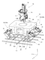
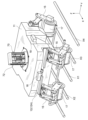
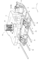
- FIG. 1 is a perspective view of a reinforcing bar binding device according to one embodiment.
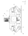
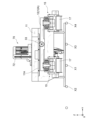
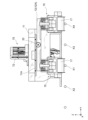
- FIG. 2 is a perspective view of a reinforcing bar binding device according to one embodiment.
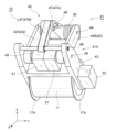
- FIG. 3 is a perspective view of the first unit.
- FIG. 4 is a front view of the leg.
- FIG. 5 is a perspective view of the leg.
- FIG. 6 is a side view of the leg.
- FIG. 7 is a side view of the leg.
- FIG. 8 is a side view of the leg.
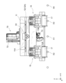
- FIG. 9 is a perspective view of a reinforcing bar binding device according to one embodiment.
- FIG. 10 is a perspective view of a reinforcing bar binding device according to one embodiment.
- FIG. 11A is a diagram showing the operation of the reinforcing bar binding device during a binding process.
- FIG. 11B is a diagram showing the operation of the reinforcing bar binding device during binding processing.
- FIG. 11C is a diagram showing the operation of the reinforcing bar binding device during binding processing.
- FIG. 12A is a diagram showing the operation of the reinforcing bar binding device during a binding process.
- FIG. 12B is a diagram showing the operation of the reinforcing bar binding device during binding processing.
- FIG. 12C is a diagram showing the operation of the reinforcing bar binding device during binding processing.
- FIG. 13 is a block diagram showing the control configuration of the reinforcing bar binding device according to one embodiment.
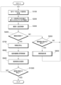
- FIG. 14 is a flow chart showing the process of the bundling process.
- FIG. 15 is a flowchart showing the process contents of the lateral movement process.
- FIG. 16A is a diagram showing the operation of the reinforcing bar binding device during a lateral movement process.
- FIG. 16B is a diagram showing the operation of the reinforcing bar binding device during a lateral movement process.
- FIG. 17A is a diagram showing the operation of the reinforcing bar binding device during a lateral movement process.
- FIG. 17B is a diagram showing the operation of the reinforcing bar binding device during a lateral movement process.
- FIG. 18A is a diagram showing the operation of the reinforcing bar binding device during a lateral movement process.
- FIG. 18B is a diagram showing the operation of the reinforcing bar binding device during a lateral movement process.
- FIG. 19A is a diagram showing the operation of the reinforcing bar binding device during a lateral movement process.
- FIG. 19B is a diagram showing the operation of the reinforcing bar binding device during a lateral movement process.
- FIG. 20A is a diagram showing the operation of the reinforcing bar binding device during a lateral movement process.
- FIG. 20B is a diagram showing the operation of the reinforcing bar binding device during a lateral movement process.
- FIG. 21A is a diagram showing the operation of the reinforcing bar binding device during a lateral movement process.
- FIG. 21B is a diagram showing the operation of the reinforcing bar binding device during a lateral movement process.
- the direction of travel of the reinforcing bar tying device is defined as the X-axis direction, the width direction of the reinforcing bar tying device as the Y-axis direction, and the height direction of the reinforcing bar tying device as the Z-axis direction.
- the reinforcing bar tying device of this embodiment is a self-propelled robot, and is a device that automatically performs tying processing of tying sections where reinforcing bars extending in the X-axis direction (hereinafter also referred to as "vertical bars”) and reinforcing bars extending in the Y-axis direction (hereinafter also referred to as "horizontal bars”) intersect during construction of a building, for example.
- vertical bars reinforcing bars extending in the X-axis direction
- horizontal bars reinforcing bars extending in the Y-axis direction
- the reinforcing bar tying device repeats traveling, stopping, and tying, performing tying processing on multiple tying sections.
- the reinforcing bar tying device reaches the end of the vertical bar in the X-axis direction, it performs lateral movement processing to move to the adjacent vertical bar in the Y-axis direction relative to the vertical bar it is traveling along.
- the rebar binding device completes the lateral movement process, it resumes traveling in the X-axis direction following the vertical bars, and performs the binding process on the binding portions on adjacent vertical bars in the Y-axis direction.
- the reinforcing bar binding device 10 of this embodiment has a main body 11, a leg structure 12 connected to the main body 11, and a support frame 13 connected to the main body 11.
- the support frame 13 is an example of a support part.
- the leg structure 12 includes a first unit 12A and a second unit 12B that are arranged in a pair in front of and behind the main body 11.
- the support frame 13 is arranged, for example, between the first unit 12A and the second unit 12B.
- the support frame 13 may be arranged in front of the first unit 12A (the front side in the traveling direction of the reinforcing bar binding device 10) or behind the second unit 12B (the rear side in the traveling direction of the reinforcing bar binding device 10).
- Each of the first unit 12A and the second unit 12B includes two legs 15.
- One of the legs 15 in the first unit 12A and one of the legs 15 in the second unit 12B are examples of third legs, and are arranged on one side of the main body 11 in the Y-axis direction.
- the other leg 15 of the first unit 12A and the other leg 15 of the second unit 12B are an example of a fourth leg and are provided on the other side of the Y-axis direction of the main body 11.
- the two legs 15 of the first unit 12A are an example of a first leg and are provided on one side of the X-axis direction of the main body 11 (the front side in the traveling direction of the reinforcing bar binding device 10).
- the two legs 15 of the second unit 12B are an example of a second leg and are provided on the other side of the X-axis direction of the main body 11 (the rear side in the traveling direction of the reinforcing bar binding device 10).
- the number of legs 15 of each of the first unit 12A and the second unit 12B may be one or three or more.
- Each leg 15 can perform an extension/retraction operation individually, and is configured to be able to adjust the height of the main body 11 through the extension/retraction operation of each leg 15.
- the support frame 13 has a frame shape extending along the Y-axis direction, and includes two first frame parts 13A extending in the Z-axis direction from the lower surface of the main body part 11, and a second frame part 13B extending in the Y-axis direction to connect the lower ends of the two first frame parts 13A.
- the dimension of the second frame part 13B in the Y-axis direction is configured to be, for example, about three times the distance between adjacent vertical bars in the Y-axis direction.
- the dimension of the second frame part 13B in the Y-axis direction may be configured to be, for example, about the same as the distance between adjacent vertical bars in the Y-axis direction.
- the second frame body portion 13B of the support frame 13 is placed so as to straddle the two vertical muscles X1, X3, including the vertical muscle X1 located in the center of the main body portion 11 in the Y-axis direction and the two vertical muscles X2, X3 located on either side of the vertical muscle X1 in the Y-axis direction, or the vertical muscles X1, X2.
- a sensor 16 is mounted on each side of the main body 11 in the X-axis direction.
- the sensor 16 is an example of a second detection unit. In the example shown in Figures 1 and 2, only the sensor 16 mounted on the front side of the main body 11 is shown.
- the sensor 16 has a detection range, for example, below the main body 11, which includes at least the vertical muscle X1 located in the center of the main body 11 in the Y-axis direction.
- the sensor 16 has a function of measuring the distance to an object, for example, and detects that the object is the vertical muscle X1 on the condition that the measured value of the distance to the object matches a distance preset as the distance to the vertical muscle X1.
- the two sensors 16 detect two points of the vertical muscle X1 separated in the X-axis direction, and identify the direction of the straight line connecting the two points detected by these sensors 16 as the longitudinal direction of the vertical muscle X1.
- the rebar binding device 10 then individually controls the rotational speed of the wheels 17 on both sides in the Y-axis direction so as to follow the longitudinal direction of the identified vertical muscle X1.
- the reinforcing bar binding device 10 moves to follow the vertical bar X1 while controlling the movement direction of the reinforcing bar binding device 10 so that it follows the longitudinal direction of the vertical bar X1 identified as described above.
- a sensor 18 is mounted on each side of the main body 11 in the Y-axis direction.
- the sensor 18 is an example of a first detection unit. In the example shown in Figures 1 and 2, only the sensor 18 mounted on one side of the main body 11 in the Y-axis direction is illustrated.
- the sensor 18 has a detection range, for example, below the main body 11, and the detection range includes at least the horizontal bar Y1 (see Figure 9, etc.) that crosses the main body 11 in the Y-axis direction when the rebar binding device 10 reaches the vicinity of the binding part.
- the sensor 18 has a function of measuring the distance to an object, for example, and detects that the object is the horizontal bar Y1 on the condition that the measured value of the distance to the object matches the distance to the horizontal bar Y1 that is preset.
- the two sensors 18 detect two points of the horizontal bar Y1 that are separated in the Y-axis direction, and when a horizontal bar is detected by these sensors 18, the direction in which the straight line connecting the two detected points extends is specified as the longitudinal direction of the horizontal bar.
- the reinforcing bar binding device 10 then calculates the location where the longitudinal direction of the vertical bars identified by the sensor 16 intersects with the longitudinal direction of the horizontal bars identified by the sensor 18 as the binding location where the vertical bars intersect with the horizontal bars.
- the reinforcing bar binding device 10 controls the rotational speed of the wheels 17 on both sides in the Y-axis direction individually to control the movement direction of the reinforcing bar binding device 10 so that the position of the calculated binding location coincides with the position of the binding part 73 of the binding mechanism 70 (described later) in the Y-axis direction.
- first unit 12A and the second unit 12B have a common configuration. Therefore, in the following explanation, the first unit 12A will be used as an example.
- the first unit 12A has, for example, a connecting portion 30 connected to the main body portion 11 and extending long in one direction, and legs 15 provided at the first and second longitudinal ends of the connecting portion 30.
- the connecting portion 30 has, for example, a substantially L-shaped cross section.
- the connecting portion 30 has, for example, a bottom plate portion 31 and a side plate portion 32 protruding from the bottom plate portion 31 in the Z-axis direction.
- the bottom plate portion 31 includes, for example, a first bottom plate portion 31A located on one side of the connecting portion 30 in the longitudinal direction, and a second bottom plate portion 31B located on the other side of the connecting portion 30 in the longitudinal direction.
- the side plate portion 32 extends, for example, over the entire longitudinal area of the connecting portion 30. That is, the connecting portion 30 may have a configuration in which the bottom plate portion 31 is cut out at the center portion in the longitudinal direction.
- a lateral movement roller 33 is provided at the center portion in the longitudinal direction of the side plate portion 32 of the connecting portion 30.
- the lateral movement roller 33 is an example of a drive gear and constitutes the second drive portion.
- the lateral movement roller 33 meshes with, for example, a drive rack 11A provided on the main body portion 11.
- the drive rack 11A is an example of an meshing portion and constitutes the second drive portion.
- the drive rack 11A has, for example, a plurality of teeth that mesh with the external teeth of the lateral movement roller 33, which are aligned linearly in the Y-axis direction.
- the lateral movement roller 33 may be provided on the main body portion 11, and the drive rack 11A may be provided on the connecting portion 30.
- the lateral movement roller 33 rotates based on the driving force from the motor constituting the second drive unit, the lateral movement roller 33 moves relative to the drive rack 11A along the longitudinal direction of the drive rack 11A, and the main body 11 and the first unit 12A may move relative to each other in the Y-axis direction.
- one leg 15 is connected to each of the first bottom plate portion 31A and the second bottom plate portion 31B of the connecting portion 30.
- the leg 15 has a base 40 (see FIG. 7, etc.) connected to the first bottom plate 31A or the second bottom plate 31B of the connecting portion 30.
- a displacement mechanism 41 is connected to the base 40.
- the displacement mechanism 41 is configured to be displaceable with a first end connected to the base 40 as a fixed end and a second end opposite to the first end as a free end.
- the displacement mechanism 41 has a link mechanism 41A that connects the wheel 17 and the main body 11.
- the link mechanism 41A is an example of a connecting portion and is configured to be expandable and contractible.
- the link mechanism 41A for example, has multiple links that extend long in one direction rotatably connected, and the multiple links include a first link 42 located at the first end and a second link 43 located at the second end.
- the first link 42 is connected to the second link 43 so as to be freely rotatable.
- the displacement mechanism 41 is provided on each leg 15 of the first unit 12A and the second unit 12B, and is configured to be independently controllable. That is, the first leg displacement mechanism 41 and the second leg displacement mechanism 41 are configured to be able to change the distance between the main body 11 and the vertical bars to different distances. Also, the third leg displacement mechanism 41 and the fourth leg displacement mechanism 41 are configured to be able to change the distance between the main body 11 and the vertical bars to different distances.
- the first link 42 includes a pair of link members 42A, 42B rotatably connected to both axial ends of a rotating shaft 44 provided at the tip of the base 40, and a restricting link mechanism 45 rotatably connected to an intermediate position of the pair of link members 42A, 42B in the axial direction of the rotating shaft 44, and restricts the displacement direction of the displacement mechanism 41.
- the pair of link members 42A, 42B have a shape that extends long in one direction, a first end is rotatably connected to the rotating shaft 44, and a second end is rotatably connected to a second rotating shaft 49 provided at the first end of the second link 43.
- the restricting link mechanism 45 is configured by rotatably connecting a plurality of restricting links 47 that extend long in one direction, and includes a first restricting link 47A connected to the tip of the base 40, and a second restricting link 47B that connects the first restricting link 47A and the second link 43.
- the first end of the first regulating link 47A is rotatably connected to the rotating shaft 44 provided at the tip of the base 40, and the second end of the first regulating link 47A is rotatably connected to the first end of the second regulating link 47B via the rotating shaft 48.
- the first end of the second regulating link 47B is rotatably connected to the second end of the first regulating link 47A via the rotating shaft 48, and the second end of the second regulating link 47B is rotatably connected to the first rotating shaft 46 provided at the first end of the second link 43.
- the rotating shaft 48 connecting the first regulating link 47A and the second regulating link 47B functions as a protrusion protruding from the connecting portion between the first regulating link 47A and the second regulating link 47B on both sides in the axial direction of the rotating shaft 48.
- An upward biasing force is applied to these protrusions by a coil spring 50 provided on the first link 42.
- the coil springs 50 are an example of a biasing member, and are provided in pairs on both sides of the first link 42 in the axial direction of the rotating shaft 48, sandwiching the restriction link mechanism 45 therebetween.
- the second link 43 supports both axial ends of the first rotating shaft 46 and the second rotating shaft 49.
- the first rotating shaft 46 and the second rotating shaft 49 are arranged in parallel in the longitudinal direction of the second link 43.
- the second end of the second regulating link 47B of the regulating link mechanism 45 is rotatably connected to the axial center of the first rotating shaft 46.
- the second ends of the pair of link members 42A, 42B of the first link 42 are rotatably connected to both axial ends of the second rotating shaft 49.
- a motor 51 that rotates the second rotating shaft 49 is provided in the axial center of the second rotating shaft 49.
- the motor 51 is an example of a first drive unit.
- the motor 51 is provided to correspond to each of the pair of link members 42A, 42B.
- the second link 43 has a bearing portion that is approximately U-shaped, and the bearing portion supports the wheel 17 so that it can rotate freely.
- the wheel 17 has a disk-shaped flange portion 17A on both sides in the width direction to prevent it from falling off the vertical bars X2, X3.
- a motor 52 that drives the wheel 17 to rotate is provided on the outer surface of the bearing portion.
- the reinforcing bar binding device 10 is provided with a motor 52 that corresponds individually to each of the four wheels 17, making it possible to control the rotation of each wheel 17 individually.
- the motor 52 may be built into each wheel 17.
- the second link 43 rotates relative to the first link 42 around the second rotating shaft 49 in conjunction with the rotation of the second rotating shaft 49.
- the second link 43 rotates in the clockwise direction shown in FIG. 8 around the second rotating shaft 49, and the second link 43 rotates relative to the first link 42 so that the angle at which the first link 42 and the second link 43 intersect increases.
- the displacement mechanism 41 is configured to be displaceable with the first end connected to the base 40 as a fixed end and the second end opposite the first end as a free end, so that the second rotating shaft 49 moves in the X-axis direction toward the base 40.
- the displacement direction of the wheel 17 provided at the tip of the displacement mechanism 41 is restricted by the restricting link mechanism 45. Therefore, when the motor 51 is driven, the wheel 17 at the tip of the displacement mechanism 41 rises or falls in the vertical direction.
- the main body 11 has a through-hole 60 that penetrates the main body 11 in the Z-axis direction.
- the through-hole 60 opens on the top surface of the main body 11, and the binding mechanism 70 is inserted from above.
- the binding mechanism 70 is cylindrical and includes a holding section 71, a lifting section 72 as an example of a lifting drive section, and a binding section 73.
- the holding section 71 is provided in the center of the longitudinal direction of the binding mechanism 70.
- the holding section 71 holds a roll of metal wire wound around it.
- the binding section 73 has a configuration in which two arms 73A, 73B cross in a roughly V-shape, and with the opposing directions of the two arms 73A, 73B aligned in a direction that crosses the binding site diagonally, the wire unwound from the holding section 71 is wound between one arm 73A and the other arm 73B to perform the binding process on the binding site using the wire.
- the bundling unit 73 performs bundling processing on the bundling area using wire by winding the wire around the bundling area, winding the wire wound around the bundling area so that it is tightly attached to the bundling area, and twisting the wire wound around the bundling area.
- the binding mechanism 70 has a disk-shaped engagement portion 74.
- the planar shape of the engagement portion 74 is larger than the opening shape of the through-hole 60. Therefore, when the binding mechanism 70 is inserted into the through-hole 60, the engagement portion 74 engages with the opening edge of the through-hole 60 in the Z-axis direction to position the binding mechanism 70.
- the binding mechanism 70 has a binding portion 73 provided on one side in the longitudinal direction based on the engagement portion 74 (in this example, the lower side).
- the binding mechanism 70 includes a lifting unit 72 that raises and lowers the binding part 73 in the Z-axis direction.
- the lifting unit 72 raises and lowers the binding part 73 in the Z-axis direction, so that the binding part 73 is accurately lowered to the binding location, and the binding process using the wire is performed accurately on the binding location.
- the binding portion 73 of the binding mechanism 70 protrudes downward from the underside of the main body 11.
- the rebar binding device 10 then runs following the vertical bar X1.
- the binding portion 73 of the binding mechanism 70 is positioned above and spaced apart from the vertical bar X1.
- the two arm portions 73A, 73B of the binding portion 73 face each other in a direction that intersects obliquely with the longitudinal direction of the vertical bar X1.
- the rebar binding device 10 travels following the vertical bar X1, and when the rebar binding device 10 reaches a position facing the horizontal bar in the Z-axis direction, the binding part 73 of the binding mechanism 70 is lowered to a position where the distance from the vertical or horizontal bar is a predetermined distance with the extension and contraction of each leg 15 of the main body 11, and the binding part 73 of the binding mechanism 70 is aligned with the binding part in the Z-axis direction.
- the two arms 73A and 73B of the binding part 73 face each other in a direction that crosses the binding part diagonally.
- the binding part 73 wraps the wire from one arm 73A to the other arm 73B, thereby performing the binding process of the binding part using the wire.
- the binding mechanism 70 When inserted into the through-hole 60, the binding mechanism 70 is configured to be rotatable in the circumferential direction about a rotation axis passing through the center of the opening of the through-hole 60. In this case, the binding mechanism 70 may be rotated manually or may be rotated based on a driving force from a motor, which is an example of a rotation drive unit. When the binding mechanism 70 rotates in the circumferential direction about the rotation axis, the orientation of the two arm portions 73A, 73B of the binding portion 73 is changed. Therefore, the binding mechanism 70 can use the wire to perform the binding process on the binding portion not only when the vertical and horizontal bars intersect at right angles, but also when the vertical and horizontal bars intersect diagonally.
- control device 100 of the rebar binding device 10 is realized by, for example, a hardware processor such as a CPU (Central Processing Unit) executing a program (software).
- a hardware processor such as a CPU (Central Processing Unit) executing a program (software).
- some or all of these components may be realized by hardware (including circuitry) such as an LSI (Large Scale Integration), ASIC (Application Specific Integrated Circuit), FPGA (Field-Programmable Gate Array), or GPU (Graphics Processing Unit), or may be realized by a combination of software and hardware.
- LSI Large Scale Integration
- ASIC Application Specific Integrated Circuit
- FPGA Field-Programmable Gate Array
- GPU Graphics Processing Unit
- the program may be stored in advance in a computer-readable recording device such as the HDD or flash memory of the control device 100, or may be stored in a removable computer-readable recording medium such as a DVD or CD-ROM, and installed in the HDD or flash memory of the control device 100 by attaching the computer-readable recording medium to a drive device.
- a computer-readable recording device such as the HDD or flash memory of the control device 100
- a removable computer-readable recording medium such as a DVD or CD-ROM
- the control device 100 includes, for example, a position information acquisition unit 110, an attitude information acquisition unit 160, a tracking control unit 120, a stop control unit 130, a lateral movement control unit 140, an elevation control unit 150, a horizontal control unit 170, and a motor control unit 180.
- the position information acquisition unit 110 acquires information about the position of the reinforcing bar binding device 10 based on information acquired from the camera group 200.
- the camera group 200 includes, for example, sensors 16 provided on both sides of the reinforcing bar binding device 10 in the X-axis direction, and sensors 18 provided on both sides of the reinforcing bar binding device 10 in the Y-axis direction.
- the information about the position of the reinforcing bar binding device 10 includes, for example, information about the longitudinal direction of the vertical bars identified by the camera group 200, and information about the longitudinal direction of the horizontal bars.
- the tracking control unit 120 controls the running of the reinforcing bar binding device 10 so that it follows the vertical bars, based on information about the position of the reinforcing bar binding device 10 acquired by the position information acquisition unit 110. For example, based on information about the longitudinal direction of the vertical bars acquired by the position information acquisition unit 110, the tracking control unit 120 controls the running of the reinforcing bar binding device 10 so that the moving direction of the reinforcing bar binding device 10 coincides with the longitudinal direction of the vertical bars. For example, the tracking control unit 120 determines the control amount of the motor group 230 by the motor control unit 180 so that the moving direction of the reinforcing bar binding device 10 coincides with the longitudinal direction of the vertical bars. In this case, the motor group 230 includes, for example, a motor 52 that controls the rotation of each wheel 17. The tracking control unit 120 measures the load of the motor 52 that is driven when the reinforcing bar binding device 10 moves along the longitudinal direction of the vertical bars.
- the tracking control unit 120 drives the motor 51 that controls the extension and contraction movement of each leg 15 of the multiple legs 15 constituting the leg structure 12, so that the leg 15 located in front of the reinforcing bar binding device 10, among the multiple legs 15 constituting the leg structure 12, is positioned in front of the reinforcing bar binding device 10 in the displacement mechanism 41, with the connection portion between the first link 42 located at the first end and the second link 43 located at the second end being positioned in front of the reinforcing bar binding device 10.
- the tracking control unit 120 determines whether the reinforcing bar binding device 10 has collided with an obstacle based on the change in the load of the motor that moves the reinforcing bar binding device 10 forward.
- the tracking control unit 120 is an example of a first determination unit.
- the stop control unit 130 controls the travel of the rebar tying device 10 to stop it at the binding portion where the vertical and horizontal bars intersect, based on information about the position of the rebar tying device 10 acquired by the position information acquisition unit 110.
- the stop control unit 130 identifies the position where the longitudinal direction of the vertical bar and the longitudinal direction of the horizontal bar intersect, identified by the camera group 200, as the binding portion where the vertical and horizontal bars intersect, and stops the movement of the rebar tying device 10 at the position of the identified binding portion.
- the stop control unit 130 determines the amount of control of the motor group 230 by the motor control unit 180, for example, so that the movement of the rebar tying device 10 is stopped at the binding portion where the vertical and horizontal bars intersect.
- the motor group 230 includes, for example, the motor 52 that controls the rotation of each wheel 17.
- the lateral movement control unit 140 is an example of a control unit, and for example, controls the lateral movement of the reinforcing bar binding device 10 based on information on the position of the reinforcing bar binding device 10 acquired by the position information acquisition unit 110.
- the lateral movement control unit 140 is an example of a movement amount calculation unit, and for example, calculates the amount of lateral movement of the main body unit 11 based on information on the position of the reinforcing bar binding device 10 acquired by the position information acquisition unit 110.
- the lateral movement control unit 140 detects that the reinforcing bar binding device 10 has reached the longitudinal end of a vertical bar based on information on the position of the reinforcing bar binding device 10 acquired by the position information acquisition unit 110, it executes a lateral movement process of the reinforcing bar binding device 10 so as to change the vertical bar on which each wheel 17 of the reinforcing bar binding device 10 is placed to an adjacent vertical bar in the Y-axis direction.
- the lateral movement control unit 140 determines the amount of control of the motor group 230 by the motor control unit 180 at each step of the lateral movement process.
- the motor group 230 includes, for example, a motor 52 that controls the rotation of each wheel 17, a motor 51 that controls the extension and retraction movement of each leg 15, and a motor that moves the main body 11 and leg structure 12 laterally.
- the lateral movement control unit 140 measures the load of the motor that drives the lateral movement rollers 33 when the reinforcing bar binding device 10 moves to adjacent vertical bars in the Y-axis direction, and judges whether the lateral movement process of the reinforcing bar binding device 10 is performed normally or not based on the change in the measured motor load.
- the lateral movement control unit 140 is an example of a second judgment unit. For example, if the measured motor load is equal to or greater than a predetermined threshold, the lateral movement control unit 140 judges that the lateral movement process of the reinforcing bar binding device 10 is not performed normally, such as when the wheels 17 provided at the tips of the legs 15 collide with the vertical bars X2 and X3.
- the lateral movement control unit 140 judges that the lateral movement process of the reinforcing bar binding device 10 is not performed normally, it controls the drive of the motors 51 that extend and retract each leg 15 so as to move the wheels 17 away from the vertical bars X2 and X3.
- the lifting control unit 150 controls the lifting and lowering operation of the binding part 73 of the binding mechanism 70 based on information about the position of the rebar binding device 10 acquired by the position information acquisition unit 110. For example, when the rebar binding device 10 reaches a binding portion where vertical and horizontal bars intersect, the lifting control unit 150 controls the lifting and lowering operation of the binding mechanism 70 so as to lower the binding part 73 of the binding mechanism 70. For example, the lifting control unit 150 determines the control amount of the motor group 230 by the motor control unit 180 so as to lower the binding part 73 of the binding mechanism 70. In this case, the motor group 230 includes a motor that lifts and lowers the binding part 73 of the binding mechanism 70.
- the posture information acquisition unit 160 acquires information about the posture of the reinforcing bar binding device 10 based on information acquired from the sensor group 210 and the motor group 230.
- the posture information acquisition unit 160 acquires, for example, information about the motor load of the motor that controls the extension and retraction movement of each leg 15 as information about the posture of the reinforcing bar binding device 10, and identifies the horizontal level of the main body 11 based on the acquired information about the motor load.
- the sensor group 210 includes, for example, a sensor that measures the motor load of the motor that controls the extension and retraction movement of each leg 15 and an inclination detection sensor such as a gyro sensor that detects the inclination of the posture of the reinforcing bar binding device 10.
- the motor group 230 also includes, for example, a motor 51 that controls the extension and retraction movement of each leg 15.
- the horizontal control unit 170 is an example of a control unit, and controls the attitude of the rebar binding device 10 to maintain a horizontal attitude, for example, based on information about the attitude of the rebar binding device 10 acquired by the attitude information acquisition unit 160.
- the horizontal control unit 170 measures, for example, the motor load of the motors 51 that control the extension and retraction movement of each leg 15, and determines the control amount of the motor group 230 by the motor control unit 180 so that the total value of the measured motor loads of the motors 51 is minimized.
- the motor group 230 includes the motors 51 that control the extension and retraction movement of each leg 15.
- FIG. 14 is a flowchart showing an example of the binding process.
- the flowchart shown in FIG. 14 is executed, for example, when the operation of the reinforcing bar binding device 10 is started.
- control device 100 first measures the motor load of the motor 51 that extends and retracts each leg 15 of the leg structure 12 (step S100).
- control device 100 sets the drive amount of the motors 51 that extend and retract each leg 15 so that the total motor load of each motor measured in the previous step S100 is minimized, and controls the rebar binding device 10 to maintain a horizontal position (step S200).
- control device 100 identifies the longitudinal direction of the vertical bar X1 using the sensors 16 provided on both sides of the main body 11 in the X-axis direction, and sets the drive amount of the motor 52 that rotates each wheel 17 based on the identified longitudinal direction of the vertical bar X1, and causes the rebar binding device 10 to travel following the vertical bar X1 (step S300).
- control device 100 determines whether or not a horizontal line has been detected by the sensors 18 provided on both sides of the main body 11 in the Y-axis direction (step S400).
- step S500 determines whether or not the conditions for horizontal movement are met.
- the conditions for horizontal movement are met, for example, when the reinforcing bar binding device 10 reaches the end of the vertical bar X1 in the X-axis direction, or when an obstacle is detected ahead in the direction of travel of the reinforcing bar binding device 10.
- step S500 NO
- step S500 YES
- the control device 100 first drives the lateral movement rollers 33 in the forward direction, which is the first drive direction, and moves the main body 11 in the Y-axis direction relative to the leg structure 12 while supporting the leg structure 12 by abutting each leg 15 constituting the leg structure 12 against the vertical bar X1 (step S601).
- control device 100 determines whether the drive amount of the lateral movement roller 33 that was driven in the forward direction in the previous step S601 has reached the first threshold value (step S602).
- step S602 NO
- step S602 YES
- control device 100 determines whether each leg 15 has moved away from the vertical muscles X2, X3 (whether the support frame 13 has come into contact with the vertical muscles X1, X3) based on the drive amount of the motor 51 that extends and retracts each leg 15 constituting the leg structure 12 (step S604).
- step S604 NO
- step S604 YES
- control device 100 determines whether the drive amount of the lateral movement roller 33 that was driven in the reverse direction in the previous step S605 has reached a second threshold value (step S606).
- step S606 NO
- step S606 YES
- control device 100 determines whether the support frame 13 connected to the main body 11 has moved away from the vertical muscles X1, X3 (whether each leg 15 has come into contact with the vertical muscles X1, X4) based on the drive amount of the motor 51 that extends and retracts each leg 15 constituting the leg structure 12 (step S608).
- it drives the lateral movement rollers 33 in the forward direction to move the main body 11 in the Y-axis direction relative to the leg structure 12 while supporting the leg structure 12 by bringing the legs 15 constituting the leg structure 12 into contact with the vertical muscles X1, X4 (step S609).
- control device 100 determines whether the drive amount of the lateral movement roller 33 that was driven in the forward direction in the previous step S609 has reached a third threshold value (step S610).
- step S610 NO
- control device 100 if the control device 100 has executed the lateral movement process of the rebar binding device 10 in the previous step S600, it returns the process to step S100.
- control device 100 controls the lifting unit 72 that raises and lowers the binding unit 73 of the binding mechanism 70 relative to the main body 11, and adjusts the position of the binding unit 73 of the binding mechanism 70 in the Z-axis direction relative to the binding portion where the vertical muscle X3 and the horizontal muscle Y1 intersect (step S800).
- control device 100 controls the operation of the binding mechanism 70, whose position in the Z-axis direction has been controlled, to bind the binding portion (step S900).
- step S1000 determines whether the operation of the reinforcing bar binding device 10 has stopped.
- the rebar binding device 10 has the wheels 17 of each leg 15 constituting the leg structure 12 placed on the vertical bars X2 and X3, and the leg structure 12 is supported by the vertical bars X2 and X3.
- the support frame 13 connected to the main body 11 is spaced upward from the vertical bars X1 and X3.
- the reinforcing bar binding device 10 when the reinforcing bar binding device 10 performs the lateral movement process, it first detects the position of the vertical bar X4 adjacent in the Y-axis direction to the vertical bar X3 along which the reinforcing bar binding device 10 is running, using the sensors 18 provided on both sides of the main body 11 in the Y-axis direction. The reinforcing bar binding device 10 then measures the distance in the Y-axis direction between the vertical bar X3 on which the wheels 17 of each leg 15 constituting the leg structure 12 are placed and the vertical bar X4 detected as described above. Based on the measured distance, the reinforcing bar binding device 10 determines the amount of movement in the Y-axis direction of the main body 11 or the leg structure 12 in each process described below.
- the reinforcing bar binding device 10 may also first calculate the position of the vertical bar X4 adjacent in the Y-axis direction to the vertical bar X3 along which the reinforcing bar binding device 10 is running, using the sensors 18 provided on both sides of the main body 11 in the Y-axis direction.
- the amount of movement of the main body 11 or the leg structure 12 in the Y-axis direction is calculated based on information on the distance in the Y-axis direction from the center position of the reinforcing bar binding device 10 (the position of the binding mechanism 70, the position of the vertical bar X1 detected by the sensor 16) to the position of the sensor 18, and information on the distance in the Y-axis direction from the position of the sensor 18 to the position of the vertical bar X3.
- the reinforcing bar binding device 10 controls the amount of movement of the main body 11 or the leg structure 12 in the Y-axis direction in each process described later to be "80".
- the rebar binding device 10 controls the movement amount of the main body 11 or leg structure 12 in the Y-axis direction in each process described below to be "120".
- information on the distance in the Y-axis direction from the center position of the rebar binding device 10 to the position of the sensor 18 may be stored in memory in advance as initial information.
- Information on the distance in the Y-axis direction from the position of the sensor 18 to the position of the vertical bar X3 may be calculated from the position of the vertical bar X3 detected by the sensor 18.
- the rebar binding device 10 first drives the lateral movement rollers 33 in the forward direction, and moves the main body 11 in the Y-axis direction relative to the leg structure 12 while supporting the leg structure 12 by bringing each leg 15 constituting the leg structure 12 into contact with the vertical bars X2 and X3.
- the main body 11 approaches the vertical bar X4 that is adjacent in the Y-axis direction to the vertical bar X3 on which the leg 15 is placed.
- the reinforcing bar binding device 10 contracts each leg 15 constituting the leg structure 12, lowering the height of the main body 11 relative to the vertical bars X1 and X3. Then, the reinforcing bar binding device 10 abuts the support frame 13 connected to the main body 11 against the vertical bars X1 and X3. In this case, the support frame 13 is placed so as to straddle two vertical bars X1 and X3, including the vertical bar X1 along which the reinforcing bar binding device 10 runs and the vertical bar X3 adjacent to the vertical bar X1 in the Y-axis direction.
- each leg 15 constituting the leg structure 12 from a state in which the support frame 13 abuts against the vertical bars X1 and X3
- each leg 15 moves away from the vertical bars X2 and X3 (corresponding to the first process).
- the rebar binding device 10 reverses the lateral movement rollers 33 to move the leg structure 12 in the Y-axis direction relative to the main body 11 while the support frame 13 abuts against the vertical bars X3 and X4 to support the main body 11 (corresponding to the second process).
- each leg 15 constituting the leg structure 12 is positioned to face the vertical bars X1 and X4 in the Z-axis direction.
- the rebar binding device 10 extends each leg 15 constituting the leg structure 12, and abuts each leg 15 against the vertical bars X1, X4 (corresponding to the third process). Then, when the rebar binding device 10 further extends each leg 15 constituting the leg structure 12 from the state in which each leg 15 abuts against the vertical bars X1, X4, the support frame 13 connected to the main body 11 moves upward away from the vertical bars X3, X4.
- the rebar binding device 10 drives the lateral movement rollers 33 in the forward direction, and moves the main body 11 in the Y-axis direction relative to the leg structure 12 while supporting the leg structure 12 by bringing each leg 15 constituting the leg structure 12 into contact with the vertical bars X1 and X4 (corresponding to the fourth process). This returns the relative positions of the main body 11 and the leg structure 12 in the Y-axis direction to their initial states.
- the reinforcing bar binding device 10 of this embodiment repeats a process of moving the leg structure 12 in the Y-axis direction relative to the main body 11 while the support frame 13 is abutting against the vertical bars X1, X3 or the vertical bars X3, X4 to support the main body 11, and a process of moving the main body 11 in the Y-axis direction relative to the leg structure 12 while the leg structure 12 is abutting against the vertical bars X2, X3 or the vertical bars X1, X4 to support the leg structure 12.
- the reinforcing bar binding device 10 can move in the Y-axis direction efficiently by moving in stages in the Y-axis direction.
- the reinforcing bar binding device 10 can lighten the weight of the object moved in one movement and reduce the driving load of the lateral movement rollers 33 by moving in stages in the Y-axis direction.
- the rebar binding device 10 by moving the rebar binding device 10 in the Y-axis direction in stages, the generation of rotational moment with the legs 15 supported by the vertical bars X2 and X3 or the vertical bars X1 and X4 as fulcrums is suppressed compared to when the movement in the Y-axis direction is performed all at once, and the lateral movement process can be performed stably.
- each leg 15 constituting the leg structure 12 has a restricting link mechanism 45 that restricts the movement direction of the wheel 17. Therefore, the wheel 17 can be stably moved in a direction approaching or moving away from the vertical bars X2, X3 or the vertical bars X1, X4. Therefore, the reinforcing bar binding device 10 is prevented from accidentally colliding with the vertical bars X2, X3 or the vertical bars X1, X4 when the wheel 17 moves in the Y-axis direction away from the vertical bars X2, X3 or the vertical bars X1, X4, and the lateral movement process of the reinforcing bar binding device 10 can be stably performed.
- the reinforcing bar binding device 10 when performing the lateral movement process, if the reinforcing bar binding device 10 detects that the wheel 17 has collided with the vertical bars X2, X3 or the vertical bars X1, X4 based on the motor load of the motor driving the lateral movement rollers 33, it further drives the lateral movement rollers 33 in the direction to move the wheel 17 away from the vertical bars X2, X3 in the Y-axis direction. This allows the reinforcing bar binding device 10 to perform the lateral movement process even more stably.
- the leg 15 that is located in front of the reinforcing bar binding device 10 among the multiple legs 15 that make up the leg structure 12 drives the motor 51 that controls the extension and contraction movement of each leg 15 so that the connection part between the first link 42 located at the first end and the second link 43 located at the second end is positioned in front of the reinforcing bar binding device 10 in the displacement mechanism 41.
- the reinforcing bar binding device 10 judges whether the reinforcing bar binding device 10 has collided with an obstacle based on the change in the load of the motor that moves the reinforcing bar binding device 10 forward. Therefore, the reinforcing bar binding device 10 can judge whether the reinforcing bar binding device 10 has collided with an obstacle when moving forward without providing a new sensor.
- the reinforcing bar binding device 10 drives a motor 51 that controls the extension and contraction movement of the leg 15 so that, when the reinforcing bar binding device 10 accelerates or decelerates forward, the leg 15 that is located in front of the reinforcing bar binding device 10 among the multiple legs 15 that make up the leg structure 12 is positioned such that the connection portion between the first link 42 located at the first end and the second link 43 located at the second end of the multiple links that make up the displacement mechanism 41 is positioned in front of the reinforcing bar binding device 10 in the displacement mechanism 41.
- the reinforcing bar binding device 10 drives a motor 51 that controls the extension and contraction movement of the leg 15 so that, when the reinforcing bar binding device 10 accelerates or decelerates forward, the leg 15 that is located in front of the reinforcing bar binding device 10 among the multiple legs 15 that make up the leg structure 12 is positioned such that the connection portion between the first link 42 located at the first end and the second link 43 located at the second end of the multiple links that make up the displacement mechanism 41 is positioned in front of the reinforcing bar binding device 10 in the displacement mechanism 41. Therefore, when the rebar binding device 10 accelerates or decelerates forward, the height of the main body 11 can be prevented from fluctuating due to the extension and contraction of each leg 15 that constitutes the leg structure 12.
- the coil spring 50 applies a biasing force in a direction that extends the legs 15 and moves the wheels 17 closer to the vertical bars X1, X2, and X3. Therefore, even if the center of gravity of the main body 11 moves up and down as the wire used for binding is consumed as the reinforcing bar binding process progresses, the biasing force from the coil spring 50 acts in response to the movement of the center of gravity of the main body 11, so the main body 11 can maintain the desired position and the reinforcing bars can be bound accurately.
- the rebar binding device 10 applies a biasing force from the coil spring 50 in the direction that extends the legs 15, thereby reducing the power consumption when driving the motor 51 in the direction that extends the legs 15 to support the weight of the main body 11 by the amount of the biasing force of the coil spring 50.
- the power consumption when the rebar binding device 10 performs horizontal control can be further reduced.
- the binding mechanism 70 is inserted into the through-hole 60 provided in the main body 11, and the binding mechanism 70 is configured to be rotatable in the circumferential direction around the center of the opening of the through-hole 60 relative to the main body 11. Therefore, when performing binding processing on a binding portion where vertical and horizontal bars intersect, the reinforcing bar tying device 10 is configured to be able to change the orientation of the two arm portions of the binding portion 73 of the binding mechanism 70. Therefore, the reinforcing bar tying device 10 can use wires to perform binding processing on a binding portion not only when the vertical and horizontal bars intersect at right angles, but also when the vertical and horizontal bars intersect diagonally, and can perform binding processing with high versatility.
- the reinforcing bar binding device 10 performs the lateral movement process when moving to the vertical bar X4 adjacent to the vertical bar X3 on which the leg 15 is supported.
- the reinforcing bar binding device 10 may perform the lateral movement process in other ways. For example, when the reinforcing bar binding device 10 reaches the binding portion, if the position of the binding portion 73 of the binding mechanism 70 does not match the position of the binding portion in the Y-axis direction, the position of the binding mechanism 70 may be fine-tuned in the Y-axis direction in the same manner as the above-mentioned lateral movement process.
- the reinforcing bar binding device 10 may fine-tune the position of the binding mechanism 70 in the Y-axis direction by repeating the process of moving the leg structure 12 in the Y-axis direction relative to the main body 11 with the support frame 13 abutting against the vertical bars X1 and X3 to support the main body 11, and the process of moving the main body 11 in the Y-axis direction relative to the leg structure 12 with the leg structure 12 abutting against the vertical bars X2 and X3 to support the leg structure 12.
- a binding mechanism configured to be able to bind a binding portion where a reinforcing bar extending in a first direction and a reinforcing bar extending in a second direction intersect;
- a leg portion configured to be capable of running on a reinforcing bar extending in the first direction;
- a first drive unit configured to be able to separate the leg portion from the reinforcing bar;
- a second drive unit configured to be able to move the leg in a second direction intersecting the first direction;
- a control unit that controls the first driving unit and the second driving unit; Equipped with The control unit controls the first driving unit to move the leg away from the reinforcing bar, and controls the second driving unit to move the leg in the second direction.
- [Appendix 2] a support portion coupled to the body portion, The leg portion is connected to the main body portion so as to be movable in the second direction,
- the control unit is A first process of controlling the first driving unit, and when the reinforcing bar on which the leg portion is supported is a first reinforcing bar, moving the leg portion away from the first reinforcing bar while keeping the supporting portion in contact with the first reinforcing bar;
- control unit repeats the first process and the second process a plurality of times to cause the leg portion to face the second reinforcing bar in the height direction of the main body portion. 3.
- the second drive unit includes a rail-shaped meshing portion provided on one side of the main body unit and the leg unit, and a drive gear provided on the other side and meshing with the meshing portion,
- the control unit drives the drive gear in a first drive direction with the drive gear meshed with the meshing portion
- the control unit drives the drive gear in a second drive direction with the drive gear meshed with the meshing portion.
- the control unit determines whether or not the leg has been separated from the reinforcing bar based on whether or not a drive amount of the first drive unit has reached a predetermined threshold value. 6.
- a rebar binding device according to any one of claims 1 to 5.
- the reinforcing bar binding device further includes a first detection unit that detects a reinforcing bar adjacent to the reinforcing bar in a second direction when the reinforcing bar binding device moves the reinforcing bar extending in the first direction, The control unit determines a distance to move the leg in the second direction based on a detection result of the reinforcing bar by the first detection unit. 7.
- a rebar binding device according to any one of claims 1 to 6.
- a second detection unit is further provided for calculating the binding portion, The control unit adjusts the amount of movement of the reinforcing bar binding device in the second direction when the reinforcing bar binding device moves toward the binding portion based on the position of the reinforcing bar detected by the second detection unit when the reinforcing bar binding device moves to the adjacent reinforcing bar in the second direction.
- a rebar binding device according to any one of claims 1 to 7.
- [Appendix 9] a support portion coupled to the body portion,
- the first drive unit is configured to be able to extend and retract the leg unit,
- the control unit is When the first drive unit is controlled to extend the leg, the leg abuts against the reinforcing bar and the support portion moves away from the reinforcing bar, When the first drive unit is controlled to contract the leg portion, the support portion abuts against the reinforcing bar and the leg portion moves away from the reinforcing bar.
- a binding mechanism configured to be able to bind a portion where a reinforcing bar extending in a first direction and a reinforcing bar extending in a second direction intersect; A main body portion on which the binding mechanism is mounted; A detection unit that detects the reinforcing bar adjacent to the main body in the second direction; a moving mechanism that moves the main body in the second direction; Equipped with The movement mechanism has a movement amount calculation unit that calculates a movement amount of the main body part in the second direction based on the position of the reinforcing bar detected by the detection unit. Rebar tying device.
- the rebar binding device disclosed herein can perform precise lateral movement.
Landscapes
- Engineering & Computer Science (AREA)
- Mechanical Engineering (AREA)
- Architecture (AREA)
- Robotics (AREA)
- Civil Engineering (AREA)
- Structural Engineering (AREA)
- Chemical & Material Sciences (AREA)
- Combustion & Propulsion (AREA)
- Transportation (AREA)
- Human Computer Interaction (AREA)
- Wire Processing (AREA)
- Reinforcement Elements For Buildings (AREA)
- Basic Packing Technique (AREA)
- Manipulator (AREA)
Abstract
Description
上記実施形態から把握できる技術的思想を以下に記載する。
第1方向に延びる鉄筋と第2方向に延びる鉄筋とが交差する結束部位を結束可能に構成された結束機構と、
前記結束機構を搭載した本体部と、
前記第1方向に延びる鉄筋上を走行可能に構成された脚部と、
前記脚部を前記鉄筋から離間可能に構成された第1駆動部と、
前記第1方向と交差する第2方向に前記脚部を移動可能に構成された第2駆動部と、
前記第1駆動部及び前記第2駆動部を制御する制御部と、
を備え、
前記制御部は、前記第1駆動部を制御して前記脚部を前記鉄筋から離間させた状態で、前記第2駆動部を制御して前記第2方向に前記脚部を移動させる、
鉄筋結束装置。
前記本体部に対して連結された支持部をさらに備え、
前記脚部は、前記本体部に対して前記第2方向に移動可能に連結され、
前記制御部は、
前記第1駆動部を制御し、前記脚部が支持された鉄筋を第1鉄筋とするとき、前記第1鉄筋に対して前記支持部を当接させた状態で、前記第1鉄筋から前記脚部を離間させる第1処理と、
前記第2駆動部を制御し、前記第1鉄筋から離間した前記脚部を前記本体部に対して前記第2方向に移動させる第2処理と、
前記第1駆動部を制御し、前記脚部を前記第1鉄筋に対して前記第2方向において隣り合う第2鉄筋に対して当接させる第3処理と、
前記本体部を前記脚部に対して前記第2方向に移動させる第4処理と、
を実行する、
付記1に記載の鉄筋結束装置。
前記制御部は、前記第1処理と前記第2処理とを複数回に亘って繰り返し、前記脚部を前記第2鉄筋に対して前記本体部の高さ方向において対向させる、
付記2に記載の鉄筋結束装置。
前記制御部は、前記第1処理と前記第2処理とを複数回に亘って繰り返す際、前記脚部を各回において同程度の距離だけ前記第2方向に移動させる、
付記3に記載の鉄筋結束装置。
前記第2駆動部は、前記本体部及び前記脚部のうち、一方側に設けられるレール状の噛合部と、他方側に設けられ、前記噛合部に噛み合う駆動歯車とを含み、
前記制御部は、前記本体部を前記脚部に対して前記第2方向に移動させる際には、前記駆動歯車を前記噛合部に噛み合わせた状態で前記駆動歯車を第1駆動方向に駆動させ、前記脚部を前記本体部に対して前記第2方向に移動させる際には、前記駆動歯車を前記噛合部に噛み合わせた状態で前記駆動歯車を第2駆動方向に駆動させる、
付記1から4のいずれか一つに記載の鉄筋結束装置。
前記制御部は、前記第1駆動部の駆動量が所定の閾値に達したか否かに基づいて、前記脚部が前記鉄筋から離間したか否かを判定する、
付記1から5のいずれか一つに記載の鉄筋結束装置。
前記鉄筋結束装置が前記第1方向に延びる鉄筋を移動している際、当該鉄筋に対して第2方向において隣り合う鉄筋を検知する第1検知部をさらに備え、
前記制御部は、前記第1検知部による鉄筋の検知結果に基づいて、前記脚部を前記第2方向に移動させる距離を決定する、
付記1から6のいずれか一つに記載の鉄筋結束装置。
前記結束部位をの算出に用いる第2検知部をさらに備え、
前記制御部は、前記鉄筋結束装置が前記第2方向において隣り合う鉄筋に移動した際、前記第2検知部により検知された鉄筋の位置に基づいて、前記鉄筋結束装置が前記結束部位に向けて移動する際の前記第2方向の移動量を調整する、
付記1から7のいずれか一つに記載の鉄筋結束装置。
前記本体部に対して連結された支持部をさらに備え、
前記第1駆動部は、前記脚部を伸縮可能に構成され、
前記制御部は、
前記第1駆動部を制御し、前記脚部を伸長させた場合、前記脚部が前記鉄筋に当接して前記支持部が前記鉄筋から離間し、
前記第1駆動部を制御し、前記脚部を収縮させた場合、前記支持部が前記鉄筋に当接して前記脚部が前記鉄筋から離間する、
付記1から8のいずれか一つに記載の鉄筋結束装置。
第1方向に延びる鉄筋と第2方向に延びる鉄筋とが交差する部位を結束可能に構成された結束機構と、
前記結束機構を搭載した本体部と、
前記本体部に対して前記第2方向において隣り合う前記鉄筋を検知する検知部と、
前記本体部を前記第2方向に移動させる移動機構と、
を備え、
前記移動機構は、前記検知部により検知された前記鉄筋の位置に基づいて、前記本体部の前記第2方向への移動量を算出する移動量算出部を有する、
鉄筋結束装置。
11…本体部
12…脚構造
12A…第1ユニット
12B…第2ユニット
13…支持フレーム
15…脚部
17…車輪
33…横移動ローラ
51…モータ
52…モータ
70…結束機構
71…保持部
72…昇降部
73…結束部
100…制御装置
110…位置情報取得部
120…追従制御部
130…停止制御部
140…横移動制御部
150…昇降制御部
160…姿勢情報取得部
170…水平制御部
180…モータ制御部
X1,X2,X3,X4…縦筋
Y1…横筋
Claims (10)
- 第1方向に延びる鉄筋と第2方向に延びる鉄筋とが交差する結束部位を結束可能に構成された結束機構と、
前記結束機構を搭載した本体部と、
前記第1方向に延びる鉄筋上を走行可能に構成された脚部と、
前記脚部を前記鉄筋から離間可能に構成された第1駆動部と、
前記本体部に対して前記第1方向と交差する前記第2方向に前記脚部を移動可能に構成された第2駆動部と、
前記第1駆動部及び前記第2駆動部を制御する制御部と、
を備え、
前記制御部は、前記第1駆動部を制御して前記脚部を前記鉄筋から離間させた状態で、前記第2駆動部を制御して前記第2方向に前記脚部を移動させる、
鉄筋結束装置。 - 前記本体部に対して連結された支持部をさらに備え、
前記脚部は、前記本体部に対して前記第2方向に移動可能に連結され、
前記制御部は、
前記第1駆動部を制御し、前記脚部が支持された鉄筋を第1鉄筋とするとき、前記第1鉄筋に対して前記支持部を当接させた状態で、前記第1鉄筋から前記脚部を離間させる第1処理と、
前記第2駆動部を制御し、前記第1鉄筋から離間した前記脚部を前記本体部に対して前記第2方向に移動させる第2処理と、
前記第1駆動部を制御し、前記脚部を前記第1鉄筋に対して前記第2方向において隣り合う第2鉄筋に対して当接させる第3処理と、
前記本体部を前記脚部に対して前記第2方向に移動させる第4処理と、
を実行する、
請求項1に記載の鉄筋結束装置。 - 前記制御部は、前記第2処理と前記第4処理とを複数回に亘って繰り返し、前記脚部を前記第2鉄筋に対して前記本体部の高さ方向において対向させる、
請求項2に記載の鉄筋結束装置。 - 前記制御部は、前記第2処理と前記第4処理とを複数回に亘って繰り返す際、前記脚部を各回において同程度の距離だけ前記第2方向に移動させる、
請求項3に記載の鉄筋結束装置。 - 前記第2駆動部は、前記本体部及び前記脚部のうち、一方側に設けられるレール状の噛合部と、他方側に設けられ、前記噛合部に噛み合う駆動歯車とを含み、
前記制御部は、前記本体部を前記脚部に対して前記第2方向に移動させる際には、前記駆動歯車を前記噛合部に噛み合わせた状態で前記駆動歯車を第1駆動方向に駆動させ、前記脚部を前記本体部に対して前記第2方向に移動させる際には、前記駆動歯車を前記噛合部に噛み合わせた状態で前記駆動歯車を第2駆動方向に駆動させる、
請求項1に記載の鉄筋結束装置。 - 前記制御部は、前記第1駆動部の駆動量が所定の閾値に達したか否かに基づいて、前記脚部が前記鉄筋から離間したか否かを判定する、
請求項1に記載の鉄筋結束装置。 - 前記鉄筋結束装置が前記第1方向に延びる鉄筋を移動している際、当該鉄筋に対して前記第2方向において隣り合う鉄筋を検知する第1検知部をさらに備え、
前記制御部は、前記第1検知部による鉄筋の検知結果に基づいて、前記脚部を前記第2方向に移動させる距離を決定する、
請求項1に記載の鉄筋結束装置。 - 前記結束部位の算出に用いる第2検知部をさらに備え、
前記制御部は、前記鉄筋結束装置が前記第2方向において隣り合う鉄筋に移動した際、前記第2検知部により検知された鉄筋の位置に基づいて、前記鉄筋結束装置が前記結束部位に向けて移動する際の前記第2方向の移動量を調整する、
請求項1に記載の鉄筋結束装置。 - 前記本体部に対して連結された支持部をさらに備え、
前記第1駆動部は、前記脚部を伸縮可能に構成され、
前記制御部は、
前記第1駆動部を制御し、前記脚部を伸長させた場合、前記脚部が前記鉄筋に当接して前記支持部が前記鉄筋から離間し、
前記第1駆動部を制御し、前記脚部を収縮させた場合、前記支持部が前記鉄筋に当接して前記脚部が前記鉄筋から離間する、
請求項1に記載の鉄筋結束装置。 - 第1方向に延びる鉄筋と第2方向に延びる鉄筋とが交差する部位を結束可能に構成された結束機構と、
前記結束機構を搭載した本体部と、
前記本体部に対して前記第2方向において隣り合う前記鉄筋を検知する検知部と、
前記本体部を前記第2方向に移動させる移動機構と、
を備え、
前記移動機構は、前記検知部により検知された前記鉄筋の位置に基づいて、前記本体部の前記第2方向への移動量を算出する移動量算出部を有する、
鉄筋結束装置。
Priority Applications (5)
| Application Number | Priority Date | Filing Date | Title |
|---|---|---|---|
| CN202480007974.4A CN120500569A (zh) | 2023-01-20 | 2024-01-18 | 钢筋捆扎装置 |
| EP24744712.1A EP4653637A1 (en) | 2023-01-20 | 2024-01-18 | Reinforcement bar binding device |
| KR1020257023816A KR20250138731A (ko) | 2023-01-20 | 2024-01-18 | 철근 결속 장치 |
| AU2024210706A AU2024210706A1 (en) | 2023-01-20 | 2024-01-18 | Reinforcing bar binding device |
| IL322045A IL322045A (en) | 2023-01-20 | 2024-01-18 | Reinforcing bar tying device |
Applications Claiming Priority (2)
| Application Number | Priority Date | Filing Date | Title |
|---|---|---|---|
| JP2023007176A JP2024103047A (ja) | 2023-01-20 | 2023-01-20 | 鉄筋結束装置 |
| JP2023-007176 | 2023-01-20 |
Publications (1)
| Publication Number | Publication Date |
|---|---|
| WO2024154792A1 true WO2024154792A1 (ja) | 2024-07-25 |
Family
ID=91956273
Family Applications (1)
| Application Number | Title | Priority Date | Filing Date |
|---|---|---|---|
| PCT/JP2024/001323 Ceased WO2024154792A1 (ja) | 2023-01-20 | 2024-01-18 | 鉄筋結束装置 |
Country Status (7)
| Country | Link |
|---|---|
| EP (1) | EP4653637A1 (ja) |
| JP (1) | JP2024103047A (ja) |
| KR (1) | KR20250138731A (ja) |
| CN (1) | CN120500569A (ja) |
| AU (1) | AU2024210706A1 (ja) |
| IL (1) | IL322045A (ja) |
| WO (1) | WO2024154792A1 (ja) |
Families Citing this family (1)
| Publication number | Priority date | Publication date | Assignee | Title |
|---|---|---|---|---|
| CN120839751B (zh) * | 2025-09-23 | 2025-12-02 | 赣南科技学院 | 一种用于跨越卡扣的底盘及机器人 |
Citations (4)
| Publication number | Priority date | Publication date | Assignee | Title |
|---|---|---|---|---|
| JP2019039174A (ja) | 2017-08-23 | 2019-03-14 | 学校法人千葉工業大学 | 自走型鉄筋作業用ロボット、自走型鉄筋結束ロボット |
| CN111877769A (zh) * | 2020-07-24 | 2020-11-03 | 中物智建(武汉)科技有限公司 | 一种钢筋网行走机器人 |
| JP7182315B1 (ja) * | 2021-08-03 | 2022-12-02 | 建ロボテック株式会社 | 自走ロボット用移載システムおよびこれに用いる移載ロボット |
| JP2023007176A (ja) | 2021-07-01 | 2023-01-18 | 株式会社寺岡精工 | プリンタ |
-
2023
- 2023-01-20 JP JP2023007176A patent/JP2024103047A/ja active Pending
-
2024
- 2024-01-18 IL IL322045A patent/IL322045A/en unknown
- 2024-01-18 CN CN202480007974.4A patent/CN120500569A/zh active Pending
- 2024-01-18 AU AU2024210706A patent/AU2024210706A1/en active Pending
- 2024-01-18 WO PCT/JP2024/001323 patent/WO2024154792A1/ja not_active Ceased
- 2024-01-18 KR KR1020257023816A patent/KR20250138731A/ko active Pending
- 2024-01-18 EP EP24744712.1A patent/EP4653637A1/en active Pending
Patent Citations (4)
| Publication number | Priority date | Publication date | Assignee | Title |
|---|---|---|---|---|
| JP2019039174A (ja) | 2017-08-23 | 2019-03-14 | 学校法人千葉工業大学 | 自走型鉄筋作業用ロボット、自走型鉄筋結束ロボット |
| CN111877769A (zh) * | 2020-07-24 | 2020-11-03 | 中物智建(武汉)科技有限公司 | 一种钢筋网行走机器人 |
| JP2023007176A (ja) | 2021-07-01 | 2023-01-18 | 株式会社寺岡精工 | プリンタ |
| JP7182315B1 (ja) * | 2021-08-03 | 2022-12-02 | 建ロボテック株式会社 | 自走ロボット用移載システムおよびこれに用いる移載ロボット |
Non-Patent Citations (1)
| Title |
|---|
| See also references of EP4653637A1 |
Also Published As
| Publication number | Publication date |
|---|---|
| CN120500569A (zh) | 2025-08-15 |
| EP4653637A1 (en) | 2025-11-26 |
| AU2024210706A1 (en) | 2025-07-24 |
| JP2024103047A (ja) | 2024-08-01 |
| IL322045A (en) | 2025-09-01 |
| KR20250138731A (ko) | 2025-09-22 |
Similar Documents
| Publication | Publication Date | Title |
|---|---|---|
| JP7028581B2 (ja) | 自走式鉄筋結束機 | |
| EP0473784B1 (en) | Method of and apparatus for controlling stopping of turning of upper swing unit for construction machines, and angle of inclination computing apparatus | |
| JP2019039174A (ja) | 自走型鉄筋作業用ロボット、自走型鉄筋結束ロボット | |
| JP2024103047A (ja) | 鉄筋結束装置 | |
| JP2012193022A (ja) | クレーンの振れ止め制御方法及び振れ止め制御装置 | |
| JP3804462B2 (ja) | 移動棚設備 | |
| ES2427563T3 (es) | Escalera articulada o plataforma elevable con control de trayectoria de posición y amortiguación de vibración activa | |
| WO2024154795A1 (ja) | 鉄筋結束装置 | |
| CN113443534B (zh) | 升降通道内作业装置及其姿势稳定化方法 | |
| JP2024103048A (ja) | 鉄筋結束装置 | |
| JP5241690B2 (ja) | 作業機械 | |
| CN116177424A (zh) | 一种作业中汽车起重机支腿系统的稳定性控制方法 | |
| KR101817750B1 (ko) | 병렬로봇 | |
| JP5803292B2 (ja) | ロボット制御方法、ロボット | |
| CN207225323U (zh) | 车辆换电的提升系统 | |
| JP5636732B2 (ja) | 自動倉庫 | |
| JP2014224372A (ja) | 階段移動式足場 | |
| KR102210518B1 (ko) | 이동식 호이스트 크레인 | |
| JP2844572B2 (ja) | 直交2軸移動装置 | |
| KR20120103177A (ko) | 차체 승강용 리프트 및 이를 구비한 프로토 타입 차체 조립용 스테이지 | |
| JP2021091508A (ja) | レールブラケット固定部の自動計測システム | |
| JP2011148575A (ja) | 移載装置 | |
| JP2024139579A (ja) | 床版架設機 | |
| JP2025085899A (ja) | 移動体の制振システムおよび移動体の制振方法 | |
| JP6619126B1 (ja) | 機械式駐車装置とその制御方法 |
Legal Events
| Date | Code | Title | Description |
|---|---|---|---|
| 121 | Ep: the epo has been informed by wipo that ep was designated in this application |
Ref document number: 24744712 Country of ref document: EP Kind code of ref document: A1 |
|
| WWE | Wipo information: entry into national phase |
Ref document number: P2025-02085 Country of ref document: AE |
|
| WWE | Wipo information: entry into national phase |
Ref document number: 322045 Country of ref document: IL Ref document number: AU2024210706 Country of ref document: AU Ref document number: 823225 Country of ref document: NZ |
|
| WWE | Wipo information: entry into national phase |
Ref document number: 2501004671 Country of ref document: TH |
|
| ENP | Entry into the national phase |
Ref document number: 1020257023816 Country of ref document: KR Free format text: ST27 STATUS EVENT CODE: A-0-1-A10-A15-NAP-PA0105 (AS PROVIDED BY THE NATIONAL OFFICE) |
|
| WWE | Wipo information: entry into national phase |
Ref document number: 202480007974.4 Country of ref document: CN |
|
| ENP | Entry into the national phase |
Ref document number: 2024210706 Country of ref document: AU Date of ref document: 20240118 Kind code of ref document: A |
|
| WWP | Wipo information: published in national office |
Ref document number: 823225 Country of ref document: NZ |
|
| WWP | Wipo information: published in national office |
Ref document number: 202480007974.4 Country of ref document: CN |
|
| WWE | Wipo information: entry into national phase |
Ref document number: 2025119829 Country of ref document: RU |
|
| NENP | Non-entry into the national phase |
Ref country code: DE |
|
| WWE | Wipo information: entry into national phase |
Ref document number: 11202504713X Country of ref document: SG |
|
| WWP | Wipo information: published in national office |
Ref document number: 11202504713X Country of ref document: SG |
|
| WWP | Wipo information: published in national office |
Ref document number: 2025119829 Country of ref document: RU |
|
| WWP | Wipo information: published in national office |
Ref document number: 2024744712 Country of ref document: EP |