WO2024154751A1 - 車両用灯具 - Google Patents
車両用灯具 Download PDFInfo
- Publication number
- WO2024154751A1 WO2024154751A1 PCT/JP2024/001102 JP2024001102W WO2024154751A1 WO 2024154751 A1 WO2024154751 A1 WO 2024154751A1 JP 2024001102 W JP2024001102 W JP 2024001102W WO 2024154751 A1 WO2024154751 A1 WO 2024154751A1
- Authority
- WO
- WIPO (PCT)
- Prior art keywords
- beam light
- low beam
- light
- high beam
- intensity distribution
- Prior art date
- Legal status (The legal status is an assumption and is not a legal conclusion. Google has not performed a legal analysis and makes no representation as to the accuracy of the status listed.)
- Ceased
Links
Images





Classifications
-
- F—MECHANICAL ENGINEERING; LIGHTING; HEATING; WEAPONS; BLASTING
- F21—LIGHTING
- F21S—NON-PORTABLE LIGHTING DEVICES; SYSTEMS THEREOF; VEHICLE LIGHTING DEVICES SPECIALLY ADAPTED FOR VEHICLE EXTERIORS
- F21S41/00—Illuminating devices specially adapted for vehicle exteriors, e.g. headlamps
- F21S41/10—Illuminating devices specially adapted for vehicle exteriors, e.g. headlamps characterised by the light source
- F21S41/14—Illuminating devices specially adapted for vehicle exteriors, e.g. headlamps characterised by the light source characterised by the type of light source
- F21S41/141—Light emitting diodes [LED]
- F21S41/143—Light emitting diodes [LED] the main emission direction of the LED being parallel to the optical axis of the illuminating device
-
- F—MECHANICAL ENGINEERING; LIGHTING; HEATING; WEAPONS; BLASTING
- F21—LIGHTING
- F21S—NON-PORTABLE LIGHTING DEVICES; SYSTEMS THEREOF; VEHICLE LIGHTING DEVICES SPECIALLY ADAPTED FOR VEHICLE EXTERIORS
- F21S41/00—Illuminating devices specially adapted for vehicle exteriors, e.g. headlamps
- F21S41/10—Illuminating devices specially adapted for vehicle exteriors, e.g. headlamps characterised by the light source
- F21S41/14—Illuminating devices specially adapted for vehicle exteriors, e.g. headlamps characterised by the light source characterised by the type of light source
- F21S41/141—Light emitting diodes [LED]
- F21S41/151—Light emitting diodes [LED] arranged in one or more lines
-
- F—MECHANICAL ENGINEERING; LIGHTING; HEATING; WEAPONS; BLASTING
- F21—LIGHTING
- F21S—NON-PORTABLE LIGHTING DEVICES; SYSTEMS THEREOF; VEHICLE LIGHTING DEVICES SPECIALLY ADAPTED FOR VEHICLE EXTERIORS
- F21S41/00—Illuminating devices specially adapted for vehicle exteriors, e.g. headlamps
- F21S41/10—Illuminating devices specially adapted for vehicle exteriors, e.g. headlamps characterised by the light source
- F21S41/19—Attachment of light sources or lamp holders
-
- F—MECHANICAL ENGINEERING; LIGHTING; HEATING; WEAPONS; BLASTING
- F21—LIGHTING
- F21S—NON-PORTABLE LIGHTING DEVICES; SYSTEMS THEREOF; VEHICLE LIGHTING DEVICES SPECIALLY ADAPTED FOR VEHICLE EXTERIORS
- F21S41/00—Illuminating devices specially adapted for vehicle exteriors, e.g. headlamps
- F21S41/20—Illuminating devices specially adapted for vehicle exteriors, e.g. headlamps characterised by refractors, transparent cover plates, light guides or filters
- F21S41/24—Light guides
-
- F—MECHANICAL ENGINEERING; LIGHTING; HEATING; WEAPONS; BLASTING
- F21—LIGHTING
- F21S—NON-PORTABLE LIGHTING DEVICES; SYSTEMS THEREOF; VEHICLE LIGHTING DEVICES SPECIALLY ADAPTED FOR VEHICLE EXTERIORS
- F21S41/00—Illuminating devices specially adapted for vehicle exteriors, e.g. headlamps
- F21S41/20—Illuminating devices specially adapted for vehicle exteriors, e.g. headlamps characterised by refractors, transparent cover plates, light guides or filters
- F21S41/25—Projection lenses
-
- F—MECHANICAL ENGINEERING; LIGHTING; HEATING; WEAPONS; BLASTING
- F21—LIGHTING
- F21S—NON-PORTABLE LIGHTING DEVICES; SYSTEMS THEREOF; VEHICLE LIGHTING DEVICES SPECIALLY ADAPTED FOR VEHICLE EXTERIORS
- F21S41/00—Illuminating devices specially adapted for vehicle exteriors, e.g. headlamps
- F21S41/20—Illuminating devices specially adapted for vehicle exteriors, e.g. headlamps characterised by refractors, transparent cover plates, light guides or filters
- F21S41/25—Projection lenses
- F21S41/255—Lenses with a front view of circular or truncated circular outline
-
- F—MECHANICAL ENGINEERING; LIGHTING; HEATING; WEAPONS; BLASTING
- F21—LIGHTING
- F21S—NON-PORTABLE LIGHTING DEVICES; SYSTEMS THEREOF; VEHICLE LIGHTING DEVICES SPECIALLY ADAPTED FOR VEHICLE EXTERIORS
- F21S41/00—Illuminating devices specially adapted for vehicle exteriors, e.g. headlamps
- F21S41/30—Illuminating devices specially adapted for vehicle exteriors, e.g. headlamps characterised by reflectors
- F21S41/32—Optical layout thereof
- F21S41/321—Optical layout thereof the reflector being a surface of revolution or a planar surface, e.g. truncated
-
- F—MECHANICAL ENGINEERING; LIGHTING; HEATING; WEAPONS; BLASTING
- F21—LIGHTING
- F21S—NON-PORTABLE LIGHTING DEVICES; SYSTEMS THEREOF; VEHICLE LIGHTING DEVICES SPECIALLY ADAPTED FOR VEHICLE EXTERIORS
- F21S41/00—Illuminating devices specially adapted for vehicle exteriors, e.g. headlamps
- F21S41/30—Illuminating devices specially adapted for vehicle exteriors, e.g. headlamps characterised by reflectors
- F21S41/32—Optical layout thereof
- F21S41/322—Optical layout thereof the reflector using total internal reflection
-
- F—MECHANICAL ENGINEERING; LIGHTING; HEATING; WEAPONS; BLASTING
- F21—LIGHTING
- F21S—NON-PORTABLE LIGHTING DEVICES; SYSTEMS THEREOF; VEHICLE LIGHTING DEVICES SPECIALLY ADAPTED FOR VEHICLE EXTERIORS
- F21S41/00—Illuminating devices specially adapted for vehicle exteriors, e.g. headlamps
- F21S41/40—Illuminating devices specially adapted for vehicle exteriors, e.g. headlamps characterised by screens, non-reflecting members, light-shielding members or fixed shades
- F21S41/43—Illuminating devices specially adapted for vehicle exteriors, e.g. headlamps characterised by screens, non-reflecting members, light-shielding members or fixed shades characterised by the shape thereof
-
- F—MECHANICAL ENGINEERING; LIGHTING; HEATING; WEAPONS; BLASTING
- F21—LIGHTING
- F21S—NON-PORTABLE LIGHTING DEVICES; SYSTEMS THEREOF; VEHICLE LIGHTING DEVICES SPECIALLY ADAPTED FOR VEHICLE EXTERIORS
- F21S41/00—Illuminating devices specially adapted for vehicle exteriors, e.g. headlamps
- F21S41/60—Illuminating devices specially adapted for vehicle exteriors, e.g. headlamps characterised by a variable light distribution
- F21S41/63—Illuminating devices specially adapted for vehicle exteriors, e.g. headlamps characterised by a variable light distribution by acting on refractors, filters or transparent cover plates
- F21S41/635—Illuminating devices specially adapted for vehicle exteriors, e.g. headlamps characterised by a variable light distribution by acting on refractors, filters or transparent cover plates by moving refractors, filters or transparent cover plates
-
- F—MECHANICAL ENGINEERING; LIGHTING; HEATING; WEAPONS; BLASTING
- F21—LIGHTING
- F21S—NON-PORTABLE LIGHTING DEVICES; SYSTEMS THEREOF; VEHICLE LIGHTING DEVICES SPECIALLY ADAPTED FOR VEHICLE EXTERIORS
- F21S41/00—Illuminating devices specially adapted for vehicle exteriors, e.g. headlamps
- F21S41/60—Illuminating devices specially adapted for vehicle exteriors, e.g. headlamps characterised by a variable light distribution
- F21S41/65—Illuminating devices specially adapted for vehicle exteriors, e.g. headlamps characterised by a variable light distribution by acting on light sources
- F21S41/663—Illuminating devices specially adapted for vehicle exteriors, e.g. headlamps characterised by a variable light distribution by acting on light sources by switching light sources
-
- F—MECHANICAL ENGINEERING; LIGHTING; HEATING; WEAPONS; BLASTING
- F21—LIGHTING
- F21W—INDEXING SCHEME ASSOCIATED WITH SUBCLASSES F21K, F21L, F21S and F21V, RELATING TO USES OR APPLICATIONS OF LIGHTING DEVICES OR SYSTEMS
- F21W2102/00—Exterior vehicle lighting devices for illuminating purposes
- F21W2102/10—Arrangement or contour of the emitted light
- F21W2102/13—Arrangement or contour of the emitted light for high-beam region or low-beam region
- F21W2102/135—Arrangement or contour of the emitted light for high-beam region or low-beam region the light having cut-off lines, i.e. clear borderlines between emitted regions and dark regions
Definitions
- This disclosure relates to vehicle lighting.
- a vehicle lamp capable of simultaneously forming a low beam light distribution pattern and a high beam light distribution pattern, and configured to reduce the dark areas that occur between the low beam light distribution pattern and the high beam light distribution pattern, is known (see, for example, Patent Document 1).
- the vehicle lamp described in Patent Document 1 uses a low beam light guide lens and a high beam light guide lens arranged below it, and the light emitted from the high beam light guide lens passes through a part of the low beam light guide lens to reduce the dark areas.
- This causes a problem in that there is a large light loss (Fresnel loss) when the light emitted from the high beam light guide lens passes through a part of the low beam light guide lens, reducing the maximum luminous intensity of the low beam light distribution pattern and high beam light distribution pattern (composite light distribution pattern) that are formed at the same time.
- This disclosure has been made to solve these problems, and aims to provide a vehicle lamp that can reduce the dark area between the low beam light distribution pattern and the high beam light distribution pattern without the light emitted from the high beam light guide lens passing through a portion of the low beam light guide lens.
- the vehicle lamp according to the present disclosure comprises a projection lens, a first luminous intensity distribution forming means for forming a first luminous intensity distribution corresponding to a light distribution pattern for low beam above the focal point of the projection lens, and a second luminous intensity distribution forming means for forming a second luminous intensity distribution corresponding to a light distribution pattern for high beam below the focal point of the projection lens, the focal point of the projection lens being disposed near the lower edge of the first luminous intensity distribution, the projection lens forming the light distribution pattern for low beam and the light distribution pattern for high beam by projecting the first luminous intensity distribution and the second luminous intensity distribution, and the second luminous intensity distribution is formed closer to the projection lens than the first luminous intensity distribution so that the lower end of the light distribution pattern for high beam overlaps the upper end of the light distribution pattern for low beam.
- This configuration allows the light emitted from the high beam light guide lens to pass through a portion of the low beam light guide lens, reducing the dark area between the low beam light distribution pattern and the high beam light distribution pattern.
- the high beam light output surface (second luminous intensity distribution) is positioned closer to the projection lens than the low beam light output surface (first luminous intensity distribution).
- the first luminous intensity distribution may have a relatively high luminous intensity near its lower edge
- the second luminous intensity distribution may have a relatively high luminous intensity near its upper edge
- the lower edge of the first luminous intensity distribution may include a cutoff shape corresponding to the cutoff line that is the upper edge of the low beam light distribution pattern
- the upper edge of the second luminous intensity distribution may include a cutoff shape corresponding to the cutoff line that is the lower edge of the high beam light distribution pattern.
- the first luminous intensity distribution forming means is a low beam light guide lens including a low beam light output surface arranged above the focal point of the projection lens and a low beam light guide section that guides the first light output from the low beam light output surface to the low beam light output surface, and the first luminous intensity distribution is formed on the low beam light output surface by the first light emitting from the low beam light output surface
- the second luminous intensity distribution forming means is a high beam light guide lens including a high beam light output surface arranged below the focal point of the projection lens and a high beam light guide section that guides the second light output from the high beam light output surface to the high beam light output surface, and the second luminous intensity distribution is formed on the high beam light output surface by the second light emitting from the high beam light output surface, and the high beam light output surface may be arranged on the projection lens side of the low beam light output surface.
- the low beam light guide portion may include a lower surface that is a total reflection surface extending rearward from the lower edge of the low beam light output surface
- the high beam light guide portion may include an upper surface that is a total reflection surface extending rearward from the upper edge of the high beam light output surface
- the vehicle lamp may further include a low beam light source disposed behind the low beam light guide lens and emitting the first light, and a high beam light source disposed behind the high beam light guide lens and emitting the second light, the low beam light guide lens further including a low beam light entrance portion facing the low beam light source and into which the first light emitted by the low beam light source enters, the high beam light guide lens further including a high beam light entrance portion facing the high beam light source and into which the second light emitted by the high beam light source enters, the low beam light entrance portion is configured to focus the first light that enters the low beam light guide lens from the low beam light entrance portion toward the lower surface of the low beam light guide portion, and the high beam light entrance portion is configured to focus the second light that enters the high beam light guide lens from the high beam light entrance portion toward the upper surface of the high beam light guide portion.
- the lower edge of the low beam light output surface may have a shape corresponding to the cutoff line, which is the upper edge of the low beam light distribution pattern
- the upper edge of the high beam light output surface may have a shape corresponding to the cutoff line, which is the lower edge of the high beam light distribution pattern
- At least one of the first luminous intensity distribution forming means and the second luminous intensity distribution forming means may be a matrix light source including a group of semiconductor light emitting elements.
- At least one of the first luminous intensity distribution forming means and the second luminous intensity distribution forming means may be a screen member on which a luminous intensity distribution is formed by light scanned by an optical deflector.
- At least one of the first luminous intensity distribution forming means and the second luminous intensity distribution forming means may be a DMD (Digital Mirror Device) including a group of micromirrors.
- DMD Digital Mirror Device
- This disclosure makes it possible to provide a vehicle lamp that can reduce the dark area between the low beam light distribution pattern and the high beam light distribution pattern without the light emitted from the high beam light guide lens passing through a portion of the low beam light guide lens.
- FIG. 1 is a schematic diagram of a vehicle lamp 10.
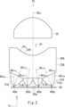
- FIG. 2 is a horizontal cross-sectional view of the vehicle lamp 10 taken along a horizontal plane passing through a low beam light guide lens 30A.
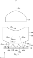
- FIG. 3 is a horizontal cross-sectional view of the vehicle lamp 10 taken along a horizontal plane passing through a high beam light guide lens 30B.
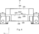
- FIG. The low beam light guiding lens 30A and the high beam light guiding lens 30B are seen from the direction of the arrow A1 in FIG. 2 is a perspective view of a low beam light guide lens 30A (low beam light exit surface 32A) and a high beam light guide lens 30B (high beam light exit surface 32B) as viewed from an oblique direction.
- FIG. 1 is a schematic diagram of a vehicle lamp 10.
- FIG. 2 is a horizontal cross-sectional view of the vehicle lamp 10 taken along a horizontal plane passing through a low beam light guide lens 30A.
- FIG. 3 is a horizontal cross-sectional view of the vehicle lamp 10 taken along
- 2 is an example of a low beam light distribution pattern P Lo formed by a vehicle lamp 10.
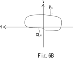
- 2 is an example of a high beam light distribution pattern P Hi formed by the vehicle lamp 10.
- 1 is an example of a composite light distribution pattern P Lo +P Hi obtained by combining a low beam light distribution pattern P Lo and a high beam light distribution pattern P Hi formed by the vehicle lamp 10.
- 1 is a diagram showing an example of a composite light distribution pattern P Lo +P Hi obtained by combining a low beam light distribution pattern P Lo and a high beam light distribution pattern P Hi formed by a vehicle lamp of a comparative example.
- FIG. 1 is a schematic diagram of a vehicle lamp 10.
- the vehicle lamp 10 of this embodiment is a vehicle headlamp that functions as a low beam or high beam headlamp, and is mounted on both the left and right sides of the front end of a vehicle (not shown) such as an automobile. Since the vehicle lamps 10 mounted on both the left and right sides have a symmetrical configuration, the following description will be representative of the vehicle lamp 10 mounted on the right side of the front end of the vehicle (the right side when facing the front of the vehicle).
- the vehicle lamp 10 includes a projection lens 20, a low beam light guide lens 30A which is an example of the first light intensity distribution forming means of the present disclosure, a high beam light guide lens 30B which is an example of the second light intensity distribution forming means of the present disclosure, a low beam light source 40A which is disposed behind the low beam light guide lens 30A and emits a first light Ray1, and a high beam light source 40B which is disposed behind the high beam light guide lens 30B and emits a second light Ray2.
- the XYZ axes are defined below. The X axis extends in the vehicle longitudinal direction, the Y axis extends in the vehicle width direction, and the Z axis extends vertically.
- the projection lens 20 is an aspheric lens.
- the focal point F20 of the projection lens 20 is disposed near the lower edge of the low beam light exit surface 32A (first luminous intensity distribution p1) of the low beam light guide lens 30A.
- the optical axis AX20 of the projection lens 20 extends in the X-axis direction.
- the low beam light source 40A and the high beam light source 40B are semiconductor light emitting elements such as LEDs.
- FIG. 2 is a horizontal cross-sectional view of the vehicle lamp 10 taken along a horizontal plane passing through the low beam light guide lens 30A.
- low beam light sources 40A1 to 40A4 are mounted on the upper stage of the substrate 50 (light source mounting surface 50a) in a row spaced apart from each other in the Y-axis direction.
- the number of low beam light sources 40 is not limited to four, and may be one or more.
- low beam light source 40A when there is no particular need to distinguish between the low beam light sources 40A1 to 40A4 , they will be referred to as low beam light source 40A.
- Figure 3 is a horizontal cross-sectional view of the vehicle lamp 10 taken along a horizontal plane passing through the high beam light guide lens 30B.
- high beam light sources 40B1 to 40B3 are mounted on the lower stage of the substrate 50 (light source mounting surface 50a) in a row spaced apart from each other in the Y-axis direction.
- the number of high beam light sources 40B is not limited to three, and may be one or more.
- high beam light source 40B when there is no particular need to distinguish between the high beam light sources 40B1 to 40B3 , they will be referred to as high beam light source 40B.
- the low beam light source 40A and the high beam light source 40B each have a light emitting surface.
- the light emitting surface is, for example, a rectangular light emitting surface of 1 mm square.
- the low beam light source 40 and the high beam light source 40B are mounted on the substrate 50 (light source mounting surface 50a) with the light emitting surface parallel to the light source mounting surface 50a.
- the optical axes AX 40A1 to AX 40A4 (see FIG. 2) of the low beam light sources 40A 1 to 40A 4 pass through the center of the light emitting surface and extend in a direction perpendicular to the light emitting surface.
- the optical axes AX 40B1 to AX 40B3 see FIG. 3) of the high beam light sources 40B 1 to 40B 3 pass through the center of the light emitting surface and extend in a direction perpendicular to the light emitting surface.
- the low beam light guide lens 30A is disposed above the focal point F20 (and the optical axis AX20 ) of the projection lens 20.
- the low beam light guide lens 30A includes a low beam light entrance portion 31A disposed on the rear side of the vehicle, a low beam light exit surface 32A disposed on the front side of the vehicle, and a low beam light guide portion 33A disposed between the low beam light entrance portion 31A and the low beam light exit surface 32A.
- the low beam light entrance sections 31A1 to 31A4 are arranged in a row in the Y-axis direction with the low beam light sources 40A1 to 40A4 facing each other.
- the low beam light entrance section 31A when there is no particular need to distinguish between the low beam light entrance sections 31A1 to 31A4 , they will be referred to as the low beam light entrance section 31A.
- the first light emitted by the low beam light source 40A1 enters the low beam light guide lens 30A from the low beam light entrance section 31A1 that the low beam light source 40A1 faces. The same applies to the light emitted by the low beam light sources 40A2 to 40A4 .
- the low beam light entrance portion 31A is a cap-type light entrance portion including a central light entrance surface 31A1, a cylindrical peripheral light entrance surface 31A2 extending from the outer periphery of the central light entrance surface 31A1 toward the low beam light source 40A, and a cylindrical peripheral reflective surface 31A3 disposed on the outside of the peripheral light entrance surface 31A2.
- the low beam light entrance portion 31A may be a convex light entrance portion that is convex toward the low beam light source 40A.
- the surface shape of the central light-entering surface 31A1 is configured (adjusted) so that at least a portion of the light Ray1a (see FIG. 1) of the first light Ray1 (light emitted by the low beam light source 40A) entering from the central light-entering surface 31A1 is refracted and focused (at least in the Z-axis direction) toward the lower surface 33A1 of the low beam light guide 33A.
- the surface shapes of the peripheral light-entering surface 31A2 and the peripheral reflecting surface 31A3 are configured (adjusted) so that at least a portion of the light Ray1a (see FIG.
- the low beam entrance sections 31A1 to 31A4 are arranged with their respective optical axes AX31A1 to AX31A4 inclined with respect to the horizontal direction so that the first light Ray1 entering from each of the low beam entrance sections 31A1 to 31A4 is focused near the optical axis AX20 of the projection lens 20 in the horizontal direction.
- the low beam light output surface 32A is curved in a plan view along the rear focal plane FP20 (field curvature) of the projection lens 20. Note that the low beam light output surface 32A only needs to be curved along the rear focal plane FP20 (field curvature) of the projection lens 20, and does not have to completely coincide with the rear focal plane FP20 (field curvature) of the projection lens 20.
- FIG. 4 shows the low beam light guide lens 30A and the high beam light guide lens 30B as viewed from the direction of the arrow A1 in FIG. 2.
- a lower edge 32A1 of the low beam light output surface 32A includes a cutoff shape 32A2 (Z-shaped step portion) corresponding to a cutoff line CL Lo (see FIG. 6A) which is the upper edge of the low beam light distribution pattern P Lo .
- the high beam light guide lens 30B is disposed below the focal point F20 (and the optical axis AX20 ) of the projection lens 20.
- the high beam light guide lens 30B includes a high beam light inlet 31B disposed on the rear side of the vehicle, a high beam light exit surface 32B disposed on the front side of the vehicle, and a high beam light guide 33B disposed between the high beam light inlet 31B and the high beam light exit surface 32B.
- the high beam light entrance sections 31B1 to 31B3 are arranged in a row in the Y-axis direction with the high beam light sources 40B1 to 40B3 facing each other.
- the high beam light entrance section 31B when there is no particular need to distinguish between the high beam light entrance sections 31B1 to 31B3 , they will be referred to as the high beam light entrance section 31B.
- the second light emitted by the high beam light source 40B1 enters the high beam light guide lens 30B from the high beam light entrance section 31B1 that the high beam light source 40B1 faces. The same applies to the light emitted by the high beam light sources 40B2 to 40B3 .
- the high beam light entrance portion 31B is a cap-type light entrance portion including a central light entrance surface 31B1, a cylindrical peripheral light entrance surface 31B2 extending from the outer periphery of the central light entrance surface 31B1 toward the high beam light source 40B, and a cylindrical peripheral reflective surface 31B3 disposed on the outside of the peripheral light entrance surface 31B2.
- the high beam light entrance portion 31B may be a convex light entrance portion that is convex toward the high beam light source 40B.
- the surface shape of the central light-entering surface 31B1 is configured (adjusted) so that at least a portion of the light Ray2a (see FIG. 1) of the second light Ray2 (light emitted by the high beam light source 40B) entering from the central light-entering surface 31B1 is refracted and focused (at least in the Z-axis direction) toward the upper surface 33B1 of the high beam light guide 33B.
- the surface shapes of the peripheral light-entering surface 31B2 and the peripheral reflecting surface 31B3 are configured (adjusted) so that at least a portion of the light Ray2a (see FIG.
- the high beam entrance sections 31B1 to 31B3 are arranged with their respective optical axes AX31B1 to AX31B3 inclined with respect to the horizontal direction so that the second light Ray2 entering from each of the high beam entrance sections 31B1 to 31B3 is focused near the optical axis AX20 of the projection lens 20 in the horizontal direction, as shown in FIG.
- the high beam light output surface 32B is curved along the rear focal plane FP20 (field curvature) of the projection lens 20 in a plan view.
- the high beam light output surface 32B is disposed on the projection lens 20 side by a distance L1 from the low beam light output surface 32A (and the rear focal plane FP20 (field curvature) of the projection lens 20). This allows the lower end of the high beam light distribution pattern to overlap with the upper end of the low beam light distribution pattern. This will be described further below.
- Fig. 5 is a perspective view of the low beam light guide lens 30A (low beam light output surface 32A) and the high beam light guide lens 30B (high beam light output surface 32B) as viewed from an oblique direction.
- an upper edge 32B1 of the high beam output surface 32B includes a cutoff shape 32B2 (Z-shaped step portion) corresponding to a cutoff line CL Hi (see FIG. 6B) which is the lower edge of the high beam distribution pattern P Hi .
- Fig. 6A is an example of a low beam light distribution pattern P Lo formed by the vehicle lamp 10.
- Each light distribution pattern shown in Fig. 6A to Fig. 6C is formed on a virtual vertical screen (located approximately 25 m forward from the front of the vehicle) facing the front of the vehicle.
- the low beam light distribution pattern P Lo shown in FIG. 6A is formed as follows.
- the low beam light sources 40A 1 to 40A 4 are turned on.
- the first light Ray1 (see FIG. 1) emitted by the low beam light source 40A 1 enters the low beam light guide lens 30A from the low beam light entrance section 31A 1 facing the low beam light source 40A 1.
- a part of the first light Ray1 entering from the low beam light entrance section 31A 1 , Ray1a is totally reflected by the lower surface 33A1 of the low beam light guide section 33A and turns back, and exits from the area near the lower edge 32A1 of the low beam light exit surface 32A and near the optical axis AX 20 of the projection lens 20, while the other part of the light Ray1b exits directly from the low beam light exit surface 32A (see FIG. 1).
- a first luminous intensity distribution p1 (see FIG. 1) is formed on the low beam light output surface 32A (near the rear focal plane FP20 (field curvature)).
- the first luminous intensity distribution p1 has a relatively high luminous intensity near its lower edge and near the optical axis AX20 of the projection lens 20.
- the first luminous intensity distribution p1 corresponds to the low beam light distribution pattern P Lo (see FIG. 6A).
- the lower surface 33A1 of the low beam light guide 33A is a total reflection surface extending rearward from the lower edge of the low beam light output surface 32A.
- This first luminous intensity distribution p1 is inverted and projected forward by the projection lens 20 to form a low beam light distribution pattern P Lo as shown in Fig. 6A.
- This low beam light distribution pattern P Lo has excellent long distance visibility with relatively bright areas in the vicinity of the cutoff line CL Lo and in the vicinity of the intersection of the H line and the V line.
- FIG. 6B is an example of a high beam light distribution pattern P Hi formed by the vehicle lamp 10.
- the high beam light distribution pattern P Hi shown in FIG. 6B is formed as follows.
- the high beam light sources 40B 1 to 40B 3 are turned on.
- the second light Ray2 (see FIG. 1) emitted by the high beam light source 40B 1 enters the high beam light guide lens 30B from the high beam light entrance section 31B 1 facing the high beam light source 40B 1.
- a second luminous intensity distribution p2 (see FIG. 1) is formed on the high beam light output surface 32B (near the rear focal plane FP20 (field curvature)).
- the second luminous intensity distribution p2 has a relatively high luminous intensity near its upper edge and near the optical axis AX20 of the projection lens 20.
- the second luminous intensity distribution p2 corresponds to the high beam light distribution pattern PHi (see FIG. 6B).
- the upper surface 33B1 of the high beam light guide 33B is a total reflection surface extending rearward from the upper edge of the high beam light output surface 32B.
- This second luminous intensity distribution p2 is inverted and projected forward by the projection lens 20 to form a high beam light distribution pattern P Hi as shown in Fig. 6B.
- This high beam light distribution pattern P Hi has excellent long distance visibility with relatively bright areas in the vicinity of the cutoff line CL Hi and in the vicinity of the intersection of the H line and the V line.
- FIG. 6C shows an example of a composite light distribution pattern P Lo +P Hi obtained by combining a low beam light distribution pattern P Lo and a high beam light distribution pattern P Hi formed by the vehicle lamp 10.
- the composite light distribution pattern P Lo +P Hi shown in FIG. 6C is formed by simultaneously turning on the low beam light sources 40A 1 to 40A 4 and the high beam light sources 40B 1 to 40B 3 , and then inverting and projecting a first luminous intensity distribution p1 and a second luminous intensity distribution p2 forward by the projection lens 20.
- the black circle indicated by the symbol f20 represents a position corresponding to the focal point F20 of the projection lens 20 (see FIG. 1)
- the black circle indicated by the symbol a represents a position corresponding to the black circle indicated by the symbol A in FIG.
- the composite light distribution pattern P Lo +P Hi includes an overlap region OL where the lower end of the light distribution pattern for high beam P Hi overlaps with the upper end of the light distribution pattern for low beam P Lo .
- the reason why the two light distribution patterns overlap as described above is that the high beam light output surface 32B is disposed a distance L1 closer to the projection lens 20 than the low beam light output surface 32A (and the rear focal plane FP20 (field curvature) of the projection lens 20), as shown in Figures 1 and 5.
- this is because the second luminous intensity distribution p2 is formed a distance L1 closer to the projection lens 20 than the first luminous intensity distribution p1.
- the second light Ray2 OL (see FIG. 1) emitted from the vicinity of the upper edge 32B1 of the high beam light output surface 32B looks like the first light Ray1 emitted from the region L2 between the black circle A (see FIG. 1) of the low beam light output surface 32A and the focal point F 20 of the projection lens 20. Therefore, an overlap region OL is formed in which the lower end of the high beam light distribution pattern P Hi and the upper end of the low beam light distribution pattern P Lo overlap.
- the overlap region OL is relatively brighter than the surroundings. Therefore, the above-mentioned composite light distribution pattern P Lo +P Hi has excellent long-distance visibility.
- the width L3 of the overlap area OL (see FIG. 6C) can be freely adjusted by changing the distance L1. It is preferable to set the distance L1 to a length that reduces the dark area between the low beam light distribution pattern P Lo and the high beam light distribution pattern P Hi . It is more preferable to set the distance L1 so that the overlap area OL is formed not only above the horizontal line H but also below the horizontal line H. In this way, the overlap area OL can illuminate the road surface even brighter.
- the comparative vehicle lamp has the same configuration as the vehicle lamp 10 of the above embodiment, except that the distance L1 (see FIG. 1) between the low beam light output surface 32A and the high beam light output surface 32B is 0 (zero).
- FIG. 7 shows an example of a composite light distribution pattern P Lo +P Hi obtained by combining a low beam light distribution pattern P Lo and a high beam light distribution pattern P Hi formed by a vehicle lamp of a comparative example.
- a dark area G (a dark area that is darker than the surroundings) is formed between the low beam light distribution pattern P Lo and the high beam light distribution pattern P Hi formed by the vehicle lamp of the comparative example.
- an overlap area OL that is relatively brighter than the surroundings is disposed between the low beam light distribution pattern P Lo and the high beam light distribution pattern P Hi (see FIG. 6C ), so it can be seen that the above-mentioned dark area G is not formed.
- the condition for reducing the dark area G between the low beam light distribution pattern and the high beam light distribution pattern (distance L1, see FIG. 1) varies depending on, for example, the sizes of the projection lens 10, the low beam light guide lens 30A, the high beam light guide lens 30B, the low beam light source 40A, and the high beam light source 40B, and the number of low beam light sources 40A and high beam light sources 40B. Therefore, it is difficult to express the condition for reducing the dark area G between the low beam light distribution pattern and the high beam light distribution pattern (distance L1, see FIG. 1) in a specific numerical value.
- the light emitted from the high beam light guiding lens 30B does not pass through a part of the low beam light guiding lens 30A, and the dark area between the low beam light distribution pattern P Lo and the high beam light distribution pattern P Hi can be reduced.
- the high beam light output surface 32B is disposed a distance L1 closer to the projection lens 20 than the low beam light output surface 32A (and the rear focal plane FP20 (field curvature) of the projection lens 20).
- the second luminous intensity distribution p2 is formed a distance L1 closer to the projection lens 20 than the first luminous intensity distribution p1.
- the second light Ray2 OL (see FIG. 1) emitted from the vicinity of the upper edge 32B1 of the high beam light output surface 32B looks like the light of the first light Ray1 emitted from the region L2 between the black circle A (see FIG. 1) of the low beam light output surface 32A and the focal point F 20 of the projection lens 20. Therefore, an overlap region OL is formed in which the lower end of the high beam light distribution pattern P Hi and the upper end of the low beam light distribution pattern P Lo overlap.
- the overlap region OL is relatively brighter than the surroundings. Therefore, it is possible to reduce the dark area between the low beam light distribution pattern P Lo and the high beam light distribution pattern P Hi . As a result, the composite light distribution pattern P Lo +P Hi has an improved light distribution feeling and excellent long-distance visibility.
- the second light emitted from the high beam light guide lens 30B does not pass through a part of the low beam light guide lens 30A, so the decrease in maximum luminous intensity is suppressed compared to the vehicle lamp described in Patent Document 1 above.
- the overlap area OL which is relatively brighter than the surroundings, can illuminate the road surface even brighter.
- the present embodiment it is possible to simultaneously reduce the dark areas between the low beam light distribution pattern P Lo and the high beam light distribution pattern P Hi , suppress the decrease in maximum luminous intensity, and illuminate the road surface more brightly by the overlap region OL.
- At least one of the first luminous intensity distribution forming means and the second luminous intensity distribution forming means may be a matrix light source including a group of semiconductor light-emitting elements.
- the luminous intensity distribution (first luminous intensity distribution p1 or second luminous intensity distribution p2) can be formed by individually controlling the on/off state (including dimming state) of the group of semiconductor light-emitting elements.
- At least one of the first luminous intensity distribution forming means and the second luminous intensity distribution forming means may be a screen member (e.g., a phosphor plate) on which a luminous intensity distribution (first luminous intensity distribution p1, second luminous intensity distribution p2) is formed by light (e.g., laser light) scanned by an optical deflector (e.g., an optical deflector using a MEMS mirror).
- a luminous intensity distribution first luminous intensity distribution p1, second luminous intensity distribution p2
- an optical deflector e.g., an optical deflector using a MEMS mirror
- At least one of the first luminous intensity distribution forming means and the second luminous intensity distribution forming means may be a DMD (Digital Mirror Device) including a group of micromirrors.
- the luminous intensity distribution (first luminous intensity distribution p1 or second luminous intensity distribution p2) can be formed by individually controlling the group of micromirrors, etc.
- the projection lens 20 has a curved rear focal plane FP20 (field curvature), but the present invention is not limited to this.
- a projection lens one or more lenses having a flat rear focal plane FP20 may be used.
Landscapes
- Engineering & Computer Science (AREA)
- General Engineering & Computer Science (AREA)
- Physics & Mathematics (AREA)
- Microelectronics & Electronic Packaging (AREA)
- Optics & Photonics (AREA)
- Non-Portable Lighting Devices Or Systems Thereof (AREA)
Abstract
Description
Claims (10)
- 投影レンズと、
前記投影レンズの焦点より上方にロービーム用配光パターンに対応する第1光度分布を形成する第1光度分布形成手段と、
前記投影レンズの焦点より下方にハイビーム用配光パターンに対応する第2光度分布を形成する第2光度分布形成手段と、を備え、
前記投影レンズの焦点は、前記第1光度分布の下端縁近傍に配置されており、
前記投影レンズは、前記第1光度分布及び前記第2光度分布を投影することにより前記ロービーム用配光パターン及び前記ハイビーム用配光パターンを形成し、
前記ハイビーム用配光パターンの下端部が前記ロービーム用配光パターンの上端部にオーバーラップするように、前記第2光度分布は、前記第1光度分布より前記投影レンズ側に形成される車両用灯具。 - 前記第1光度分布は、その下端縁近傍の光度が相対的に高く、
前記第2光度分布は、その上端縁近傍の光度が相対的に高い請求項1に記載の車両用灯具。 - 前記第1光度分布の下端縁は、前記ロービーム用配光パターンの上端縁であるカットオフラインに対応するカットオフ形状を含み、
前記第2光度分布の上端縁は、前記ハイビーム用配光パターンの下端縁であるカットオフラインに対応するカットオフ形状を含む請求項2に記載の車両用灯具。 - 前記第1光度分布形成手段は、前記投影レンズの焦点より上方に配置されたロービーム用出光面と、前記ロービーム用出光面から出光する第1の光を当該ロービーム用出光面まで導光するロービーム用導光部と、を含むロービーム用導光レンズであり、
前記第1光度分布は、前記第1の光が前記ロービーム用出光面から出光することにより当該ロービーム用出光面に形成され、
前記第2光度分布形成手段は、前記投影レンズの焦点より下方に配置されたハイビーム用出光面と、前記ハイビーム用出光面から出光する第2の光を当該ハイビーム用出光面まで導光するハイビーム用導光部と、を含むハイビーム用導光レンズであり、
前記第2光度分布は、前記第2の光が前記ハイビーム用出光面から出光することにより当該ハイビーム用出光面に形成され、
前記ハイビーム用出光面は、前記ロービーム用出光面より前記投影レンズ側に配置されている請求項1に記載の車両用灯具。 - 前記ロービーム用導光部は、前記ロービーム用出光面の下端縁から後方に向かって延びる全反射面である下面を含み、
前記ハイビーム用導光部は、前記ハイビーム用出光面の上端縁から後方に向かって延びる全反射面である上面を含む請求項4に記載の車両用灯具。 - 前記ロービーム用導光レンズの後方に配置され、前記第1の光を発光するロービーム用光源と、
前記ハイビーム用導光レンズの後方に配置され、前記第2の光を発光するハイビーム用光源と、をさらに備え、
前記ロービーム用導光レンズは、前記ロービーム用光源が対向しかつ当該ロービーム用光源が発光した前記第1の光が入光するロービーム用入光部をさらに含み、
前記ハイビーム用導光レンズは、前記ハイビーム用光源が対向しかつ当該ハイビーム用光源が発光した前記第2の光が入光するハイビーム用入光部をさらに含み、
前記ロービーム用入光部は、当該ロービーム用入光部から前記ロービーム用導光レンズ内に入光した前記第1の光が前記ロービーム用導光部の前記下面に向かって集光するように構成されており、
前記ハイビーム用入光部は、当該ハイビーム用入光部から前記ハイビーム用導光レンズ内に入光した前記第2の光が前記ハイビーム用導光部の前記上面に向かって集光するように構成されている請求項5に記載の車両用灯具。 - 前記ロービーム用出光面の下端縁は、前記ロービーム用配光パターンの上端縁であるカットオフラインに対応する形状であり、
前記ハイビーム用出光面の上端縁は、前記ハイビーム用配光パターンの下端縁であるカットオフラインに対応する形状である請求項4から6のいずれか1項に記載の車両用灯具。 - 前記第1光度分布形成手段及び前記第2光度分布形成手段のうち少なくとも一方は、半導体発光素子群を含むマトリックス光源である請求項1に記載の車両用灯具。
- 前記第1光度分布形成手段及び前記第2光度分布形成手段のうち少なくとも一方は、光偏向器により走査される光により光度分布が形成されるスクリーン部材である請求項1に記載の車両用灯具。
- 前記第1光度分布形成手段及び前記第2光度分布形成手段のうち少なくとも一方は、マイクロミラー群を含むDMD(Digital Mirror Device)である請求項1に記載の車両用灯具。
Priority Applications (3)
| Application Number | Priority Date | Filing Date | Title |
|---|---|---|---|
| US19/149,324 US20260227043A1 (en) | 2023-01-18 | 2024-01-17 | Vehicle lamp fitting |
| CN202480007085.8A CN120476277A (zh) | 2023-01-18 | 2024-01-17 | 车用灯具 |
| DE112024000562.4T DE112024000562T5 (de) | 2023-01-18 | 2024-01-17 | Fahrzeuglampenanordnung |
Applications Claiming Priority (2)
| Application Number | Priority Date | Filing Date | Title |
|---|---|---|---|
| JP2023006022A JP2024101856A (ja) | 2023-01-18 | 2023-01-18 | 車両用灯具 |
| JP2023-006022 | 2023-01-18 |
Publications (1)
| Publication Number | Publication Date |
|---|---|
| WO2024154751A1 true WO2024154751A1 (ja) | 2024-07-25 |
Family
ID=91956133
Family Applications (1)
| Application Number | Title | Priority Date | Filing Date |
|---|---|---|---|
| PCT/JP2024/001102 Ceased WO2024154751A1 (ja) | 2023-01-18 | 2024-01-17 | 車両用灯具 |
Country Status (5)
| Country | Link |
|---|---|
| US (1) | US20260227043A1 (ja) |
| JP (1) | JP2024101856A (ja) |
| CN (1) | CN120476277A (ja) |
| DE (1) | DE112024000562T5 (ja) |
| WO (1) | WO2024154751A1 (ja) |
Families Citing this family (1)
| Publication number | Priority date | Publication date | Assignee | Title |
|---|---|---|---|---|
| JP2026114462A (ja) * | 2024-12-26 | 2026-07-08 | 市光工業株式会社 | 車両用灯具 |
Citations (2)
| Publication number | Priority date | Publication date | Assignee | Title |
|---|---|---|---|---|
| JP2017212170A (ja) * | 2016-05-27 | 2017-11-30 | 株式会社小糸製作所 | 車両用灯具 |
| JP2022094635A (ja) * | 2020-12-15 | 2022-06-27 | 株式会社小糸製作所 | 灯具ユニット |
Family Cites Families (11)
| Publication number | Priority date | Publication date | Assignee | Title |
|---|---|---|---|---|
| JP5248833B2 (ja) * | 2007-10-12 | 2013-07-31 | 株式会社小糸製作所 | 車両用照明灯具 |
| JP2013222553A (ja) * | 2012-04-13 | 2013-10-28 | Koito Mfg Co Ltd | 車両用灯具 |
| EP3179158A4 (en) * | 2014-08-07 | 2018-03-21 | Koito Manufacturing Co., Ltd. | Lamp for vehicles |
| FR3093789B1 (fr) * | 2019-03-14 | 2022-05-27 | Valeo Vision | Dispositif lumineux imageant les surfaces eclairees d’au moins deux collecteurs |
| DE102019118968A1 (de) * | 2019-07-12 | 2021-01-14 | HELLA GmbH & Co. KGaA | Projektionsscheinwerfer für Fahrzeuge |
| CN113137585A (zh) * | 2020-01-20 | 2021-07-20 | 华域视觉科技(上海)有限公司 | 前照灯光学元件、车灯模组、车灯及车辆 |
| CN112628684A (zh) * | 2020-09-29 | 2021-04-09 | 华域视觉科技(上海)有限公司 | 车灯光学元件、车灯模组及车灯 |
| JP7530794B2 (ja) * | 2020-10-02 | 2024-08-08 | 株式会社小糸製作所 | 灯具ユニット |
| EP4368879A4 (en) * | 2021-07-07 | 2025-02-19 | Koito Manufacturing Co., Ltd. | VEHICLE LAMP |
| EP4411219B1 (en) * | 2021-10-01 | 2025-09-03 | Koito Manufacturing Co., Ltd. | Vehicle headlight |
| DE102023125282A1 (de) * | 2023-09-19 | 2025-03-20 | HELLA GmbH & Co. KGaA | Beleuchtungsmodul für ein Fahrzeug |
-
2023
- 2023-01-18 JP JP2023006022A patent/JP2024101856A/ja active Pending
-
2024
- 2024-01-17 WO PCT/JP2024/001102 patent/WO2024154751A1/ja not_active Ceased
- 2024-01-17 CN CN202480007085.8A patent/CN120476277A/zh active Pending
- 2024-01-17 DE DE112024000562.4T patent/DE112024000562T5/de active Pending
- 2024-01-17 US US19/149,324 patent/US20260227043A1/en active Pending
Patent Citations (2)
| Publication number | Priority date | Publication date | Assignee | Title |
|---|---|---|---|---|
| JP2017212170A (ja) * | 2016-05-27 | 2017-11-30 | 株式会社小糸製作所 | 車両用灯具 |
| JP2022094635A (ja) * | 2020-12-15 | 2022-06-27 | 株式会社小糸製作所 | 灯具ユニット |
Also Published As
| Publication number | Publication date |
|---|---|
| DE112024000562T5 (de) | 2025-11-06 |
| US20260227043A1 (en) | 2026-08-06 |
| JP2024101856A (ja) | 2024-07-30 |
| CN120476277A (zh) | 2025-08-12 |
Similar Documents
| Publication | Publication Date | Title |
|---|---|---|
| JP5475395B2 (ja) | 車両用灯具 | |
| WO2018043663A1 (ja) | 車両用灯具 | |
| US10753564B2 (en) | Vehicle headlamp | |
| US20210231279A1 (en) | Vehicular lamp | |
| KR102843780B1 (ko) | 차량용 램프 | |
| US10851960B2 (en) | Vehicular lighting fixture | |
| JP2017212037A (ja) | 車両用前照灯 | |
| JP6659456B2 (ja) | 車両用灯具 | |
| WO2017122629A1 (ja) | 前照灯モジュール及び前照灯装置 | |
| CN112166366B (zh) | 光照射装置 | |
| US11867371B2 (en) | Vehicular light guiding body and vehicular lamp unit | |
| JP6995257B2 (ja) | 車両用前照灯 | |
| WO2022092255A1 (ja) | 車両用前照灯 | |
| KR20220089942A (ko) | 차량용 램프 | |
| JP6725282B2 (ja) | 車両用灯具 | |
| CN114623414A (zh) | 用于车辆的灯 | |
| JP7577673B2 (ja) | 車両用灯具 | |
| JP2024101856A (ja) | 車両用灯具 | |
| KR20220006316A (ko) | 차량용 램프 | |
| WO2023189597A1 (ja) | 車両用灯具 | |
| CN113513734B (zh) | 用于车辆的灯以及包括其的车辆 | |
| US20190154225A1 (en) | Vehicle headlight | |
| US11137125B2 (en) | Vehicle lamp | |
| JP2021120922A (ja) | 照明装置及び車両用灯具 | |
| JP7424169B2 (ja) | 車両用導光体及び車両用灯具ユニット |
Legal Events
| Date | Code | Title | Description |
|---|---|---|---|
| 121 | Ep: the epo has been informed by wipo that ep was designated in this application |
Ref document number: 24744672 Country of ref document: EP Kind code of ref document: A1 |
|
| WWE | Wipo information: entry into national phase |
Ref document number: 202480007085.8 Country of ref document: CN |
|
| WWP | Wipo information: published in national office |
Ref document number: 202480007085.8 Country of ref document: CN |
|
| WWE | Wipo information: entry into national phase |
Ref document number: 112024000562 Country of ref document: DE |
|
| WWP | Wipo information: published in national office |
Ref document number: 112024000562 Country of ref document: DE |
|
| 122 | Ep: pct application non-entry in european phase |
Ref document number: 24744672 Country of ref document: EP Kind code of ref document: A1 |