WO2024154678A1 - コネクタ及び電子機器 - Google Patents
コネクタ及び電子機器 Download PDFInfo
- Publication number
- WO2024154678A1 WO2024154678A1 PCT/JP2024/000702 JP2024000702W WO2024154678A1 WO 2024154678 A1 WO2024154678 A1 WO 2024154678A1 JP 2024000702 W JP2024000702 W JP 2024000702W WO 2024154678 A1 WO2024154678 A1 WO 2024154678A1
- Authority
- WO
- WIPO (PCT)
- Prior art keywords
- connector
- metal fitting
- contact
- contact piece
- insulator
- Prior art date
- Legal status (The legal status is an assumption and is not a legal conclusion. Google has not performed a legal analysis and makes no representation as to the accuracy of the status listed.)
- Ceased
Links
Images


Classifications
-
- H—ELECTRICITY
- H01—ELECTRIC ELEMENTS
- H01R—ELECTRICALLY-CONDUCTIVE CONNECTIONS; STRUCTURAL ASSOCIATIONS OF A PLURALITY OF MUTUALLY-INSULATED ELECTRICAL CONNECTING ELEMENTS; COUPLING DEVICES; CURRENT COLLECTORS
- H01R12/00—Structural associations of a plurality of mutually-insulated electrical connecting elements, specially adapted for printed circuits, e.g. printed circuit boards [PCB], flat or ribbon cables, or like generally planar structures, e.g. terminal strips, terminal blocks; Coupling devices specially adapted for printed circuits, flat or ribbon cables, or like generally planar structures; Terminals specially adapted for contact with, or insertion into, printed circuits, flat or ribbon cables, or like generally planar structures
- H01R12/70—Coupling devices
- H01R12/71—Coupling devices for rigid printing circuits or like structures
Definitions
- This disclosure relates to connectors and electronic devices.
- Patent Document 1 discloses a terminal made of a strip-shaped metal plate with rolled surfaces on both sides, in which a portion of the terminal is plastically deformed by pressing in a direction parallel to the rolled surface, resulting in a contact protrusion that protrudes in the normal direction to the rolled surface.
- This terminal has a high wiping effect, reduces conductive resistance, and increases reliability.
- a connector includes: A connector to be connected to a connection object, an insulator having a sidewall; a plurality of contacts attached to the sidewall; Equipped with.
- the contact is A held portion held by the side wall; A first elastic contact piece that comes into contact with the connection object; A second elastic contact piece that comes into contact with the connection object; a first connecting portion that connects the first and second resilient contact pieces to the held portion; has.
- the first and second resilient contact pieces branch out in different directions from the first connecting portion.
- An electronic device includes: Equipped with the above connector.
- FIG. 1 is an external perspective view showing a connector module according to an embodiment in a state in which a first connector and a second connector are connected to each other, as viewed from above; 1 is an external perspective view showing a connector module according to an embodiment in a state in which a first connector and a second connector are separated from each other, as viewed from above; 2 is an external perspective view showing the first connector alone of FIG. 1 as viewed from above; 4 is an external perspective view showing the first connector of FIG. 3 in an exploded top view.
- FIG. 4 is a cross-sectional view taken along the line VV in FIG. 3.
- 2 is an external perspective view showing the second connector alone of FIG. 1 as viewed from above; 7 is an external perspective view showing the second connector of FIG. 6 in an exploded top view.
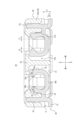
- FIG. 8 is a cross-sectional view taken along the line VIII-VIII in FIG. 2.
- 9 is a cross-sectional view taken along the line IX-IX of FIG.
- the terminals are punched out of a metal plate that has been arranged by rolling, and then bent in the thickness direction of the plate by pressing.
- the connector tends to become large in the longitudinal direction.
- the held portion of the terminal that is to be held in the insulator must protrude in the longitudinal direction of the connector, and the insulators interposed between adjacent terminals, i.e., contacts, make it difficult to miniaturize the connector in the longitudinal direction. For these reasons, it has not been easy to meet the recent demand for miniaturization of connectors.
- the connector and electronic device according to one embodiment of the present disclosure make it possible to achieve both miniaturization and contact reliability.
- FIG. 1 is an external perspective view of a connector module 1 according to one embodiment, in which the first connector 10 and the second connector 50 are connected to each other, as viewed from above.
- FIG. 2 is an external perspective view of a connector module 1 according to one embodiment, in which the first connector 10 and the second connector 50 are separated from each other, as viewed from above.
- the connector module 1 has a first connector 10 and a second connector 50 that can be mated with each other.
- the first connector 10 is connected to a connection object, with the second connector 50 being the connection object.
- the first connector 10 has an insulator 20 and a plurality of contacts 30 attached to the insulator 20.
- the first connector 10 has a first metal fitting 40a and a second metal fitting 40b attached to the insulator 20.
- the second connector 50 mates with the first connector 10.
- the second connector 50 has an insulator 60 that mates with the insulator 20 when the first connector 10 and the second connector 50 are mated with each other.
- the second connector 50 has a contact 70 attached to the insulator 60.
- the contact 70 comes into contact with the contact 30 when the insulator 20 and the insulator 60 are mated with each other.
- the second connector 50 has a metal fitting 80 attached to the insulator 60.
- the metal fitting 80 comes into contact with the first metal fitting 40a and the second metal fitting 40b in the mated state. At this time, the first metal fitting 40a elastically deforms.
- the first connector 10 in one embodiment will be described as a receptacle connector.
- the second connector 50 will be described as a plug connector.
- the first connector 10 in which the contacts 30 elastically deform will be described as a receptacle connector.
- the contacts 70 do not elastically deform will be described as a plug connector.
- the types of the first connector 10 and the second connector 50 are not limited to these.
- the first connector 10 may function as a plug connector
- the second connector 50 may function as a receptacle connector.
- the first connector 10 and the second connector 50 are described as being mounted on the circuit boards CB1 and CB2, respectively.
- the circuit boards CB1 and CB2 may be rigid boards or any other circuit boards.
- at least one of the circuit boards CB1 and CB2 may be a flexible printed circuit board (FPC).
- first connector 10 and the second connector 50 are described as being connected to each other in a direction perpendicular to the circuit boards CB1 and CB2.
- first connector 10 and the second connector 50 are connected to each other along the up-down direction.
- the connection method is not limited to this.
- the first connector 10 and the second connector 50 may be connected to each other in a direction parallel to the circuit boards CB1 and CB2.
- the first connector 10 and the second connector 50 may be connected to each other so that one is perpendicular to the circuit board on which it is mounted, and the other is parallel to the circuit board on which it is mounted.
- the "mating direction” corresponds to the up-down direction, as an example.
- the “removal direction” corresponds to the upward direction, as an example.
- the "insertion direction” corresponds to the downward direction, as an example.
- the “short direction” corresponds to the front-to-back direction, as an example.
- the "first direction” corresponds to the front-to-back direction, as an example.
- the “longitudinal direction” corresponds to the left-to-right direction, as an example.
- the “arrangement direction” corresponds to the left-to-right direction, as an example.
- the "second direction” corresponds to the left-to-right direction, as an example.
- the “mating side” corresponds to the lower side, as an example.
- the “removal side” corresponds to the upper side, as an example.
- the “inner side” corresponds to the direction toward the center of the first connector 10 or the second connector 50.
- the inner side in the front-to-rear direction corresponds to the direction toward the center of the first connector 10 or the second connector 50 in the front-to-rear direction.
- the inner side does not have to be a direction completely toward the center in the front-to-rear direction, but may correspond to a direction toward the center at a slight angle. The same applies to the other directions.
- the "outer side” is the opposite of the inner side.
- FIG. 3 is an external perspective view showing the first connector 10 of FIG. 1 viewed from above.
- the first connector 10 is obtained by integrally molding the second metal fitting 40b and the insulator 20 by insert molding, and then pressing the contacts 30 and the first metal fitting 40a into the insulator 20.
- the contacts 30 are pressed into the insulator 20 from below.
- the first metal fitting 40a is pressed into the insulator 20 from above.
- FIG. 4 is an external perspective view of the first connector 10 of FIG. 3, disassembled and viewed from above.
- the second metal fitting 40b and the insulator 20 are integrally molded by insert molding, but for ease of understanding, FIG. 4 shows the insulator 20 and the second metal fitting 40b as virtually separated components.
- the second metal fitting holding portion 25 of the insulator 20 described below is named as such for convenience, but in reality, the second metal fitting 40b and the insulator 20 are integrally molded by insert molding in these components.
- the second metal fitting holding portion 25 and other components are not inherently part of the insulator 20.
- the insulator 20 constituting the first connector 10 is made of, for example, an insulating and heat-resistant synthetic resin material.
- the insulator 20 extends in a plate shape in the left-right direction.
- the insulator 20 has a bottom plate portion 21 constituting the lower portion.
- the insulator 20 has a mating protrusion 22 that protrudes upward from the center of the bottom plate portion 21 in the front-rear and left-right directions.
- the insulator 20 has an outer peripheral wall 23 that surrounds the mating protrusion 22.
- the outer peripheral wall 23 is located on the outer periphery of the first connector 10.
- the outer peripheral wall 23 surrounds the mating protrusion 22 from four directions, front-rear and left-right.
- the outer peripheral wall 23 has short walls 23a and long walls 23b.
- the short walls 23a extend in the front-rear direction.
- the long walls 23b extend in the left-right direction.
- the insulator 20 has contact mounting grooves 24 arranged inside the longitudinal wall 23b, on the front-rear inner surface of the longitudinal wall 23b, on the bottom plate portion 21, and on the front-rear inner surface of the mating protrusion 22.
- the contacts 30 are attached to the contact mounting grooves 24.
- a number of contact mounting grooves 24 are arranged corresponding to the number of contacts 30.
- the multiple contact mounting grooves 24 are arranged along the arrangement direction of the multiple contacts 30.
- the insulator 20 has a second metal fitting holding portion 25 that extends from the left-right end of the mating protrusion 22 through the bottom plate portion 21 to the short wall 23a.
- the second metal fitting holding portion 25 has a first portion 251 recessed at the left-right end of the mating protrusion 22.
- the second metal fitting holding portion 25 has a second portion 252 that is disposed so as to penetrate the bottom plate portion 21.
- the second metal fitting holding portion 25 has a third portion 253 recessed in the lower surface of the short wall 23a.
- the second metal fitting 40b is attached to the second metal fitting holding portion 25.
- the second metal fitting holding portion 25 extends in the left-right direction so as to connect the mating protrusion 22 and the short wall 23a.
- the insulator 20 has a first metal fitting attachment portion 26 that is disposed across the left and right ends of the long wall 23b and the short wall 23a.
- the first metal fitting 40a is attached to the first metal fitting attachment portion 26.
- the first metal fitting mounting portion 26 is disposed in the center of the short wall 23a in the front-rear direction and has a first wall portion 261 that protrudes outward in the left-right direction.
- the third portion 253 of the second metal fitting holding portion 25 is recessed in the underside of the first wall portion 261.
- the first metal fitting mounting portion 26 has a second wall portion 262 that is disposed on the short wall 23a at a corner of the insulator 20.
- the first metal fitting mounting portion 26 has a third wall portion 263 that is spaced apart from the second wall portion 262 in the left-right direction and is disposed on the long wall 23b.
- the first wall portion 261, the second wall portion 262, and the third wall portion 263 form the outermost rectangular shape of the insulator 20 in the front-rear and left-right directions.
- the first metal fitting mounting portion 26 has a first mounting groove 264 disposed between the first wall portion 261 and the second wall portion 262.
- the first metal fitting mounting portion 26 has a second mounting groove 265 disposed between the second wall portion 262 and the third wall portion 263.
- FIG. 5 is a cross-sectional view taken along the V-V arrow in FIG. 3.
- the insulator 20 has a first groove 27a recessed into the inner side of the longitudinal wall 23b in a first direction perpendicular to the removal direction.
- the first groove 27a is disposed on the inner surface of the longitudinal wall 23b in the front-to-rear direction as part of the contact mounting groove 24.
- the insulator 20 has a second groove 27b recessed into the insulator 20 so as to face the first groove 27a along the first direction.
- the second groove 27b is disposed on the inner surface of the mating protrusion 22 in the front-to-rear direction as part of the contact mounting groove 24.
- the contacts 30 are formed, for example, from a thin plate of spring-elastic copper alloy or Corson copper alloy containing phosphor bronze, beryllium copper, or titanium copper using a progressive die (stamping) into the shape shown in Figures 4 and 5.
- the contacts 30 are made only by punching, without bending in the plate thickness direction.
- the contacts 30 are flat in a second direction parallel to the arrangement direction of the multiple contacts 30.
- the processing method of the contacts 30 may include a step of bending in the plate thickness direction after punching.
- the surface of the contacts 30 is plated with gold, tin, or the like after a base is formed by nickel plating.
- the contact 30 has a mounting portion 31 that extends outward in an L-shape in the front-to-rear direction.
- the contact 30 has a held portion 32 that continues upward from the upper end of the mounting portion 31.
- the held portion 32 has an extending portion that extends linearly from the upper end of the mounting portion 31, and a protrusion that protrudes outward in the front-to-rear direction from the extending portion.
- the contact 30 has a first connecting portion 33 that extends linearly from the held portion 32 toward the inside in the front-to-rear direction.
- the contact 30 has a first elastic contact piece 34 and a second elastic contact piece 35 that branch off in different directions from the first connecting portion 33.
- the first connecting portion 33 connects the first elastic contact piece 34 and the second elastic contact piece 35 to the held portion 32.
- the first elastic contact piece 34 extends linearly from the first connecting portion 33 so as to be inclined inward in the front-to-rear direction along the removal direction.
- the first elastic contact piece 34 has a first contact portion 34a located at the tip of the first elastic contact piece 34. As the first elastic contact piece 34 is inclined inward in the front-to-rear direction along the removal direction, the first contact portion 34a can be largely elastically displaced outward in the front-to-rear direction in response to elastic deformation of the first elastic contact piece 34.
- the second elastic contact piece 35 is arranged in a J-shape.
- the second elastic contact piece 35 extends inward in the front-to-rear direction from the first connecting portion 33 while bending in the direction opposite to the removal direction, and then bends toward the removal direction and extends in the removal direction.
- the second elastic contact piece 35 has an elastic portion 35a configured as a free end, and a second connecting portion 35b that connects the elastic portion 35a to the first connecting portion 33.
- the second connecting portion 35b extends from the first connecting portion 33 along the direction opposite to the removal direction.
- the second connecting portion 35b forms an obtuse angle with the first elastic contact piece 34, and extends from the first connecting portion 33 along the direction opposite to the first elastic contact piece 34.
- the second connecting portion 35b is located closer to the mating side than the first connecting portion 33, and extends from the first connecting portion 33 toward the inside in the front-to-rear direction.
- the elastic portion 35a extends from the second connecting portion 35b in the removal direction.
- the elastic portion 35a bends from the second connecting portion 35b in the removal direction and extends in the removal direction.
- the elastic portion 35a has a second contact portion 35c located at the tip of the second elastic contact piece 35.
- the held portion 32 protrudes in the removal direction further than the first elastic contact piece 34 and the second elastic contact piece 35.
- the removal side tip of the held portion 32 is located on the removal side further than the removal side tip of the first elastic contact piece 34 and the removal side tip of the second elastic contact piece 35.
- the first distance L1 from the mounting portion 31 to the first connecting portion 33 is greater than the second distance L2 from the mounting portion 31 to the second connecting portion 35b.
- the width W2 of the second contact portion 35c is greater than the width W1 of the first contact portion 34a.
- the first metal fitting 40a is formed by using a progressive die (stamping) to form a thin plate of any metal material into the shape shown in FIG. 4.
- the method of processing the first metal fitting 40a includes a process of bending the plate in the thickness direction after punching. However, the method is not limited to this, and the first metal fitting 40a may be processed by a process including drawing.
- the first metal fitting 40a has a first base 41a extending in the front-rear direction.
- the first metal fitting 40a has a second base 42a extending from each of the front-rear end portions of the first base 41a to one side in the left-right direction.
- the first metal fitting 40a has protruding pieces 43a extending linearly downward at the front and rear portions of the first base 41a.
- a recess is formed by the opposing edges of the pair of protruding pieces 43a spaced apart from each other in the front-rear direction and the left-right end edges of the first base 41a.
- the first metal fitting 40a has a first mounting portion 44a located at the lower end of the protruding pieces 43a.
- the first metal fitting 40a has a first locking portion 45a that is wider in the front-rear direction than other portions of the protruding pieces 43a.
- the first metal fitting 40a has a bent portion 46a that bends from the center in the front-to-rear direction to one side in the left-to-right direction at one edge of the first base 41a in the left-to-right direction.
- the first metal fitting 40a has a second locking portion 47a that extends downward from the outer edge in the front-to-rear direction over almost the entire left-to-right direction at the second base 42a.
- the second locking portion 47a has a portion that is wider in the left-to-right direction than the second base 42a.
- the first metal fitting 40a has a second mounting portion 48a that extends over almost the entire left-to-right direction at the lower end of the second locking portion 47a.
- the first metal fitting 40a has an extension 49a that extends inwardly from the edge of the second base 42a opposite the second locking portion 47a.
- the extension 49a extends while bending obliquely downward from a portion located on one side in the left-right direction at the inner edge of the second base 42a in the front-to-rear direction.
- the extension 49a slopes inwardly in the front-to-rear direction from above to below.
- the extension 49a can elastically deform toward the second locking portion 47a along the front-to-rear direction when contact pressure is applied from a free state in which no contact pressure is applied due to contact with the second connector 50.
- the extension 49a has spring elasticity.
- the first metal fitting 40a has a first engagement portion 49a1 that is disposed on the front-rear surface of the extension portion 49a that faces the opposite side to the second engagement portion 47a.
- the first engagement portion 49a1 has a convex portion that protrudes on the opposite side to the second engagement portion 47a on that surface of the extension portion 49a.
- the first metal fitting 40a has a second engagement portion 49a2 that is disposed directly below the first engagement portion 49a1 on that surface of the extension portion 49a.
- the second engagement portion 49a2 has a concave portion that is recessed toward the second engagement portion 47a on that surface of the extension portion 49a.
- the second metal fitting 40b is formed by stamping a thin plate of any metal material into the shape shown in FIG. 4.
- the processing method of the second metal fitting 40b includes processes based on punching and bending in the plate thickness direction. Without being limited to this, the second metal fitting 40b may be processed by a process including drawing so that the front-rear, left-right and upper surfaces of the first base portion 41b described below are continuous without gaps.
- the second metal fitting 40b is made to have a crank-like shape. More specifically, the first base 41b and the second base 42b, which will be described later, are made integrally to have a crank-like shape.
- the second metal fitting 40b has a first base 41b.
- the first base 41b extends linearly from the bottom to the top, and is bent at its upper end toward one side in the left-right direction.
- the first base 41b is arranged in an inverted L shape.
- the second metal fitting 40b has a second base 42b that extends linearly from the lower end of the first base 41b toward the other side in the left-right direction.
- the front-to-rear width of the second base 42b is the same as the front-to-rear width of the first base 41b that is continuous with the second base 42b.
- the second metal fitting 40b has a wide portion 43b that extends in a bifurcated manner to the other side in the left-right direction from the other end of the left-right direction of the second base portion 42b so as to widen in the front-to-rear direction.
- the second metal fitting 40b has a mounting portion 44b that extends in a straight line to the other side in the left-right direction from the center in the front-to-rear direction of the wide portion 43b that is arranged in a bifurcated manner.
- the mounting portion 44b bends diagonally downward from the wide portion 43b and then extends in a straight line to the other side in the left-right direction.
- the mounting portion 44b is located one level lower than the second base portion 42b and the wide portion 43b.
- the contact 30 is pressed into the insulator 20 from below.
- the held portion 32 is positioned in the portion of the contact mounting groove 24 that is located inside the longitudinal wall 23b, and engages with the inner wall surface on the outer side in the front-to-rear direction inside the longitudinal wall 23b.
- the held portion 32 is held by the longitudinal wall 23b, which serves as a side wall. This allows the contact 30 to be held in the contact mounting groove 24.
- the contact 30 is attached to the longitudinal wall 23b.
- the tip of the mounting portion 31 located on the outside in a first direction perpendicular to the removal direction faces the longitudinal wall 23b as a side wall in the removal direction.
- the entire tip of the mounting portion 31 faces the longitudinal wall 23b in the removal direction.
- a space S is disposed between the mounting portion 31 and the longitudinal wall 23b. The mounting portion 31 and the longitudinal wall 23b are spaced apart from each other in the removal direction.
- At least a portion of the first elastic contact piece 34 is accommodated in the first groove portion 27a and faces the insulator 20 in the removal direction. Substantially the entire portion of the first elastic contact piece 34, excluding the inner half of the first contact portion 34a in the front-to-rear direction, is accommodated in the first groove portion 27a. At this time, this portion of the first elastic contact piece 34 is disposed inside the longitudinal wall 23b such that a portion of the longitudinal wall 23b is spaced apart above it.
- the inner half of the first contact portion 34a of the first elastic contact piece 34 in the front-rear direction is exposed from the contact mounting groove 24 between the mating protrusion 22 and the longitudinal wall 23b.
- the first elastic contact piece 34 is elastically deformable in the front-rear direction in the contact mounting groove 24, more specifically, in the first groove portion 27a.
- At least a portion of the second elastic contact piece 35 is accommodated in the second groove portion 27b and faces the insulator 20 in the removal direction. Substantially the entire portion of the second elastic contact piece 35, excluding the outer half of the second contact portion 35c in the front-to-rear direction, is accommodated in the second groove portion 27b. At this time, this portion of the second elastic contact piece 35 is disposed inside the mating protrusion 22 such that a portion of the mating protrusion 22 is spaced apart above it.
- the front-rear tip of the second elastic contact piece 35 protrudes toward the first groove portion 27a from the side surface of the insulator 20 in which the second groove portion 27b is recessed.
- the front-rear tip of the second elastic contact piece 35 corresponds to the second contact portion 35c, as an example.
- the second contact portion 35c protrudes toward the first groove portion 27a from the front-rear inner surface of the mating protrusion 22 in which the second groove portion 27b is recessed, i.e., outward in the front-rear direction.
- the outer front-rear half of the second contact portion 35c is located outward in the front-rear direction from the front-rear inner surface of the mating protrusion 22.
- the outer half of the second contact portion 35c of the second elastic contact piece 35 in the front-rear direction is exposed from the contact mounting groove 24 between the mating protrusion 22 and the longitudinal wall 23b.
- the second elastic contact piece 35 is elastically deformable in the front-rear direction in the contact mounting groove 24, more specifically in the second groove portion 27b.
- the elastic portion 35a is more easily elastically deformed than the second connecting portion 35b.
- the second connecting portion 35b may be elastically deformed like the elastic portion 35a, or may not be elastically deformed like the elastic portion 35a.
- the protruding width T2 of the tip of the second elastic contact piece 35 in the front-rear direction is greater than the protruding width T1 of the tip of the first elastic contact piece 34 in the front-rear direction. More specifically, the protruding width T2 of the outer half of the second contact piece 35c protruding from the second groove portion 27b in the front-rear direction is greater than the protruding width T1 of the inner half of the first contact piece 34a protruding from the first groove portion 27a in the front-rear direction.
- the first metal fitting 40a and the second metal fitting 40b are different members.
- the first metal fitting 40a and the second metal fitting 40b are separate from each other.
- the first metal fitting 40a and the second metal fitting 40b face each other in the left-right direction while separated from each other.
- the strengths of the first metal fitting 40a and the second metal fitting 40b are different from each other.
- the strength of one of the first metal fitting 40a and the second metal fitting 40b is higher than the strength of the other.
- the strength of the second metal fitting 40b may be higher than the strength of the first metal fitting 40a.
- the strength of the material of the second metal fitting 40b may be higher than the strength of the material of the first metal fitting 40a.
- “strength” includes, for example, tensile strength.
- the material of the second metal fitting 40b may be different from the material of the first metal fitting 40a.
- the material of the second metal fitting 40b may be stainless steel, and the material of the first metal fitting 40a may be phosphor bronze.
- the material of the first metal fitting 40a and the material of the second metal fitting 40b may be selected from a group of candidate materials in any combination such that the strength of the second metal fitting 40b is higher than the strength of the first metal fitting 40a.
- the "group of candidate materials” includes, for example, stainless steel, phosphor bronze, iron, Corson copper, titanium copper, beryllium copper, and aluminum.
- the material of the second metal fitting 40b may be the same as the material of the first metal fitting 40a, so long as the strength of the second metal fitting 40b is greater than that of the first metal fitting 40a.
- the strength of the second metal fitting 40b may be greater than that of the first metal fitting 40a, even if the second metal fitting 40b is made of the same material, such as phosphor bronze, because the alloy number, type symbol, and quality are different.
- the strength of the second metal fitting 40b may be greater than that of the first metal fitting 40a, even if the second metal fitting 40b is made of the same material, such as phosphor bronze, because the plate thickness of the second metal fitting 40b is greater than that of the first metal fitting 40a.
- the strength of the contact 30 may be approximately the same as the strength of the first metal fitting 40a.
- the strength of the second metal fitting 40b may be higher than the strength of the contact 30 in addition to the first metal fitting 40a.
- the material of the first metal fitting 40a, the material of the second metal fitting 40b, and the material of the contact 30 may be selected from a group of candidate materials in any combination that satisfies the above-mentioned strength relationship between the first metal fitting 40a, the second metal fitting 40b, and the contact 30.
- the pair of second metal fittings 40b are attached to both ends of the mating protrusion 22 in the longitudinal direction of the first connector 10.
- the second metal fittings 40b extend along the longitudinal direction of the first connector 10 from the mating protrusion 22 to the short wall 23a to which the first metal fittings 40a are attached.
- the second metal fitting 40b is molded integrally with the second metal fitting holding portion 25 of the insulator 20 by insert molding.
- the first base portion 41b is molded integrally with the fitting protrusion 22 from its top surface to its side surface at the left and right ends of the fitting protrusion 22.
- the first base portion 41b is molded integrally with the first portion 251 of the second metal fitting holding portion 25.
- the first base portion 41b covers the entire left and right ends of the fitting protrusion 22 from the outside.
- the second base portion 42b is molded integrally with the bottom plate portion 21.
- the second base portion 42b is molded integrally with a part of the second portion 252 of the second metal fitting holding portion 25.
- the wide portion 43b is molded integrally with the remaining part of the second portion 252 of the second metal fitting holding portion 25.
- the mounting portion 44b is molded integrally with the third portion 253 of the second metal fitting holding portion 25. In this state, the left-right tip of the mounting portion 44b is exposed outward in the left-right direction from the first wall portion 261 of the short wall 23a.
- the second base portion 42b and the wide portion 43b extend along the longitudinal direction of the first connector 10.
- the second base portion 42b and the wide portion 43b extend from the mating protrusion 22 to the short wall 23a to which the first metal fitting 40a is attached.
- the lower surface of the mounting portion 44b is located one step lower than the bottom surface of the bottom plate portion 21 of the insulator 20.
- the mounting portion 44b is located directly below the short wall 23a in the left-right direction.
- the first metal fitting 40a is pressed into the insulator 20 from above.
- the first metal fitting 40a is attached to the outer peripheral wall 23 so that the first wall portion 261 is sandwiched between the recesses formed by the opposing edges of a pair of protruding pieces 43a spaced apart from each other in the front-rear direction and the left-right edge of the first base portion 41a.
- the first locking portion 45a locks onto the first wall portion 261 of the first metal fitting mounting portion 26 on the outer side of the short wall 23a in the left-right direction.
- the pair of protruding pieces 43a spaced apart from each other in the front-rear direction are attached to the first mounting groove 264.
- the second locking portion 47a locks onto the second wall portion 262 and the third wall portion 263 of the first metal fitting mounting portion 26 on the outer side of the long wall 23b in the front-rear direction.
- the second locking portion 47a is attached to the second mounting groove 265. In this way, the first metal fitting 40a is held by the first metal fitting mounting portion 26.
- the first base 41a and the second base 42a of the first fitting 40a are arranged along the outer peripheral wall 23. More specifically, the first base 41a is arranged along the short wall 23a.
- the second base 42a is arranged along the long wall 23b.
- the extension 49a extends from the second base 42a to the inside of the outer peripheral wall 23. The extension 49a is located on the long wall 23b.
- the protrusion included in the first engaging portion 49a1 of the extending portion 49a protrudes on the surface of the extending portion 49a on the side opposite the outer peripheral wall 23.
- the protrusions of the pair of first engaging portions 49a1 face each other in the front-rear direction via the left-right ends of the mating protruding portion 22.
- the pair of first engaging portions 49a1 are arranged in the same left-right and up-down positions on the first fitting 40a.
- the recesses included in the second engaging portion 49a2 of the extension portion 49a are arranged from the surface of the extension portion 49a toward the outer peripheral wall 23.
- the recesses of the pair of second engaging portions 49a2 face each other in the front-rear direction via the left-right ends of the mating protrusion 22.
- the pair of second engaging portions 49a2 are arranged at the same left-right and up-down positions on the first metal fitting 40a.
- the first base portion 41a, the protruding piece 43a, and the bent portion 46a of the first metal fitting 40a are arranged so as to overlap in the left and right direction with the outer left and right ends of the wide portion 43b of the second metal fitting 40b and the mounting portion 44b.
- the first mounting portion 44a is arranged along the outer surface of the short wall 23a in the left-right direction.
- the first mounting portion 44a extends downward from the lower end of the short wall 23a.
- the first mounting portion 44a is arranged on both sides of the mounting portion 44b of the second metal fitting 40b in the short direction of the first connector 10.
- the pair of first mounting portions 44a are positioned so as to sandwich the mounting portion 44b of the second metal fitting 40b from both sides in the front-rear direction.
- the pair of first mounting portions 44a are each arranged at a position symmetrical in the front-rear direction with respect to the mounting portion 44b of the second metal fitting 40b.
- the second mounting portion 48a is arranged along the outer surface of the longitudinal wall 23b in the front-rear direction.
- the second mounting portion 48a extends downward from the lower end of the longitudinal wall 23b.
- the second mounting portion 48a is arranged on both sides of the second metal fitting 40b in the short direction of the first connector 10.
- the pair of second mounting portions 48a are positioned to sandwich the first base portion 41b, the second base portion 42b, and the wide portion 43b of the second metal fitting 40b from both sides in the front-rear direction.
- the pair of second mounting portions 48a are each arranged at a position symmetrical in the front-rear direction with respect to the first base portion 41b, the second base portion 42b, and the wide portion 43b.
- the mounting portion 31 of the contact 30 is soldered to the circuit pattern arranged on the mounting surface of the circuit board CB1.
- the first mounting portion 44a and the second mounting portion 48a of the first metal fitting 40a and the mounting portion 44b of the second metal fitting 40b are soldered to the pattern arranged on the mounting surface.
- each mounting portion is mounted on the circuit board CB1
- the first connector 10 is mounted on the circuit board CB1.
- Electronic components other than the first connector 10 such as a CPU (Central Processing Unit), controller, and memory, are mounted on the mounting surface of the circuit board CB1.
- FIG. 6 is an external perspective view showing the second connector 50 of FIG. 1 as viewed from above.
- the second connector 50 is obtained by integrally molding the contacts 70, the metal fittings 80, and the insulator 60 by insert molding.
- Figure 7 is an external perspective view of the second connector 50 of Figure 6, disassembled and viewed from above.
- the contacts 70, metal fittings 80, and insulator 60 are molded integrally by insert molding, but in Figure 7, the insulator 60, the contacts 70, and metal fittings 80 are virtually separated and shown as individual components for ease of understanding. Accordingly, for example, the contact holding portion 64 of the insulator 60, which will be described later, is named in this manner for convenience.
- the contacts 70, metal fittings 80, and insulator 60 are actually molded integrally by insert molding, and are not part of the original configuration of the insulator 60.
- the insulator 60 is a plate-shaped member extending in the left-right direction, for example, injection molded from an insulating and heat-resistant synthetic resin material.
- the insulator 60 has a bottom plate portion 61 that forms the lower part.
- the insulator 60 has an annular outer peripheral wall 62 that protrudes upward along the outer periphery of the bottom plate portion 61 on the front-rear and left-right sides.
- the outer peripheral wall 62 has a short wall 62a and a long wall 62b.
- the short wall 62a extends in the front-rear direction.
- the long wall 62b extends in the left-right direction.
- the insulator 60 has a fitting recess 63 that is surrounded by the outer peripheral wall 62 from four directions, front-rear, left-right, and right-left.
- the insulator 60 has a contact holding portion 64 that is arranged across the longitudinal wall 62b and the bottom plate portion 61. Contacts 70 are attached to the contact holding portion 64. A number of contact holding portions 64 are arranged corresponding to the number of contacts 70. The multiple contact holding portions 64 are arranged along the arrangement direction of the multiple contacts 70.
- the insulator 60 has a metal fitting holding portion 65 that is arranged from the left and right ends of the long wall 62b to the short wall 62a. Metal fittings 80 are attached to the metal fitting holding portion 65.
- the contact 70 is made by forming a thin plate of, for example, phosphor bronze, beryllium copper, or copper alloy containing titanium copper, or a Corson copper alloy, into the shape shown in FIG. 7 using a progressive die (stamping).
- the surface of the contact 70 is plated with gold or tin after a base is formed with nickel plating.
- the contact 70 has a mounting portion 71 that extends outward in an L-shape in the front-to-rear direction.
- the contact 70 has an extending portion 72 that is connected to the mounting portion 71.
- the extending portion 72 extends upward in a straight line from the upper end of the mounting portion 71 with a left-to-right width greater than that of the mounting portion 71.
- the contact 70 has a folded portion 73 that folds upward from the upper end of the extending portion 72 in an inverted J-shape. In the arrangement direction of the multiple contacts 70, the width of the extending portion 72 is greater than the width of the folded portion 73.
- the left-to-right width of the extending portion 72 is greater than the left-to-right width of the folded portion 73.
- the contact 70 has a first contact portion 74 arranged in the folded portion 73.
- the first contact portion 74 is configured to include a surface facing the outside in the front-to-rear direction of the second connector 50 at the folded portion 73.
- the first contact portion 74 is arranged in a recessed state on the inside in the front-to-rear direction at the free end of the folded portion 73, which faces the mounting portion 71 in the up-down direction.
- the contact 70 has a second contact portion 75 arranged in a position facing the first contact portion 74 at the extending portion 72.
- the second contact portion 75 is configured to include a surface facing the inside in the front-to-rear direction of the second connector 50 at the extending portion 72.
- the metal fitting 80 is made by forming a thin plate of any metal material into the shape shown in FIG. 7 using a progressive die (stamping).
- the processing method for the metal fitting 80 includes a process of bending the plate in the thickness direction after punching.
- the metal fitting 80 has a first base 81 extending in the front-rear direction.
- the metal fitting 80 has a second base 82 extending from each of both front-rear ends of the first base 81 to one side in the left-right direction.
- the metal fitting 80 has a first protruding piece 83 extending downward in an L-shape from almost the entire edge of the other left-right side of the first base 81.
- the metal fitting 80 has a contact portion 831 including a left-right surface of the first protruding piece 83 facing the other left-right side.
- the metal fitting 80 has a first mounting portion 84 located at the lower end of the first protruding piece 83.
- the metal fitting 80 has a bent portion 85 that bends from the center in the front-rear direction to one side in the left-right direction at the edge of one side in the left-right direction of the first base 81.
- the metal fitting 80 has a second protruding piece 86 that extends downward from the outer edge in the front-to-rear direction of the second base 82 over almost the entire left-to-right direction.
- the metal fitting 80 has an engaging portion 861 that is disposed on the surface of the second protruding piece 86 that faces outward in the front-to-rear direction.
- the engaging portion 861 has a recess that is recessed inward in the front-to-rear direction on that surface of the second protruding piece 86.
- the metal fitting 80 has a second mounting portion 87 that is located at the lower end of the second protruding piece 86.
- the contact 70 is molded integrally with the contact holding portion 64 of the insulator 60 by insert molding.
- the contact 70 is attached to the longitudinal wall 62b.
- the first contact portion 74 is arranged along the outer surface of the longitudinal wall 62b in the front-to-rear direction.
- the second contact portion 75 is arranged along the inner surface of the longitudinal wall 62b in the front-to-rear direction.
- the mounting portion 71 extends outward in the front-to-rear direction through the bottom plate portion 61.
- the front-to-rear tip of the mounting portion 71 is located outward in the front-to-rear direction from the longitudinal wall 62b.
- the metal fitting 80 is molded integrally with the metal fitting holding portion 65 of the insulator 60 by insert molding.
- the metal fitting 80 is attached to the outer peripheral wall 62.
- the first protruding piece 83 is attached to the first mounting groove 653.
- the second protruding piece 86 is attached to the second mounting groove 654.
- the first base portion 81 and the bent portion 85 are attached to the upper surface and the inner surface in the left and right directions of the short wall 62a, respectively. As described above, the metal fitting 80 is held by the metal fitting holding portion 65.
- the first base 81 and the second base 82 of the metal fitting 80 are arranged along the outer peripheral wall 62. More specifically, the first base 81 is arranged along the short wall 62a. The second base 82 is arranged along the long wall 62b.
- the recesses included in the engaging portion 861 of the second protruding piece 86 are arranged from the surface of the second protruding piece 86 toward the outer peripheral wall 62.
- the recesses of the pair of engaging portions 861 are arranged along the outer surfaces of the opposing outer peripheral walls 62 in the front-to-rear direction.
- the pair of engaging portions 861 are arranged at the same left-right and up-down positions on the metal fitting 80.
- the metal fitting 80 When the metal fitting 80 is held by the metal fitting holding portion 65 of the insulator 60, it covers substantially the entire short wall 62a and the left and right ends of the long wall 62b.
- the first mounting portion 84 is arranged along the outer surface of the short wall 62a in the left and right direction.
- the first mounting portion 84 is located one step lower than the lower end of the short wall 62a.
- the second mounting portion 87 is arranged along the outer surface of the outer peripheral wall 62 in the front-to-rear direction. The second mounting portion 87 extends downward below the lower end of the outer peripheral wall 62.
- the mounting portion 71 of the contact 70 is soldered to the circuit pattern arranged on the mounting surface of the circuit board CB2.
- the first mounting portion 84 and the second mounting portion 87 of the metal fitting 80 are soldered to the pattern arranged on the mounting surface.
- the second connector 50 is mounted on the circuit board CB2.
- Figure 8 is a cross-sectional view taken along the VIII-VIII arrows in Figure 2.
- Figure 9 is a cross-sectional view taken along the IX-IX arrows in Figure 1.
- the first elastic contact piece 34 of the contact 30 comes into contact with the second connector 50 as the connection object. More specifically, the first contact portion 34a of the first elastic contact piece 34 comes into contact with the second connector 50 as the connection object. The first contact portion 34a comes into contact with the first contact portion 74 of the contact 70.
- the first elastic contact piece 34 which has spring elasticity, comes into contact with the first contact portion 74 of the contact 70, it elastically deforms outward in the front-to-rear direction in the first groove portion 27a.
- first elastic contact piece 34 is elastically deformed by contact with the second connector 50 as the connection object, in the mated state it does not come into contact with the longitudinal wall 23b and is separated from it.
- first elastic contact piece 34 is elastically deformed by contact with the second connector 50 and comes into contact with the longitudinal wall 23b during the mating process when the insulator 20 is mated with the second connector 50 as the connection object.
- the second elastic contact piece 35 of the contact 30 comes into contact with the second connector 50 as the connection object. More specifically, the elastic portion 35a of the second elastic contact piece 35 comes into contact with the second connector 50 as the connection object. The second contact portion 35c of the elastic portion 35a comes into contact with the second connector 50 as the connection object. The second contact portion 35c comes into contact with the second contact portion 75 of the contact 70.
- the second elastic contact piece 35 which has spring elasticity, comes into contact with the second contact portion 75 of the contact 70, it elastically deforms inward in the front-to-rear direction in the second groove portion 27b.
- the second elastic contact piece 35 is elastically deformed due to contact with the second connector 50 as the connection object, it separates without contacting the inner wall of the mating protrusion 22.
- the second elastic contact piece 35 may be elastically deformed due to contact with the second connector 50 and come into contact with the inner wall of the mating protrusion 22 in a mated state in which the insulator 20 is mated with the second connector 50 as the connection object.
- the contact 30 contacts the contact 70 on both the inside and outside of the second connector 50, with the center line of the longitudinal wall 62b in the front-to-rear direction as the boundary.
- the contact 30 and the contact 70 contact at two points, including one point by the first elastic contact piece 34 and the first contact portion 74 located on the outside, and one point by the second elastic contact piece 35 and the second contact portion 75 located on the inside.
- the first metal fitting 40a and the metal fitting 80 come into contact with each other.
- the extension portion 49a of the first metal fitting 40a and the second protruding piece 86 of the metal fitting 80 come into contact with each other.
- the first engagement portion 49a1 of the extension portion 49a and the engagement portion 861 of the second protruding piece 86 engage with each other based on the concave-convex structure.
- the extension 49a which has spring elasticity, elastically deforms outward in the front-to-rear direction upon contact with the second protruding piece 86.
- the extension 49a comes into contact with the metal fitting 80 and elastically deforms toward the outer peripheral wall 23 of the insulator 20.
- the first metal fitting 40a and the metal fitting 80 come into contact at two points on both the front and rear sides via the extension 49a and the second protruding piece 86.
- the first metal fitting 40a and the metal fitting 80 come into contact with each other.
- the bent portion 46a of the first metal fitting 40a and the first protruding piece 83 of the metal fitting 80 come into contact with each other.
- the inner surface in the left-right direction of the bent portion 46a and the surface included in the contact portion 831 of the first protruding piece 83 come into contact with each other.
- the first metal fitting 40a and the metal fitting 80 come into contact at one point in the left-right direction by the bent portion 46a and the first protruding piece 83.
- the upper surfaces of the second base 42b and the wide portion 43b of the second fitting 40b are flush with the upper surface of the bottom plate portion 21.
- the upper surfaces of the second base 42b and the wide portion 43b are exposed upward from the second portion 252 of the bottom plate portion 21.
- the second fitting 40b and the fitting 80 come into contact with each other.
- the upper surfaces of the second base 42b and the wide portion 43b of the second fitting 40b come into contact with the surface of the first base 81 of the fitting 80.
- the second fitting 40b and the fitting 80 come into contact at one point in the vertical direction by the upper surfaces of the second base 42b and the wide portion 43b and the surface of the first base 81.
- the first connector 10 makes it possible to achieve both miniaturization and contact reliability.
- the first elastic contact piece 34 and the second elastic contact piece 35 branch off in different directions from the first connecting portion 33, and are capable of elastic deformation independently of each other.
- the first elastic contact piece 34 and the second elastic contact piece 35 are arranged in a bifurcated shape on either side of the first connecting portion 33, and are capable of elastic deformation independently of each other.
- the first connector 10 has a contact structure with the contact 70 of the second connector 50 at two points based on the first elastic contact piece 34 and the second elastic contact piece 35 that elastically deform independently of each other. Therefore, the first connector 10 can improve the contact reliability between the contact 30 and the contact 70 even when the first connector 10 is miniaturized.
- the first connector 10 has the first connecting portion 33 facing the insulator 20 in the removal direction, which reduces the possibility of the contacts 30 coming out of the first connector 10 in the removal direction when the second connector 50 is removed as the connection object. This allows the first connector 10 to maintain its reliability as a product, including the above-mentioned contact reliability.
- the first connector 10 at least a portion of the first elastic contact piece 34 is accommodated in the first groove portion 27a and faces the insulator 20 in the removal direction. This allows the first connector 10 to reduce the likelihood of the contact 30 coming out of the first connector 10 in the removal direction when the second connector 50 as the connection object is removed. This allows the first connector 10 to maintain its reliability as a product, including the above-mentioned contact reliability.
- the first connector 10 can achieve miniaturization in the first direction by overlapping at least a portion of the first elastic contact piece 34 of the contact 30 with the longitudinal wall 23b of the insulator 20.
- the first connector 10 In the first connector 10, at least a portion of the second elastic contact piece 35 is accommodated in the second groove portion 27b and faces the insulator 20 in the removal direction. This allows the first connector 10 to reduce the likelihood of the contact 30 coming out of the first connector 10 in the removal direction when the second connector 50 as the connection object is removed. This allows the first connector 10 to maintain its reliability as a product, including the above-mentioned contact reliability.
- the first connector 10 can achieve miniaturization in the first direction by overlapping at least a portion of the second elastic contact piece 35 of the contact 30 with the mating protrusion 22 of the insulator 20.
- the first connector 10 is capable of large elastic displacement of the second elastic contact piece 35 by having the tip of the second elastic contact piece 35 protrude toward the first groove portion 27a from the side surface of the mating convex portion 22. More specifically, the second elastic contact piece 35 is capable of large elastic displacement by continuously contacting the contact 70 during mating with the second contact portion 35c exposed from the second groove portion 27b. Therefore, the first connector 10 is capable of improving the contact reliability between the contact 30 and the contact 70 even when the first connector 10 is miniaturized.
- the first connector 10 has a configuration described below in which the spring of the elastic portion 35a in the mating direction is long, and thus synergistically achieves the effects of large elastic displacement and improved contact reliability.
- the first connector 10 is capable of large elastic displacement of the first elastic contact piece 34 by having the tip of the first elastic contact piece 34 protrude toward the second groove portion 27b from the side surface of the longitudinal wall 23b. More specifically, the first elastic contact piece 34 is capable of large elastic displacement by continuously contacting the contact 70 during mating because the first contact portion 34a is exposed from the first groove portion 27a. Therefore, the first connector 10 is capable of improving the contact reliability between the contact 30 and the contact 70 even when the connector 10 is miniaturized.
- the first connector 10 is capable of greater elastic displacement of the second elastic contact piece 35 relative to the first elastic contact piece 34 because the protruding width T2 of the tip of the second elastic contact piece 35 is greater than the protruding width T1 of the tip of the first elastic contact piece 34. More specifically, the second elastic contact piece 35 is in continuous contact with the contact 70 over a larger area during mating because the protruding width T2 is greater than the protruding width T1, allowing for greater elastic displacement. Therefore, the first connector 10 is capable of improving the contact reliability between the contact 30 and the contact 70 even when miniaturized.
- the second connecting portion 35b extends from the first connecting portion 33 in the direction opposite to the removal direction, and the elastic portion 35a extends from the second connecting portion 35b in the removal direction.
- the second contact portion 35c can be greatly elastically displaced in the front-rear direction in accordance with the elastic deformation of the second elastic contact piece 35. Therefore, the first connector 10 can improve the contact reliability between the contacts 30 and the contacts 70 even when it is miniaturized.
- the first connector 10 is capable of greater elastic displacement of the second elastic contact piece 35 in the first direction perpendicular to the removal direction because the width W2 of the second contact portion 35c is greater than the width W1 of the first contact portion 34a. More specifically, the larger width W2 of the second elastic contact piece 35 allows it to continuously contact the contact 70 over a larger area during mating, enabling it to undergo greater elastic displacement. Therefore, the first connector 10 is capable of improving the contact reliability between the contact 30 and the contact 70 even when miniaturized.
- the first connector 10 has the above-mentioned configuration in which the spring of the elastic portion 35a in the mating direction is long, and thus provides the synergistic effects of greater elastic displacement and improved contact reliability.
- the first connector 10 because the first distance L1 is greater than the second distance L2, can reduce solder rise from the mounting portion 31 toward the first elastic contact piece 34 and the second elastic contact piece 35 even when the connector is made low-profile.
- the height from the mounting portion 31 to the first connecting portion 33 is greater than the second connecting portion 35b. Therefore, the first connector 10 can reduce the possibility of solder rising to the first connecting portion 33 and reaching the first elastic contact piece 34 and the second elastic contact piece 35 via the first connecting portion 33.
- At least a part of the tip of the mounting section 31 located on the outside in the first direction perpendicular to the removal direction faces the longitudinal wall 23b in the removal direction. This prevents the tip of the mounting section 31 from protruding significantly outward in the front-to-rear direction relative to the longitudinal wall 23b. Therefore, the first connector 10 can be made smaller in size in the first direction by overlapping the tip of the mounting section 31 of the contact 30 with the longitudinal wall 23b of the insulator 20.
- a space S is provided between the mounting section 31 and the longitudinal wall 23b serving as a side wall. This makes it possible to provide a space S above the mounting section 31 for the solder to enter, while also realizing a reduction in size of the first connector 10 in the first direction by placing the mounting section 31 inside the first connector 10.
- the first connector 10 can reduce a decrease in contact reliability due to deformation and breakage of the first elastic contact piece 34 and the second elastic contact piece 35 by having the retained portion 32 protrude in the removal direction beyond the first elastic contact piece 34 and the second elastic contact piece 35.
- the tip of the retained portion 32 is inserted into the insulator 20 before the tips of the first elastic contact piece 34 and the second elastic contact piece 35. Therefore, when the contact 30 is pressed into the insulator 20, the possibility that the first elastic contact piece 34 and the second elastic contact piece 35 will erroneously contact the insulator 20 is reduced. As a result, the possibility that the contact 30 will be deformed and broken at the first elastic contact piece 34 and the second elastic contact piece 35 is reduced, and the first connector 10 can maintain contact reliability.
- the first connector 10 is able to reduce deterioration of the first elastic contact piece 34 as a spring caused by excessive elastic deformation outward in the front-to-rear direction during mating by the first elastic contact piece 34 elastically deforming during mating and coming into contact with the longitudinal wall 23b. Therefore, even after transitioning from the middle of mating to the mated state, the contact pressure exerted by the contact 30 on the contact 70 can be maintained. Therefore, the first connector 10 is able to maintain the contact reliability between the contact 30 and the contact 70 even when miniaturized.
- the first connector 10 has contacts 30 that are flat in a second direction parallel to the arrangement direction, making it possible to reduce the width of the contacts 30 in the second direction and the spacing between adjacent contacts 30, thereby achieving miniaturization in the second direction.
- the first connector 10 has a convex portion in the first engagement portion 49a1, so that when mated with the second connector 50, the engagement portion 861 of the metal fitting 80 of the second connector 50 engages with the convex portion of the first engagement portion 49a1, improving the clicking sensation.
- the first connector 10 can improve the removal force when removing the second connector 50 from the first connector 10 in the mated state.
- the first metal fitting 40a has an elastically deformable extension 49a that contacts the metal fitting 80 in the mated state, and the elastic force of the extension 49a allows the connection with the metal fitting 80 to be stably maintained. Therefore, electrical continuity between the first metal fitting 40a and the metal fitting 80 is stably maintained in the mated state.
- the second metal fitting 40b attached to the mating protrusion 22 and the first metal fitting 40a attached to the outer peripheral wall 23 are different members. This reduces the impact of contact between the metal fitting and the second connector 50 during mating, compared to the conventional technology in which the metal fittings are made as a single unit. For example, even if the metal fitting and the second connector 50 come into contact with each other on one side of the mating protrusion 22 and the outer peripheral wall 23, the impact of the contact on the other side is reduced. This reduces damage to the metal fittings, including the first metal fitting 40a and the second metal fitting 40b. By reducing damage to the metal fittings, damage to the insulator 20 to which the metal fittings are attached is also reduced. As a result, the reliability of the first connector 10 as a product is improved.
- the first metal fitting 40a and the second metal fitting 40b are made of different materials, which makes it possible to make the strength of one of the first metal fitting 40a and the second metal fitting 40b higher than the strength of the other.
- the first metal fitting 40a and the second metal fitting 40b are attached for different purposes in different locations, such as the mating protrusion 22 and the outer peripheral wall 23, and it is possible to manufacture each metal fitting with an appropriate strength suited to the location and purpose. For example, if the metal fittings are manufactured as a single unit as in the conventional technology, when the strength of the metal fittings must be reduced on one side of the mating protrusion 22 and the outer peripheral wall 23, the strength of the metal fittings will inevitably be reduced on the other side as well.
- the main purpose of the second metal fitting 40b attached to the mating protrusion 22 is to improve the robustness of the mating protrusion 22.
- one of the purposes of the first metal fitting 40a attached to the outer peripheral wall 23 is to make contact with the metal fitting 80 in the mated state to obtain electrical continuity.
- an elastically deformable extension 49a is arranged on the first metal fitting 40a.
- the first metal fitting 40a is made of a material strong enough to provide spring properties, while the second metal fitting 40b is made of a material with even greater strength.
- the first metal fitting 40a and the second metal fitting 40b can be made with appropriate strength suited to their respective purposes. For example, if the metal fittings are made integrally as in the prior art, the strength of the entire metal fitting will inevitably be reduced by arranging the elastically deformable contact piece on the outer peripheral wall side, and the robustness of the mating protrusions will also be reduced.
- the strength of the material of the second metal fitting 40b is greater than the strength of the material of the first metal fitting 40a, improving the robustness of the mating protrusion 22 to which the second metal fitting 40b is attached. This reduces damage to the mating protrusion 22 of the insulator 20 to which the second metal fitting 40b is attached. As a result, the reliability of the first connector 10 as a product is improved.
- the thickness of the second metal fitting 40b is greater than the thickness of the first metal fitting 40a, so that even if the first metal fitting 40a and the second metal fitting 40b are made of the same material, the strength of the second metal fitting 40b is greater than the strength of the first metal fitting 40a. This improves the robustness of the mating protrusion 22 to which the second metal fitting 40b is attached in the same manner as described above.
- the second metal fitting 40b has a mounting portion 44b that is mounted on the circuit board CB1, thereby improving the robustness of the second metal fitting 40b. Even if a load is applied to the second metal fitting 40b, the deformation is reduced, and the shape and dimensional accuracy of the first connector 10 are maintained even during mating. For example, the robustness of the mating protrusion 22 to which the second metal fitting 40b is attached is improved. Therefore, damage such as deformation of the mating protrusion 22 is reduced, and the above-mentioned effect regarding longitudinal positional deviation and rattling of the first connector 10 is obtained.
- the mounting portion 44b includes a bottom surface on the circuit board CB1 side, external forces acting on the second metal fitting 40b can be received by the mounting portion 44b.
- the second metal fitting 40b is fixed to the circuit board CB1, and even if an external force acts on the second metal fitting 40b, the impact is absorbed by the mounting portion 44b. This improves the robustness of the second metal fitting 40b along the longitudinal direction of the first connector 10. This also improves the robustness of the mating protrusion 22 along the longitudinal direction of the first connector 10.
- the first base 41b and the second base 42b are integrally manufactured to have a crank shape, so that the entire second metal fitting 40b is integrated with the insulator 20 along the end of the mating protrusion 22 and the shape of the bottom plate 21. This improves the holding strength of the second metal fitting 40b against the insulator 20.
- the pair of first mounting portions 44a are positioned at approximately the same left-right position as mounting portion 44b, so that the three mounting portions are positioned on a straight line along the front-rear direction. This improves the mounting strength of the first connector 10 to the circuit board CB1. For example, even if the second connector 50 is mated with the first connector 10 misaligned at a predetermined angle around the vertical axis, the mounting of the first connector 10 to the circuit board CB1 is maintained. Similarly, even if the circuit board CB1 on which the first connector 10 is mounted rotates after mating, the mounting of the first connector 10 to the circuit board CB1 is maintained. Therefore, the robustness of the first connector 10 mounted on the circuit board CB1 is improved.
- the robustness of the short walls 23a is improved at both left and right ends of the outer peripheral wall 23. Therefore, damage to the short walls 23a of the insulator 20 to which the pair of first fittings 40a are attached is reduced. As a result, the reliability of the first connector 10 as a product is improved.
- the first contact portion 74 of the second connector 50 is recessed one step on the inside in the front-to-rear direction at the free end of the folded portion 73, so that in the mated state shown in FIG. 9, the stepped portion of the first contact portion 74 and the front-to-rear tip of the first elastic contact piece 34 engage with each other.
- This increases the removal force required when removing one of the first connector 10 and the second connector 50 from the other in the mated state. This makes it more difficult for one to come off from the other, improving the reliability of the connector module 1 as a product.
- the shape, size, arrangement, orientation, and number of each of the components described above are not limited to the above description and the illustrations in the drawings.
- the shape, size, arrangement, orientation, and number of each component may be configured arbitrarily as long as it can realize its function.
- the assembly method of the first connector 10 and the second connector 50 described above is not limited to the above description.
- the assembly method of the first connector 10 and the second connector 50 may be any method as long as the first connector 10 and the second connector 50 can be assembled so that their respective functions are fulfilled.
- at least one of the contacts 30 and the first metal fitting 40a may be integrally molded with the insulator 20 by insert molding rather than press fitting.
- the second metal fitting 40b may be attached to the insulator 20 by press fitting rather than insert molding.
- at least one of the contacts 70 and the metal fitting 80 may be attached to the insulator 60 by press fitting rather than insert molding.
- the first connecting portion 33 is described as facing the insulator 20 in the removal direction, but this is not limited to the above.
- the first connecting portion 33 does not have to face the insulator 20 in the removal direction.
- the insulator 20 is described as having a first groove portion 27a recessed on the inside of the longitudinal wall 23b in the first direction, but this is not limited thereto.
- the insulator 20 does not have to have such a first groove portion 27a.
- the first elastic contact piece 34 is accommodated in the first groove portion 27a and faces the insulator 20 in the removal direction, but this is not limited to the above.
- the entire first elastic contact piece 34 does not have to be accommodated in the first groove portion 27a, and does not have to face the insulator 20 in the removal direction.
- the insulator 20 has been described as having a second groove portion 27b recessed into the insulator 20 so as to face the first groove portion 27a along the first direction, but this is not limited thereto.
- the insulator 20 does not have to have such a second groove portion 27b.
- the second elastic contact piece 35 is accommodated in the second groove portion 27b and faces the insulator 20 in the removal direction, but this is not limited to the above.
- the entire second elastic contact piece 35 does not have to be accommodated in the second groove portion 27b, and does not have to face the insulator 20 in the removal direction.
- the tip of the second elastic contact piece 35 is described as protruding toward the first groove portion 27a from the side surface of the insulator 20 in which the second groove portion 27b is recessed, but this is not limited to the above.
- the tip of the second elastic contact piece 35 does not have to protrude toward the first groove portion 27a from the side surface.
- the tip of the first elastic contact piece 34 is described as protruding toward the second groove portion 27b from the side surface of the longitudinal wall 23b in which the first groove portion 27a is recessed, but this is not limited to the above.
- the tip of the first elastic contact piece 34 does not have to protrude toward the second groove portion 27b from the side surface.
- the protruding width T2 of the tip of the second elastic contact piece 35 is described as being greater than the protruding width T1 of the tip of the first elastic contact piece 34, but this is not limited thereto.
- the protruding width T2 of the tip of the second elastic contact piece 35 may be less than or equal to the protruding width T1 of the tip of the first elastic contact piece 34.
- the second elastic contact piece 35 has been described as having an elastic portion 35a and a second connecting portion 35b, but this is not limited thereto.
- the second elastic contact piece 35 does not have to have the second connecting portion 35b.
- the elastic portion 35a may be directly connected to the first connecting portion 33 without going through the second connecting portion 35b.
- the width W2 of the second contact portion 35c is greater than the width W1 of the first contact portion 34a in the first direction perpendicular to the removal direction, but this is not limited to the above.
- the width W2 may be less than or equal to the width W1.
- the first contact portion 34a is described as being located at the tip of the first elastic contact piece 34, but this is not limited to this.
- the first contact portion 34a may be located at any other position on the first elastic contact piece 34 other than the tip.
- the number of first contact portions 34a located on the first elastic contact piece 34 is also not limited to one, and may be multiple.
- the second contact portion 35c is described as being located at the tip of the second elastic contact piece 35, but this is not limited to this.
- the second contact portion 35c may be located at any other position on the second elastic contact piece 35 other than the tip.
- the number of second contact portions 35c located on the second elastic contact piece 35 is also not limited to one, and may be multiple.
- the first distance L1 from the mounting portion 31 to the first connecting portion 33 is greater than the second distance L2 from the mounting portion 31 to the second connecting portion 35b, but this is not limited thereto.
- the first distance L1 may be equal to or less than the second distance L2.
- the tip of the mounting portion 31 located on the outside in the first direction perpendicular to the removal direction is described as facing the longitudinal wall 23b in the removal direction, but this is not limited to the above.
- the entire tip of the mounting portion 31 does not have to face the longitudinal wall 23b in the removal direction.
- the entire tip of the mounting portion 31 may protrude outward in the front-to-rear direction relative to the longitudinal wall 23b.
- a space S is disposed between the mounting portion 31 and the longitudinal wall 23b in the removal direction, but this is not limited thereto.
- the space S does not have to be disposed in the first connector 10.
- the mounting portion 31 and the longitudinal wall 23b may be in contact with each other in the removal direction.
- the held portion 32 is described as protruding in the removal direction further than the first elastic contact piece 34 and the second elastic contact piece 35, but this is not limited to the above.
- the held portion 32 does not have to protrude in the removal direction further than at least one of the first elastic contact piece 34 and the second elastic contact piece 35.
- the first elastic contact piece 34 is described as being elastically deformed by contact with the second connector 50 during mating and coming into contact with the longitudinal wall 23b, but this is not limited to the above.
- the first elastic contact piece 34 does not have to be in contact with the longitudinal wall 23b during mating, just as it is in the mated state.
- the contacts 30 are described as being flat in the second direction parallel to the arrangement direction of the multiple contacts 30, but this is not limited thereto.
- the contacts 30 do not have to be flat in the second direction.
- the contacts 30 may be shaped to have a locking portion that extends in the second direction like the conventional terminals described in Patent Document 1, based on a process of bending the contacts 30 in the plate thickness direction after punching.
- the second connecting portion 35b is described as making an obtuse angle with respect to the first elastic contact piece 34 and extending from the first connecting portion 33 along the opposite direction to the first elastic contact piece 34, but this is not limited thereto.
- the second connecting portion 35b may also make a right angle or an acute angle with respect to the first elastic contact piece 34.
- the first elastic contact piece 34 is described as being inclined inward in the front-rear direction along the removal direction, but this is not limited to this.
- the first elastic contact piece 34 may be inclined outward in the front-rear direction along the removal direction, or may not be inclined either inward or outward.
- the multiple contacts 30 are arranged in two rows in the front-rear direction, but this is not limited to this.
- the multiple contacts 30 may also be arranged in one row in the front-rear direction.
- the extensions 49a are described as being arranged in pairs on the first metal fitting 40a, but this is not limited to the above.
- the extensions 49a may be arranged in two or more pairs at any position on the first metal fitting 40a, or may not be arranged in pairs but may be arranged in any number of one or more at any position.
- extension portion 49a is described as being located on the long wall 23b, but this is not limited to the above.
- the extension portion 49a may be located on the short wall 23a instead of or in addition to the long wall 23b.
- the first metal fitting 40a and the second metal fitting 40b are described as being separate from each other, but this is not limited thereto.
- the first metal fitting 40a and the second metal fitting 40b may be connected to each other without being separated from each other.
- the first metal fitting 40a and the second metal fitting 40b may be manufactured so that their respective strengths are different from each other within the entire integrated metal fitting.
- the integrated metal fitting including the first metal fitting 40a and the second metal fitting 40b may be manufactured from a functionally graded material. More specifically, the material of the second metal fitting 40b may be a material different from that of the first metal fitting 40a so that its strength is higher than that of the material of the first metal fitting 40a.
- the integrated metal fitting including the first metal fitting 40a and the second metal fitting 40b may be manufactured so that the plate thickness changes. More specifically, the plate thickness of the second metal fitting 40b may be larger than the plate thickness of the first metal fitting 40a.
- the strength of the second metal fitting 40b is greater than the strength of the first metal fitting 40a, but this is not limited to the above.
- the strength of the first metal fitting 40a may be greater than the strength of the second metal fitting 40b.
- the plate thickness of the second metal fitting 40b may be greater than the plate thickness of the first metal fitting 40a so that the strength of the second metal fitting 40b is greater than the strength of the first metal fitting 40a, but this is not limited to the above.
- the plate thickness of the second metal fitting 40b may be smaller than the plate thickness of the first metal fitting 40a, but the strength of the second metal fitting 40b may be greater than the strength of the first metal fitting 40a.
- the plate thickness of the second metal fitting 40b may be greater than the plate thickness of the first metal fitting 40a, but the strength of the second metal fitting 40b may be lower than the strength of the first metal fitting 40a.
- the mounting portion 44b is described as being located directly below the short wall 23a, but this is not limited to this.
- the mounting portion 44b may be located adjacent to the mating protrusion 22 so as to be close to a position on the second metal fitting 40b where an external force is likely to act.
- the first metal fitting 40a is described as being attached to the short wall 23a, but this is not limited to the above.
- the first metal fitting 40a may not be attached to the short wall 23a, but may be attached only to the long wall 23b.
- the first mounting portion 44a of the first metal fitting 40a is described as being arranged on both sides of the second metal fitting 40b in the short direction of the first connector 10, but this is not limited to this.
- the second mounting portion 48a of the first metal fitting 40a is described as being arranged on both sides of the second metal fitting 40b in the short direction of the first connector 10, but this is not limited to this. Only one of the first mounting portion 44a and the second mounting portion 48a may be arranged on both sides of the second metal fitting 40b in the short direction of the first connector 10. Only one first mounting portion 44a may be arranged instead of two, or three or more. Similarly, only one second mounting portion 48a may be arranged instead of two, or three or more.
- the first connector 10 and connector module 1 as described above are mounted on an electronic device including a circuit board CB1 and a circuit board CB2.
- electronic devices include wearable devices such as smart watches, wireless earphones, and smart glasses, terminal devices such as smartphones, and any information processing devices such as personal computers, copiers, printers, facsimiles, and multifunction devices.
- electronic devices include any industrial equipment.
- Such electronic devices enable both miniaturization and contact reliability in the first connector 10 and connector module 1.
- a connector to be connected to a connection object an insulator having a sidewall; a plurality of contacts attached to the sidewall; Equipped with The contact is A held portion held by the side wall; A first elastic contact piece that comes into contact with the connection object; A second elastic contact piece that comes into contact with the connection object; a first connecting portion that connects the first and second resilient contact pieces to the held portion; having the first elastic contact piece and the second elastic contact piece branch out in different directions from the first connecting portion; connector.
- Appendix 2 2.
- the first coupling portion faces the insulator in a removal direction in which the connection object is removed from the connector; connector.
- connector [Appendix 3] 3.
- the connector according to claim 2, the insulator has a first groove portion recessed into an inner side of the side wall in a first direction perpendicular to the removal direction, At least a portion of the first elastic contact piece is received in the first groove portion and faces the insulator in the removal direction.
- connector [Appendix 4] 4.
- the insulator has a second groove portion recessed in the insulator to face the first groove portion along the first direction, At least a portion of the second elastic contact piece is received in the second groove portion and faces the insulator in the removal direction. connector.
- a tip end portion of the second elastic contact piece protrudes toward the first groove portion beyond a side surface of the insulator in which the second groove portion is recessed; connector.
- Connectix 6 6.
- the connector according to claim 5 a tip end portion of the first elastic contact piece protrudes toward the second groove portion beyond a side surface of the side wall in which the first groove portion is recessed; connector.
- Appendix 7 7.
- the connector according to claim 6, A protruding width of the tip end of the second elastic contact piece is larger than a protruding width of the tip end of the first elastic contact piece. connector.
- Appendix 8 8.
- the second elastic contact piece has an elastic portion that contacts the connection object and a second connecting portion that connects the elastic portion to the first connecting portion, The second connecting portion extends from the first connecting portion along a direction opposite to the removal direction, The elastic portion extends from the second connecting portion in the removal direction.
- connector [Appendix 9] 9.
- the first elastic contact piece has a first contact portion that comes into contact with the connection object, the elastic portion has a second contact portion that comes into contact with the connection object, In a first direction perpendicular to the removal direction, a width of the second contact portion is larger than a width of the first contact portion. connector.
- [Appendix 10] 10 10.
- the connector according to claim 8 or 9, has a mounting portion to be mounted on a circuit board, In the removal direction, a first distance from the mounting portion to the first connecting portion is greater than a second distance from the mounting portion to the second connecting portion. connector.
- connector [Appendix 11] 11.
- the connector of claim 10, At least a part of a tip portion of the mounting portion that is located on the outer side in a first direction perpendicular to the removal direction faces the side wall in the removal direction. connector.
- connector [Appendix 12] 12.
- the connector according to claim 10 or 11 A space is disposed between the mounting portion and the side wall in the removal direction. connector.
- Connector module 10 First connector (connector) 20 insulator 21 bottom plate portion 22 fitting protrusion portion 23 outer peripheral wall 23a short side wall 23b long side wall (side wall) 24 Contact mounting groove 25 Second metal fitting holding portion 251 First portion 252 Second portion 253 Third portion 26 First metal fitting mounting portion 261 First wall portion 262 Second wall portion 263 Third wall portion 264 First mounting groove 265 Second mounting groove 27a First groove portion 27b Second groove portion 30 Contact 31 Mounting portion 32 Helded portion 33 First connecting portion 34 First elastic contact piece 34a First contact portion 35 Second elastic contact piece 35a Elastic portion 35b Second connecting portion 35c Second contact portion 40a First metal fitting 41a First base portion 42a Second base portion 43a Projecting piece 44a First mounting portion 45a First locking portion 46a Bent portion 47a Second locking portion 48a Second mounting portion 49a Extension portion 49a1 First engaging portion 49a2 Second engaging portion 40b Second metal fitting 41b First base portion 42b Second base portion 43b Wide portion 44b Mounting portion 50 Second connector (connection object) 60 Insulator 61 Bottom plate portion 62 Outer
Landscapes
- Coupling Device And Connection With Printed Circuit (AREA)
Priority Applications (1)
| Application Number | Priority Date | Filing Date | Title |
|---|---|---|---|
| JP2024571734A JPWO2024154678A1 (https=) | 2023-01-19 | 2024-01-12 |
Applications Claiming Priority (2)
| Application Number | Priority Date | Filing Date | Title |
|---|---|---|---|
| JP2023-006806 | 2023-01-19 | ||
| JP2023006806 | 2023-01-19 |
Publications (1)
| Publication Number | Publication Date |
|---|---|
| WO2024154678A1 true WO2024154678A1 (ja) | 2024-07-25 |
Family
ID=91956027
Family Applications (1)
| Application Number | Title | Priority Date | Filing Date |
|---|---|---|---|
| PCT/JP2024/000702 Ceased WO2024154678A1 (ja) | 2023-01-19 | 2024-01-12 | コネクタ及び電子機器 |
Country Status (2)
| Country | Link |
|---|---|
| JP (1) | JPWO2024154678A1 (https=) |
| WO (1) | WO2024154678A1 (https=) |
Citations (7)
| Publication number | Priority date | Publication date | Assignee | Title |
|---|---|---|---|---|
| JPH09259979A (ja) * | 1996-03-14 | 1997-10-03 | Molex Inc | 電気コネクタアッセンブリとその嵌合保持力 調整方法 |
| JP2006302557A (ja) * | 2005-04-18 | 2006-11-02 | Molex Inc | 基板対基板コネクタ |
| JP2007134091A (ja) * | 2005-11-08 | 2007-05-31 | Fci Asia Technology Pte Ltd | 電気コネクタ |
| JP2009277365A (ja) * | 2008-05-12 | 2009-11-26 | Omron Corp | コネクタ |
| CN101783448A (zh) * | 2009-01-21 | 2010-07-21 | 比亚迪股份有限公司 | 一种板对板电连接器 |
| JP2011100686A (ja) * | 2009-11-09 | 2011-05-19 | Molex Inc | 端子 |
| JP2019046670A (ja) * | 2017-09-04 | 2019-03-22 | 日本航空電子工業株式会社 | コネクタ |
-
2024
- 2024-01-12 JP JP2024571734A patent/JPWO2024154678A1/ja active Pending
- 2024-01-12 WO PCT/JP2024/000702 patent/WO2024154678A1/ja not_active Ceased
Patent Citations (7)
| Publication number | Priority date | Publication date | Assignee | Title |
|---|---|---|---|---|
| JPH09259979A (ja) * | 1996-03-14 | 1997-10-03 | Molex Inc | 電気コネクタアッセンブリとその嵌合保持力 調整方法 |
| JP2006302557A (ja) * | 2005-04-18 | 2006-11-02 | Molex Inc | 基板対基板コネクタ |
| JP2007134091A (ja) * | 2005-11-08 | 2007-05-31 | Fci Asia Technology Pte Ltd | 電気コネクタ |
| JP2009277365A (ja) * | 2008-05-12 | 2009-11-26 | Omron Corp | コネクタ |
| CN101783448A (zh) * | 2009-01-21 | 2010-07-21 | 比亚迪股份有限公司 | 一种板对板电连接器 |
| JP2011100686A (ja) * | 2009-11-09 | 2011-05-19 | Molex Inc | 端子 |
| JP2019046670A (ja) * | 2017-09-04 | 2019-03-22 | 日本航空電子工業株式会社 | コネクタ |
Also Published As
| Publication number | Publication date |
|---|---|
| JPWO2024154678A1 (https=) | 2024-07-25 |
Similar Documents
| Publication | Publication Date | Title |
|---|---|---|
| JP7032094B2 (ja) | コネクタ及び電子機器 | |
| JP6761375B2 (ja) | 電気コネクタ | |
| US12142860B2 (en) | Connector and electronic apparatus | |
| JP7529868B2 (ja) | コネクタ、コネクタモジュール、及び電子機器 | |
| JP7562457B2 (ja) | コネクタ及び電子機器 | |
| JP2025074374A (ja) | コネクタ及び電子機器 | |
| JP7631243B2 (ja) | コネクタ及び電子機器 | |
| WO2024154678A1 (ja) | コネクタ及び電子機器 | |
| JP7499714B2 (ja) | コネクタ及び電子機器 | |
| JP7846228B2 (ja) | コネクタモジュール及び電子機器 | |
| US20250167471A1 (en) | Connector, connector module, and electronic device | |
| JP7619902B2 (ja) | コネクタ及び電子機器 | |
| JP6055939B2 (ja) | リセプタクルコネクタ及びリセプタクルコネクタの製造方法 | |
| US12586937B2 (en) | Connector and electronic device | |
| US12620747B2 (en) | Connector, connector module, and electronic apparatus | |
| WO2025197538A1 (ja) | コネクタ及び電子機器 | |
| JP2025069995A (ja) | 電気コネクタ、電気コネクタセット、および電気コネクタの製造方法 | |
| WO2025047421A1 (ja) | コネクタ及び電子機器 | |
| CN120035914A (zh) | 连接器模块以及电子设备 | |
| JP6150854B2 (ja) | リセプタクルコネクタ |
Legal Events
| Date | Code | Title | Description |
|---|---|---|---|
| 121 | Ep: the epo has been informed by wipo that ep was designated in this application |
Ref document number: 24744601 Country of ref document: EP Kind code of ref document: A1 |
|
| ENP | Entry into the national phase |
Ref document number: 2024571734 Country of ref document: JP Kind code of ref document: A |
|
| WWE | Wipo information: entry into national phase |
Ref document number: 2024571734 Country of ref document: JP |
|
| NENP | Non-entry into the national phase |
Ref country code: DE |
|
| 122 | Ep: pct application non-entry in european phase |
Ref document number: 24744601 Country of ref document: EP Kind code of ref document: A1 |