WO2024154516A1 - 回転子、および、回転電気機械 - Google Patents
回転子、および、回転電気機械 Download PDFInfo
- Publication number
- WO2024154516A1 WO2024154516A1 PCT/JP2023/045254 JP2023045254W WO2024154516A1 WO 2024154516 A1 WO2024154516 A1 WO 2024154516A1 JP 2023045254 W JP2023045254 W JP 2023045254W WO 2024154516 A1 WO2024154516 A1 WO 2024154516A1
- Authority
- WO
- WIPO (PCT)
- Prior art keywords
- core
- rotor
- rotating shaft
- recesses
- iron core
- Prior art date
- Legal status (The legal status is an assumption and is not a legal conclusion. Google has not performed a legal analysis and makes no representation as to the accuracy of the status listed.)
- Ceased
Links
Images





Classifications
-
- H—ELECTRICITY
- H02—GENERATION; CONVERSION OR DISTRIBUTION OF ELECTRIC POWER
- H02K—DYNAMO-ELECTRIC MACHINES
- H02K1/00—Details of the magnetic circuit
- H02K1/06—Details of the magnetic circuit characterised by the shape, form or construction
- H02K1/22—Rotating parts of the magnetic circuit
Definitions
- the present disclosure relates to rotors and rotating electric machines. This application claims priority based on Japanese Patent Application No. 2023-005799, filed with the Japan Patent Office on January 18, 2023, the contents of which are incorporated herein by reference.
- Patent Document 1 discloses a rotor that is mounted on a rotating electric machine used as a vehicle motor.
- the rotor includes a rotor core to which the rotating shaft is fitted, and a number of magnets that are provided on the rotor core.
- the objective of this disclosure is to provide a rotor and a rotating electric machine that can easily generate a phase difference between multiple core blocks during the assembly process and can prevent the core unit from shifting circumferentially relative to the rotating shaft during operation.
- a rotor includes: A rotation axis; an iron core unit supported by the rotating shaft, the iron core unit including a plurality of iron core blocks stacked in an axial direction of the rotating shaft; Equipped with Each of the plurality of core blocks includes With iron core, A plurality of S-pole magnets and a plurality of N-pole magnets are arranged on the iron core in an alternating manner in the circumferential direction; Including, The rotating shaft includes a plurality of teeth arranged in the circumferential direction, Each of the core blocks includes a plurality of recesses that mesh with the teeth, The multiple core blocks are spline-connected to the rotating shaft with the phases shifted from each other so that each of the multiple S-pole magnets of an adjacent core block overlaps with one of the N-pole magnets of the other adjacent core block in the circumferential direction.
- a rotating electric machine includes: The rotor; and a stator disposed radially outward of the rotor.
- the present disclosure makes it possible to provide a rotor and a rotating electric machine that can easily generate a phase difference between multiple core blocks during the assembly process and can prevent the core unit from shifting circumferentially relative to the rotating shaft during operation.
- FIG. 1 is a schematic diagram of a rotating electric machine according to an embodiment
- FIG. 2 is a schematic diagram of a rotor according to an embodiment.
- FIG. 2 is a schematic diagram of multiple magnets of an iron core unit according to one embodiment.
- FIG. 2 is a schematic diagram of a rotating shaft according to an embodiment.
- FIG. 2 is a schematic diagram of an iron core unit according to one embodiment.
- 5A to 5C are schematic diagrams illustrating an assembly process of a rotor according to one embodiment.
- 7 is a schematic diagram showing the rotor assembly process following FIG. 6 .
- FIG. 11 is a schematic diagram showing an iron core unit according to another embodiment.
- FIG. 13 is a schematic diagram showing a rotor according to another embodiment.
- FIG. 13 is a schematic diagram of another rotor according to another embodiment.
- expressions indicating that things are in an equal state such as “identical,””equal,” and “homogeneous,” not only indicate a state of strict equality, but also indicate a state in which there is a tolerance or a difference to the extent that the same function is obtained.
- expressions describing shapes such as a rectangular shape or a cylindrical shape do not only represent rectangular shapes or cylindrical shapes in the strict geometric sense, but also represent shapes that include uneven portions, chamfered portions, etc., to the extent that the same effect can be obtained.
- the expressions “comprise”, “include”, or “have” a certain element are not exclusive expressions excluding the presence of other elements.
- the same components are denoted by the same reference numerals and the description thereof may be omitted.
- FIG. 1 Overview of rotating electric machine 1 1 is a schematic diagram of a rotating electric machine 1 including a rotor 30 according to an embodiment of the present disclosure.
- the rotor 30 includes a rotating shaft 5, which is coupled to an external device 7.
- the external device 7 may be coupled to the rotating shaft 5 via a joint or via a gear.
- the external device 7 is a vehicle
- the rotating electric machine 1 is a vehicle motor.
- the rotating shaft 5 is coupled to a drive shaft of the external device 7 via a joint.
- the axial direction of the rotating shaft 5 may be simply referred to as the "axial direction.”
- the circumferential direction and radial direction based on the axial direction may be simply referred to as the “circumferential direction” and the “radial direction,” respectively.
- the rotating electric machine 1 comprises a housing 9 and a rotor 30 rotatably supported by the housing 9.
- the rotor 30 comprises a rotating shaft 5 connected to the housing 9 via a pair of bearings B1, and an iron core unit 40 supported by the rotating shaft 5.
- the iron core unit 40 includes a plurality of iron core blocks 45 stacked in the axial direction, and each iron core block 45 has a plurality of magnets 37 arranged in the circumferential direction.
- Each iron core block 45 is spline-connected to the rotating shaft 5 (details will be described later). Therefore, the iron core unit 40 rotates together with the rotating shaft 5.
- the rotating electric machine 1 further includes a stator 20 fixed to the housing 9.
- the stator 20, which is disposed radially outward of the rotor 30, includes a stator core 25, a plurality of stator magnets 29 provided in the stator core 25, and a stator coil 27 wound around the stator core 25.
- the stator coil 27 is electrically connected to the power system 6.
- the rotating electric machine 1 as a motor drives the external device 7 by receiving power from the power grid 6. More specifically, the rotor 30 rotates together with the rotating shaft 5 due to a rotating magnetic field generated by current flowing through the stator coil 27. As a result, torque is transmitted from the rotating shaft 5 to the external device 7, driving the external device 7.
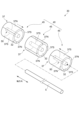
- Fig. 2 is a schematic diagram of a rotor 30 according to an embodiment of the present disclosure.
- Fig. 3 is a schematic diagram of an iron core unit 40 according to an embodiment of the present disclosure.
- the above-mentioned iron core unit 40 which is a component of the rotor 30, includes multiple iron core blocks 45 stacked in the axial direction, and each iron core block 45 is supported by the rotating shaft 5.
- Each iron core block 45 includes an iron core 32 and multiple magnets 37 arranged on the iron core 32 in a circumferential line.
- Each iron core 32 may be composed of electromagnetic steel sheets stacked in the axial direction, or may be composed of a powder magnetic core extending in the axial direction, or may be composed of a combination of these.
- the multiple magnets 37 are multiple south pole magnets 37S and north pole magnets 37N arranged alternately in the circumferential direction. All of the multiple magnets 37 that make up the iron core unit 40 have the same circumferential length.
- the total number of magnets 37 constituting the iron core unit 40 is the sum of the number of south pole magnets 37S and north pole magnets 37N arranged in each iron core block 45 multiplied by the number of iron core blocks 45.
- the number of iron core blocks 45 is three, and the number of magnets 37 in each iron core block 45 is four. Therefore, the total number of magnets 37 is 12.
- the arrangement of the magnets 37 differs between at least two of the multiple iron core blocks 45 that are adjacent in the axial direction. More specifically, each of the multiple S-pole magnets 37S constituting one adjacent iron core block 45 overlaps in the circumferential direction with one of the multiple N-pole magnets 37N constituting the other adjacent iron core block 45.
- a specific S-pole magnet 37S and a specific N-pole magnet 37N overlap in the circumferential direction means that at least a portion of the circumferential range in which the S-pole magnet 37S is arranged overlaps with the circumferential range in which the N-pole magnet 37N is arranged.
- the above-mentioned magnet arrangement relationship between two adjacent iron core blocks 45 may be referred to as a "magnet misalignment relationship.”
- the central core block 45 has a magnet misalignment relationship with each of the core blocks 45 on either side. Furthermore, in any two adjacent core blocks 45 out of the three core blocks 45, the amount of circumferential overlap (dimension P in Figure 3) between the south pole magnet 37S and the north pole magnet 37N is equal. In this example, dimension P is half the circumferential length of each magnet 37.
- the two iron core blocks 45 on both sides are also misaligned with respect to the arrangement of the magnets. More specifically, the circumferential range in which the south pole magnets 37S of one iron core block 45 are arranged coincides with the circumferential range in which the north pole magnets 37N of the other iron core block 45 are arranged.
- the rotating shaft 5 is inserted into an insertion hole 50 formed in the center of each of the multiple iron core blocks 45.
- an insertion hole 50 is formed in the center of each iron core 32.
- the rotating shaft 5 and the multiple iron core blocks 45 are spline-coupled. The configuration for achieving the spline coupling is omitted in FIGS. 1 to 3, and will be described later using FIGS. 4, 5, etc.
- the rotor 30 shown in FIG. 2 has a surface permanent magnet (SPM) configuration in which multiple magnets 37 are provided on the outer circumferential surface of the iron core 32, but the present disclosure is not limited to this.
- Rotors 30 in other examples may have an interior permanent magnet (IPM) configuration in which multiple magnets 37 are embedded in the iron core 32. Detailed illustrations are omitted in this document.
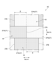
- FIG. 4 is a schematic diagram of a rotating shaft 5 according to an embodiment of the present disclosure.
- Fig. 5 is a schematic diagram of an iron core unit 40 according to an embodiment of the present disclosure.
- the spline connection between the rotating shaft 5 and each iron core block 45 is realized by meshing a plurality of teeth 70 (see Fig. 4) provided on the rotating shaft 5 with a plurality of recesses 80 (see Fig. 5) provided on each iron core block 45.
- the details are as follows.
- the rotating shaft 5 includes an outer peripheral surface 15 and a plurality of teeth 70 arranged at equal intervals in the circumferential direction on the outer peripheral surface 15.
- Each tooth 70 is formed over the entire axial length of the rotating shaft 5 (see FIG. 7).
- a plurality of recesses 80 are provided in each core block 45.
- an inner peripheral surface 51 that defines the insertion hole 50 is formed in each core 32, and a plurality of recesses 80 are formed in this inner peripheral surface 51.
- the number of recesses 80 is the same as the number of tooth portions 70, and the pitch of the recesses 80 is also the same as the pitch of the tooth portions 70.
- the plurality of tooth portions 70 are engaged with the plurality of recesses 80 in each core block 45. This realizes a spline connection between the rotating shaft 5 and each core block 45.
- the iron core unit 40 has the magnet misalignment relationship described above. Therefore, the multiple iron core blocks 45 are spline-connected to the rotating shaft 5 with the phases of at least two axially adjacent iron core blocks 45 shifted from each other so that they have a magnet misalignment relationship.
- the multiple core blocks 45 have the same shape. That is, the circumferential positional relationship between the multiple recesses 80 and the multiple magnets 37 is the same for each core block 45. Therefore, if the core blocks 45 are lined up in the axial direction before assembling the core unit 40 so that the magnets 37 are aligned in the circumferential direction (see the upper part of Figure 6), the circumferential range in which the multiple recesses 80 are arranged is the same for each core block 45.
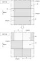
- FIG. 6 is a schematic diagram showing an assembly process of the rotor 30 according to an embodiment of the present disclosure.
- Fig. 7 is a schematic diagram showing an assembly process of the rotor 30 following Fig. 6.
- the assembly method of the rotor 30 according to an embodiment of the present disclosure is as follows.
- multiple core blocks 45 are aligned in the axial direction.
- the phases of the multiple core blocks 45 may be aligned with each other.
- the multiple core blocks 45 may be aligned in the axial direction so that the arrangement of the magnets 37 is aligned in the circumferential direction.
- the phase of one of the core blocks 45 is shifted by one pitch of the recesses 80 to create a magnet misalignment relationship between two axially adjacent core blocks 45 (see the lower part of Figure 6).
- the amount of shift of one pitch of the recesses 80 corresponds to dimension P in Figures 5 and 6. Even when a magnet misalignment relationship is created, the circumferential range in which the recesses 80 are arranged is the same for each core block 45.
- the rotating shaft 5 is inserted into the insertion hole 50 of each iron core block 45 (see FIG. 7).
- the rotating shaft 5 is spline-coupled to each iron core block 45, and the rotor 30 is assembled.
- the above assembly may be performed by an operator, a robot arm operated by an operator, or a combination of these.
- the phase difference between the multiple iron core blocks 45 may be two or three pitches of the recesses 80, for example.
- the rotating shaft 5 and the core unit 40 are spline-coupled, which makes it possible to prevent the core unit 40 from shifting circumferentially relative to the rotating shaft 5 during operation of the rotor 30. Furthermore, in the assembly process of the rotor 30, the rotor 30 and the core unit 40 can be spline-coupled simply by inserting the rotating shaft 5 into the core blocks 45 in a state in which a phase difference occurs between two adjacent core blocks. As described above, a rotor 30 (rotating electric machine 1) is realized that can easily generate a phase difference between the core blocks 45 during the assembly process and can prevent the core unit 40 from shifting circumferentially relative to the rotating shaft 5 during operation.
- the number of recesses 80 in each core block 45 may be different from the number of magnets 37 in each core block 45. According to the above configuration, in the assembly process of the rotor 30, the recesses 80 and the teeth 70 are meshed with each other, thereby creating a phase difference between two adjacent core blocks 45. In the example of the figure, the number of the recesses 80 in each core block 45 is greater than the number of the magnets 37 in each core block 45. As an example, the number of recesses 80 is eight, and the total number of the S pole magnets 37S and the N pole magnets 37N in each core block 45 is four.
- the phase difference that can be provided between two adjacent core blocks 45 is a value obtained by multiplying the pitch of the recesses 80 by a natural number. According to the above configuration, the number of recesses 80 increases, so the pitch of the recesses 80 can be made smaller. Therefore, in the assembly process of the rotor 30, the phase difference between adjacent core blocks 45 (dimension P shown in the lower part of FIG. 6) can be adjusted more finely.
- the core unit 40 may have a skew structure in which the circumferential position of the magnet boundary 37B formed between adjacent south pole magnets 37S and north pole magnets 37N differs between two axially adjacent core blocks 45.
- the multiple core blocks 45 may have the same shape. With the above configuration, the mass productivity of the core blocks 45 can be improved. In this embodiment, the positional relationship between the multiple recesses 80 and the multiple magnets 37 in the circumferential direction is the same for each core block 45.
- FIG. 8 is a schematic diagram of an iron core unit 40A according to another embodiment of the present disclosure.
- Each iron core block 45A of the iron core unit 40A includes a connecting member 60 that is connected to the iron core 32 and the rotating shaft 5.
- the connecting member 60 is cylindrical and extends in the axial direction, and is press-fitted into the fitting hole 33 formed in the iron core 32.
- the connecting member 60 is formed of a magnetic metal material, and more specifically, of a metal material containing iron as a component.
- the insertion hole 50 is formed in the connecting member 60. That is, the above-mentioned multiple recesses 80 are formed in the inner circumferential surface 51 provided in the connecting member 60.
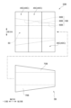
- FIG. 9 is a schematic diagram showing a rotor 30A according to another embodiment of the present disclosure.
- the rotor 30A includes a rotating shaft 5A and a plurality of iron core blocks 45B.
- Each of the plurality of teeth 70A constituting the rotating shaft 5A has a tapered shape in which the circumferential length gradually increases from one side to the other side in the axial direction.
- the multiple recesses 80A that make up each core block 45B have a tapered shape in which the circumferential length gradually increases from one axial side to the other. Furthermore, the shape of the recesses 80A differs between the multiple core blocks 45B. More specifically, the recess group 88, which is the axially aligned recesses 80A that make up the core unit 40A, has a tapered shape in which the circumferential length gradually increases from one axial side to the other.
- the rotating shaft 5A is inserted into the insertion hole 50 while moving it from the other side to one side in the axial direction, so that the multiple teeth 70A fit into the multiple recesses 80A of each core block 45B.
- the circumferential length of the recesses 80A on the other side of the axial direction is relatively long, the task of inserting the teeth 70A into the recesses 80A is easy. Therefore, contact between the multiple teeth 70A and the multiple recesses 80A can be avoided, improving the assembly of the rotor 30A.
- FIG. 10 is a schematic diagram showing a rotor 30B according to another embodiment of the present disclosure.
- the rotor 30B includes a rotating shaft 5B and an iron core unit 40C including a plurality of iron core blocks 45C.
- Each of the plurality of teeth 70B constituting the rotating shaft 5B has a tapered shape in which the radial length (height) gradually decreases from one side to the other side in the axial direction.
- the multiple recesses 80B that make up each core block 45C have a tapered shape in which the radial length (depth) gradually decreases from one side to the other in the axial direction. Furthermore, the shape of the recesses 80B differs between the multiple core blocks 45C. More specifically, the recess group 188, which is the axially aligned recesses 80B that make up the core unit 40, has a tapered shape in which the radial length gradually decreases from one side to the other in the axial direction.
- the rotating shaft 5B is inserted into the insertion hole 50 while moving it from the other side to one side in the axial direction, so that the multiple teeth 70B fit into the multiple recesses 80B of each core block 45C.
- the radial length of the recesses 80B on the other side in the axial direction is relatively short, the task of inserting the teeth 70B into the recesses 80B is easy. Therefore, contact between the multiple teeth 70B and the multiple recesses 80B can be avoided, improving the ease of assembly of the rotor 30B.
- the rotating electric machine 1 may be a magnetic gear electric machine.
- the rotating electric machine 1 further includes a pole piece rotor configured to rotate relative to the rotor 30.
- the pole piece rotor includes a plurality of pole pieces arranged in the circumferential direction between the plurality of magnets 37 and the plurality of stator magnets 29, a pair of end plates supporting both ends in the axial direction of each pole piece, and a pole piece rotating shaft to which the pair of end plates are fixed.
- the pair of end plates are arranged on both sides in the axial direction of the rotor 30.
- the pole piece rotating shaft is arranged coaxially with the rotating shaft 5 and is connected to the external device 7 instead of the rotating shaft 5.
- the magnetic gear electric machine having the above configuration may be a magnetic gear motor that drives the external device 7 by power supply from the power system 6, or may be a magnetic gear generator that supplies power from the stator coil 27 to the power system 6 by torque input from the external device 7.
- the rotor (30, 30A, 30B) has A rotating shaft (5, 5A, 5B), an iron core unit (40, 40A, 40C) supported by the rotating shaft and including a plurality of iron core blocks (45, 45A, 45B, 45C) stacked in an axial direction of the rotating shaft; Equipped with Each of the plurality of core blocks includes An iron core (32); A plurality of S-pole magnets (37S) and a plurality of N-pole magnets (37N) arranged on the iron core in an alternating manner in the circumferential direction; Including, The rotating shaft includes a plurality of teeth (70, 70A, 70B) arranged in the circumferential direction, Each of the plurality of core blocks includes a plurality of recesses (80, 80A, 80B) that mesh with the plurality of teeth, The multiple core blocks are spline-connected to the rotating shaft with the phases shifted from each other so that each of the multiple S-pole magnets of an adjacent core
- the rotating shaft and the core unit are spline-coupled, which makes it possible to prevent the core unit from shifting circumferentially relative to the rotating shaft during rotor operation. Furthermore, in the rotor assembly process, the rotor and the core unit can be spline-coupled simply by inserting the rotating shaft into the core blocks in a state where a phase difference occurs between two adjacent core blocks. As described above, a rotor is realized that can easily generate a phase difference between the core blocks during the assembly process, and can prevent the core unit from shifting circumferentially relative to the rotating shaft during operation.
- the rotor according to 1) above The number of the recesses in each of the core blocks is different from the total number of the south pole magnets and the north pole magnets in each of the core blocks.
- the core unit has a skew structure in which the circumferential position of a magnet boundary formed between adjacent S-pole magnets and N-pole magnets differs between two adjacent core blocks.
- the configuration of 3) above allows for more uniform distribution of magnetic flux around the rotor. Therefore, in an embodiment in which the rotor is incorporated in a motor, for example, pulsation in the output torque can be suppressed.
- Each of the plurality of core blocks further includes a connecting member (60) that is connected to the core and the rotating shaft, The plurality of recesses are formed in each of the connecting members.
- the configuration of 4) above eliminates the need to process the core to form the recesses, which helps to avoid damage to the core. This helps to prevent the core from being discarded due to damage, and helps to prevent increases in rotor costs.
- Each of the plurality of tooth portions is configured to have a circumferential length that increases from one side to the other side in the axial direction
- a group of recesses (88) which are a plurality of recesses arranged in the axial direction and which constitute the core unit are configured so that the circumferential length increases from one side to the other side in the axial direction.
- the rotating shaft is inserted into the core unit while moving it from one side to the other in the axial direction, which makes it possible to avoid contact between the multiple teeth and the multiple recesses. Since it is easier to insert the rotating shaft, the assembly of the rotor is improved.
- each of the plurality of tooth portions is configured to have a radial length that becomes shorter from one side to the other side in the axial direction
- a group of recesses (188) which are a plurality of recesses arranged in the axial direction and which constitute the core unit are configured so that their radial length becomes shorter going from one side to the other side in the axial direction.
- the rotating shaft is inserted into the core unit while moving it from the other side to one side in the axial direction, which makes it possible to avoid contact between the multiple teeth and the multiple recesses. Since it becomes easier to insert the rotating shaft, the assembly of the rotor is improved.
- the rotor according to any one of 1) to 4) above, The core blocks have the same shape.
- the configuration 7) above can improve the mass productivity of the core block.
- a rotating electric machine (1) according to at least one embodiment of the present disclosure, A rotor (30, 30A) according to any one of 1) to 7) above; and a stator (20) provided radially outward of the rotor.
Landscapes
- Engineering & Computer Science (AREA)
- Power Engineering (AREA)
- Iron Core Of Rotating Electric Machines (AREA)
- Permanent Field Magnets Of Synchronous Machinery (AREA)
Abstract
回転子は、回転軸と回転軸によって支持される複数の鉄心ブロックとを備える。回転軸は、周方向に並ぶ複数の歯部を含む。複数の鉄心ブロックの各々は、複数の歯部とそれぞれ噛み合う複数の凹部を含む。複数の鉄心ブロックは、隣接する一方の鉄心ブロックの複数のS極磁石の各々が隣接する他方の鉄心ブロックのいずれかのN極磁石と周方向に重なるように互いに位相がずらされた状態で、回転軸にスプライン結合されている。
Description
本開示は、回転子、および、回転電気機械に関する。
本願は、2023年1月18日に日本国特許庁に出願された特願2023-005799号に基づき優先権を主張し、その内容をここに援用する。
本願は、2023年1月18日に日本国特許庁に出願された特願2023-005799号に基づき優先権を主張し、その内容をここに援用する。
従来、回転電気機械に組込まれる回転子が知られている。例えば、特許文献1では、車両用モータとして使用される回転電気機械に搭載された回転子が開示される。回転子は、回転軸が篏合される回転子コアと、回転子コアに設けられる複数の磁石とを備えている。
発明者の知見によれば、回転子コアが軸方向に並ぶ複数のコアブロックによって形成され、かつ、隣接するコアブロックの間で磁石の配置を変えれば、回転子全体の周囲における磁束の分布は、磁石の配置を変えない場合に比べて、周方向においてより均等になる。その結果、複数のコアブロックにより形成される回転子コアにおけるトルクは、周方向においてより均等になり、トルクリップルが抑制される。こういった回転子の組立は容易に行われることが好ましい。また、回転子の動作時に回転子コアが回転軸に対して周方向にずれるのを抑制することが好ましい。
本開示の目的は、複数の鉄心ブロックの間における位相差を組立工程において容易に生じさせることができると共に、動作中に鉄心ユニットが回転軸に対して周方向にずれるのを抑制できる回転子、および、回転電気機械を提供することである。
本開示の少なくとも一実施形態に係る回転子は、
回転軸と、
前記回転軸によって支持される鉄心ユニットであって、前記回転軸の軸方向に積層される複数の鉄心ブロックを含む鉄心ユニットと、
を備え、
前記複数の鉄心ブロックの各々は、
鉄心と、
周方向に交互に並ぶようにして前記鉄心に配置される複数のS極磁石および複数のN極磁石と、
を含み、
前記回転軸は、前記周方向に並ぶ複数の歯部を含み、
前記複数の鉄心ブロックの各々は、前記複数の歯部とそれぞれ噛み合う複数の凹部を含み、
前記複数の鉄心ブロックは、隣接する一方の前記鉄心ブロックの前記複数のS極磁石の各々が隣接する他方の前記鉄心ブロックのいずれかの前記N極磁石と前記周方向に重なるように互いに位相がずらされた状態で、前記回転軸にスプライン結合されている。
回転軸と、
前記回転軸によって支持される鉄心ユニットであって、前記回転軸の軸方向に積層される複数の鉄心ブロックを含む鉄心ユニットと、
を備え、
前記複数の鉄心ブロックの各々は、
鉄心と、
周方向に交互に並ぶようにして前記鉄心に配置される複数のS極磁石および複数のN極磁石と、
を含み、
前記回転軸は、前記周方向に並ぶ複数の歯部を含み、
前記複数の鉄心ブロックの各々は、前記複数の歯部とそれぞれ噛み合う複数の凹部を含み、
前記複数の鉄心ブロックは、隣接する一方の前記鉄心ブロックの前記複数のS極磁石の各々が隣接する他方の前記鉄心ブロックのいずれかの前記N極磁石と前記周方向に重なるように互いに位相がずらされた状態で、前記回転軸にスプライン結合されている。
本開示の少なくとも一実施形態に係る回転電気機械は、
上記回転子と、
前記回転子よりも径方向の外側に設けられる固定子と
を備える。
上記回転子と、
前記回転子よりも径方向の外側に設けられる固定子と
を備える。
本開示によれば、複数の鉄心ブロックの間における位相差を組立工程において容易に生じさせることができると共に、動作中に鉄心ユニットが回転軸に対して周方向にずれるのを抑制できる回転子、および、回転電気機械を提供できる。
以下、添付図面を参照して本開示の幾つかの実施形態について説明する。ただし、実施形態として記載されている又は図面に示されている構成部品の寸法、材質、形状、その相対的配置等は、本開示の範囲をこれに限定する趣旨ではなく、単なる説明例にすぎない。
例えば、「ある方向に」、「ある方向に沿って」、「平行」、「直交」、「中心」、「同心」或いは「同軸」等の相対的或いは絶対的な配置を表す表現は、厳密にそのような配置を表すのみならず、公差、若しくは、同じ機能が得られる程度の角度や距離をもって相対的に変位している状態も表すものとする。
例えば、「同一」、「等しい」及び「均質」等の物事が等しい状態であることを表す表現は、厳密に等しい状態を表すのみならず、公差、若しくは、同じ機能が得られる程度の差が存在している状態も表すものとする。
例えば、四角形状や円筒形状等の形状を表す表現は、幾何学的に厳密な意味での四角形状や円筒形状等の形状を表すのみならず、同じ効果が得られる範囲で、凹凸部や面取り部等を含む形状も表すものとする。
一方、一の構成要素を「備える」、「含む」、又は、「有する」という表現は、他の構成要素の存在を除外する排他的な表現ではない。
なお、同様の構成については同じ符号を付し説明を省略することがある。
例えば、「ある方向に」、「ある方向に沿って」、「平行」、「直交」、「中心」、「同心」或いは「同軸」等の相対的或いは絶対的な配置を表す表現は、厳密にそのような配置を表すのみならず、公差、若しくは、同じ機能が得られる程度の角度や距離をもって相対的に変位している状態も表すものとする。
例えば、「同一」、「等しい」及び「均質」等の物事が等しい状態であることを表す表現は、厳密に等しい状態を表すのみならず、公差、若しくは、同じ機能が得られる程度の差が存在している状態も表すものとする。
例えば、四角形状や円筒形状等の形状を表す表現は、幾何学的に厳密な意味での四角形状や円筒形状等の形状を表すのみならず、同じ効果が得られる範囲で、凹凸部や面取り部等を含む形状も表すものとする。
一方、一の構成要素を「備える」、「含む」、又は、「有する」という表現は、他の構成要素の存在を除外する排他的な表現ではない。
なお、同様の構成については同じ符号を付し説明を省略することがある。
<1.回転電気機械1の概要>
図1は、本開示の一実施形態に係る回転子30を備えた回転電気機械1の概略図である。回転子30は回転軸5を備えており、回転軸5は外部機器7に連結される。外部機器7は回転軸5と継手を介して連結されてもよいし、歯車を介して連結されてもよい。本実施形態では、外部機器7は車両であり、回転電気機械1は車両用モータである。そして、回転軸5が外部機器7のドライブシャフトに継手を介して連結されている。
図1は、本開示の一実施形態に係る回転子30を備えた回転電気機械1の概略図である。回転子30は回転軸5を備えており、回転軸5は外部機器7に連結される。外部機器7は回転軸5と継手を介して連結されてもよいし、歯車を介して連結されてもよい。本実施形態では、外部機器7は車両であり、回転電気機械1は車両用モータである。そして、回転軸5が外部機器7のドライブシャフトに継手を介して連結されている。
以下の説明では、回転軸5の軸方向を単に「軸方向」という場合がある。また、軸方向を基準とした周方向および径方向を、それぞれ単に「周方向」および「径方向」という場合がある。
回転電気機械1は、ハウジング9と、ハウジング9によって回転可能に支持される回転子30とを備える。回転子30は、一対のベアリングB1を介してハウジング9に連結される回転軸5と、回転軸5によって支持される鉄心ユニット40とを備える。本実施形態の鉄心ユニット40は、軸方向に積層される複数の鉄心ブロック45を含み、各鉄心ブロック45に、周方向に並ぶ複数の磁石37が配置されている。各鉄心ブロック45は回転軸5にスプライン結合されている(詳細は後述する)。従って、鉄心ユニット40は回転軸5と共に回転するようになっている。
回転電気機械1は、ハウジング9に固定される固定子20をさらに備える。回転子30よりも径方向の外側に配置される固定子20は、ステータコア25と、ステータコア25に設けられる複数のステータ磁石29と、ステータコア25に巻かれたステータコイル27とを含む。ステータコイル27は、電力系統6に電気的に接続されている。
モータとしての回転電気機械1は、電力系統6からの電力の供給によって、外部機器7を駆動する。より具体的には、ステータコイル27において電流が流れることで発生する回転磁界によって、回転子30が回転軸5と共に回転する。これにより、回転軸5から外部機器7にトルクが伝達されて、外部機器7は駆動される。
<2.回転子30の構成の詳細>
図2は、本開示の一実施形態に係る回転子30の概略図である。図3は、本開示の一実施形態に係る鉄心ユニット40の概略図である。
図2は、本開示の一実施形態に係る回転子30の概略図である。図3は、本開示の一実施形態に係る鉄心ユニット40の概略図である。
回転子30の構成要素である上述の鉄心ユニット40は、軸方向に積層された複数の鉄心ブロック45を含み、各鉄心ブロック45は回転軸5によって支持される。各鉄心ブロック45は、鉄心32と、周方向に並ぶようにして鉄心32に配置される複数の磁石37とを含む。各々の鉄心32は、軸方向に積層された電磁鋼板によって構成されてもよいし、軸方向に延在する圧粉磁心によって構成されてもよいし、または、これらの組み合わせによって構成されてもよい。複数の磁石37は、周方向に交互に並ぶようにして配置される複数のS極磁石37SおよびN極磁石37Nである。なお、鉄心ユニット40を構成する複数の磁石37はいずれも、互いに同じ周方向長さを有する。
鉄心ユニット40を構成する磁石37の総数は、1つ当たりの鉄心ブロック45に配置されるS極磁石37SおよびN極磁石37Nの合計数に、鉄心ブロック45の個数を乗じた値である。図2で一例として図示される実施形態では、鉄心ブロック45の個数は3個であり、各鉄心ブロック45における磁石37の個数は4個である。従って、磁石37の総数は12個である。
本実施形態では、複数の鉄心ブロック45のうちで少なくとも軸方向に隣接する2つの鉄心ブロック45の間では、磁石37の配置が異なる。より詳細には、隣接する一方の鉄心ブロック45を構成する複数のS極磁石37Sは各々、隣接する他方の鉄心ブロック45を構成する複数のN極磁石37Nとのいずれかと周方向に重なる。ここで、特定のS極磁石37Sと特定のN極磁石37Nが周方向に重なるとは、S極磁石37Sが配置される周方向範囲の少なくとも一部が、N極磁石37Nが配置される周方向範囲と重なることである。以下、隣接する2つの鉄心ブロック45が有する上述のような磁石配置の関係を、「磁石の配置ずれの関係」と表記する場合がある。
中央の鉄心ブロック45は、両側にある各々の鉄心ブロック45と、磁石の配置ずれの関係を有する。また、3個の鉄心ブロック45のうち隣接する任意の2つの鉄心ブロック45において、S極磁石37SとN極磁石37Nとの周方向における重なり量(図3の寸法P)はいずれも等しい。本例の寸法Pは、各磁石37の周方向長さの半分である。
本実施形態では、両側にある2つの鉄心ブロック45も、互いに磁石の配置ずれの関係にある。より詳細には、一方の鉄心ブロック45が有する各々のS極磁石37Sが配置される周方向範囲は、他方の鉄心ブロック45が有する各々のN極磁石37Nが配置される周方向範囲と一致する。
図2で例示されるように、回転軸5は、複数の鉄心ブロック45の各々の中央部に形成された差込孔50に差し込まれている。図2では一例として、差込孔50が各々の鉄心32の中央部に形成されている。本実施形態では、回転軸5と複数の鉄心ブロック45はスプライン結合する。スプライン結合を実現するための構成は、図1~図3では省略されており、図4、図5などを用いて後述する。
なお、図2で示される回転子30は、鉄心32の外周面に複数の磁石37が設けられる表面磁石型(SPM;Surface Permanent Magnet)の構成を有するが、本開示はこれに限定されない。他の例に係る回転子30は、複数の磁石37が鉄心32に埋め込まれる埋込磁石型(IPM;Interior Permanent Magnet)の構成を有してもよい。本稿では詳細な図示を省略する。
<3.回転軸5と鉄心ブロック45のスプライン結合>
図4は、本開示の一実施形態に係る回転軸5の概略図である。図5は、本開示の一実施形態に係る鉄心ユニット40の概略図である。回転軸5と各鉄心ブロック45とのスプライン結合は、回転軸5に設けられる複数の歯部70(図4参照)と、各鉄心ブロック45に設けられる複数の凹部80(図5参照)とが噛み合うことで実現される。詳細は以下の通りである。
図4は、本開示の一実施形態に係る回転軸5の概略図である。図5は、本開示の一実施形態に係る鉄心ユニット40の概略図である。回転軸5と各鉄心ブロック45とのスプライン結合は、回転軸5に設けられる複数の歯部70(図4参照)と、各鉄心ブロック45に設けられる複数の凹部80(図5参照)とが噛み合うことで実現される。詳細は以下の通りである。
図4で例示されるように、回転軸5は、外周面15と、外周面15において周方向に等間隔に並ぶ複数の歯部70を含む。各歯部70は、回転軸5の軸方向長さの全長に亘って形成される(図7参照)。図5で例示されるように、複数の凹部80は、各々の鉄心ブロック45に設けられる。より具体的な一例として、差込孔50を規定する内周面51が各鉄心32に形成されており、この内周面51に複数の凹部80が形成されている。凹部80の個数は歯部70の個数と同じであり、凹部80のピッチと歯部70のピッチも同じである。複数の歯部70は、各鉄心ブロック45における複数の凹部80とそれぞれ噛み合っている。これにより、回転軸5と各鉄心ブロック45とのスプライン結合は実現される。
鉄心ユニット40には上述した磁石の配置ずれの関係がある。従って、複数の鉄心ブロック45は、少なくとも軸方向に隣接する2つの鉄心ブロック45が磁石の配置ずれの関係を有するように互いに位相がずらされた状態で、回転軸5にスプライン結合されている。
本実施形態では、複数の鉄心ブロック45は互いに同じ形状を呈する。即ち、複数の凹部80と複数の磁石37との周方向における位置関係は、どの鉄心ブロック45においても同じである。従って、鉄心ユニット40の組立前に磁石37の配置が周方向に揃うようにして鉄心ブロック45を軸方向に並べた場合(図6の上段参照)、複数の凹部80が配置される周方向範囲は、どの鉄心ブロック45においても同じである。
<4.回転子30の組立方法>
図6は、本開示の一実施形態に係る回転子30の組立工程を示す概略図である。図7は、図6に続く、回転子30の組立工程を示す概略図である。本開示の一実施形態に係る回転子30の組立方法は、以下の通りである。
図6は、本開示の一実施形態に係る回転子30の組立工程を示す概略図である。図7は、図6に続く、回転子30の組立工程を示す概略図である。本開示の一実施形態に係る回転子30の組立方法は、以下の通りである。
はじめに、図6の上段で示すように、複数の鉄心ブロック45を軸方向に並べる。このとき、複数の鉄心ブロック45の位相は互いに揃えられていてもよい。つまり、磁石37の配置が周方向に揃うよう複数の鉄心ブロック45は軸方向に並べられてもよい。
その後、いずれかの鉄心ブロック45の位相を複数の凹部80の1ピッチ分ずらすことで、軸方向に隣接する2つの鉄心ブロック45の間で磁石の配置ずれの関係を作る(図6の下段参照)。凹部80の1ピッチ分のずらし量は、図5、および、図6下段の寸法Pに該当する。磁石の配置ずれの関係が作られたときも、複数の凹部80が配置される周方向範囲は、どの鉄心ブロック45においても同じである。
さらにその後、回転軸5が各鉄心ブロック45の差込孔50に差し込まれる(図7参照)。これにより、回転軸5は各鉄心ブロック45とスプライン結合され、回転子30が組み上がる。上記組立は、作業者によって行われてもよいし、作業者が操作するロボットアームによって行われてもよいし、または、これらの組み合わせによって行われてもよい。また、複数の鉄心ブロック45の間でつける位相差は、凹部80の2ピッチ分または3ピッチ分などであってもよい。
以上説明した回転子30の構成によれば、回転軸5と鉄心ユニット40とがスプライン結合するので、回転子30の動作中に鉄心ユニット40が回転軸5に対して周方向にずれるのを抑制できる。また、回転子30の組立工程では、隣接する2つの鉄心ブロックの間で位相差が生じる状態で回転軸5を複数の鉄心ブロック45に差し込みさえすれば、回転子30と鉄心ユニット40とをスプライン結合させることができる。以上より、複数の鉄心ブロック45の間における位相差を組立工程において容易に生じさせることができると共に、動作中に鉄心ユニット40が回転軸5に対して周方向にずれるのを抑制できる回転子30(回転電気機械1)が実現される。
<5.回転子30の追加的な構成>
図5で示す通り、各鉄心ブロック45における複数の凹部80の個数は、各々の鉄心ブロック45における複数の磁石37の個数とは異なってもよい。上記構成によれば、回転子30の組立工程において、複数の凹部80と複数の歯部70とを噛み合わせることで、互いに隣接する2つの鉄心ブロック45の間で位相差をつけることができる。
同図の例では、各鉄心ブロック45における複数の凹部80の個数は、各々の鉄心ブロック45における複数の磁石37の個数よりも多い。一例として凹部80の個数は8個であり、各鉄心ブロック45における複数のS極磁石37Sおよび複数のN極磁石37Nの合計の個数は4個である。回転子30の組立工程において、互いに隣接する2つの鉄心ブロック45の間でつけることができる位相差は、複数の凹部80のピッチに自然数を乗じた値である。上記構成によれば、凹部80の個数が増えるので、凹部80のピッチを小さくできる。従って、回転子30の組立工程において、隣接する鉄心ブロック45の間における位相差(図6の下段で示す寸法P)をより微細に調整できる。
図5で示す通り、各鉄心ブロック45における複数の凹部80の個数は、各々の鉄心ブロック45における複数の磁石37の個数とは異なってもよい。上記構成によれば、回転子30の組立工程において、複数の凹部80と複数の歯部70とを噛み合わせることで、互いに隣接する2つの鉄心ブロック45の間で位相差をつけることができる。
同図の例では、各鉄心ブロック45における複数の凹部80の個数は、各々の鉄心ブロック45における複数の磁石37の個数よりも多い。一例として凹部80の個数は8個であり、各鉄心ブロック45における複数のS極磁石37Sおよび複数のN極磁石37Nの合計の個数は4個である。回転子30の組立工程において、互いに隣接する2つの鉄心ブロック45の間でつけることができる位相差は、複数の凹部80のピッチに自然数を乗じた値である。上記構成によれば、凹部80の個数が増えるので、凹部80のピッチを小さくできる。従って、回転子30の組立工程において、隣接する鉄心ブロック45の間における位相差(図6の下段で示す寸法P)をより微細に調整できる。
図3で示す通り、鉄心ユニット40は、隣接するS極磁石37SとN極磁石37Nの間に形成される磁石境界37Bの周方向位置が、軸方向に隣接する2つの鉄心ブロック45の間で異なるスキュー構造を有してもよい。上記構成によれば、回転子30全体の周囲における磁束の分布を周方向においてより均等化することができる。従って、モータとしての回転電気機械1は出力トルクの脈動を抑制できる。
また、複数の鉄心ブロック45は互いに同じ形状を呈してもよい。上記構成によれば、鉄心ブロック45の量産性を向上させることができる。なお、このような実施形態では、複数の凹部80と複数の磁石37との周方向における位置関係は、どの鉄心ブロック45においても同じである。
<6.本開示の他の実施形態>
図8は、本開示の他の実施形態に係る鉄心ユニット40Aの概略図である。鉄心ユニット40Aの各鉄心ブロック45Aは、鉄心32と回転軸5とに連結される連結部材60を備える。連結部材60は軸方向に延在する円筒状であり、鉄心32に形成される篏合孔33に圧入されている。連結部材60は一例として磁性を有する金属材料によって形成され、より具体的には鉄を成分として含む金属材料によって形成される。図8の例では、差込孔50は連結部材60に形成されている。即ち、連結部材60に設けられた内周面51に、上述の複数の凹部80が形成されている。上記構成によれば、凹部80を形成するための加工を鉄心32に施す必要がないので、鉄心32の損傷を回避できる。これにより、鉄心32の損傷に起因した鉄心32の廃棄を抑制でき、回転子30のコスト増大を抑制できる。
図8は、本開示の他の実施形態に係る鉄心ユニット40Aの概略図である。鉄心ユニット40Aの各鉄心ブロック45Aは、鉄心32と回転軸5とに連結される連結部材60を備える。連結部材60は軸方向に延在する円筒状であり、鉄心32に形成される篏合孔33に圧入されている。連結部材60は一例として磁性を有する金属材料によって形成され、より具体的には鉄を成分として含む金属材料によって形成される。図8の例では、差込孔50は連結部材60に形成されている。即ち、連結部材60に設けられた内周面51に、上述の複数の凹部80が形成されている。上記構成によれば、凹部80を形成するための加工を鉄心32に施す必要がないので、鉄心32の損傷を回避できる。これにより、鉄心32の損傷に起因した鉄心32の廃棄を抑制でき、回転子30のコスト増大を抑制できる。
図9は、本開示の他の実施形態に係る回転子30Aを示す概略図である。回転子30Aは、回転軸5Aと、複数の鉄心ブロック45Bとを備える。回転軸5Aを構成する複数の歯部70Aの各々は、軸方向の一方側から他方側に向かうにつれて周方向長さが徐々に長くなるテーパ形状を呈する。
また、各々の鉄心ブロック45Bを構成する複数の凹部80Aは、軸方向の一方側から他方側に向かうにつれて周方向長さが徐々に長くなるテーパ形状を呈する。さらに、凹部80Aの形状は複数の鉄心ブロック45Bの間で異なる。より具体的には、鉄心ユニット40Aを構成する軸方向に並んだ凹部80Aである凹部群88は、軸方向の一方側から他方側に向かうにつれて周方向長さが徐々に長くなるテーパ形状を呈する。
図9の例では、回転子30Aの組立工程において、回転軸5Aを軸方向の他方側から一方側へ移動させながら差込孔50に差し込むことで、複数の歯部70Aを、各鉄心ブロック45Bの複数の凹部80Aに嵌める。このとき、軸方向の他方側において凹部80Aの周方向長さは比較的長いので、歯部70Aを凹部80Aに差し込む作業が容易である。従って、複数の歯部70Aと複数の凹部80Aとの接触を回避でき、回転子30Aの組立性は向上する。
図10は、本開示の他の実施形態に係る回転子30Bを示す概略図である。回転子30Bは、回転軸5Bと、複数の鉄心ブロック45Cを含む鉄心ユニット40Cとを備える。回転軸5Bを構成する複数の歯部70Bの各々は、軸方向の一方側から他方側に向かうにつれて径方向長さ(高さ)が徐々に短くなるテーパ形状を呈する。
また、各々の鉄心ブロック45Cを構成する複数の凹部80Bは、軸方向の一方側から他方側に向かうにつれて径方向長さ(深さ)が徐々に短くなるテーパ形状を呈する。さらに、凹部80Bの形状は複数の鉄心ブロック45Cの間で異なる。より具体的には、鉄心ユニット40を構成する軸方向に並んだ凹部80Bである凹部群188は、軸方向の一方側から他方側に向かうにつれて径方向長さが徐々に短くなるテーパ形状を呈する。
図10の例では、回転子30Bの組立工程において、回転軸5Bを軸方向の他方側から一方側へ移動させながら差込孔50に差し込むことで、複数の歯部70Bを、各鉄心ブロック45Cの複数の凹部80Bに嵌める。このとき、軸方向の他方側において凹部80Bの径方向長さは比較的短いので、歯部70Bを凹部80Bに差し込む作業が容易である。従って、複数の歯部70Bと複数の凹部80Bとの接触を回避でき、回転子30Bの組立性は向上する。
<7.その他>
回転電気機械1は、磁気ギア電気機械であってもよい。この場合、回転電気機械1は、回転子30に対して相対的に回転するように構成される磁極片回転子をさらに備える。磁極片回転子は、複数の磁石37と複数のステータ磁石29との間において周方向に並ぶ複数の磁極片と、各磁極片の軸方向における両端を支持する一対のエンドプレートと、一対のエンドプレートが固定される磁極片回転軸とを含む。一対のエンドプレートは回転子30の軸方向の両側に配置される。また、磁極片回転軸は、回転軸5と同軸になるように配置され、かつ、回転軸5に代えて外部機器7に連結される。上記構成を有する磁気ギア電気機械は、電力系統6からの電力の供給によって外部機器7を駆動する磁気ギアモータであってもよいし、外部機器7から入力されるトルクによってステータコイル27から電力系統6へ電力を供給する磁気ギア発電機であってもよい。
回転電気機械1は、磁気ギア電気機械であってもよい。この場合、回転電気機械1は、回転子30に対して相対的に回転するように構成される磁極片回転子をさらに備える。磁極片回転子は、複数の磁石37と複数のステータ磁石29との間において周方向に並ぶ複数の磁極片と、各磁極片の軸方向における両端を支持する一対のエンドプレートと、一対のエンドプレートが固定される磁極片回転軸とを含む。一対のエンドプレートは回転子30の軸方向の両側に配置される。また、磁極片回転軸は、回転軸5と同軸になるように配置され、かつ、回転軸5に代えて外部機器7に連結される。上記構成を有する磁気ギア電気機械は、電力系統6からの電力の供給によって外部機器7を駆動する磁気ギアモータであってもよいし、外部機器7から入力されるトルクによってステータコイル27から電力系統6へ電力を供給する磁気ギア発電機であってもよい。
<8.まとめ>
上述した幾つかの実施形態に記載の内容は、例えば以下のように把握される。
上述した幾つかの実施形態に記載の内容は、例えば以下のように把握される。
1)本開示の少なくとも一実施形態に係る回転子(30,30A,30B)は、
回転軸(5,5A,5B)と、
前記回転軸によって支持される鉄心ユニットであって、前記回転軸の軸方向に積層される複数の鉄心ブロック(45,45A,45B,45C)を含む鉄心ユニット(40,40A,40C)と、
を備え、
前記複数の鉄心ブロックの各々は、
鉄心(32)と、
周方向に交互に並ぶようにして前記鉄心に配置される複数のS極磁石(37S)および複数のN極磁石(37N)と、
を含み、
前記回転軸は、前記周方向に並ぶ複数の歯部(70,70A,70B)を含み、
前記複数の鉄心ブロックの各々は、前記複数の歯部とそれぞれ噛み合う複数の凹部(80,80A,80B)を含み、
前記複数の鉄心ブロックは、隣接する一方の前記鉄心ブロックの前記複数のS極磁石の各々が隣接する他方の前記鉄心ブロックのいずれかの前記N極磁石と前記周方向に重なるように互いに位相がずらされた状態で、前記回転軸にスプライン結合されている。
回転軸(5,5A,5B)と、
前記回転軸によって支持される鉄心ユニットであって、前記回転軸の軸方向に積層される複数の鉄心ブロック(45,45A,45B,45C)を含む鉄心ユニット(40,40A,40C)と、
を備え、
前記複数の鉄心ブロックの各々は、
鉄心(32)と、
周方向に交互に並ぶようにして前記鉄心に配置される複数のS極磁石(37S)および複数のN極磁石(37N)と、
を含み、
前記回転軸は、前記周方向に並ぶ複数の歯部(70,70A,70B)を含み、
前記複数の鉄心ブロックの各々は、前記複数の歯部とそれぞれ噛み合う複数の凹部(80,80A,80B)を含み、
前記複数の鉄心ブロックは、隣接する一方の前記鉄心ブロックの前記複数のS極磁石の各々が隣接する他方の前記鉄心ブロックのいずれかの前記N極磁石と前記周方向に重なるように互いに位相がずらされた状態で、前記回転軸にスプライン結合されている。
上記1)の構成によれば、回転軸と鉄心ユニットとがスプライン結合するので、回転子の動作中に鉄心ユニットが回転軸に対して周方向にずれるのを抑制できる。また、回転子の組立工程では、隣接する2つの鉄心ブロックの間で位相差が生じる状態で回転軸を複数の鉄心ブロックに差し込みさえすれば、回転子と鉄心ユニットとをスプライン結合させることができる。以上より、複数の鉄心ブロックの間における位相差を組立工程において容易に生じさせることができると共に、動作中に鉄心ユニットが回転軸に対して周方向にずれるのを抑制できる回転子が実現される。
2)幾つかの実施形態では、上記1)に記載の回転子であって、
各々の前記鉄心ブロックにおける前記複数の凹部の個数は、各々の前記鉄心ブロックにおける前記複数のS極磁石および前記複数のN極磁石の合計の個数とは異なる。
各々の前記鉄心ブロックにおける前記複数の凹部の個数は、各々の前記鉄心ブロックにおける前記複数のS極磁石および前記複数のN極磁石の合計の個数とは異なる。
上記2)の構成によれば、複数の凹部と複数の歯部とを噛み合わせることで、互いに隣接する2つの鉄心ブロックの間で位相差をつけることができる。
3)幾つかの実施形態では、上記1)または2)に記載の回転子であって、
前記鉄心ユニットは、隣接する前記S極磁石と前記N極磁石の間に形成される磁石境界の周方向位置が、隣接する2つの前記鉄心ブロックの間で異なるスキュー構造を有する。
前記鉄心ユニットは、隣接する前記S極磁石と前記N極磁石の間に形成される磁石境界の周方向位置が、隣接する2つの前記鉄心ブロックの間で異なるスキュー構造を有する。
上記3)の構成によれば、回転子の周囲における磁束の分布をより均等化することができる。従って、回転子が例えばモータに組込まれる実施形態では、出力トルクの脈動を抑制できる。
4)幾つかの実施形態では、上記1)から3)のいずれかに記載の回転子であって、
前記複数の鉄心ブロックの各々は、前記鉄心と前記回転軸とに連結される連結部材(60)をさらに含み、
前記複数の凹部は、各々の前記連結部材に形成される。
前記複数の鉄心ブロックの各々は、前記鉄心と前記回転軸とに連結される連結部材(60)をさらに含み、
前記複数の凹部は、各々の前記連結部材に形成される。
上記4)の構成によれば、凹部を形成するための加工を鉄心に施す必要がないので、鉄心の損傷を回避できる。これにより、鉄心の損傷に起因した鉄心の廃棄を抑制でき、回転子のコスト増大を抑制できる。
5)幾つかの実施形態では、上記1)から4)のいずれかに記載の回転子であって、
前記複数の歯部の各々は、前記軸方向の一方側から他方側に向かうにつれて周方向長さが長くなるように構成され、
前記鉄心ユニットを構成する前記軸方向に並ぶ複数の前記凹部である凹部群(88)は、前記軸方向の一方側から他方側に向かうにつれて周方向長さが長くなるように構成される。
前記複数の歯部の各々は、前記軸方向の一方側から他方側に向かうにつれて周方向長さが長くなるように構成され、
前記鉄心ユニットを構成する前記軸方向に並ぶ複数の前記凹部である凹部群(88)は、前記軸方向の一方側から他方側に向かうにつれて周方向長さが長くなるように構成される。
上記5)の構成によれば、軸方向の一方側から他方側に向けて回転軸を移動させながら鉄心ユニットに差し込むことで、複数の歯部と複数の凹部との接触を回避できる。回転軸の差し込みが容易になるので、回転子の組立性は向上する。
6)幾つかの実施形態では、上記1)から4)のいずれかに記載の回転子であって、
前記複数の歯部の各々は、前記軸方向の一方側から他方側に向かうにつれて径方向長さが短くなるように構成され、
前記鉄心ユニットを構成する前記軸方向に並ぶ複数の前記凹部である凹部群(188)は、前記軸方向の一方側から他方側に向かうにつれて径方向長さが短くなるように構成される。
前記複数の歯部の各々は、前記軸方向の一方側から他方側に向かうにつれて径方向長さが短くなるように構成され、
前記鉄心ユニットを構成する前記軸方向に並ぶ複数の前記凹部である凹部群(188)は、前記軸方向の一方側から他方側に向かうにつれて径方向長さが短くなるように構成される。
上記6)の構成によれば、軸方向の他方側から一方側に向けて回転軸を移動させながら鉄心ユニットに差し込むことで、複数の歯部と複数の凹部との接触を回避できる。回転軸の差し込みが容易になるので、回転子の組立性は向上する。
7)幾つかの実施形態では、上記1)から4)のいずれかに記載の回転子であって、
前記複数の鉄心ブロックは互いに同じ形状を呈する。
前記複数の鉄心ブロックは互いに同じ形状を呈する。
上記7)の構成によれば、鉄心ブロックの量産性を向上させることができる。
8)本開示の少なくとも一実施形態に係る回転電気機械(1)は、
上記1)乃至7)の何れかに記載の回転子(30,30A)と、
前記回転子よりも径方向の外側に設けられる固定子(20)と
を備える。
上記1)乃至7)の何れかに記載の回転子(30,30A)と、
前記回転子よりも径方向の外側に設けられる固定子(20)と
を備える。
上記8)の構成によれば、上記1)と同様の効果が得られる。
1 :回転電気機械
5,5A :回転軸
20 :固定子
30,30A,30B :回転子
32 :鉄心
37 :磁石
37B :磁石境界
37N :N極磁石
37S :S極磁石
40,40A :鉄心ユニット
45,45A,45B,45C :鉄心ブロック
60 :連結部材
70,70A,70B :歯部
80,80A,80B :凹部
88,188 :凹部群
5,5A :回転軸
20 :固定子
30,30A,30B :回転子
32 :鉄心
37 :磁石
37B :磁石境界
37N :N極磁石
37S :S極磁石
40,40A :鉄心ユニット
45,45A,45B,45C :鉄心ブロック
60 :連結部材
70,70A,70B :歯部
80,80A,80B :凹部
88,188 :凹部群
Claims (8)
- 回転軸と、
前記回転軸によって支持される鉄心ユニットであって、前記回転軸の軸方向に積層される複数の鉄心ブロックを含む鉄心ユニットと、
を備え、
前記複数の鉄心ブロックの各々は、
鉄心と、
周方向に交互に並ぶようにして前記鉄心に配置される複数のS極磁石および複数のN極磁石と、
を含み、
前記回転軸は、前記周方向に並ぶ複数の歯部を含み、
前記複数の鉄心ブロックの各々は、前記複数の歯部とそれぞれ噛み合う複数の凹部を含み、
前記複数の鉄心ブロックは、隣接する一方の前記鉄心ブロックの前記複数のS極磁石の各々が隣接する他方の前記鉄心ブロックのいずれかの前記N極磁石と前記周方向に重なるように互いに位相がずらされた状態で、前記回転軸にスプライン結合されている
回転子。 - 各々の前記鉄心ブロックにおける前記複数の凹部の個数は、各々の前記鉄心ブロックにおける前記複数のS極磁石および前記複数のN極磁石の合計の個数とは異なる
請求項1に記載の回転子。 - 前記鉄心ユニットは、隣接する前記S極磁石と前記N極磁石の間に形成される磁石境界の周方向位置が、隣接する2つの前記鉄心ブロックの間で異なるスキュー構造を有する
請求項1または2に記載の回転子。 - 前記複数の鉄心ブロックの各々は、前記鉄心と前記回転軸とに連結される連結部材をさらに含み、
前記複数の凹部は、各々の前記連結部材に形成される
請求項1または2に記載の回転子。 - 前記複数の歯部の各々は、前記軸方向の一方側から他方側に向かうにつれて周方向長さが長くなるように構成され、
前記鉄心ユニットを構成する前記軸方向に並ぶ複数の前記凹部である凹部群は、前記軸方向の一方側から他方側に向かうにつれて周方向長さが長くなるように構成される
請求項1または2に記載の回転子。 - 前記複数の歯部の各々は、前記軸方向の一方側から他方側に向かうにつれて径方向長さが短くなるように構成され、
前記鉄心ユニットを構成する前記軸方向に並ぶ複数の前記凹部である凹部群は、前記軸方向の一方側から他方側に向かうにつれて径方向長さが短くなるように構成される
請求項1または2に記載の回転子。 - 前記複数の鉄心ブロックは互いに同じ形状を呈する
請求項1または2に記載の回転子。 - 請求項1または2に記載の回転子と、
前記回転子よりも径方向の外側に設けられる固定子と
を備える回転電気機械。
Applications Claiming Priority (2)
| Application Number | Priority Date | Filing Date | Title |
|---|---|---|---|
| JP2023005799A JP2024101719A (ja) | 2023-01-18 | 2023-01-18 | 回転子、および、回転電気機械 |
| JP2023-005799 | 2023-01-18 |
Publications (1)
| Publication Number | Publication Date |
|---|---|
| WO2024154516A1 true WO2024154516A1 (ja) | 2024-07-25 |
Family
ID=91955811
Family Applications (1)
| Application Number | Title | Priority Date | Filing Date |
|---|---|---|---|
| PCT/JP2023/045254 Ceased WO2024154516A1 (ja) | 2023-01-18 | 2023-12-18 | 回転子、および、回転電気機械 |
Country Status (2)
| Country | Link |
|---|---|
| JP (1) | JP2024101719A (ja) |
| WO (1) | WO2024154516A1 (ja) |
Citations (3)
| Publication number | Priority date | Publication date | Assignee | Title |
|---|---|---|---|---|
| JP2004260918A (ja) * | 2003-02-26 | 2004-09-16 | Fujitsu General Ltd | 電動機の回転子 |
| JP2011041406A (ja) * | 2009-08-12 | 2011-02-24 | Hitachi Automotive Systems Ltd | 車両用回転電機 |
| JP6852693B2 (ja) * | 2017-08-01 | 2021-03-31 | 株式会社デンソー | 電動機の磁気発生装置 |
-
2023
- 2023-01-18 JP JP2023005799A patent/JP2024101719A/ja active Pending
- 2023-12-18 WO PCT/JP2023/045254 patent/WO2024154516A1/ja not_active Ceased
Patent Citations (3)
| Publication number | Priority date | Publication date | Assignee | Title |
|---|---|---|---|---|
| JP2004260918A (ja) * | 2003-02-26 | 2004-09-16 | Fujitsu General Ltd | 電動機の回転子 |
| JP2011041406A (ja) * | 2009-08-12 | 2011-02-24 | Hitachi Automotive Systems Ltd | 車両用回転電機 |
| JP6852693B2 (ja) * | 2017-08-01 | 2021-03-31 | 株式会社デンソー | 電動機の磁気発生装置 |
Also Published As
| Publication number | Publication date |
|---|---|
| JP2024101719A (ja) | 2024-07-30 |
Similar Documents
| Publication | Publication Date | Title |
|---|---|---|
| EP2184838B1 (en) | Axial gap type motor | |
| JP7361344B2 (ja) | 磁気ギアードモータ | |
| CN101604890B (zh) | 经过允许更高转矩密度的转子的改进定子磁通模式的电机 | |
| CN103339841A (zh) | 电机单元和使用它的旋转电机、旋转电机装置 | |
| WO2017073036A1 (ja) | 回転電気機械のロータ | |
| JP5087805B2 (ja) | 動力装置 | |
| US20180069462A1 (en) | Stepping Motor | |
| JP4605480B2 (ja) | アキシャルギャップ型モータ | |
| JP4743528B2 (ja) | クランク軸直結式車両用回転電機 | |
| CN115210990B (zh) | 磁性齿轮传动旋转电机以及定子的制造方法 | |
| JP7595496B2 (ja) | 磁気ギアード回転機械、及び発電システム | |
| JP2024101719A (ja) | 回転子、および、回転電気機械 | |
| JP7679012B2 (ja) | 磁気ギアード回転機械、発電システム、および、駆動システム | |
| JP2019173772A (ja) | 回転電機装置及びこれを備えた車両 | |
| JP5114135B2 (ja) | アキシャルギャップ型モータ | |
| JP5264164B2 (ja) | 駆動力出力装置 | |
| CN114830493A (zh) | 电马达 | |
| US12272999B2 (en) | Electric machine | |
| JP2025019360A (ja) | ステータ、磁気ギヤ電気機械、および、ステータの組立方法 | |
| JP2018164370A (ja) | 回転電機のアウターロータ構造 | |
| JP2023142395A (ja) | 動力装置 | |
| WO2014001355A2 (en) | Electric machine having integrated bearing arrangement | |
| JP2009131113A (ja) | アキシャルギャップ型モータ | |
| JP2010148316A (ja) | アキシャルギャップ型モータ | |
| JP2009296702A (ja) | アキシャルギャップ型モータ |
Legal Events
| Date | Code | Title | Description |
|---|---|---|---|
| 121 | Ep: the epo has been informed by wipo that ep was designated in this application |
Ref document number: 23917727 Country of ref document: EP Kind code of ref document: A1 |
|
| NENP | Non-entry into the national phase |
Ref country code: DE |
|
| 122 | Ep: pct application non-entry in european phase |
Ref document number: 23917727 Country of ref document: EP Kind code of ref document: A1 |