WO2024154498A1 - 巻線切替システム、制御装置、制御方法、及びコンピュータプログラム - Google Patents
巻線切替システム、制御装置、制御方法、及びコンピュータプログラム Download PDFInfo
- Publication number
- WO2024154498A1 WO2024154498A1 PCT/JP2023/044894 JP2023044894W WO2024154498A1 WO 2024154498 A1 WO2024154498 A1 WO 2024154498A1 JP 2023044894 W JP2023044894 W JP 2023044894W WO 2024154498 A1 WO2024154498 A1 WO 2024154498A1
- Authority
- WO
- WIPO (PCT)
- Prior art keywords
- motor
- winding switching
- phase
- current
- state
- Prior art date
- Legal status (The legal status is an assumption and is not a legal conclusion. Google has not performed a legal analysis and makes no representation as to the accuracy of the status listed.)
- Ceased
Links
Images








Classifications
-
- H—ELECTRICITY
- H02—GENERATION; CONVERSION OR DISTRIBUTION OF ELECTRIC POWER
- H02P—CONTROL OR REGULATION OF ELECTRIC MOTORS, ELECTRIC GENERATORS OR DYNAMO-ELECTRIC CONVERTERS; CONTROLLING TRANSFORMERS, REACTORS OR CHOKE COILS
- H02P25/00—Arrangements or methods for the control of AC motors characterised by the kind of AC motor or by structural details
- H02P25/16—Arrangements or methods for the control of AC motors characterised by the kind of AC motor or by structural details characterised by the circuit arrangement or by the kind of wiring
- H02P25/18—Arrangements or methods for the control of AC motors characterised by the kind of AC motor or by structural details characterised by the circuit arrangement or by the kind of wiring with arrangements for switching the windings, e.g. with mechanical switches or relays
Definitions
- This disclosure relates to a winding switching system, a control device, a control method, and a computer program.
- This application claims priority to Japanese Application No. 2023-004994, filed on January 17, 2023, and incorporates all of the contents of said Japanese application by reference.
- Patent Document 1 discloses a diagnostic system for a variable characteristic type vehicle motor that changes the switching characteristics of the windings using a switch.
- the diagnostic system detects abnormalities using a switch state sensor that detects abnormalities in the switch, and if an abnormality is determined, it discloses that it takes emergency action such as cutting off the power supply.
- a winding switching system includes a winding switching unit that switches the connection state of a plurality of windings in an AC motor having a stator for each phase, a measurement unit that measures a physical quantity related to the rotation of the AC motor, and an anomaly detection unit that determines whether the currents flowing through each phase of the AC motor are balanced based on the physical quantity measured by the measurement unit.
- the present disclosure can be realized not only as a winding switching system having the above-mentioned characteristic configuration, but also as a control device included in the winding switching system, or as a control method for a vehicle motor having steps corresponding to characteristic processes in the control device.
- the present disclosure can be realized as a computer program that causes a computer to function as a control device, or as a semiconductor integrated circuit as part or all of the control device.
- FIG. 1 is a diagram illustrating an example of the configuration of a winding switching system according to the first embodiment.
- FIG. 2 is a block diagram illustrating an example of a hardware configuration of the control device.
- FIG. 3 is a circuit diagram showing an example of the configuration of the winding switching device according to the first embodiment.
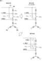
- FIG. 4 is a diagram for explaining an example of an unbalanced state of the motor.
- FIG. 5 is a diagram showing failure patterns of relays.
- FIG. 6 shows an example of a simulation of the phase currents, relay currents, and d- and q-axis currents when the motor is in an unbalanced state.
- FIG. 1 is a diagram illustrating an example of the configuration of a winding switching system according to the first embodiment.
- FIG. 2 is a block diagram illustrating an example of a hardware configuration of the control device.
- FIG. 3 is a circuit diagram showing an example of the configuration of the winding switching device according to the first embodiment.
- FIG. 4 is a
- FIG. 7 shows an example of a simulation of the phase currents, relay currents, and d- and q-axis currents when the motor is in an unbalanced state.
- FIG. 8 shows an example of a simulation of the phase currents, relay currents, and d- and q-axis currents when the motor is in an unbalanced state.
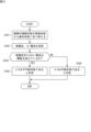
- FIG. 9 is a flowchart showing an example of a winding switching process performed by the control device according to the first embodiment.
- FIG. 10 is a circuit diagram showing an example of the configuration of a winding switching device according to the second embodiment.
- FIG. 11 is a flowchart showing an example of a winding switching process performed by the control device according to the second embodiment.
- FIG. 12 is a flowchart showing an example of a winding switching process performed by the control device according to the third embodiment.
- FIG. 13 is a circuit diagram showing an example of the configuration of a winding switching system according to the fourth embodiment.
- FIG. 14 is a flowchart showing an example of a winding switching process performed by the control device according to the fourth embodiment.
- FIG. 15 is a circuit diagram showing an example of the configuration of a winding switching system according to the fifth embodiment.
- FIG. 16 is a circuit diagram showing an example of the configuration of a winding switching system according to the sixth embodiment.
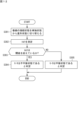
- FIG. 17 is a flowchart showing an example of a winding switching process performed by the control device according to the sixth embodiment.
- FIG. 18 is a circuit diagram showing an example of the configuration of a modified example of a winding switching device.
- abnormalities such as the relay that switches the windings becoming stuck can be detected based on the motor's equilibrium state.
- the winding switching system includes a winding switching unit that switches the connection state of multiple windings in an AC motor that includes multiple windings in a stator for each phase, a measurement unit that measures a physical quantity related to the rotation of the AC motor, and an abnormality detection unit that determines whether or not the current flowing through each phase of the AC motor is balanced based on the physical quantity measured by the measurement unit. This makes it possible to detect an abnormality in the winding switching unit that switches the windings based on the balanced state of the motor.
- the winding switching unit may switch the connection state of the multiple windings using multiple relays. This makes it possible to detect an abnormality in the winding switching unit that switches the windings using relays based on the balanced state of the motor.
- the abnormality detection unit may detect an abnormality occurring in the multiple relays by determining whether or not the currents flowing through each phase of the AC motor are balanced. This makes it possible to detect an abnormality in a winding switching unit that switches windings using relays by determining whether or not the currents flowing through each phase of the motor are balanced.
- the measurement unit may include a current sensor, which measures the current flowing through each of the phases, and the abnormality detection unit may determine that the current flowing through each of the phases is not balanced when the current measured by the current sensor exceeds a threshold value. In this way, when the current measured by the current sensor exceeds the threshold value, it is determined that an unbalanced state has occurred, and an abnormality in the winding switching unit can be detected based on this.
- the current sensor may measure the phase current flowing through the stator of each phase. In this way, when the phase current measured by the current sensor exceeds a threshold, it is determined that an unbalanced state exists, and an abnormality in the winding switching unit can be detected based on this.
- At least one of the plurality of relays may be a relay that is set on in a first connection state and set off in a second connection state, and the current sensor may measure the current (relay current) flowing through the relay that is set on.
- the relay current measured by the current sensor exceeds a threshold, it is determined that an unbalanced state has occurred, and an abnormality in the winding switching unit can be detected based on this.
- the AC motor may be a drive motor that drives the wheels of a vehicle
- the abnormality detection unit may change the threshold value based on the output required of the AC motor. In this way, the threshold value is changed based on the output required of the motor, which is determined by the accelerator opening, the required speed, the required torque, etc., so that the balanced state of the motor can be appropriately determined and an abnormality in the winding switching unit can be detected.
- the measurement unit may include a current sensor that measures the phase current flowing through the stator of each phase, and measure the d-axis current and the q-axis current flowing through the AC motor based on the phase current.
- the abnormality detection unit may compare a target d-axis current, which is a target value of the d-axis current, and a target q-axis current, which is a target value of the q-axis current, with a measured d-axis current, which is a measurement value of the d-axis current, and a measured q-axis current, which is a measurement value of the q-axis current, and determine that the currents flowing through each phase are not balanced when at least one of a first condition that the difference between the target d-axis current and the measured d-axis current is equal to or greater than a first threshold value and a second condition that the difference between the target q-axis current and the measured q-axis current is equal
- the AC motor is a drive motor that drives the wheels of a vehicle
- the abnormality detection unit may change at least one of the first threshold value and the second threshold value based on the output required of the AC motor.
- the threshold value is changed based on the output required of the motor, which is determined by the accelerator opening, the required speed, the required torque, etc., and the balanced state of the motor can be appropriately determined.
- the abnormality detection unit may determine that the currents flowing through the phases are not balanced when at least one of the period during which the first condition is satisfied and the period during which the second condition is satisfied exceeds a reference value. This makes it possible to eliminate erroneous determinations and properly determine the balanced state of the motor by determining that an unbalanced state exists when the difference is equal to or greater than a threshold value and continues for a predetermined period or longer, even in a situation where noise is suddenly introduced.
- the abnormality detection unit may change the reference value based on the rotation speed of the rotor of the AC motor. This makes it possible to appropriately determine the balanced state of the motor even when the rotor rotation speed decreases and the measured d-axis and q-axis currents fluctuate slowly.
- the measurement unit may include a voltage sensor that measures the voltages of the multiple windings. This makes it possible to determine the balanced state of the motor based on the voltages of the windings.
- the measurement unit may include a sensor that measures the output torque or rotation speed of the AC motor. This makes it possible to determine the equilibrium state of the motor based on the torque or rotation speed of the motor.
- the winding switching system may further include a return unit that returns the winding switching unit to the connection state before switching when the abnormality detection unit determines that the currents flowing through the phases of the AC motor are not balanced in response to the winding switching unit switching the connection state. In this way, when an abnormality is detected in the winding switching unit that switches the windings, the winding switching unit is returned to the connection state before switching, and the motor can continue to operate.
- the winding switching system may further include a notification unit that notifies a user of the occurrence of an abnormality when the abnormality detection unit determines that the currents flowing through the phases of the AC motor are not balanced. This allows the user of the motor to know that the motor is unbalanced.
- the winding switching system includes a winding switching unit that switches the connection state of a plurality of windings of an AC motor capable of switching the connection state of the plurality of windings included in the stator of each phase, a measurement unit that measures a physical quantity related to the rotation of the AC motor, and an equilibrium determination unit that determines whether or not the current flowing through each phase of the AC motor is balanced based on the physical quantity measured by the measurement unit, and a return unit that causes the winding switching unit to switch the connection state from the second state to the first connection state when the balance determination unit's determination changes from a determination that the current flowing through each phase is balanced to a determination that the current flowing through each phase is not balanced in response to the connection state being switched from the first connection state to the second connection state.
- the control device includes a winding switching unit that switches the connection state of multiple windings of an AC motor that includes a stator for each phase; a measurement unit that includes a sensor that measures a physical quantity related to the rotation of the AC motor; and an abnormality detection unit that determines whether or not the current flowing through each phase of the AC motor is balanced based on the physical quantity measured by the measurement unit.
- the control method for the winding switching device includes a winding switching step of switching the connection state of a plurality of windings of an AC motor including a stator of each phase, a measurement step of measuring a physical quantity related to the rotation of the AC motor, and an anomaly detection step of determining whether or not the current flowing through each phase of the AC motor is balanced based on the physical quantity measured in the measurement step. This makes it possible to detect an anomaly in the winding switching unit that switches the windings based on the balanced state of the motor.
- the computer program according to this embodiment is a computer program used by a control device that controls a winding switching device, and causes a computer to execute a winding switching step of switching the connection state of multiple windings of an AC motor capable of switching the connection state of the multiple windings included in the stator of each phase, a measurement step of measuring a physical quantity related to the rotation of the AC motor, and an abnormality detection step of determining whether or not the current flowing through each phase of the AC motor is balanced based on the physical quantity measured in the measurement step. This makes it possible to detect an abnormality in the winding switching unit that switches the windings based on the balanced state of the motor.
- FIG. 1 is a diagram illustrating an example of the configuration of a winding switching system according to the first embodiment.
- the winding switching system 10 is mounted on a vehicle (hereinafter referred to as an "electric vehicle") that is propelled by a motor, such as an electric vehicle or a plug-in hybrid vehicle.
- the winding switching system 10 includes a motor 20, a power converter 30, a battery 40, a control device 50, and a winding switching device 100.
- Motor 20 is a driving motor that generates the propulsion force for the electric vehicle.
- motor 20 is connected to wheels 60 and is a drive motor that drives wheels 60.
- Motor 20 is driven by three-phase AC power.
- Motor 20 is a non-commutator type AC motor that does not have a commutator and drives a stator to generate a rotating magnetic field, which then rotates the rotor.
- Non-commutator type AC motors include, for example, synchronous motors, reluctance motors, and induction motors.
- the battery 40 is a battery that supplies power to drive the motor 20.
- the battery 40 is a secondary battery, for example a lithium ion battery.
- the power converter 30 is an inverter that converts DC power supplied from the battery 40 into three-phase AC power.
- the power converter 30 may also have the function of converting the three-phase AC power output when the motor 20 functions as a generator into DC power and charging the battery 40.
- the power converter 30 includes legs for the U, V, and W phases.
- the U-phase leg includes switches 31u and 32u
- the V-phase leg includes switches 31v and 32v
- the W-phase leg includes switches 31w and 32w.
- the switches 31u, 32u, 31v, 32v, 31w, and 32w perform switching to convert DC power into three-phase AC power.
- the switches 31u, 32u, 31v, 32v, 31w, and 32w are, for example, IGBTs (Insulated Gate Bipolar Transistors) or MOSFETs (Metal Oxide Semiconductor Field-Effect Transistors).
- Power line 35u corresponding to U phase extends from the U phase leg
- power line 35v corresponding to V phase extends from the V phase leg
- power line 35w corresponding to W phase extends from the W phase leg.
- current sensor 33u is provided on power line 35u
- current sensor 33v is provided on power line 35v
- current sensor 33w is provided on power line 35w.
- Current sensor 33u detects the current value of current Iu of U phase.
- Current sensor 33v detects the current value of current Iv of V phase.
- Current sensor 33w detects the current value of current Iw of W phase.
- Current sensors 33u, 33v, 33w can detect the current values of currents Iu, Iv, Iw flowing through power lines 35u, 35v, 35w, including DC and AC components.
- the current sensors 33u, 33v, and 33w are, for example, DC current sensors using Hall sensors or shunt resistors.
- the winding switching device 100 is disposed between the motor 20 and the power converter 30.
- the power converter 30 and the winding switching device 100 are connected by power lines 35u, 35v, and 35w, and the winding switching device 100 and the motor 20 are connected by a plurality of power lines 25.
- the winding switching device 100 switches the connection state of the multiple windings of the motor 20. The configuration of the winding switching device 100 will be described later.
- the three-phase AC currents Iu, Iv, and Iw output from the power converter 30 are supplied to the motor 20 via the winding switching device 100.
- the measuring device 26 measures physical quantities related to the rotation of the motor 20.
- Examples of physical quantities related to the rotation of the motor include, but are not limited to, the current flowing through each winding of the motor 20, the voltage of each winding, and the torque of the output shaft of the motor 20.
- the measuring device 26 is provided at a location corresponding to the measurement target.
- the measuring device 26 is provided on the power lines 212u, 221u, 212v, 221v, 212w, and 221w connecting the winding switching device 100 and the motor 20.
- the measuring device 26 is provided on the output shaft of the motor 20.
- the current is measured by a current sensor.
- the current sensor is, for example, a DC current sensor using a Hall sensor.
- the voltage is measured by a voltage sensor.
- the voltage sensor is, for example, an AD converter.
- the first terminal of the winding and the reference voltage point (the body of the vehicle) are connected to the first terminal and the second terminal of the input terminal of the AD converter, respectively. If the processor 501 described below has an AD converter built in, the first and second terminals of the winding may be connected to the first and second input terminals of the AD converter of the processor 501.
- the torque is measured by a torque sensor, such as a strain gauge.
- the control device 50 controls the motor 20. Specifically, the control device 50 controls the motor 20 by controlling the power converter 30 and the winding switching device 100. Signal lines extend from the control device 50 to each of the switches 31u, 32u, 31v, 32v, 31w, and 32w, and the control device 50 controls the on/off timing of the switches 31u, 32u, 31v, 32v, 31w, and 32w. A signal line extends from the control device 50 to the winding switching device 100, and the control device 50 outputs a switching command signal to the winding switching device 100 to command the switching of the winding connection state.
- the control device 50 may be configured to vector control the motor 20.
- Vector control is a method of decomposing the current flowing through the U-phase, V-phase, and W-phase of the AC motor stator into a current component that generates magnetic flux and a current component that generates torque, and controlling each current component independently. This makes it possible to control the direction and magnitude of the magnetic flux of the rotating magnetic field of the motor as a vector quantity.
- the current component that generates magnetic flux may be called the d-axis current, and the current component that generates torque may be called the q-axis current.
- the current flowing through the U-phase, V-phase, and W-phase of the motor stator may be measured, and the d-axis current and q-axis current may be calculated based on the measured current.
- the control device 50 compares the target d-axis current, which is the target value of the d-axis current, and the target q-axis current, which is the target value of the q-axis current, with the measured d-axis current, which is the measured value of the d-axis current, and the measured q-axis current, which is the measured value of the q-axis current, and controls the power converter 30 so that the measured d-axis current and the measured q-axis current become the target d-axis current and the target q-axis current, respectively.
- the target d-axis current and target q-axis current are determined, for example, based on the output (rotational speed, torque) required of the motor 20.
- the control device 50 is connected to a sensor 71 that detects the amount of depression of the brake pedal 70, and receives a detection signal output from the sensor 71.
- the control device 50 is connected to a sensor 81 that detects the amount of depression of the accelerator pedal 80, and receives a detection signal output from the sensor 81.
- a rotation sensor 201 that detects the rotation speed of the motor 20 and a torque sensor 202 that detects the output torque of the motor 20 are attached to the output shaft of the motor 20.
- the rotation sensor 201 and the torque sensor 202 are connected to the control device 50.
- the control device 50 receives the detection signal output from the rotation sensor 201 and receives the detection signal output from the torque sensor 202.
- the control device 50 is connected to a gear shift indicator 90.
- the gear shift indicator 90 is an input device that allows the driver to input gear shift instructions.
- the gear shift indicator 90 is, for example, a shift lever.
- the gear shift indicator 90 is a switch that allows the driver to instruct shifting up or down.
- the gear shift indicator 90 outputs a gear shift instruction signal in response to the driver's operation.
- the control device 50 receives the gear shift instruction signal output from the gear shift indicator 90.
- FIG. 2 is a block diagram showing an example of the hardware configuration of the control device.
- the control device 50 includes a processor 501, a non-volatile memory 502, a volatile memory 503, and an interface (I/F) 504.
- I/F interface
- the volatile memory 503 is, for example, a semiconductor memory such as SRAM (Static Random Access Memory) or DRAM (Dynamic Random Access Memory).
- the non-volatile memory 502 is, for example, a flash memory, a hard disk, or a ROM (Read Only Memory).
- the non-volatile memory 502 stores a motor control program 510, which is a computer program, and data used to execute the motor control program 510. Each function of the control device 50 is achieved by the motor control program 510 being executed by the processor 501.
- the motor control program 510 can be stored in a recording medium such as a flash memory, a ROM, or a CD-ROM.
- the processor 501 controls the power converter 30 and the winding switching device 100 using the motor control program 510.
- the processor 501 is, for example, a CPU (Central Processing Unit). However, the processor 501 is not limited to a CPU.
- the processor 501 may be a GPU (Graphics Processing Unit).
- the processor 501 is, for example, a multi-core processor.
- the processor 501 may be a single-core processor.
- the processor 501 may be, for example, an ASIC (Application Specific Integrated Circuit), or a programmable logic device such as a gate array or an FPGA (Field Programmable Gate Array). In this case, the ASIC or the programmable logic device is configured to be capable of executing the same processing as the motor control program 510.
- ASIC Application Specific Integrated Circuit
- FPGA Field Programmable Gate Array
- the I/F 504 is connected to the rotation sensor 201, the torque sensor 202, the sensor 71, the sensor 81, and the gear shift indicator 90.
- the I/F 504 is, for example, an input/output interface or a communication interface.
- the I/F 504 receives a detection signal of the rotation speed of the motor 20 output from the rotation sensor 201.
- the I/F 504 receives a detection signal of the output torque of the motor 20 output from the torque sensor 202.
- the I/F 504 receives a detection signal of the brake pedal depression amount output from the sensor 71.
- the I/F 504 receives a detection signal of the accelerator pedal depression amount output from the sensor 81.
- the I/F 504 receives a gear shift indicator signal output from the gear shift indicator 90.
- FIG. 3 is a circuit diagram showing an example of the configuration of the winding switching device according to the first embodiment.
- the motor 20 includes a plurality of windings 21u, 22u, 21v, 22v, 21w, and 22w.
- the windings 21u and 22u correspond to the U phase
- the windings 21v and 22v correspond to the V phase
- the windings 21w and 22w correspond to the W phase.
- the number of windings for each phase is not limited to two, and may be three or more.
- the windings 22u, 22v, and 22w are connected at a neutral point 23.
- the winding switching device 100 switches the connection state of the windings 21u, 22u, 21v, 22v, 21w, and 22w for each phase between a two windings connected in series state and a one winding connected state.
- the winding switching device 100 includes control circuits 103u, 103v, and 103w, and switching circuits 104u, 104v, and 104w.
- the two windings connected in series state may be referred to as the series state
- the one winding connected state may be referred to as the single state.
- the switching circuits 104u, 104v, and 104w switch the connection state of the windings 21u, 22u, 21v, 22v, 21w, and 22w between a series state and an independent state under control of the control device 50.
- the series state is an example of a first connection state
- the independent state is an example of a second connection state.
- the power line 35u is connected to a first terminal of the winding 21u.
- the power line 212u extends from a second terminal of the winding 21u.
- the power line 221u extends from a first terminal of the winding 22u.
- the switching circuit 104u includes a relay 111u and a relay 112u.
- the relay 111u and the relay 112u are, for example, mechanical (electromagnetic) relays, but are not limited to this and may be semiconductor relays.
- the relay is divided into an input side and an output side.
- the output side of the relay includes a switch that controls the current to be on or off, and the switch is set to on/off by inputting a predetermined control signal to the input side.
- the input side is composed of an electromagnetic coil.
- the output side is composed of a mechanical switch including a movable segment and a fixed segment. The movable segment and the fixed segment each have a contact.
- the movable segment is attracted in one direction by an elastic body such as a spring, and is attracted in the other direction by the electromagnetic coil.
- the contact is configured to be in a conductive state when the electromagnetic coil attracts the movable segment in the other direction.
- the input side is composed of a light-emitting diode
- the output side is composed of a light-receiving element, a MOSFET, and an IGBT.
- the power line 35u is drawn into the winding switching device 100. Inside the winding switching device 100, the power line 35u branches at a midpoint and is connected to a first terminal of a relay 111u. The second terminal of the relay 111u is connected to a first terminal of a relay 112u.
- the power lines 212u, 221u, and 222u extend from the motor 20 and are drawn into the winding switching device 100.
- the power line 221u extending from the winding 22u is connected to the connection point between the second terminal of the relay 111u and the first terminal of the relay 112u.
- the power line 212u extending from the winding 21u is connected to the second terminal of the relay 112u.
- winding 21u and winding 22u are in a series state.
- winding 21u is in an isolated state.
- a signal line extending from the control circuit 103u is connected to each of the input sides (electromagnetic coil side) of the relay 112u and the relay 111u.
- the control circuit 103u is connected to a signal line extending from the control device 50.
- the signal line communicates instructions indicating which connection state the windings should be in. This signal is sometimes called a switching instruction. For example, a LOW level of the signal line indicates a series state, and a HIGH level indicates a single state. Alternatively, data communication may be performed via the signal line to send and receive information indicating which relay to set on or off.
- the control circuit 103u controls the on/off of the relays 112u and 111u by applying control signals to the input sides of the relays 112u and 111u individually. Specifically, when the control circuit 103u receives an instruction from the control device 50 to switch the connection state of the windings 21u, 22u from a series state to an independent state, the control circuit 103u sets the relay 111u to an on state and the relay 112u to an off state. When the control circuit 103u receives an instruction from the control device 50 to switch the connection state of the windings 21u, 22u from a series state to an independent state, the control circuit 103u sets the relay 111u to an off state and the relay 112u to an on state.
- the control circuit 103u is, for example, configured with multiple logic circuits (AND circuits, NOT circuits, latch circuits, etc.). In another example, the control circuit 103u is configured with a processor. For example, the control circuit 103u is configured with a one-chip microcomputer. The control circuit 103u may also be configured with a programmable logic device such as an ASIC or FPGA.
- the measuring device 26 is provided, for example, on the power line connecting the winding switching device 100 and the motor 20.
- the measuring device 26 includes, for example, a phase current sensor and a relay current sensor.
- the phase current sensor 261u is provided on the power line 221u, and the relay current sensor 262u is provided on the power line 212u.
- the phase current sensor 261u measures the current flowing through the U phase when the windings 21u and 22u are in series and alone.
- the current measured by the phase current sensor may be referred to as the phase current.
- the phase current sensor 261u sends a signal or information indicating the value of the measured current to the control device 50.
- the relay current sensor 262u measures the current flowing through the power line 212u connected to the second terminal of the relay 112u.
- the relay current sensor 262u measures the current of the power line 212u that the relay 112u, which is set to off, is attempting to cut off.
- the current measured by the relay current sensor may be referred to as the relay current.
- the relay current sensor 262u sends a signal or information indicating the value of the measured current to the control device 50.
- a phase current sensor 261v is provided on the power line 221v
- a relay current sensor 262v is provided on the power line 212v
- a phase current sensor 261w is provided on the power line 221w
- a relay current sensor 262w is provided on the power line 212w. Note that, although an example has been described in which the measuring device 26 is provided on the power line connecting the winding switching device 100 and the motor 20, the measuring device 26 may be provided in the winding switching device 100 or in the motor 20.
- the control device 50 has the functions of a winding switching unit 511, a measurement unit 512, and an abnormality detection unit 513.
- the processor 501 executes the motor control program 510 to realize each of the functions of the winding switching unit 511, the measurement unit 512, and the abnormality detection unit 513.
- the winding switching unit switches the connection states of the windings of an AC motor including a stator for each phase.
- the winding switching unit also switches the connection states of the windings by a plurality of relays. At least one of the plurality of relays is set to on in a first connection state and set to off in a second connection state.
- the winding switching unit 511 switches the connection state of the windings 21u, 22u, 21v, 22v, 21w, and 22w for each phase between a state in which two windings are connected in series and a state in which one winding is connected.
- the winding switching device 100 includes control circuits 103u, 103v, and 103w and switching circuits 104u, 104v, and 104w.
- the winding switching unit 511 causes the switching circuits 104u, 104v, and 104w to switch the connection state of the windings 21u, 22u, 21v, 22v, 21w, and 22w between a series state and a single state.
- the winding switching unit 511 transmits a switching instruction to the control circuits 103u, 103v, and 103w. For example, a low level of the switching command indicates a series state, and a high level indicates a single state.
- the measurement unit 512 measures a physical quantity related to the rotation of the AC motor.
- An example of the physical quantity related to the rotation of the motor is the current flowing through each phase of the motor 20.
- the measurement unit 512 includes a current sensor, and the current sensor measures the current flowing through each phase.
- the current sensor measures the phase current flowing through the stator of each phase. Specifically, in the U phase, the phase current sensor 261u measures the current flowing through the power line 221u. 512 measures the phase current flowing through the U-phase stator.
- the current sensor also measures the current flowing through the relay switch. Specifically, in the U phase, the relay current sensor 262u measures the current flowing through the power line 212u, and the measurement unit 512 measures the relay current of the U phase.
- phase current sensor 261u and the relay current sensor 262u send a signal or information indicating the measured current value to the control device 50.
- the measurement unit 512 of the control device 50 receives the signal or information indicating the measured current value and measures a physical quantity related to the rotation of the AC motor. The same is true for the V phase and the W phase.
- the abnormality detection unit 513 judges whether or not the currents flowing through each phase of the AC motor are balanced based on the physical quantities measured by the measurement unit 512.
- the currents flowing through each phase of the motor 20 are not balanced means that the balance of the currents flowing through the U phase, V phase, and W phase is different from one another.
- the state in which the currents flowing through each phase of the motor 20 are not balanced is sometimes referred to as an unbalanced state, and the state in which the currents flowing through each phase of the motor 20 are balanced is sometimes referred to as a balanced state.
- Motor Unbalance 4 is a diagram for explaining an example of an unbalanced state of the motor 20.
- the U-phase windings 21u, 22u and relays 111u, 112u necessary for the explanation are shown.
- the state before the winding switching device 100 switches the winding connection state is assumed to be an isolated state.
- the relay 111u is set to on, and the relay 112u is set to off (FIG. 4. Isolated state).
- the relay 111u is set to off, and if the relays are normal, the relay 112u is set to on (FIG. 4. Series state).
- Figure 5 shows types of relay failures. Possible relay failure patterns include when the output contacts become stuck and remain connected (fixed on), and when the relay's electromagnetic coil becomes disconnected and the output contacts remain open (fixed off). In Figure 5, off is represented by “0" and on by "1". Figure 5 shows when the winding connection state is switched from an isolated state to a series state, and when the winding connection state is switched from a series state to an isolated state. Figure 5 also shows the state of the relay current and the states of the d- and q-axis currents.
- relay 111u is fixed on, relays 111u and 112u are both set on, and winding 21u is short-circuited; (2) relay 112u is fixed off, relays 111u and 112u are both set off, and no current flows through U-phase windings 21u and 22u; or (3) relay 111u is fixed on, relay 112u is fixed off, and although the V-phase and W-phase windings have switched to a series state, U-phase remains in an isolated state.
- relay 112u is fixed on, relays 111u and 112u are both set on, and winding 21u is short-circuited; (2) relay 111u is fixed off, relays 111u and 112u are both set off, and no current flows through U-phase windings 21u and 22u; or (3) relay 111u is fixed off, relay 112u is fixed on, and although the V-phase and W-phase windings have been switched to an independent state, the U-phase remains in a series state.
- Figures 6, 7, and 8 are examples of simulations of the phase currents, relay currents, and d- and q-axis currents when one of the relays that change the winding connection state fails and the motor 20 becomes unbalanced.
- the winding connection state is switched at 0.015 s on the time axis.
- each current shows a normal state, but after 0.015 s on the time axis, one of the currents becomes abnormal.
- the abnormality detection unit 513 detects this abnormal value and determines that the motor 20 is unbalanced.
- phase current or relay current shows a case where the U-phase relays 112u and 111u are both turned on when the connection state changes from the single state to the series state.
- both ends of the winding 21u are short-circuited and the rotor of the motor 20 is rotating, so the winding 21u functions as a generator and a large current circulates through the winding 21u.
- This large current is larger than the relay current that flows under normal conditions.
- the windings 21u and 22u are connected in series, so the relay current and the phase current flow approximately equal to each other.
- Figure 7 shows the case where the U-phase relays 112u and 111u are both turned off when the connection state changes from an isolated state to a series state. In this case, no phase current or relay current flows through the U-phase. On the other hand, a current larger than the current that flows normally flows through the V-phase and W-phase.
- the abnormality detection unit 513 determines whether the currents flowing through each phase of the motor 20 are in a balanced state based on the signal indicating this large current measured by the measurement unit 512. Specifically, the abnormality detection unit 513 determines that the currents flowing through each phase are not in balance when the currents measured by the current sensors exceed a threshold value.
- the abnormality detection unit 513 may determine that motor 20 is in an unbalanced state based on this current.
- the abnormality detection unit 513 may also change the threshold value based on the output required of the motor 20. This is because the current that flows normally increases according to the required motor output. This allows the balanced state of the motor 20 to be appropriately determined. If the motor 20 is a drive motor that drives the wheels of the vehicle, the required output is determined based on, for example, the accelerator opening, the speed required by the vehicle, and the torque required by the vehicle.
- the anomaly detection unit 513 determines whether the currents flowing through each phase are balanced.
- [In the case of d- and q-axis currents] 8 shows a case where the U-phase relay 111u is turned on and the relay 112u is turned off when the connection state changes from the isolated state to the series state. In this state, the V-phase and W-phase are in series, but only the U-phase is in an isolated state. In this case, the phase currents of the U-phase, V-phase, and W-phase flow substantially the same as in a normal state. For this reason, it is difficult to determine whether the motor 20 is in a balanced state based on the phase currents alone. On the other hand, currents flowing through the d- and q-axis are clearly different from those flowing in a normal state. As a result, an unbalanced state can be determined based on the d- and q-axis currents calculated from the phase currents flowing through the U-phase, V-phase, and W-phase.
- the abnormality detection unit 513 compares the target d-axis current, which is the target value of the d-axis current, and the target q-axis current, which is the target value of the q-axis current, with the measured d-axis current, which is the measured value of the d-axis current, and the measured q-axis current, which is the measured value of the q-axis current, and determines that the currents flowing through each phase are not balanced when at least one of the following conditions is met: a first condition that the difference between the target d-axis current and the measured d-axis current is equal to or greater than a first threshold value, and a second condition that the difference between the target q-axis current and the measured q-axis current is equal to or greater than a second threshold value.
- the first threshold value and the second threshold value may be the same value or may be different values.
- the abnormality detection unit 513 determines that the motor 20 is in an unbalanced state, thereby making it possible to more appropriately determine the balanced state of the motor 20.
- the reference value may also be changed based on the rotation speed of the rotor of the motor 20. Since the d- and q-axis currents fluctuate in response to the rotation of the rotor, the d- and q-axis currents fluctuate slowly when the rotation speed of the rotor of the motor 20 decreases. For this reason, it is preferable to lengthen the specified period as the rotation speed of the rotor decreases. This allows the balanced state of the motor 20 to be appropriately determined.
- the first and second thresholds may be changed, for example, according to the output required of the motor 20. This is because the current that flows normally increases according to the required motor output. This allows the balanced state of the motor 20 to be appropriately determined. If the motor 20 is a drive motor that drives the wheels of a vehicle, the required output is determined based on, for example, the accelerator opening, the speed required by the vehicle, and the torque required by the vehicle.
- the anomaly detection unit 513 determines whether the currents flowing through each phase are balanced.
- the control device 50 executes a winding switching process by the processor 501 executing the motor control program 510.
- FIG. 9 is a flowchart showing an example of a winding switching process performed by the control device according to the first embodiment.
- the winding switching unit 511 switches the connection state of the multiple windings of an AC motor including multiple windings in a stator of each phase (step S101). For example, the winding switching unit 511 switches the connection state of the windings from an independent state to a series state. Specifically, the winding switching unit 511 transmits a switching instruction to the control circuits 103u, 103v, and 103w to switch the connection state of the windings 21u, 22u, 21v, 22v, 21w, and 22w from an independent state to a series state.
- the control circuit 103u that has received the switching instruction to switch the connection state from an independent state to a series state sets the relay 112u on and the relay 111u off. Similarly, the control circuit 103v sets the relay 112v on and the relay 111v off.
- the control circuit 103w sets the relay 112w on and the relay 111w off. Then, the process proceeds to step S102.
- relay 111u is stuck, so relays 111u and 112u are set to on. This causes both ends of winding 21u to be shorted, causing a large relay current to flow through winding 21u as shown in Figure 6.
- the measurement unit 512 measures a physical quantity related to the rotation of the AC motor (step S102). Specifically, the phase current sensor 261u measures the phase current and transmits a signal indicating the value of the phase current to the control device 50.
- the relay current sensor 262u measures the relay current and transmits a signal indicating the value of the relay current to the control device 50. In this example, the relay current sensor 262u measures a large current circulating through the winding 21u and transmits a signal indicating the value of this current.
- the measurement unit 512 measures the phase current and relay current, which are physical quantities related to the rotation of the motor 20. Then, the process proceeds to step S103.
- Step S103 the abnormality detection unit 513 judges whether or not the currents flowing through each phase of the motor 20 are balanced based on the physical quantities measured by the measurement unit 512. Specifically, the abnormality detection unit 513 compares the phase currents or relay currents measured by the measurement unit 512 with a threshold value (step S103). If the threshold value is exceeded (YES in step S103), the process proceeds to step S104. On the other hand, if the threshold value is not exceeded (NO in step S103), the process proceeds to step S105.
- the control device 50 receives a signal indicating a large current value circulating through the winding 21u.
- the abnormality detection unit 513 of the control device 50 compares the received relay current value with a threshold value. Since the relay current value indicates a large current value, it exceeds the threshold value, and the abnormality detection unit 513 determines that the motor 20 is in an unbalanced state.
- Step S104 If the phase current or relay current exceeds the threshold value, the abnormality detection unit 513 determines that the currents flowing through the phases of the motor 20 are not balanced (step S104), and the winding switching process is terminated.
- Step S105 On the other hand, if the phase current and the relay current do not exceed the threshold value, the abnormality detection unit 513 determines that the currents flowing through the phases of the motor 20 are balanced (step S105), and ends the winding switching process.
- Step S101 Next, it is assumed that the winding switching unit 511 switches the connection state of the windings from a series state to an independent state (step S101).
- the relay 112u is set to OFF, and the relay 111u is set to ON. If the relays 112u and 111u are normal, a predetermined current flows through the U-phase winding 22u. However, since the relay 111u is fixed to OFF, the U-phase relays 112u and 111u are both set to OFF, and no current flows through the U-phase winding. On the other hand, as shown in FIG. 7, a large current flows through the V-phase and W-phase windings 22v and 22w.
- the measurement unit 512 measures the phase currents of the U-phase, V-phase, and W-phase of the motor 20 using the phase current sensors 261u, 261v, and 261w. Specifically, the phase current sensor 261u transmits a signal indicating that the current value is zero to the control device 50. The phase current sensors 261v and 261w transmit signals indicating large current values of the V-phase and W-phase to the control device 50. When the control device 50 receives such signals, the measurement unit 512 measures the phase currents. Then, the process proceeds to step S103.
- the abnormality detection unit 513 judges whether the currents flowing through each phase of the motor 20 are balanced based on the physical quantities measured by the measurement unit 512.
- the value of the phase current of the V phase indicates a large current and therefore exceeds the threshold (YES in step S103), and the abnormality detection unit 513 judges that the motor 20 is in an unbalanced state (step S104).
- the abnormality detection unit 513 may make the judgment based on the phase current of the W phase.
- the abnormality detection unit 513 may make the judgment based on the phase current of the U phase.
- step S105 the abnormality detection unit 513 judges that the motor 20 is in a balanced state.
- Step S101 the winding switching unit 511 switches the connection state of the windings from the single state to the series state (step S101).
- the control circuit 103u sets the relay 112u on and attempts to set the relay 111u off.
- the connection state of the U-phase winding does not switch to the series state and remains in the single state.
- the connection states of the V-phase and W-phase windings are switched to the series state. In this connection state, as shown in FIG. 8, the phase current or relay current does not become significantly large. Meanwhile, when attention is paid to the d-axis and q-axis currents, they fluctuate significantly. Then, the process proceeds to step S102.
- Step S102 the measurement unit 512 measures the phase currents of the U-phase, V-phase, and W-phase of the motor 20 using the phase current sensors 261u, 261v, and 261w, and outputs a signal indicating the measured phase currents.
- the control device 50 receives this signal, the measurement unit 512 measures the phase currents (step S102). Then, the process proceeds to step S103.
- the abnormality detection unit 513 compares the target d-axis current, which is the target value of the d-axis current, and the target q-axis current, which is the target value of the q-axis current, with the measured d-axis current, which is the measured value of the d-axis current, and the measured q-axis current, which is the measured value of the q-axis current, and determines that the currents flowing through each phase are not balanced (step S104) when at least one of a first condition that the difference between the target d-axis current and the measured d-axis current is equal to or greater than a first threshold value and a second condition that the difference between the target q-axis current and the measured q-axis current is equal to or greater than a second threshold value is satisfied (YES in step S103).On the other hand, when the threshold values are not exceeded (NO in step S103), the abnormality detection unit 513 determines that the motor 20
- the abnormality detection unit 513 determines that the motor 20 is in an unbalanced state (step S104). If neither the first condition nor the second condition is satisfied (NO in step S103), the abnormality detection unit 513 determines that the motor 20 is in a balanced state (step S105).
- the abnormality detection unit 513 may also determine that the currents flowing through the phases are not balanced if at least one of the period during which the first condition is satisfied and the period during which the second condition is satisfied exceeds a reference value.
- the abnormality detection unit 513 judges whether the period during which the difference between the target d-axis current and the measured d-axis current is equal to or greater than a first threshold is longer than a predetermined period. Second, the abnormality detection unit 513 judges whether the period during which the difference between the target q-axis current and the measured q-axis current is equal to or greater than a second threshold is longer than a predetermined period. Then, when at least one of the first and second judgments is satisfied (YES in step S103), the abnormality detection unit 513 judges that the motor 20 is in an unbalanced state (step S104). On the other hand, when neither the first nor the second judgment is satisfied (NO in step S103), the abnormality detection unit 513 judges that the motor 20 is in a balanced state (step S105).
- the measurement unit of the winding switching system according to the second embodiment includes a voltage sensor, which measures the voltages of the multiple windings.
- the second embodiment differs from the first embodiment in the configuration of the measurement device 26, but the other configurations are the same. Descriptions of the same configurations as in the first embodiment will be omitted, and only the different parts will be described, with the same reference numerals used for the same configurations.
- FIG. 10 is a circuit diagram showing an example of the configuration of a winding switching device according to the second embodiment. Although only the U phase is shown in detail, the V phase and the W phase are similar.
- a voltage Vpu between a power line 212u connecting the winding 21u and the relay 112u and a reference voltage point and a voltage Vru between a power line 221u connecting the relay 112u and the winding 22u and a reference voltage point are measured.
- the reference voltage point is, for example, the body of a vehicle.
- the measurement points are the same as those in the first embodiment, but are not limited to this.
- the voltage is measured by a voltage sensor.
- the voltage sensor is, for example, an AD converter.
- a first terminal of the input of the AD converter is connected to the power line 212u, and a second terminal is connected to a reference voltage point.
- the voltage sensor is not limited to an AD converter, and may be a photocoupler, etc.
- the control device 50 executes a winding switching process by the processor 501 executing the motor control program 510.
- FIG. 11 is a flowchart showing an example of a winding switching process performed by the control device according to the second embodiment.
- Step S201 First, the winding switching unit 511 switches the connection state of the windings from an independent state to a serial state. Specifically, the control device 50 transmits a switching instruction to the control circuits 103u, 103v, and 103w to switch the connection state of the windings 21u, 22u, 21v, 22v, 21w, and 22w from an independent state to a serial state (step S201).
- the control circuit 103u which has received the switching instruction to switch the connection state from an independent state to a serial state, sets the relay 112u to on and the relay 111u to off.
- the control circuit 103v sets the relay 112v to on and the relay 113v to off.
- the control circuit 103w sets the relay 112w to on and the relay 113w to off. Then, the process proceeds to step S202.
- relay 112u is fixed off, so relays 112u and 111u are set off. Under normal circumstances, relay 112u is set on and windings 21u and 22u are connected in series. Vpu or Vru, which is the voltage at the midpoint of windings 21u and 22u connected in series, is approximately half the voltage of power line 35u and neutral point 23. However, because relay 112u is fixed off, Vpu or Vru becomes a voltage that is completely different from the normal situation. For example, if the rotor is a permanent magnet, a voltage is generated by the rotating permanent magnet in windings 21u and 22u, and this voltage is completely different from the normal situation.
- relay 112u is set to on, so the voltage between the first and second terminals on the output side (contact side) of relay 112u is zero. However, because relay 112u is fixed to off, a voltage greater than zero is generated between the first and second terminals on the output side (contact side) of relay 112u.
- the measurement unit 512 measures a physical quantity related to the rotation of the motor 20 (step S202).
- the measurement unit 512 measures the physical quantity related to the rotation using a voltage sensor that measures the voltages of multiple windings.
- the voltage sensor measures Vpu and Vpr, and transmits a signal indicating Vpu and Vpr to the control device 50.
- the control device 50 receives this signal, the measurement unit 512 measures Vpu and Vpr. Then, the process proceeds to step S203.
- the abnormality detection unit 513 determines the balanced state of the motor 20 (steps S203 to S205).
- the abnormality detection unit 513 compares Vpu and Vpr measured by the measurement unit 512 with a threshold value, and if the threshold value is exceeded (YES in step S203), it determines that the motor 20 is unbalanced (step S204). Then, the winding switching process ends.
- step S203 If the threshold value is not exceeded (NO in step S203), it is determined that the motor 20 is in a balanced state (step S205). Then, the winding switching process ends.
- Vpu and Vpr are completely different values from normal and therefore exceed the threshold value, and the abnormality detection unit 513 determines that the motor 20 is unbalanced.
- the determination may also be made based on the difference between Vpu and Vru.
- the voltage across both ends of the relay 112u is measured.
- the relay 112u is set on, the voltage across both ends of the relay 112u is zero.
- the relay 112u is set off, the voltage across both ends of the relay 112u is greater than zero.
- the motor's balanced state can be determined using the voltage sensor.
- the measurement unit of the winding switching system according to the third embodiment measures the torque or rotation speed of the output shaft of an AC motor using a sensor that measures the torque or rotation speed.
- the third embodiment differs from the first embodiment in the configuration of the measurement device 26, but the other configurations are the same. Descriptions of configurations similar to those of the first embodiment will be omitted, and only different parts will be described, with the same reference numerals used for the same configurations. The case of a torque sensor will be described below.
- the control device 50 executes a winding switching process by the processor 501 executing the motor control program 510.
- FIG. 12 is a flowchart showing an example of a winding switching process performed by the control device according to the third embodiment.
- Step S301 the winding switching unit 511 switches the connection state of the windings from an independent state to a serial state.
- the control device 50 transmits a switching instruction to the control circuits 103u, 103v, and 103w to switch the connection state of the windings 21u, 22u, 21v, 22v, 21w, and 22w from an independent state to a serial state (step S301).
- the control circuit 103u that receives the switching instruction to switch the connection state from an independent state to a serial state sets the relay 112u to on and the relay 111u to off.
- the control circuit 103v sets the relay 112v to on and the relay 113v to off.
- the control circuit 103w sets the relay 112w to on and the relay 113w to off. Then, the process proceeds to step S302.
- relay 112u is fixed to off, so relays 112u and 111u are set to off.
- no current flows through U-phase windings 21u and 22u.
- V-phase and W-phase are in series and a large current flows through them, but they are excited.
- the rotating magnetic field generated by the U-phase, V-phase, and W-phase windings is distorted, and the torque generated by the rotor, which obtains torque from the rotating magnetic field, fluctuates greatly.
- the torque pulsates greatly in synchronization with the rotation of the rotor.
- the measurement unit 512 measures the state of the motor 20 (step S302). Specifically, the torque of the output shaft of the motor 20 is measured by the torque sensor 202, and a signal indicating the torque is transmitted to the control device 50. In this example, a signal indicating, for example, a large pulsating torque is transmitted. When the control device 50 receives this signal, the measurement unit 512 measures the torque. Then, the process proceeds to step S303.
- the abnormality detection unit 513 determines the balanced state of the motor 20 .
- the measurement unit 512 receives a signal indicating the torque of the output shaft of the motor 20 output by the torque sensor.
- the abnormality detection unit 513 compares the value of the signal indicating the torque measured by the measurement unit 512 with a threshold value (step S303), and if the value exceeds the threshold value (YES in step S303), it determines that the motor 20 is unbalanced (step S304). Then, the winding switching process ends.
- step S303 If the threshold value is not exceeded (NO in step S303), it is determined that the motor 20 is in a balanced state (step S305). Then, the winding switching process ends.
- the torque normally exhibits a constant value.
- the torque in an abnormal state, the torque pulsates significantly at a frequency corresponding to the rotation speed of the motor 20. For example, a frequency component corresponding to the rotation speed is extracted from the measured torque value, and the intensity is measured. This intensity is then compared with a threshold value. If the threshold value is exceeded, the abnormality detection unit 513 may determine that the motor 20 is unbalanced.
- the torque sensor can determine the motor's balanced state and detect abnormalities in the winding switching section that switches the windings.
- a physical quantity related to the rotation of the motor 20 may also be measured using a rotation sensor 201 that measures the rotation speed of the output shaft of the motor 20. This is because when the torque pulsates significantly in sync with the rotation of the rotor, the rotation speed of the output shaft of the motor 20 also fluctuates during one rotation of the output shaft.
- the winding switching system further includes a restoration unit that restores the winding switching unit to the connection state before switching when the abnormality detection unit determines that the currents flowing through the phases of the AC motor are not balanced in response to the winding switching unit switching the connection state.
- FIG. 13 is a circuit diagram showing an example of the configuration of a winding switching system according to the fourth embodiment.
- the fourth embodiment differs from the first embodiment in that a return section 514 is further provided, but the other configurations are the same. Explanations of the configurations similar to those of the first embodiment will be omitted, and only the different parts will be explained, with the same reference numerals being used for the same configurations.
- the motor 20 operates normally when in the connection state before the connection state is switched. Therefore, by the return unit 514 returning the connection state of the windings to the connection state before the switch, the motor 20 continues to operate even if some kind of failure occurs in the relay. If the motor 20 is a drive motor that drives the wheels of a vehicle, the vehicle can continue to run.
- Steps S401 to S405 are the same as steps S101 to S105 in the first embodiment, and therefore will not be described. It is assumed that the winding is connected in a single state.
- Step S406 When the abnormality detection unit determines that the currents flowing through the phases of the AC motor are not balanced in response to the winding switching unit switching the connection state, the return unit 514 returns the winding switching unit to the state before the connection state was switched. For example, when the winding switching unit 511 attempts to switch from the single state to the series state and the abnormality detection unit 513 determines that the motor 20 is unbalanced (YES in step S403), the process proceeds to step S404, and then the return unit 514 causes the winding switching unit 511 to switch the connection state back to the connection state before the switching (step S406). Then, the winding switching process ends.
- the winding switching unit 511 was attempting to switch the connection state of the windings from an isolated state to a series state, so the connection state before switching was an isolated state. Therefore, the return unit 514 causes the winding switching unit 511 to return the connection state to the isolated state. Even if the relay 111u is stuck in the isolated state, the return to the isolated state sets the relay 112u to off, and the large current flowing through the winding 21u stops.
- the V and W phases also return to the isolated state, and the U, V, and W phases are all in the isolated state, so the motor 20 is in a balanced state and continues to operate normally. If the motor 20 was installed in a vehicle, the vehicle can continue to run.
- the winding switching system further includes a notification unit 516.
- the notification unit 516 notifies the user of the occurrence of an abnormality.
- FIG. 15 is a circuit diagram showing an example of the configuration of a winding switching system according to the fifth embodiment.
- the signal notified by the notification unit 516 is, for example, sound, light, or radio waves.
- the sound is notified, for example, by a speaker.
- the light is notified, for example, by a light-emitting diode.
- the notification may be by a liquid crystal display.
- the radio is notified, for example, by a radio.
- the radio communicates with a smartphone and notifies via the smartphone.
- the speaker, light-emitting diode, liquid crystal display, and radio are provided, for example, in the vehicle.
- the vehicle user can be notified that the motor 20 is in an unbalanced state by sound, light, or via a smartphone.
- the user who knows that the motor 20 is in an unbalanced state can take appropriate measures, such as inspecting and repairing it.
- a winding switching system includes a winding switching unit that switches connection states of a plurality of windings of an AC motor capable of switching connection states of the plurality of windings included in a stator of each phase; a measurement unit that measures a physical quantity related to the rotation of the AC motor; a balance determination unit that determines whether or not currents flowing through each phase of the AC motor are balanced based on the physical quantity measured by the measurement unit; and a return unit that causes the winding switching unit to switch the connection state from the second state to the first connection state when the determination by the balance determination unit changes from a determination that the currents flowing through each phase are balanced to a determination that the currents flowing through each phase are not balanced in response to the connection state being switched from a first connection state to a second connection state.
- FIG. 16 is a circuit diagram showing an example of the configuration of a winding switching system according to the sixth embodiment.
- the sixth embodiment differs from the first embodiment in that an equilibrium determination unit 515 is provided instead of an abnormality detection unit 513, and a recovery unit 514 is also provided, but the other configurations are the same. Explanations of configurations similar to those of the first embodiment will be omitted, and only the different parts will be explained, with the same reference numerals used for the same configurations.
- the balance determination unit 515 determines whether or not the currents flowing through the phases of the AC motor are balanced based on the physical quantities measured by the measurement units.
- the abnormality detection unit 513 of the first embodiment detects an abnormality occurring in the winding switching device 100 by determining whether or not the currents flowing through the phases of the AC motor are balanced.
- the balance determination unit 515 of this embodiment is not configured to detect an abnormality.
- the return unit 514 is the same as the return unit 514 of the fourth embodiment.
- Steps S501 to S502 are the same as steps S101 to S102 in the first embodiment, and therefore will not be described. It should be noted that the initial state is that the winding is connected in a single state.
- the balance determination unit 515 determines whether or not the currents flowing through each phase of the motor 20 are balanced based on the physical quantities measured by the measurement unit 512. For example, the balance determination unit 515 compares the received signals indicating the phase current values output by the phase current sensors 261u, 261v, and 261w and the received signals indicating the relay current values output by the relay current sensors 262u, 262v, and 262w with a threshold value (step S503). If the threshold value is exceeded (YES in step S503), the balance determination unit 515 determines that the motor 20 is unbalanced. Then, the process proceeds to step S504. On the other hand, if the threshold value is not exceeded (NO in step S503), the balance determination unit 515 determines that the motor 20 is in a balanced state. Then, the winding switching process is terminated.
- Step S504 When the balance determination unit changes the determination from that the currents flowing through the respective phases are balanced to that the currents flowing through the respective phases are not balanced in response to the switching of the connection state from the first connection state to the second connection state, the recovery unit 514 causes the winding switching unit 511 to switch the connection state from the second connection state to the first connection state (step S504). For example, when the winding switching unit 511 attempts to switch from the single state to the series state and the balance determination unit 515 determines that the motor 20 is unbalanced (YES in step S503), the recovery unit 514 causes the winding switching unit 511 to switch the connection state to the first connection state. Then, the winding switching process is terminated.
- the winding switching unit 511 was attempting to switch the connection state of the windings from an isolated state to a series state, so the connection state before switching is the isolated state. Therefore, the return unit 514 returns the connection state to the isolated state. Even if the relay 111u is stuck in the isolated state, the return to the isolated state sets the relay 112u to off, and the large current flowing through the winding 21u stops.
- the V and W phases also return to the isolated state, and the U, V, and W phases are all in the isolated state, so the motor 20 is in a balanced state and continues to operate normally. If the motor 20 was installed in a vehicle, the vehicle can continue to run.
- FIG. 18 is a modified example of the winding switching device 100.
- FIG. 18 shows only the U-phase, but the VW-phase is similar.
- a relay 113u is added.
- the relay 113u is set to on/off at the same timing as the relay 111u.
- the addition of the relay 113u allows the winding 21u and the winding 22u to be connected in parallel.
- the case of parallel connection may be referred to as a parallel state.
- the relays 111u and 113u are set on, and the relay 112u is set off.
- the relays 111u and 113u are set off, and the relay 112u is set on.
- the winding switching device 100 switches the connection state of the windings of the motor 20 from a series state to a parallel state, or from a parallel state to a series state.
- the return unit 514 returns the connection state of the windings to a series state.
- the return unit 514 returns the connection state of the windings to a parallel state.
- the return unit 514 returns it to the parallel state or the series state, but it may also return it to the single state. For example, it may be configured to return to the single state if the motor imbalance is not resolved even when switched to either the parallel state or the series state. To return to the single state, the relay 112u is set off and one of the relays 111u and 113u is set on. Also, if the imbalance of the motor 20 is not resolved even when one of the relays 111u and 113u is set on, the other relay may be set on.
- Winding switching system 20 Motor (drive motor) 21u, 22u, 21v, 22v, 21w, 22w Winding 23 Neutral point 25 Power line 26 Measuring device 30 Power converter 31u, 32u, 31v, 32v, 31w, 32w Switch 33u, 33v, 33w Current sensor 35u, 35v, 35w Power line 40 Battery 50 Control device 501 Processor 502 Non-volatile memory 503 Volatile memory 504 Interface (I/F) 510 Motor control program 511 Winding switching unit 512 Measurement unit 513 Abnormality detection unit 514 Recovery unit 515 Balance determination unit 516 Notification unit 60 Wheel 70 Brake pedal 71 Sensor 80 Accelerator pedal 81 Sensor 90 Gear shift indicator 100 Winding switching device 103u, 103v, 103w Control circuit 104u, 104v, 104w Switching circuit 111u, 112u, 113u, 111v, 112v, 113v, 111w, 112w, 113w Relay 201 Rotation sensor 202 Torque sensor 212u
Landscapes
- Engineering & Computer Science (AREA)
- Power Engineering (AREA)
- Control Of Ac Motors In General (AREA)
Priority Applications (2)
| Application Number | Priority Date | Filing Date | Title |
|---|---|---|---|
| JP2024571662A JPWO2024154498A1 (https=) | 2023-01-17 | 2023-12-14 | |
| CN202380090944.XA CN120530573A (zh) | 2023-01-17 | 2023-12-14 | 绕组切换系统、控制装置、控制方法以及计算机程序 |
Applications Claiming Priority (2)
| Application Number | Priority Date | Filing Date | Title |
|---|---|---|---|
| JP2023004994 | 2023-01-17 | ||
| JP2023-004994 | 2023-01-17 |
Publications (1)
| Publication Number | Publication Date |
|---|---|
| WO2024154498A1 true WO2024154498A1 (ja) | 2024-07-25 |
Family
ID=91955821
Family Applications (1)
| Application Number | Title | Priority Date | Filing Date |
|---|---|---|---|
| PCT/JP2023/044894 Ceased WO2024154498A1 (ja) | 2023-01-17 | 2023-12-14 | 巻線切替システム、制御装置、制御方法、及びコンピュータプログラム |
Country Status (3)
| Country | Link |
|---|---|
| JP (1) | JPWO2024154498A1 (https=) |
| CN (1) | CN120530573A (https=) |
| WO (1) | WO2024154498A1 (https=) |
Citations (4)
| Publication number | Priority date | Publication date | Assignee | Title |
|---|---|---|---|---|
| JP2008228513A (ja) * | 2007-03-15 | 2008-09-25 | Mitsubishi Electric Corp | 電動機駆動装置および電動機駆動方法並びに冷凍空調装置 |
| JP2012067722A (ja) * | 2010-09-27 | 2012-04-05 | Hitachi Appliances Inc | 圧縮機、及び密閉型回転電機 |
| WO2019008756A1 (ja) * | 2017-07-07 | 2019-01-10 | 三菱電機株式会社 | モータ駆動システム及び空気調和機 |
| WO2019163125A1 (ja) * | 2018-02-26 | 2019-08-29 | 三菱電機株式会社 | 電動機駆動装置及び冷凍サイクル適用機器 |
-
2023
- 2023-12-14 WO PCT/JP2023/044894 patent/WO2024154498A1/ja not_active Ceased
- 2023-12-14 CN CN202380090944.XA patent/CN120530573A/zh active Pending
- 2023-12-14 JP JP2024571662A patent/JPWO2024154498A1/ja active Pending
Patent Citations (4)
| Publication number | Priority date | Publication date | Assignee | Title |
|---|---|---|---|---|
| JP2008228513A (ja) * | 2007-03-15 | 2008-09-25 | Mitsubishi Electric Corp | 電動機駆動装置および電動機駆動方法並びに冷凍空調装置 |
| JP2012067722A (ja) * | 2010-09-27 | 2012-04-05 | Hitachi Appliances Inc | 圧縮機、及び密閉型回転電機 |
| WO2019008756A1 (ja) * | 2017-07-07 | 2019-01-10 | 三菱電機株式会社 | モータ駆動システム及び空気調和機 |
| WO2019163125A1 (ja) * | 2018-02-26 | 2019-08-29 | 三菱電機株式会社 | 電動機駆動装置及び冷凍サイクル適用機器 |
Also Published As
| Publication number | Publication date |
|---|---|
| JPWO2024154498A1 (https=) | 2024-07-25 |
| CN120530573A (zh) | 2025-08-22 |
Similar Documents
| Publication | Publication Date | Title |
|---|---|---|
| CN110460254B (zh) | 用于电力转换器的控制电路 | |
| US7372712B2 (en) | Multiple inverter system with single controller and related operating method | |
| CN102957334B (zh) | 用于控制多相逆变器的方法、系统和设备 | |
| CN106031020B (zh) | 电动机的驱动控制装置及驱动控制方法 | |
| CN101133546B (zh) | 用于驱动电路的故障判断设备和包括故障判断设备的驱动单元以及用于判断驱动电路故障的方法 | |
| KR101622011B1 (ko) | 3상 교류 모터 제어 방법 및 장치 | |
| JP2016165199A (ja) | インバータの故障診断装置及び故障診断方法 | |
| JP2005160136A (ja) | インバータ装置およびそれを備える自動車 | |
| Basler et al. | Fault-tolerant strategies for double three-phase PMSM used in Electronic Power Steering systems | |
| JP6878617B2 (ja) | モータ制御装置 | |
| EP4018543A1 (en) | Flexible control for a six-phase machine | |
| KR101916046B1 (ko) | 전압 센서 고장 감지 방법 | |
| US11777437B2 (en) | Fault tolerant operations of a six-phase machine | |
| JP6967470B2 (ja) | 制御装置 | |
| WO2024154498A1 (ja) | 巻線切替システム、制御装置、制御方法、及びコンピュータプログラム | |
| Gundogmus et al. | Comparison of failure modes, effect analysis and reliability of electric machine drives | |
| WO2020080170A1 (ja) | 故障診断方法、電力変換装置、モータモジュールおよび電動パワーステアリング装置 | |
| CN112953350A (zh) | 回转机械控制装置以及控制方法 | |
| JPWO2018092261A1 (ja) | 異常検出装置 | |
| KR102892599B1 (ko) | 제어기 고장 진단 장치 및 방법 | |
| WO2024154475A1 (ja) | 巻線切替システム、車両モータ駆動システム、制御装置、巻線切替方法、及びコンピュータプログラム | |
| JP2025069011A (ja) | モータ制御装置 | |
| CN122001272A (zh) | 电机驱动系统及其故障诊断方法 | |
| de Lillo et al. | Emulation of faults and remedial control strategies in a multiphase power converter drive used to analyse fault tolerant drive systems for Aerospace applications | |
| JP2019126113A (ja) | ブラシレスモータの制御装置及び制御方法 |
Legal Events
| Date | Code | Title | Description |
|---|---|---|---|
| 121 | Ep: the epo has been informed by wipo that ep was designated in this application |
Ref document number: 23917709 Country of ref document: EP Kind code of ref document: A1 |
|
| ENP | Entry into the national phase |
Ref document number: 2024571662 Country of ref document: JP Kind code of ref document: A |
|
| WWE | Wipo information: entry into national phase |
Ref document number: 2024571662 Country of ref document: JP |
|
| WWE | Wipo information: entry into national phase |
Ref document number: 202380090944.X Country of ref document: CN |
|
| NENP | Non-entry into the national phase |
Ref country code: DE |
|
| WWP | Wipo information: published in national office |
Ref document number: 202380090944.X Country of ref document: CN |
|
| 122 | Ep: pct application non-entry in european phase |
Ref document number: 23917709 Country of ref document: EP Kind code of ref document: A1 |