WO2024154366A1 - 通信装置、ネットワークシステム、通信方法及びプログラム - Google Patents
通信装置、ネットワークシステム、通信方法及びプログラム Download PDFInfo
- Publication number
- WO2024154366A1 WO2024154366A1 PCT/JP2023/021348 JP2023021348W WO2024154366A1 WO 2024154366 A1 WO2024154366 A1 WO 2024154366A1 JP 2023021348 W JP2023021348 W JP 2023021348W WO 2024154366 A1 WO2024154366 A1 WO 2024154366A1
- Authority
- WO
- WIPO (PCT)
- Prior art keywords
- communication
- record
- network
- gateway
- address
- Prior art date
- Legal status (The legal status is an assumption and is not a legal conclusion. Google has not performed a legal analysis and makes no representation as to the accuracy of the status listed.)
- Ceased
Links
Images






Classifications
-
- H—ELECTRICITY
- H04—ELECTRIC COMMUNICATION TECHNIQUE
- H04L—TRANSMISSION OF DIGITAL INFORMATION, e.g. TELEGRAPHIC COMMUNICATION
- H04L45/00—Routing or path finding of packets in data switching networks
- H04L45/74—Address processing for routing
- H04L45/742—Route cache; Operation thereof
-
- H—ELECTRICITY
- H04—ELECTRIC COMMUNICATION TECHNIQUE
- H04L—TRANSMISSION OF DIGITAL INFORMATION, e.g. TELEGRAPHIC COMMUNICATION
- H04L45/00—Routing or path finding of packets in data switching networks
- H04L45/74—Address processing for routing
-
- H—ELECTRICITY
- H04—ELECTRIC COMMUNICATION TECHNIQUE
- H04L—TRANSMISSION OF DIGITAL INFORMATION, e.g. TELEGRAPHIC COMMUNICATION
- H04L45/00—Routing or path finding of packets in data switching networks
- H04L45/74—Address processing for routing
- H04L45/745—Address table lookup; Address filtering
-
- H—ELECTRICITY
- H04—ELECTRIC COMMUNICATION TECHNIQUE
- H04L—TRANSMISSION OF DIGITAL INFORMATION, e.g. TELEGRAPHIC COMMUNICATION
- H04L61/00—Network arrangements, protocols or services for addressing or naming
- H04L61/45—Network directories; Name-to-address mapping
- H04L61/4505—Network directories; Name-to-address mapping using standardised directories; using standardised directory access protocols
- H04L61/4511—Network directories; Name-to-address mapping using standardised directories; using standardised directory access protocols using domain name system [DNS]
-
- H—ELECTRICITY
- H04—ELECTRIC COMMUNICATION TECHNIQUE
- H04L—TRANSMISSION OF DIGITAL INFORMATION, e.g. TELEGRAPHIC COMMUNICATION
- H04L12/00—Data switching networks
- H04L12/66—Arrangements for connecting between networks having differing types of switching systems, e.g. gateways
-
- H—ELECTRICITY
- H04—ELECTRIC COMMUNICATION TECHNIQUE
- H04L—TRANSMISSION OF DIGITAL INFORMATION, e.g. TELEGRAPHIC COMMUNICATION
- H04L61/00—Network arrangements, protocols or services for addressing or naming
- H04L61/50—Address allocation
- H04L61/5007—Internet protocol [IP] addresses
Definitions
- This disclosure relates to a communication device, a network system, a communication method, and a program.
- communication devices that can connect to multiple communication networks, such as mobile phone networks and wireless LANs (Local Area Networks), have become known.
- Such communication devices are equipped with multiple communication adapters for connecting to the corresponding communication networks.
- the communication device uses a routing table to identify the communication adapter that corresponds to the subnetwork to which the communication partner belongs, and communicates with the communication partner using the identified communication adapter.
- Patent Document 1 describes a technology for determining a communication path using a dummy address and determining a communication adapter to be used for communication.
- Patent Document 1 Transmission Control Protocol/Internet Protocol
- TCP/IP Transmission Control Protocol/Internet Protocol
- a method of registering the subnetwork to which the communication partner belongs in a routing table is also conceivable.
- this method requires the user to identify the subnetwork to which the communication partner belongs, which requires a great deal of work for the user. For this reason, there is a demand for technology that can appropriately determine communication routes with a simple configuration without requiring the user to go through such hassle.
- This disclosure has been made in consideration of the above problems, and aims to provide a communication device, network system, communication method, and program that can appropriately determine a communication path with a simple configuration without causing the user any trouble.
- a communication device includes: A communication device connected to a first communication network and a second communication network, a first communications adapter for connecting to the first communications network; a second communications adapter for connecting to the second communications network; a storage means for storing a routing table in which a record including a destination network ID, a subnet mask, and an IP address of a gateway is registered; a table management means for registering in the routing table a first record which is a record including, as the destination network ID, an IP address of a first communication device connected to the communication device via the first communication network, a full-bit subnet mask as the subnet mask, and, as the gateway IP address, an IP address of a first gateway connected to the first communication network or identification information of the first communication adapter, and updating the routing table so as to indicate, as a default route, a second route out of a first route which is a route via the first communication network and a second route which is a route via the second communication network.
- a first record is registered in a routing table, the first record including the IP address of the first communication device as the destination network ID, the full-bit subnet mask as the subnet mask, and the IP address of the first gateway or the identification information of the first communication adapter as the gateway IP address, and the routing table is updated to indicate the second route, which is a route via the second communication network, as the default route. Therefore, according to the present disclosure, a communication route can be appropriately determined with a simple configuration without causing any effort to the user.
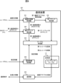
- FIG. 1 is a configuration diagram of a network system according to a first embodiment.
- FIG. 1 is a configuration diagram of a communication device according to a first embodiment.
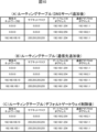
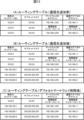
- Functional configuration diagram of a communication device according to the first embodiment 1A is a diagram showing a routing table according to the first embodiment, in which (A) shows a routing table before a communication destination is added, (B) shows a routing table after a communication destination is added, and (C) shows a routing table after a default gateway is deleted.
- 1 is a flowchart showing a table management process executed by a communication device according to a first embodiment; Flowchart showing the record registration process in FIG. 5 .
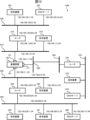
- FIG. 1 is a configuration diagram of a network system according to a second embodiment.
- FIG. 1 is a configuration diagram of a network system according to a third embodiment.
- FIG. 11A is a diagram showing a routing table according to a third embodiment, in which (A) shows a routing table before a communication destination is added, (B) shows a routing table after a communication destination is added, and (C) shows a routing table after a default gateway is deleted.
- FIG. 13 is an explanatory diagram of a procedure for updating a network setting in a communication device according to a fourth embodiment; A flowchart showing a setting correction process executed by a communication device according to a fourth embodiment.
- (Embodiment 1) 1 is a diagram showing a configuration of a network system 1000 according to the present embodiment.
- the network system 1000 includes a communication device 100, a router 210, a router 220, a terminal device 310, a terminal device 320, a terminal device 330, a terminal device 340, a terminal device 341, a communication network 510, a communication network 520, a communication network 530, and a communication network 540.
- the communication device 100 is a device that communicates with other devices using a communication adapter 151 and a communication adapter 161.
- the other devices will be referred to as the communication partner as appropriate.
- the communication device 100 selects a communication adapter to use for communication by referring to a routing table, which will be described later.
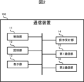
- the communication device 100 is, for example, a device that manages a facility. As shown in FIG. 2, the communication device 100 includes a control unit 11, a memory unit 12, a display unit 13, an operation reception unit 14, a first communication unit 15, and a second communication unit 16.
- the control unit 11 includes a CPU (Central Processing Unit), ROM (Read Only Memory), RAM (Random Access Memory), RTC (Real Time Clock), etc.
- the CPU is also called a central processing unit, central processing unit, processor, microprocessor, microcomputer, DSP (Digital Signal Processor), etc., and functions as a central processing unit that executes processes and calculations related to the control of the communication device 100.
- the CPU reads out programs and data stored in the ROM and uses the RAM as a work area to control the communication device 100.
- the RTC is, for example, an integrated circuit with a timekeeping function. The CPU can determine the current date and time from the time information read from the RTC.
- the memory unit 12 is equipped with non-volatile semiconductor memory such as flash memory, EPROM (Erasable Programmable ROM), and EEPROM (Electrically Erasable Programmable ROM), and serves as a so-called auxiliary storage device.
- the memory unit 12 stores programs and data used by the control unit 11 to execute various processes.
- the memory unit 12 also stores data generated or acquired by the control unit 11 executing various processes.
- the memory unit 12 stores a routing table, which will be described later.
- the display unit 13 displays various images according to the control of the control unit 11. For example, the display unit 13 displays a screen for accepting various operations from the user.
- the display unit 13 includes a touch screen, a liquid crystal display, etc.
- the operation acceptance unit 14 accepts various operations from the user and supplies information indicating the contents of the accepted operations to the control unit 11.
- the operation acceptance unit 14 includes a touch screen, a button, a lever, etc.
- the first communication unit 15 communicates with devices connected to the communication network 510 according to the control of the control unit 11.
- the first communication unit 15 has a function of connecting to the communication network 510, and communicates with the router 210, terminal device 310, etc., connected to the communication network 510.
- the first communication unit 15 has a communication adapter 151 that connects to the communication network 510 according to the TCP/IP standard.
- the communication adapter 151 is a communication interface that conforms to standards such as Wi-Fi (registered trademark) and Ethernet (registered trademark).
- the second communication unit 16 communicates with devices connected to the communication network 520 according to the control of the control unit 11.
- the second communication unit 16 has a function of connecting to the communication network 520, and communicates with the router 220, terminal device 320, etc., connected to the communication network 520.
- the second communication unit 16 includes a communication adapter 161 that connects to the communication network 520 according to the TCP/IP standard.
- the communication adapter 161 is a communication interface that conforms to standards such as Wi-Fi (registered trademark) and Ethernet (registered trademark).
- the router 210 is a communication device that connects the communication network 510 and the communication network 530.
- the router 210 relays data between the communication network 510 and the communication network 530.
- the router 210 includes a communication adapter (not shown) that connects to the communication network 510, and a communication adapter (not shown) that connects to the communication network 530.
- the router 210 functions as a gateway.
- the router 220 is a communication device that connects the communication network 520 and the communication network 540.
- the router 220 relays data between the communication network 520 and the communication network 540.
- the router 220 includes a communication adapter (not shown) that connects to the communication network 520, and a communication adapter (not shown) that connects to the communication network 540.
- the router 220 functions as a gateway.
- Terminal device 310 is a device connected to communication network 510.
- Terminal device 310 has a communication adapter (not shown) that connects to communication network 510.
- Terminal device 320 is a device connected to communication network 520.
- Terminal device 320 has a communication adapter (not shown) that connects to communication network 520.
- Terminal device 330 is a device connected to communication network 530.
- Terminal device 330 has a communication adapter (not shown) that connects to communication network 530.
- Terminal device 340 and terminal device 341 are devices connected to communication network 540.
- Terminal device 340 and terminal device 341 have a communication adapter (not shown) that connects to communication network 540.
- Communication networks 510, 520, 530, and 540 are different from one another. Each of communication networks 510, 520, 530, and 540 is, for example, a wireless LAN or a wired LAN provided within a facility. Communication networks 510, 520, 530, and 540 are communication networks that transmit and receive data according to the TCP/IP standard.
- a routing table is a table that holds a list of paths to destinations in individual networks.
- the routing table contains records that include the destination network ID, subnet mask, gateway IP address, and communication adapter IP address.
- the destination network ID is the ID of the communication network to which the connection is made.
- the destination network ID is expressed in the same format as an IP address.
- IPv Internet Protocol Version 4 4
- the IP address may be expressed as a combination of four decimal numbers ranging from 0 to 255, or as a 32-bit binary number separated by 8 bits.
- the network ID will be referred to as a subnetwork where appropriate.
- a subnet mask is a numerical value used to distinguish between the network address portion and the host address portion in an IP address, and is used to extract the network address portion from an IP address.
- the network address portion is the address portion of an IP address that indicates the network.
- the host address portion is the address portion of an IP address that indicates a terminal.
- a subnet mask is expressed in decimal, hexadecimal, binary, etc.
- the gateway IP address is the IP address of the gateway used when connecting to the destination communications network.
- This gateway IP address is the IP address in the communications network of the source device as seen from the gateway.
- the communications adapter IP address is the IP address of the communications adapter used when connecting to the destination communications network.
- IP address of the communication device 100 in the communication network 510 (hereinafter, simply referred to as the "IP address of the communication device 100") is divided into a network address portion and a host address portion using a subnet mask.
- the IP address of the communication device 100 is "192.168.1.1” in decimal notation, and "11000000.10101000.00000001.00000001” in binary notation.
- the subnet mask is "255.255.255.0” in decimal notation, and "11111111.1111111.11111111.00000000” in binary notation.
- the number of "1"s in a binary subnet mask is called the subnet mask length.
- the subnet mask length of a decimal subnet mask of "255.255.255.0" is 24.
- the subnet mask length may be added to the end of the IP address or network ID.
- the IP address of communication device 100 may be written as "192.168.1.1/24"
- the network ID of communication network 510 may be written as "192.168.1.0/24".
- the IP address of the communication device 100 in the communication network 510 i.e., the IP address assigned to the communication adapter 151
- the IP address of the communication device 100 in the communication network 520 i.e., the IP address assigned to the communication adapter 161
- the IP address of the router 210 in the communication network 510 is "192.168.1.254/24".
- the IP address of the router 210 in the communication network 530 is "192.168.100.254/24".
- the IP address of the router 220 in the communication network 520 is "192.168.2.254/24".
- the IP address of the router 220 in the communication network 540 is "192.168.200.254/24".
- the IP address of terminal device 310 is "192.168.1.2/24".
- the IP address of terminal device 320 is "192.168.2.2/24".
- the IP address of terminal device 330 is "192.168.100.1/24".
- the IP address of terminal device 340 is "192.168.200.1/24".
- the IP address of terminal device 341 is "192.168.200.2/24".
- the network ID of communication network 510 is "192.168.1.0/24".
- the network ID of communication network 520 is "192.168.2.0/24”.
- the network ID of communication network 530 is "192.168.100.0/24”.
- the network ID of communication network 540 is "192.168.200.0/24”.
- the IP address of each device is assigned, for example, by a DHCP (Dynamic Host Configuration Protocol) server connected to each communication network.
- a DHCP Dynamic Host Configuration Protocol
- the IP address of communication device 100 in communication network 510 is assigned by a DHCP server (not shown) connected to communication network 510.
- the IP address of communication device 100 in communication network 520 is assigned by a DHCP server (not shown) connected to communication network 520.
- the DHCP servers connected to each communication network distribute the IP address of the default gateway to each device.
- a DHCP server (not shown) connected to communication network 510 distributes the IP address of router 210, which is set as the default gateway, to communication device 100.
- a DHCP server (not shown) connected to communication network 520 distributes the IP address of router 220, which is set as the default gateway, to communication device 100.
- communication device 100 registers both router 210 and router 220 as default gateways in the routing table.
- registration of a default gateway is achieved by registering a record corresponding to the default gateway.
- the default gateway is a gateway used when communicating with a communication destination for which an individual route is not registered in the routing table. Note that specifying a default gateway corresponds to specifying a default route, and also corresponds to specifying a communication adapter for connecting to the default gateway.
- the default route is a route used when communicating with a communication destination for which an individual route is not registered in the routing table.
- the record for setting router 210 as the default gateway (hereinafter referred to as "record A") is a record with a destination network ID of "0.0.0.0", a subnet mask of "0.0.0.0”, a gateway IP address of "192.168.1.254”, and a communications adapter IP address of "192.168.1.1”.
- the record for setting router 220 as the default gateway (hereinafter referred to as “record B”) is a record with a destination network ID of "0.0.0.0", a subnet mask of "0.0.0.0”, a gateway IP address of "192.168.2.254", and a communications adapter IP address of "192.168.2.1".
- the communication device 100 can communicate with the communication partner in accordance with the TCP/IP standard without referring to a routing table. For example, when the communication device 100 communicates with a terminal device 310 connected to a communication network 510 to which the communication device 100 is connected, the communication device 100 can communicate with the terminal device 310 via a communication adapter 151 for connecting to the communication network 510. Also, when the communication device 100 communicates with a terminal device 320 connected to a communication network 520 to which the communication device 100 is connected, the communication device 100 can communicate with the terminal device 320 via a communication adapter 161 for connecting to the communication network 520.
- the communication device 100 refers to a routing table in accordance with the TCP/IP standard to determine the route to the communication partner.
- the router 210 or router 220 that receives this packet transmits the packet appropriately to the communication partner. Therefore, the communication device 100 only needs to appropriately determine the communication adapter to be used for communication with the communication partner.
- determining the route to the communication partner basically means determining the communication adapter to be used for communicating with the communication partner.
- the communication device 100 communicates with the communication partner using a communication adapter having a communication adapter ID included in the record with the longest subnet mask length among the records corresponding to the communication networks to which the communication partner is connected.
- the record corresponding to the communication network to which the communication partner is connected is a record in which the logical product of the communication partner's IP address and the subnet mask included in the record matches the destination network ID included in the record.
- record C a record with a destination network ID of "192.168.100.0", a subnet mask of "255.255.255.0", a gateway IP address of "192.168.1.254”, and a communication adapter IP address of "192.168.1.1” is registered in the routing table, and the communication device 100 communicates with the terminal device 330.
- the logical product of the terminal device 330's IP address "192.168.100.1” and the subnet mask of record C, "255.255.255.0", "192.168.100.0” matches the destination network ID of record C, "192.168.100.0". Therefore, record C is a record corresponding to the communication network to which the communication partner is connected.
- the routing table also has records A and B registered that correspond to the default gateway.
- the logical product "0.0.0.0" of the IP address "192.168.100.1” of the terminal device 330 and the subnet mask "0.0.0.0” of record A matches the destination network ID "0.0.0.0” of record A.
- the logical product "0.0.0.0” of the IP address "192.168.100.1” of the terminal device 330 and the subnet mask "0.0.0.0” of record B matches the destination network ID "0.0.0.0” of record B. Therefore, records A and B are records that correspond to the communication network to which the communication partner is connected.
- the communication device 100 determines that the communication adapter 151 having the IP address "192.168.1.1" of the communication adapter included in record C is the communication adapter to be used for communication with the terminal device 330.
- the communication device 100 identifies records A and B as records corresponding to the communication network to which the communication partner is connected.
- the subnet mask length of record A is 0, and the subnet mask length of record B is 0. Therefore, it is difficult for communication device 100 to decide whether to adopt record A or record B. In other words, it is difficult for communication device 100 to decide whether to adopt communication adapter 151 or communication adapter 161 as the communication adapter to use for communication with terminal device 330. And if communication device 100 adopts communication adapter 161 as the communication adapter to use for communication with terminal device 330, it will not be able to communicate with terminal device 330.
- the communication device 100 generates a record to be used for communication with the communication partner from communication destination information that the user can easily identify, and registers the generated record in the routing table.
- the communication destination information includes the IP address of the communication partner and identification information of the communication adapter to be used for communication with the communication partner. In other words, it is assumed that even a user who is not familiar with network configurations will be able to easily identify the IP address of the communication partner and the identification information of the communication adapter to be used for communication with the communication partner.
- the communication device 100 identifies the IP address of the gateway to be used for communication with the communication partner and the IP address of the communication adapter to be used for communication with the communication partner from the identification information of the communication adapter to be used for communication with the communication partner.
- the communication device 100 then generates a record in which the destination network ID is the IP address of the communication partner, the subnet mask is the full-bit subnet mask "255.255.255.255", the gateway IP address is the IP address of the gateway to be used for communication with the communication partner, and the communication adapter IP address is the IP address of the communication adapter to be used for communication with the communication partner.
- the communication device 100 acquires communication destination information from the user, including "192.168.100.1", which is the IP address of the terminal device 330 with which the communication is to be made, and identification information of the communication adapter 151 used to communicate with the terminal device 330.
- the communication device 100 identifies "192.168.1.1”, which is the IP address of the communication adapter 151, from the identification information of the communication adapter 151.
- the communication device 100 identifies "192.168.1.254", which is the IP address of the gateway used to communicate with the terminal device 330, from the IP address of the communication adapter 151.
- the communication device 100 generates a record (hereinafter referred to as "record D” as appropriate) with a destination network ID of "192.168.100.1", a subnet mask of "255.255.255.255”, a gateway IP address of "192.168.1.254”, and a communication adapter IP address of "192.168.1.1".
- the communication device 100 registers record D in the routing table.
- records A, B, and D are registered in the routing table.
- the communication device 100 communicates with the terminal device 330, it identifies record D, which has the longest subnet mask length among records A, B, and D, and determines the communication adapter 151 indicated by record D as the communication adapter to be used for communication with the terminal device 330.
- the destination network ID of record D is set to the IP address of the communication partner, rather than the ID of the communication network to be connected. Therefore, the method of using the routing table in this embodiment differs from the general method of using a routing table, but is a method that can be used within the scope of TCP/IP implementation.
- communication device 100 When communication device 100 communicates with a communication partner that is not connected to communication network 510 or communication network 520, it need only register in advance in the routing table a record that corresponds to this communication partner and is similar to record D. However, when there are an unspecified number of communication partners that are not connected to communication network 510 or communication network 520, it is not easy to register records that correspond to the unspecified number of communication partners in the routing table. Therefore, for an unspecified number of communication partners, it is preferable to communicate via a default gateway.
- communication device 100 it is preferable for communication device 100 to register a record corresponding to the communication partner connected to communication network 530 in the routing table, and communicate with the communication partner via the gateway indicated by this record.
- communication device 100 it is preferable for communication device 100 to communicate with communication partners connected to communication network 540 via a default gateway.
- record A indicating router 210 as the default gateway
- record B indicating router 220 as the default gateway
- record A is deleted from the routing table.
- communication device 100 can communicate with terminal device 340 and terminal device 341 via router 220, which record B indicates as the default gateway.
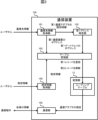
- the communication device 100 comprises a communication destination information acquisition unit 101, a first address identification unit 102, a table management unit 103, a specific information acquisition unit 104, and a communication unit 105.
- Each of these functions is realized by software, firmware, or a combination of software and firmware.
- the software and firmware are written as programs and stored in the ROM or memory unit 12.
- the CPU then executes the programs stored in the ROM or memory unit 12 to realize each of these functions.
- the communication device 100 is connected to a first communication network to which a first gateway is connected and a second communication network to which a second gateway is connected.
- the router 210 is an example of a first gateway
- the router 220 is an example of a second gateway.
- the communication network 510 is an example of a first communication network
- the communication network 520 is an example of a second communication network.
- the communication device 100 also includes a first communication adapter for connecting to a first communication network, and a second communication adapter for connecting to a second communication network.
- the communication adapter 151 is an example of a first communication adapter
- the communication adapter 161 is an example of a second communication adapter.
- the storage unit 12 also stores a routing table in which records including a destination network ID, a subnet mask, and a gateway IP address are registered.
- the storage unit 12 is an example of a storage means.
- the communication destination information acquisition unit 101 acquires communication destination information from a user.
- the communication destination information is information for identifying the IP address of the first communication device and the IP address of the first gateway.
- the communication destination information includes the IP address of the first communication device and identification information of the first communication adapter.
- the first communication device is a device connected to the communication device 100 via the first gateway, and is a communication partner of the communication device 100.
- the terminal device 330 is an example of a first communication device.
- the communication destination information acquisition unit 101 is an example of a communication destination information acquisition means.
- the first address identification unit 102 refers to a routing table to identify the IP address of the first gateway corresponding to the IP address of the first communication adapter. For example, the first address identification unit 102 identifies a record indicating a default gateway from among the records registered in the routing table.
- the record indicating a default gateway is a record in which the destination network ID and subnet mask are "0.0.0.0".
- the first address identification unit 102 identifies, from among the records indicating the default gateway, a record in which the IP address of the communication adapter matches the IP address of the first communication adapter.
- the first address identification unit 102 identifies the IP address of the gateway indicated by the identified record as the IP address of the first gateway.
- the first address identification unit 102 is an example of a first address identification means.
- the table management unit 103 registers the first record in the routing table.
- the first record is a record that includes the IP address of the first communication device as the destination network ID, includes a full-bit subnet mask as the subnet mask, and includes the IP address of the first gateway or identification information of the first communication adapter as the gateway IP address.
- the first record is a record for identifying the gateway or communication adapter used when communicating with the first communication device.
- the first communication network is a LAN, and it is possible to identify the IP address of the first gateway connected to the first communication network. Therefore, in this embodiment, the first record includes the IP address of the first gateway as the gateway IP address. Record D described above is an example of the first record.
- the table management unit 103 sets the IP address of the first communication device included in the communication destination information acquired by the communication destination information acquisition unit 101 as the destination network ID included in the first record.
- the table management unit 103 also sets a full-bit subnet mask as the subnet mask included in the first record.
- the table management unit 103 also sets the IP address of the first gateway identified by the first address identification unit 102 as the IP address of the gateway included in the first record.
- the table management unit 103 also updates the routing table to indicate the second route of the first and second routes as the default route.
- the first route is a route that passes through the first communications network.
- the second route is a route that passes through the second communications network.
- the table management unit 103 updates the routing table to indicate that communication is to be performed via the second communications network. Communicating via the second communications network corresponds to communicating via the second gateway.
- the table management unit 103 updates the routing table to indicate the second gateway as the default gateway.
- the table management unit 103 deletes the second record of the second and third records from the routing table.
- the second record is a record that indicates the first route as the default route.
- the third record is a record that indicates the second route as the default route.
- the default route is specified by specifying the default gateway.
- the second record is a record that indicates the first gateway as the default gateway.
- the third record is a record that indicates the second gateway connected to the second communication network as the default gateway.
- record A described above is an example of a second record
- record B described above is an example of a third record.
- records corresponding to communication partners that are not connected to the communication network to which communication device 100 is connected and cannot communicate via a default gateway are registered in the routing table.
- records corresponding to communication partners that are connected to the communication network to which communication device 100 is connected and records corresponding to communication partners that can communicate via a default gateway are not registered in the routing table.
- Table management unit 103 is an example of a table management means.
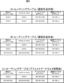
- FIG. 4(A) shows the routing table before a communication destination is added.
- the routing table before a communication destination is added includes a second record that indicates the first gateway as the default gateway and a third record that indicates the second gateway as the default gateway.
- the record in the first row is the second record
- the record in the second row is the third record.
- Figure 4 (B) shows the routing table after the communication destination has been added.
- the routing table after the communication destination has been added includes a second record that indicates the first gateway as the default gateway, a third record that indicates the second gateway as the default gateway, and a first record that indicates the gateway and communication adapter for communicating with the first communication device.
- the record in the first row is the second record
- the record in the second row is the third record
- the record in the third row is the first record.
- Figure 4(C) shows the routing table after the default gateway has been deleted.
- the routing table after the default gateway has been deleted includes a third record that indicates the second gateway as the default gateway, and a first record that indicates the gateway and communication adapter for communicating with the first communication device.
- the record in the first row is the third record
- the record in the second row is the first record.
- the communication device 100 can determine the communication adapter to be used for communication with the communication partner by referencing the routing table after the default gateway has been deleted. For example, when the communication device 100 communicates with the terminal device 330, which is the first communication device, it communicates with the terminal device 330 via the router 210 indicated as the gateway in the first record. Also, when the communication device 100 communicates with the terminal device 340, which is not the first communication device, it communicates with the terminal device 340 via the router 220 indicated as the default gateway in the third record. Similarly, when the communication device 100 communicates with the terminal device 341, which is not the first communication device, it communicates with the terminal device 341 via the router 220 indicated as the default gateway in the third record.
- the specification information acquisition unit 104 acquires specification information from the user.
- the specification information is information that specifies a default gateway.
- the specification information includes, for example, the IP address of the gateway specified as the default gateway.
- a gateway corresponds to a communication adapter for connecting to the gateway. Therefore, the specification information may be information that specifies a communication adapter for connecting to the default gateway.
- the specification information may include the IP address of a communication adapter for connecting to the default gateway.
- the table management unit 103 deletes from the routing table a record that corresponds to a gateway that is not specified as a default gateway by the specification information.
- the second gateway is specified as the default gateway by the specification information, and the second record that corresponds to the first gateway that is not specified as a default gateway by the specification information is deleted from the routing table.
- the communication unit 105 communicates with the first communication device via the first gateway indicated by the first record registered in the routing table.
- the communication unit 105 also communicates with the second communication device connected to the communication device 100 via the second gateway, which is the default gateway indicated in the routing table.
- Terminal device 340 and terminal device 341 are examples of the second communication device.
- the communication unit 105 communicates with the communication partner by referring to the routing table stored in the storage unit 12. Specifically, the communication unit 105 determines whether or not the logical product of the communication partner's IP address and subnet mask matches the destination network ID for each of all records included in the routing table. The communication unit 105 identifies the record with the longest subnet mask length among the records in which the logical product of the communication partner's IP address and subnet mask matches the destination network ID. The communication unit 105 communicates with the communication partner via the gateway indicated by the identified record using the communication adapter indicated by the identified record.
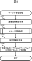
- the table management process is executed, for example, after the communication device 100 is connected to the communication network 510 and the communication network 520, and a record indicating the router 210 as the default gateway and a record indicating the router 220 as the default gateway are registered in the routing table.
- the control unit 11 included in the communication device 100 acquires communication destination information (step S101).
- the control unit 11 causes the display unit 13 to display a screen for inputting communication destination information.
- the user refers to this screen and inputs the IP address of the communication partner and the identification information of the communication adapter used for communication with the communication partner.
- the control unit 11 acquires communication destination information including the IP address of the communication partner and the identification information of the communication adapter.
- the control unit 11 acquires communication destination information for each of the multiple communication partners.
- control unit 11 When the control unit 11 completes the process of step S101, it executes a record registration process (step S102).
- the record registration process will be described in detail below with reference to FIG. 6.
- the control unit 11 determines whether the communication partner and the communication device 100 belong to the same communication network (step S201). For example, the control unit 11 determines whether the communication partner is connected to either communication network 510 or communication network 520. When the control unit 11 determines that the communication partner and the communication device 100 belong to the same communication network (step S201: YES), it completes the record registration process.
- control unit 11 determines that the communication partner and the communication device 100 do not belong to the same communication network (step S201: NO), it identifies the IP address of the communication adapter from the identification information of the communication adapter included in the communication destination information (step S202). For example, the control unit 11 identifies the IP address of the communication adapter from the identification information of the communication adapter based on the correspondence information stored in the storage unit 12. Note that if the identification information of the communication adapter is the IP address of the communication adapter, the processing of step S202 is not necessary.
- control unit 11 When the control unit 11 completes the processing of step S202, it identifies the IP address of the gateway from the IP address of the identified communication adapter (step S203). For example, the control unit 11 identifies a record corresponding to the default gateway from among the records registered in the routing table. The control unit 11 identifies a record from among the records corresponding to the default gateway in which the IP address of the communication adapter matches the IP address of the identified communication adapter. The control unit 11 identifies the IP address of the gateway indicated by the identified record.
- control unit 11 When the control unit 11 completes the process of step S203, it registers a record corresponding to the communication partner in the routing table (step S204).
- This record contains the IP address of the communication partner included in the communication destination information as the destination network ID, a full-bit subnet mask as the subnet mask, the IP address of the gateway identified in step S203 as the gateway IP address, and the IP address of the communication adapter identified in step S202 as the communication adapter IP address.
- control unit 11 When the control unit 11 completes the record registration process in step S102, it acquires the designated information (step S103). For example, the control unit 11 causes the display unit 13 to display a screen for inputting the designated information. The user refers to this screen and inputs the designated information. That is, the user inputs information on this screen indicating the gateway to be designated as the default gateway, or the communication adapter for connecting to the gateway to be designated as the default gateway. Note that, basically, a gateway other than the gateway indicated by the record individually registered in the routing table is designated as the default gateway.
- control unit 11 When the control unit 11 completes the processing of step S103, it deletes the records corresponding to the unspecified default gateway (step S104). In other words, the control unit 11 deletes from the routing table the records corresponding to the default gateways registered in the routing table other than the default gateway specified by the specification information.
- the specification information specifies router 220 as the default gateway
- the record specifying router 210 as the default gateway is deleted from the routing table.
- the control unit 11 completes the processing of step S104, it completes the table management processing.
- a first record is registered in the routing table, the first record including the IP address of the first communication device as the destination network ID, the full-bit subnet mask as the subnet mask, and the IP address of the first gateway or the identification information of the first communication adapter as the gateway IP address, and the routing table is updated to indicate the second route, which is a route via the second communication network, as the default route.
- the communication device 100 when the communication partner is a communication partner that can communicate via the first communication network, the communication device 100 communicates with the communication partner via the first communication network according to the first record registered in the routing table.
- the communication partner is a communication partner that can communicate via the second communication network
- the communication device 100 communicates with the communication partner via the second communication network according to the default route indicated in the routing table.
- the second record which is a record that indicates the first route as the default route
- the third record which is a record that indicates the second route as the default route
- the second record is deleted from the routing table. Therefore, according to this embodiment, the existence of multiple default routes is suppressed, and the communication device 100 is prevented from being unable to communicate with the communication partner.
- the first communication network and the second communication network are each a LAN, and it is possible to easily identify the IP address of the first gateway connected to the first communication network and the IP address of the second gateway connected to the second communication network. Therefore, according to this embodiment, there is no need to significantly change the way the routing table is used.
- a record for communicating with the first communication device is generated based on communication destination information for identifying the IP address of the first communication device and the IP address of the first gateway. Therefore, according to this embodiment, the effort required of the user to generate a record for communicating with the first communication device is reduced.
- a record for communicating with the first communication device is generated based on communication destination information including the IP address of the first communication device and identification information of the first communication adapter. Therefore, according to this embodiment, the effort required of the user to generate a record for communicating with the first communication device is further reduced.
- Embodiment 2 In the first embodiment, an example was described in which a user specifies a communication partner by the IP address of the communication partner when adding a record corresponding to the communication partner to the routing table. In the present embodiment, an example is described in which a user specifies a communication partner by the DNS (Domain Name System) host name of the communication partner when adding a record corresponding to the communication partner to the routing table. Note that the description of the same configuration and functions as those in the first embodiment will be omitted or simplified as appropriate.
- DNS Domain Name System
- a network system is configured so that a device can be recognized by its DNS hostname.
- a DNS hostname includes a domain name that identifies the network to which the device is connected, and a short hostname that identifies the device itself.
- a DNS hostname that includes a domain name and a short hostname is appropriately referred to as a long hostname. For example, if the short hostname is "test1" and the domain name is "aaa.test2", then the long hostname is "test1.aaa.test2".
- a DNS server is provided for each communication network. Therefore, when a communication partner is specified by a DNS host name, it is necessary to query the DNS server provided for the communication network to which the communication partner is connected for the IP address of the communication partner.
- this communication partner when adding a record corresponding to a communication partner to the routing table, this communication partner is basically connected to the communication device via a gateway that is not set as the default gateway. Therefore, the DNS server that knows the IP address of this communication partner is also basically connected to the communication device via a gateway that is not set as the default gateway. Therefore, before adding a record corresponding to the communication partner to the routing table, the communication device needs to add a record corresponding to the DNS server to the routing table.
- FIG. 7 is a diagram showing the configuration of a network system 1200 according to this embodiment.
- the network system 1200 includes a communication device 120, a router 210, a router 220, a terminal device 310, a terminal device 320, a terminal device 330, a terminal device 340, a terminal device 341, a DNS server 430, a DNS server 440, a communication network 510, a communication network 520, a communication network 530, and a communication network 540.
- the communication device 120 has a similar physical configuration to the communication device 100.
- DNS server 430 is a server that provides a mechanism for converting between DNS host names and IP addresses.
- DNS server 430 is connected to communication network 530. Therefore, DNS server 430 is capable of converting between DNS host names and IP addresses for terminal device 330 connected to communication network 530.
- DNS server 430 has a function for converting the DNS host name of terminal device 330 into the IP address of terminal device 330, and a function for converting the IP address of terminal device 330 into the DNS host name of terminal device 330.
- DNS server 440 is a server that provides a mechanism for converting DNS host names and IP addresses.
- DNS server 440 is connected to communication network 540. Therefore, DNS server 440 is capable of converting DNS host names and IP addresses for terminal device 340 and terminal device 341 connected to communication network 540.
- the communication device 120 comprises a communication destination information acquisition unit 101, a first address identification unit 102, a table management unit 103, a specific information acquisition unit 104, a communication unit 105, and a second address identification unit 106.
- Each of these functions is realized by software, firmware, or a combination of software and firmware.
- the software and firmware are written as programs and stored in the ROM or memory unit 12.
- the CPU then executes the programs stored in the ROM or memory unit 12 to realize each of these functions.
- the table management unit 103 adds a fourth record to the routing table.
- the fourth record is a record used when communicating with the first DNS server.
- the first DNS server is a device that allows the communication device 120 to perform name resolution for the first communication device, and is a device that associates the IP address of the first communication device with the host name of the first communication device.
- the fourth record is a record that includes the IP address of the first DNS server as the destination network ID, a full-bit subnet mask as the subnet mask, and the IP address of the first gateway as the gateway IP address.
- the terminal device 330 is an example of the first communication device
- the DNS server 430 is an example of the first DNS server
- the router 210 is an example of the first gateway.
- the communication destination information acquired by the communication destination information acquisition unit 101 includes the DNS host name of the first communication device and identification information of the first communication adapter.
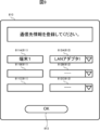
- Figure 9 shows a communication destination information registration screen 810 presented by the communication destination information acquisition unit 101 to acquire the communication destination information.
- the text box 811 and drop-down list 812 are an input interface for accepting communication destination information from the user.
- One pair of the text box 811 and drop-down list 812 corresponds to one communication partner.
- the text box 811 is a text box for inputting the DNS host name of the first communication device.
- FIG. 9 shows an example in which "Terminal 1" has been input as the DNS host name of the first communication device. If the first communication device is terminal device 330, "Terminal 1" is the DNS host name of terminal device 330.
- Drop-down list 812 is a drop-down list for specifying the identification information of the communication adapter to be used for communication with the first communication device. That is, in this embodiment, the user selects the identification information of the communication adapter to be used for communication with the first communication device from among the candidate identification information of the communication adapter presented by communication device 120.
- Figure 9 shows an example in which "LAN adapter 1" is specified as the identification information of the communication adapter to be used for communication with the first communication device. Note that when the first communication device is terminal device 330, "LAN adapter 1" is the identification information of communication adapter 151. Button 813 is pressed when input of communication destination information is completed.
- the second address determination unit 106 accesses the first DNS server and determines the IP address of the first communication device from the DNS host name of the first communication adapter included in the communication destination information. For example, if the first communication device is the terminal device 330, the second address determination unit 106 transmits the DNS host name of the terminal device 330 included in the communication destination information to the DNS server 430. The second address determination unit 106 then obtains the IP address of the terminal device 330 from the DNS server 430.
- the second address determination unit 106 is an example of a second address determination means.
- the table management unit 103 sets the IP address of the first communication device identified by the second address identification unit 106 as the destination network ID in the first record.
- the table management unit 103 also sets a full-bit subnet mask as the subnet mask in the first record.
- the table management unit 103 also sets the IP address of the first gateway identified by the first address identification unit 102 as the gateway IP address in the first record.
- FIG. 10(A) shows the routing table after the DNS server is added.
- the routing table after the DNS server is added includes a second record indicating the first gateway as the default gateway, a third record indicating the second gateway as the default gateway, and a fourth record indicating a gateway and a communication adapter for communicating with the first DNS server.
- the record in the first row is the second record
- the record in the second row is the third record
- the record in the third row is the fourth record.
- FIG. 10(B) shows the routing table after the communication destination is added.
- the routing table after the communication destination is added includes a second record indicating the first gateway as the default gateway, a third record indicating the second gateway as the default gateway, a fourth record indicating the gateway and communication adapter for communicating with the first DNS server, and a first record indicating the gateway and communication adapter for communicating with the first communication device.
- the record in the first row is the second record
- the record in the second row is the third record
- the record in the third row is the fourth record
- the record in the fourth row is the first record.
- Figure 10(C) shows the routing table after the default gateway has been deleted.
- the routing table after the default gateway has been deleted includes a third record that indicates the second gateway as the default gateway, a fourth record that indicates the gateway and communication adapter for communicating with the first DNS server, and a first record that indicates the gateway and communication adapter for communicating with the first communication device.
- the record in the first row is the third record
- the record in the second row is the fourth record
- the record in the third row is the first record.
- the communication device 120 generates a routing table after deleting the default gateway by deleting the second record that indicates the first gateway as the default gateway from the routing table after the communication destination has been added.
- the communication device 120 can determine the communication adapter to be used for communication with the communication partner by referring to the routing table after the default gateway has been deleted.
- the table management process executed by the communication device 120 will be described with reference to the flowchart in FIG. 11.
- the table management process is executed, for example, after the communication device 120 is connected to the communication networks 510 and 520, and a record indicating the router 210 as the default gateway and a record indicating the router 220 as the default gateway are registered in the routing table.
- the control unit 11 acquires communication destination information for communicating with the first DNS server (step S301). That is, the control unit 11 acquires communication destination information capable of identifying the IP address of the first DNS server and the IP address of the gateway used for communication with the first DNS server. Note that, if an IP address is assigned to each device by a DHCP server (not shown), the communication device 120 can acquire the IP address of the first DNS server and the IP address of the gateway used for communication with the first DNS server from the DHCP server (not shown).
- the IP address of the first DNS server and the IP address of the gateway used for communication with the first DNS server are stored in the memory unit 12 provided in the communication device 120. Therefore, the control unit 11 can obtain communication destination information with the first DNS server as the communication partner from the memory unit 12. In other words, the control unit 11 does not need to obtain communication destination information with the first DNS server as the communication partner from the user.
- control unit 11 When the control unit 11 completes the process of step S303, it identifies the IP address of the communication partner from the DNS host name of the communication partner (step S304). For example, the control unit 11 transmits the DNS host name of the communication partner to the first DNS server and obtains the IP address of the communication partner from the first DNS server.
- FIG. 12 is a diagram showing the configuration of a network system 1300 according to this embodiment.
- the network system 1300 includes a communication device 130, a router 210, a router 220, a router 270, a terminal device 310, a terminal device 320, a terminal device 330, a terminal device 340, a terminal device 341, a terminal device 370, a DNS server 430, a DNS server 440, a DNS server 470, a communication network 510, a communication network 520, a communication network 530, a communication network 540, a communication network 550, a communication network 560, and a communication network 570.
- the third communication unit communicates with devices connected to the communication network 550 in accordance with the control of the control unit 11.
- the third communication unit includes a communication adapter 171 that connects to the communication network 550 in accordance with the TCP/IP standard.
- the communication adapter 171 is a communication interface that complies with standards such as LTE (Long Term Evolution), 4G (4th Generation), and 5G (5th Generation).
- the router 270 is a communication device that connects the communication networks 560 and 570.
- the router 270 relays data between the communication networks 560 and 570.
- the router 270 includes a communication adapter (not shown) that connects to the communication network 560, and a communication adapter (not shown) that connects to the communication network 570.
- Terminal device 370 is a device connected to communication network 570.
- Terminal device 370 is equipped with a communication adapter (not shown) that connects to communication network 570.
- DNS server 470 is a server that provides a mechanism for converting between DNS host names and IP addresses.
- DNS server 470 is connected to communication network 570. Therefore, DNS server 470 is capable of converting between DNS host names and IP addresses for terminal devices 370 connected to communication network 570.
- Communication networks 510, 520, 530, 540, 550, 560, and 570 are different communication networks.
- Each of communication networks 510, 520, 530, and 540 is, for example, a wireless LAN or a wired LAN provided within a facility.
- Communication network 550 is, for example, a mobile phone network.
- Communication network 560 is, for example, the Internet.
- Communication network 570 is, for example, a wireless LAN or a wired LAN provided in another facility.
- Communication network 550 and communication network 570 are connected to each other. Note that base stations, switching centers, etc. are not shown in FIG. 12.
- Communication networks 510, 520, 530, 540, 550, 560, and 570 are communication networks that transmit and receive data according to the TCP/IP standard.
- communication device 130 can communicate with communication partners installed in other facilities via communication network 550, which is a mobile phone network, and communication network 560, which is the Internet.
- the communication networks connected to communication device 130 are communication network 510, communication network 520, and communication network 550. Therefore, in this embodiment, it is preferable that one of the three routes, the route via communication network 510, the route via communication network 520, and the route via communication network 550, is set as the default route, and the other routes are not set as the default route.
- communication device 130 can determine the route to be set as the default route based on the specification information acquired from the user by specification information acquisition unit 104.
- the specification information includes information indicating the router corresponding to the route to be set as the default route, the communication adapter corresponding to the route to be set as the default route, etc.
- the user prefferably sets the route used for communication with an unspecified number of communication partners, or the route used for communication with the largest number of communication partners, as the default route. For example, if the number of communication partners via communication network 550 is greater than the number of communication partners via communication network 510 and the number of communication partners via communication network 520, it is preferable to set the route via communication network 550 as the default route.
- the communication device 130 is connected to a first communication network, a second communication network, and a third communication network.
- each of the first communication network and the third communication network is a LAN
- the second communication network is a mobile phone network. Therefore, in this embodiment, a first gateway connected to the first communication network and a third gateway connected to the third communication network are assumed, but a second gateway connected to the second communication network is not assumed.
- the communication device 130 includes a first communication adapter for connecting to the first communication network, a second communication adapter for connecting to the second communication network, and a third communication adapter for connecting to the third communication network.
- Communication network 510 is an example of a first communication network.
- Communication network 520 is an example of a third communication network.
- Communication network 550 is an example of a second communication network.
- Communication adapter 151 is an example of a first communication adapter.
- Communication adapter 161 is an example of a third communication adapter.
- Communication adapter 171 is an example of a second communication adapter.
- Router 210 is an example of a first gateway.
- Router 220 is an example of a third gateway.
- the table management unit 103 registers in the routing table a first record for communicating with the first communication device.
- the first communication device is a device connected to the communication device 130 via the first gateway.
- the table management unit 103 also registers in the routing table a fifth record for communicating with the third communication device.
- the third communication device is a device connected to the communication device 130 via the third gateway.
- the table management unit 103 does not register in the routing table a record for communicating with the second communication device.
- the terminal device 330 is an example of a first communication device.
- the terminal devices 340 and 341 are examples of a third communication device.
- the terminal device 370 is an example of a second communication device.
- the first record is a record that includes the IP address of the first communication device as the destination network ID, includes a full-bit subnet mask as the subnet mask, and includes the IP address of the first gateway or identification information of the first communication adapter as the gateway IP address.
- the first record includes the IP address of the first gateway as the gateway IP address.
- the table management unit 103 can generate the first record based on communication destination information related to the first communication device obtained from the user.
- the table management unit 103 updates the routing table so that the second route out of the first route, the second route, and the third route is indicated as the default route.
- the first route is a route that passes through the first communication network.
- the second route is a route that passes through the second communication network.
- the third route is a route that passes through the third communication network.
- the table management unit 103 deletes the second and sixth records from the routing table out of the second, third, and sixth records.
- the second record is a record that indicates the first route as a default route.
- the third record is a record that indicates the second route as a default route.
- the sixth record is a record that indicates the third route as a default route.
- the second record is a record that indicates the first gateway as a default gateway.
- the third record is a record that indicates the second communication adapter as a default gateway.
- the sixth record is a record that indicates the third gateway as a default gateway.
- the first communication network and the third communication network are each a LAN, a first gateway connected to the first communication network and a third gateway connected to the third communication network are assumed. Therefore, for the first communication network and the third communication network, a default gateway and a default route are specified by the gateway. For example, for the first communication network, the IP address of the first gateway is adopted as the IP address of the gateway. Similarly, for the third communication network, the IP address of the third gateway is adopted as the IP address of the gateway.
- the second communication network is a mobile phone network
- a second gateway connected to the second communication network is not assumed. Therefore, for the second communication network, a default gateway and a default route are specified by the communication adapter.
- the identification information of the second communication adapter is used as the IP address of the gateway.
- the communication adapter takes the place of the gateway. For example, in the routing table, the identification information of the communication adapter is used instead of the IP address of the gateway for the second communication network.
- FIG. 13(A) shows the routing table before a communication destination is added.
- the routing table before a communication destination is added includes a second record indicating the first gateway as the default gateway, a third record indicating the second communication adapter as the default gateway, and a sixth record indicating the third gateway as the default gateway.
- the record in the first row is the second record
- the record in the second row is the third record
- the record in the third row is the sixth record.
- the gateway IP address and the communication adapter IP address are not assumed for the second communication network. Therefore, for the second communication network, the identification information of the communication adapter is used as the gateway IP address and the communication adapter IP address.
- the destination network ID and subnet mask are "0.0.0.0”
- the gateway IP address and the communication adapter IP address are the "cellular line interface", which is the identification information of the communication adapter 171.
- FIG. 13(B) shows the routing table after the communication destination is added.
- the routing table after the communication destination is added includes a second record indicating the first gateway as the default gateway, a third record indicating the second communication adapter as the default gateway, a sixth record indicating the third gateway as the default gateway, a first record indicating the gateway and communication adapter for communicating with the first communication device, and a fifth record indicating the gateway and communication adapter for communicating with the third communication device.
- the record in the first row is the second record
- the record in the second row is the third record
- the record in the third row is the sixth record
- the record in the fourth row is the first record
- the records in the fifth and sixth rows are the fifth record.
- FIG. 13(C) shows the routing table after the default gateway has been deleted.
- the routing table after the default gateway has been deleted includes a third record that indicates the second communication adapter as the default gateway, a first record that indicates the gateway and communication adapter for communicating with the first communication device, and a fifth record that indicates the gateway and communication adapter for communicating with the third communication device.
- the record in the first row is the third record
- the record in the second row is the first record
- the records in the third and fourth rows are the fifth record.
- the communication device 130 can determine the communication adapter to be used for communication with the communication partner by referring to the routing table after the default gateway has been deleted. For example, when the communication device 130 communicates with the terminal device 330, which is the first communication device, it communicates with the terminal device 330 via the router 210 indicated as the gateway in the first record. When the communication device 130 communicates with the terminal device 340 or terminal device 341, which is the third communication device, it communicates with the terminal device 340 or terminal device 341 via the router 220 indicated as the gateway in the fifth record. When the communication device 130 communicates with the terminal device 370, which is the second communication device, it communicates with the terminal device 370 via the communication adapter 171 indicated as the default gateway in the third record.
- the user can specify the communication partner by the DNS host name of the communication partner. Therefore, before registering the first record for communicating with the first communication device in the routing table, the communication device 130 registers the fourth record for communicating with the first DNS server in the routing table. In addition, before registering the fifth record for communicating with the third communication device in the routing table, the communication device 130 registers the seventh record for communicating with the third DNS server in the routing table.
- the third DNS server is a DNS server that associates the IP address of the third communication device with the DNS host name of the third communication device.
- DNS server 440 is an example of a third DNS server.
- the seventh record is a record that includes the IP address of the third DNS server as the destination network ID, a full-bit subnet mask as the subnet mask, and the IP address of the third gateway as the gateway IP address.
- the communication device 130 when the communication partner is a communication partner that can communicate via the first communication network, the communication device 130 communicates with the communication partner via the first gateway indicated by the first record registered in the routing table.
- the communication partner when the communication partner is a communication partner that can communicate via the third communication network, the communication device 130 communicates with the communication partner via the third gateway indicated by the fifth record registered in the routing table.
- the communication partner is a communication partner that can communicate via the second communication network, the communication device 130 communicates with the communication partner via the second communication adapter indicated as the default gateway in the routing table.
- the second record and the sixth record are deleted from the routing table. Therefore, according to this embodiment, the existence of multiple default routes is suppressed, and the communication device 130 is prevented from being unable to communicate with the communication partner.
- the first communication network and the third communication network are each a LAN, and the second communication network is a mobile phone network.
- the second communication adapter is treated as a gateway. Therefore, according to this embodiment, there is no need to change the way the routing table is used significantly.
- the communication device 140 includes, as software, an operating system 20, network management software 30, setting modification software 40, and a communication adapter driver 50. Note that, as hardware, the communication device 140 has the same configuration as the communication device 100.
- the operating system 20 is basic software that manages the entire computer system in the communication device 140.
- the operating system 20 is software that implements functions for the basic management and control of the communication device 140, as well as basic functions commonly used by many pieces of software.
- the operating system 20 manages the routing table 60 in which the network settings of the communication device 140 are registered.
- the routing table 60 is a table in which records including a destination network ID, a subnet mask, and a gateway IP address are registered.
- the routing table 60 is stored, for example, in the storage unit 12.
- the operating system 20 detects a change in the network settings made by the network management software 30, it notifies the setting modification software 40 of the change in the network settings.
- the network management software 30 is software that manages the network settings of the communication device 140 in cooperation with the operating system 20.
- the network management software 30 is software that starts up and remains resident immediately after the communication device 140 is started up.
- the network management software 30 changes the network settings of the communication device 140 by updating the routing table 60.
- the network settings performed by the network management software 30 include automatic settings by the DHCP server 70 and manual settings by the user 80.
- the network settings of the communication device 140 will be referred to simply as network settings, where appropriate.
- the setting modification software 40 is application software that works with the operating system 20 to modify the network settings of the communication device 140.
- Application software is software that runs on the operating system 20, and is software that is developed and used for specific functions and purposes.
- the setting modification software 40 is software that starts up immediately after the communication device 140 is started up, and remains resident.
- the setting modification software 40 can constantly receive various notifications from the operating system 20.
- the setting modification software 40 modifies the network settings of the communication device 140 by updating the routing table 60.
- the setting modification software 40 detects duplicate registration of a default gateway, it deletes the unnecessary default gateway and registers the necessary communication destination. Specifically, when the setting modification software 40 receives notification of a change in the network settings from the operating system 20, it determines whether or not multiple gateways are indicated as default gateways in the network settings. If the setting modification software 40 determines that multiple gateways are indicated as default gateways, it modifies the network settings so that only the specified gateway of the multiple gateways is indicated as the default gateway.
- the setting modification software 40 modifies the network settings so that only the specified gateway is indicated as the default gateway, it modifies the network settings so that the first communication device and the communication device 140 can communicate.
- the first communication device is a device that is connected to the communication device 140 via a first gateway that is not the specified gateway among multiple gateways. Note that modifying the network settings so that only the specified gateway is indicated as the default gateway corresponds to modifying the network settings so that the specified route, which is a route that passes through the specified gateway, is indicated as the default route.
- the setting modification software 40 When the setting modification software 40 receives a notification of a change in network settings from the operating system 20, and if the first route and the second route are indicated as default routes in the routing table 60, the setting modification software 40 registers the first record in the routing table 60 and updates the routing table 60 to indicate the second route as the default route.
- the second route is the specified route described above.
- the first route is a route that does not go through the specified gateway, but goes through the first gateway.
- the specified gateway is the router 220
- the first route is a route that goes through the router 210
- the second route is a route that goes through the router 220.
- the first record is as shown in the first embodiment. That is, the first record includes the IP address of the first communication device as the destination network ID. The first record also includes a full-bit subnet mask as the subnet mask. The first record also includes the IP address of the first gateway as the gateway IP address, or identification information of the first communication adapter, which is a communication adapter for connecting the communication device 140 to the first gateway among the multiple communication adapters.
- the first communication device is the terminal device 330
- the first communication adapter is the communication adapter 151.
- the setting modification software 40 also registers information indicating the first record and information indicating the second route, which is the specified route, as the default route in a recovery file stored in the storage unit 12.
- the setting modification software 40 executes a recovery process when the network management software 30 deletes the first record from the routing table 60 and updates the routing table 60 to indicate multiple routes including the first route and the second route as the default route.
- the setting modification software 40 registers the first record in the routing table 60 based on the recovery file, and updates the routing table 60 to indicate the second route, which is the specified route, as the default route.
- the communication adapter driver 50 is a device driver for the communication adapter 151 and the communication adapter 161.
- the communication adapter driver 50 is software that enables the operating system 20 to control the communication adapter 151 and the communication adapter 161 as hardware provided in the communication device 140.
- the communication adapter driver 50 has functions such as sending and receiving packets, notifying link up, and notifying link down.
- Link up means that the communication device 140 is connected to another device and is in a state where the communication device 140 can communicate with the other device.
- Link down means that the communication device 140 is not connected to the other device and is in a state where the communication device 140 cannot communicate with the other device.
- the network management software 30 functions as a DHCP client and automatically configures the network based on information received from the DHCP server 70, which is a DHCP server. For example, in automatic configuration in the communication network 510, the network management software 30 receives the IP address of the communication device 140 in the communication network 510 from the DHCP server 70, and registers the received IP address of the communication device 140.
- the network management software 30 also registers the router 210, which is the default gateway specified by the DHCP server 70, in the routing table 60.
- the network management software 30 registers the new default gateway in the routing table 60 even if another default gateway has already been registered in the routing table 60.
- the other default gateway is, for example, the router 220 in the communication network 520.
- the network settings are updated via the operating system 20.
- the network management software 30 and the setting modification software 40 can update the network settings using commands prepared by the operating system 20.
- the commands include a command to register the IP address of a communication adapter, a command to delete the IP address of a communication adapter, a command to add a default gateway, a command to delete a default gateway, a command to add a communication destination, a command to delete a communication destination, a command to obtain a registered default gateway, etc.
- the operating system 20 notifies the setting modification software 40 that the network settings have been updated.
- updating the routing table 60 corresponds to updating the network settings. Therefore, when the routing table 60 is updated, the operating system 20 notifies the setting modification software 40 that the routing table 60 has been updated.
- the network management software 30 updates the routing table 60
- the operating system 20 notifies the setting modification software 40 that the routing table 60 has been updated.
- the notification content by the operating system 20 can be adjusted as appropriate.
- the notification content may be that the routing table 60 has been updated, that a default gateway has been added to the routing table 60, or the IP address of the default gateway that has been added to the routing table 60.
- the setting modification software 40 When the setting modification software 40 receives a notification from the operating system 20 that a default gateway has been added to the routing table 60, it checks whether or not there are duplicate registrations of the default gateway. For example, the setting modification software 40 identifies the default gateways registered in the routing table 60 using a command to obtain the default gateways registered in the routing table 60. If the setting modification software 40 determines that multiple default gateways are registered in the routing table 60, it executes the table management process described in the first embodiment.
- the setting modification software 40 obtains from the user specification information that specifies a default gateway and communication destination information that indicates communication destinations that can be communicated with via unspecified default gateways. In the table management process, the setting modification software 40 deletes the unspecified default gateways and adds communication destinations that can be communicated with via unspecified default gateways.
- the setting modification software 40 uses a command to delete a default gateway to delete an unspecified default gateway from the routing table 60.
- the setting modification software 40 also uses a command to add a communication destination to the routing table 60, adding a communication destination that can be communicated with via an unspecified default gateway.
- the user 80 is, for example, a network administrator.
- the network management software 30 performs network settings based on information acquired from the user 80.
- the network management software 30 updates the contents of a configuration file based on the information acquired from the user 80, and updates the routing table 60 according to the contents of the configuration file.
- the configuration file is a file that holds network settings, and is stored in the storage unit 12, for example.
- the network management software 30 registers multiple default gateways in the routing table 60.
- the operating system 20 notifies the configuration modification software 40 that a default gateway has been added to the routing table 60.
- the configuration modification software 40 receives notification from the operating system 20 that a default gateway has been added to the routing table 60, it checks whether or not there are duplicate registrations of the default gateway.
- the configuration modification software 40 determines that multiple default gateways are registered in the routing table 60, it executes the table management process described in the first embodiment.
- the routing table 60 is appropriately corrected. Specifically, the unspecified default gateway is deleted from the routing table 60, and a communication destination that can be communicated with via the unspecified default gateway is registered in the routing table 60. As a result, the occurrence of communication failures is suppressed.
- the communication adapter driver 50 notifies the operating system 20 of the link down.
- the operating system 20 notifies the network management software 30 of the link down.
- the network management software 30 receives the link down notification from the operating system 20, it deletes information related to the linked down communication adapter 151 from the network settings. For example, the network management software 30 deletes the IP address of the communication adapter 151 using a command to delete an IP address.
- the network management software 30 also uses a command to delete a communication destination to delete the communication destination that can be communicated with via the communication adapter 151 from the routing table 60.
- This deletion of the communication destination corresponds to the deletion of the first record.
- the operating system 20 may notify the setting modification software 40 that the communication destination has been deleted from the routing table 60. However, at this point, there is no duplicate registration of the default gateway. Therefore, even if the setting modification software 40 receives this notification from the operating system 20, it does not modify the routing table 60.
- the communication adapter driver 50 notifies the operating system 20 of a link-up.
- the operating system 20 notifies the network management software 30 of the link-up.
- the network management software 30 receives the link-up notification from the operating system 20, it adds information about the linked-up communication adapter 151 to the network settings.
- the network management software 30 obtains various information from the DHCP server 70 and updates the routing table 60 based on the obtained information. Specifically, for example, the network management software 30 uses a command to register an IP address to add the IP address of the communication adapter 151. The network management software 30 also uses a command to add a default gateway to add the router 210 connected to the communication adapter 151 to the routing table 60 as a default gateway.
- the network management software 30 acquires information written in a configuration file stored in the storage unit 12, and updates the network configuration based on the acquired information. Specifically, for example, the network management software 30 registers the IP address of the communication adapter 151 using a command to register an IP address. Furthermore, the network management software 30 adds the router 210 connected to the communication adapter 151 as a default gateway to the routing table 60 using a command to add a default gateway.
- the operating system 20 When a default gateway is registered in the routing table 60, the operating system 20 notifies the setting modification software 40 that a default gateway has been registered in the routing table 60.
- the setting modification software 40 receives notification of the registration of a default gateway from the operating system 20, it determines whether or not there is a duplicate registration of the default gateway. If the setting modification software 40 determines that there is a duplicate registration of the default gateway, it deletes the unspecified default gateway from the routing table 60 and adds to the routing table 60 communication destinations that can be communicated with via the unspecified default gateway.
- the setting modification software 40 can update the routing table 60 using the recovery file.
- the network configuration may be the configuration of the communication adapter provided in the communication device 140.
- the setting modification software 40 may determine that there is no difference between the network configuration before link-down and the network configuration after link-up.
- the setting modification software 40 executes the table management process before a link-down, it can write the network configuration, the specification information, and the communication destination information to a recovery file. That is, the recovery file records, for example, the network configuration before the link-down, the specification information before the link-down, the communication destination information before the link-down, etc.
- the setting modification software 40 can recover the contents of the routing table 60 based on the information written in the recovery file.
- the setting modification software 40 deletes from the routing table 60 any default gateways other than the default gateway specified by the specification information written in the recovery file.
- the setting modification software 40 also adds to the routing table 60 the communication destination indicated by the communication destination information written in the recovery file. This operation automatically restores the contents of the routing table 60 when a link down and link up occurs, preventing communication failures.
- the setting modification process is a process implemented as the setting modification software 40.
- the setting modification process is executed in response to, for example, a notification of a change in the network settings being sent from the operating system 20 to the setting modification software 40.
- the control unit 11 acquires the network settings (step S401). For example, the control unit 11 identifies the default gateway registered in the routing table 60 using a command to acquire the registered default gateway. After completing the processing of step S401, the control unit 11 determines whether or not multiple default gateways exist (step S402). In other words, the control unit 11 determines whether or not multiple default gateways are registered in the routing table 60.
- step S402 When the control unit 11 determines that there are not multiple default gateways (step S402: NO), it completes the setting correction process. On the other hand, when the control unit 11 determines that there are multiple default gateways (step S402: YES), it determines whether automatic recovery is possible (step S403). For example, the control unit 11 may determine that automatic recovery is possible if a recovery file is stored in the memory unit 12. Or, for example, the control unit 11 may determine that automatic recovery is possible if there is no difference between the current network configuration and the network configuration recorded in the recovery file.
- control unit 11 determines that automatic recovery is possible (step S403: YES), it reads information from the recovery file (step S404). Specifically, the control unit 11 reads the specification information and communication destination information from the recovery file. On the other hand, if the control unit 11 determines that automatic recovery is not possible (step S403: NO), it obtains the specification information from the user 80 (step S405). In other words, the control unit 11 accepts the specification of a default gateway from the user 80.
- control unit 11 When the control unit 11 completes the process of step S405, it acquires communication destination information from the user 80 (step S406). In other words, the control unit 11 accepts from the user 80 a designation of a communication destination with which communication can be made via a gateway that is not designated as a default gateway. When the control unit 11 completes the process of step S406, it writes the designation information and communication destination information to a recovery file (step S407).
- control unit 11 When the control unit 11 completes the processing of step S404 or step S407, it deletes the default gateway (step S408). Specifically, the control unit 11 uses a command to delete the default gateway to delete the default gateway that is not specified by the specification information from the routing table 60.
- control unit 11 When the control unit 11 completes the process of step S408, it adds the communication destination (step S409). Specifically, the control unit 11 uses a command to add a communication destination to add the communication destination indicated by the communication destination information to the routing table 60. When the control unit 11 completes the process of step S409, it completes the setting correction process.
- Patent Document 1 describes a technology for determining a communication path using a dummy address and determining the communication adapter to be used for communication.
- Patent Document 1 is a technology that deviates significantly from the implementation of TCP/IP, and requires complicated processing. For this reason, there is a demand for a technology that can prevent the continuation of a state in which multiple default gateways are registered in duplicate, with a simple configuration; in other words, a technology that can prevent the occurrence of communication failures with a simple configuration. According to this embodiment, it is possible to prevent the occurrence of communication failures with a simple configuration.
- this embodiment when multiple gateways are specified as default gateways in the network settings, the network settings are modified so that only a specified gateway among the multiple gateways is specified as the default gateway.
- This embodiment prevents multiple default gateways from being registered in duplicate and continuing. Therefore, this embodiment can prevent communication failures with a simple configuration.
- the setting modification software 40 uses a method to quickly resolve the duplicate registration of multiple default gateways.
- a method can be considered in which the operating system 20 or the network management software 30 is modified to prevent multiple default gateways from being registered in duplicate.
- modifying the operating system 20 affects various processes, so modifying the operating system 20 is not easy.
- the network management software 30 is deeply connected to the operating system 20. Modifying the network management software 30 corresponds to modifying the DHCP implementation. For this reason, modifying the network management software 30 is also not easy. In other words, software development is easy with the method of preparing setting modification software 40 without making changes to the operating system 20 and network management software 30, as in this embodiment.
- the setting correction software 40 when the setting correction software 40 receives a notification of a change in the network settings from the operating system 20, it quickly detects the duplicate registration of multiple default gateways and quickly resolves the duplicate registration of multiple default gateways. Therefore, according to this embodiment, the period during which multiple default gateways are duplicately registered is extremely short, and the possibility of a communication failure occurring is considered to be extremely low.
- the network settings are modified so that the first communication device connected via a gateway that is not designated as the default gateway and the communication device 140 can communicate.
- the routing table 60 is updated to indicate a designated route that is a route via a designated gateway as the default route, a first record for enabling communication between the first communication device and the communication device 140 is registered in the routing table 60. Therefore, according to this embodiment, it is possible to realize communication using multiple communication adapters while suppressing the occurrence of communication failures.
- the contents of the routing table 60 are automatically restored based on the recovery file.
- the first record is deleted from the routing table 60 and the routing table 60 is updated to indicate multiple routes as default routes
- the first record is registered in the routing table 60 based on the recovery file, and the routing table 60 is updated to indicate the specified route as the default route. Therefore, according to this embodiment, it is possible to prevent the occurrence of communication failures without causing any effort to the user.
- the number and types of communication networks connected to the communication device are not limited to those shown in embodiments 1-3. For example, four or more communication networks may be connected to the communication device. Also, one LAN and one mobile phone network may be connected to the communication device. Also, three LANs may be connected to the communication device. Below, Variation 1 and Variation 2 are shown as typical variations.
- the network system according to the first modification includes a first communication network which is a LAN and a second communication network which is a mobile phone network.
- the first communication network is, for example, the communication network 510 in the third embodiment.
- the second communication network is, for example, the communication network 550 in the third embodiment.
- the network system according to the first modification is basically a network system in which the communication network 520 is excluded from the network system according to the third embodiment.
- the second route which is a route via the second communication network is set as the default route.
- the first record is a record that includes the IP address of the first communication device as the destination network ID, a full-bit subnet mask as the subnet mask, and the IP address of the first gateway as the gateway IP address.
- the first communication device is, for example, the terminal device 330 in embodiment 3.
- the first gateway is, for example, the router 210 in embodiment 3.
- the second record is a record that indicates the first gateway as the default gateway.
- the third record is a record that indicates the second communication adapter as the default gateway.
- the second communication adapter is, for example, the communication adapter 171 in embodiment 3.
- a communication device when a communication device communicates with a first communication device, it communicates with the first communication device via a first communication network in accordance with a first record registered in the routing table. Also, in variant 1, when a communication device communicates with a second communication device connected to the communication device via a second communication network, it communicates with the second communication device via the second communication network in accordance with a default route indicated in the routing table.
- the second communication device is, for example, the terminal device 370 in embodiment 3.
- the network system according to the second modification includes a first communication network which is a mobile phone network and a second communication network which is a LAN.
- the first communication network is, for example, the communication network 550 in the third embodiment.
- the second communication network is, for example, the communication network 510 in the third embodiment.
- the network system according to the first modification is basically a network system in which the communication network 520 is excluded from the network system according to the third embodiment.
- the second route which is a route via the second communication network is set as the default route.
- the first record is a record that includes the IP address of the first communication device as the destination network ID, a full-bit subnet mask as the subnet mask, and identification information of the first communication adapter as the gateway IP address.
- the first communication device is, for example, the terminal device 370 in the third embodiment.
- the first communication adapter is, for example, the communication adapter 171 in the third embodiment.
- the second record is a record that indicates the first communication adapter as the default gateway.
- the third record is a record that indicates the second gateway connected to the second communication network as the default gateway.
- the second gateway is, for example, the router 210 in the third embodiment.
- the communication device when the communication device communicates with the first communication device, it communicates with the first communication device via the first communication network according to the first record registered in the routing table. Also, in variant 1, when the communication device communicates with the second communication device connected to the communication device via the second communication network, it communicates with the second communication device via the second communication network according to the default route indicated in the routing table.
- the second communication device is, for example, the terminal device 330 in embodiment 3.
- a method was described in which, among a plurality of records indicating default gateways, records other than one record indicating one specified default gateway are deleted.
- One default gateway may be indicated by the routing table by other methods. For example, a metric value may be included in the records registered in the routing table, and the metric value of the record indicating the specified default gateway may be set to the minimum value. In this case, among the records indicating the default gateway, records having a metric value other than the minimum value are not actually used.
- the record indicating the default route may be any record that can identify the communications adapter to be used when a record corresponding to the communication destination is not registered in the routing table.
- the third record may be the identifier of the second communications network instead of the identifier of the second communications adapter. This is because, even in such a configuration, the communications adapter to be used when a record corresponding to the communication destination is not registered in the routing table can be identified from the identifier of the second communications network indicated by the third record.
- a default gateway was specified by specification information.
- the default gateway may also be determined automatically. For example, a gateway not indicated by a record registered in the routing table corresponding to the communication partner may be set as the default gateway.
- the second communication adapter may be set as the default gateway.
- the communication adapter 171 is set as the default gateway.
- the router 210 or the router 220 may also be set as the default gateway. It is preferable that a router or communication adapter used for communication with an unspecified number of communication partners is set as the default gateway. For example, a router or communication adapter used for communication with communication partners whose IP addresses are difficult to identify may be set as the default gateway. Or, a router or communication adapter used for communication with the largest number of communication partners may be set as the default gateway.
- This disclosure is applicable to network systems that include multiple communication networks.
Landscapes
- Engineering & Computer Science (AREA)
- Computer Networks & Wireless Communication (AREA)
- Signal Processing (AREA)
- Data Exchanges In Wide-Area Networks (AREA)
Abstract
記憶部(12)は、宛先のネットワークIDとサブネットマスクとゲートウェイのIPアドレスとを含むレコードが登録されるルーティングテーブルを記憶する。テーブル管理部(103)は、宛先のネットワークIDとして第1通信ネットワークを経由して通信装置(100)に接続される第1通信装置のIPアドレスを含み、サブネットマスクとしてフルビットのサブネットマスクを含み、ゲートウェイのIPアドレスとして第1通信ネットワークに接続される第1ゲートウェイのIPアドレス又は第1通信アダプタの識別情報を含むレコードである第1レコードをルーティングテーブルに登録し、第2通信ネットワークを経由する経路である第2経路をデフォルトルートとして示すようにルーティングテーブルを更新する。かかる構成によれば、ユーザに手間をかけずに簡単な構成で通信経路を適切に決定することができる。
Description
本開示は、通信装置、ネットワークシステム、通信方法及びプログラムに関する。
近年、携帯電話網、無線LAN(Local Area Network)等の複数の通信ネットワークに接続可能な通信装置が知られている。このような通信装置は、対応する通信ネットワークに接続するための複数の通信アダプタを備える。通信装置は、基本的に、ルーティングテーブルを用いて通信相手が属するサブネットに対応する通信アダプタを特定し、特定した通信アダプタを用いて通信相手と通信する。
ここで、通信相手が属するサブネットがルーティングテーブルに登録されていない場合、デフォルトゲートウェイに接続するための通信アダプタが通信に用いられる。しかしながら、デフォルトゲートウェイに接続するための通信アダプタでは、通信装置を通信相手が属するサブネットに接続できない可能性がある。現在、このような問題を解決するための種々の技術が検討されている。例えば、特許文献1には、ダミーアドレスを用いて通信経路を決定し、通信に用いる通信アダプタを決定する技術が記載されている。
しかしながら、特許文献1に記載された技術は、TCP/IP(Transmission Control Protocol/Internet Protocol)の実装から大きく外れた技術であり、煩雑な処理を要する技術である。一方、TCP/IPの実装の範囲内において、通信相手が属するサブネットをルーティングテーブルに登録する方法も考えられる。しかしながら、この方法では、ユーザが、通信相手が属するサブネットを特定する必要があり、ユーザに多大な手間がかかる。このため、ユーザに手間をかけずに簡単な構成で通信経路を適切に決定することが可能な技術が望まれている。
本開示は、上記問題に鑑みてなされたものであり、ユーザに手間をかけずに簡単な構成で通信経路を適切に決定する通信装置、ネットワークシステム、通信方法及びプログラムを提供することを目的とする。
上記目的を達成するために、本開示に係る通信装置は、
第1通信ネットワークと第2通信ネットワークとに接続される通信装置であって、
前記第1通信ネットワークに接続するための第1通信アダプタと、
前記第2通信ネットワークに接続するための第2通信アダプタと、
宛先のネットワークIDとサブネットマスクとゲートウェイのIPアドレスとを含むレコードが登録されるルーティングテーブルを記憶する記憶手段と、
前記宛先のネットワークIDとして前記第1通信ネットワークを経由して前記通信装置に接続される第1通信装置のIPアドレスを含み、前記サブネットマスクとしてフルビットのサブネットマスクを含み、前記ゲートウェイのIPアドレスとして前記第1通信ネットワークに接続される第1ゲートウェイのIPアドレス又は前記第1通信アダプタの識別情報を含むレコードである第1レコードを前記ルーティングテーブルに登録し、前記第1通信ネットワークを経由する経路である第1経路と前記第2通信ネットワークを経由する経路である第2経路とのうち前記第2経路をデフォルトルートとして示すように前記ルーティングテーブルを更新するテーブル管理手段と、を備える。
第1通信ネットワークと第2通信ネットワークとに接続される通信装置であって、
前記第1通信ネットワークに接続するための第1通信アダプタと、
前記第2通信ネットワークに接続するための第2通信アダプタと、
宛先のネットワークIDとサブネットマスクとゲートウェイのIPアドレスとを含むレコードが登録されるルーティングテーブルを記憶する記憶手段と、
前記宛先のネットワークIDとして前記第1通信ネットワークを経由して前記通信装置に接続される第1通信装置のIPアドレスを含み、前記サブネットマスクとしてフルビットのサブネットマスクを含み、前記ゲートウェイのIPアドレスとして前記第1通信ネットワークに接続される第1ゲートウェイのIPアドレス又は前記第1通信アダプタの識別情報を含むレコードである第1レコードを前記ルーティングテーブルに登録し、前記第1通信ネットワークを経由する経路である第1経路と前記第2通信ネットワークを経由する経路である第2経路とのうち前記第2経路をデフォルトルートとして示すように前記ルーティングテーブルを更新するテーブル管理手段と、を備える。
本開示では、宛先のネットワークIDとして第1通信装置のIPアドレスを含み、サブネットマスクとしてフルビットのサブネットマスクを含み、ゲートウェイのIPアドレスとして第1ゲートウェイのIPアドレス又は第1通信アダプタの識別情報を含むレコードである第1レコードがルーティングテーブルに登録され、第2通信ネットワークを経由する経路である第2経路をデフォルトルートとして示すようにルーティングテーブルが更新される。従って、本開示によれば、ユーザに手間をかけずに簡単な構成で通信経路を適切に決定することができる。
以下、本開示の実施の形態について、図面を参照しながら詳細に説明する。なお、図中同一又は相当部分には同一符号を付す。
(実施の形態1)
図1は、本実施の形態に係るネットワークシステム1000の構成を示す図である。ネットワークシステム1000は、通信装置100と、ルータ210と、ルータ220と、端末装置310と、端末装置320と、端末装置330と、端末装置340と、端末装置341と、通信ネットワーク510と、通信ネットワーク520と、通信ネットワーク530と、通信ネットワーク540とを備える。
図1は、本実施の形態に係るネットワークシステム1000の構成を示す図である。ネットワークシステム1000は、通信装置100と、ルータ210と、ルータ220と、端末装置310と、端末装置320と、端末装置330と、端末装置340と、端末装置341と、通信ネットワーク510と、通信ネットワーク520と、通信ネットワーク530と、通信ネットワーク540とを備える。
通信装置100は、通信アダプタ151と通信アダプタ161とを用いて、他の装置と通信する装置である。以下、適宜、他の装置のことを通信相手という。通信装置100は、後述するルーティングテーブルを参照して、通信に用いる通信アダプタを選択する。通信装置100は、例えば、施設を管理する装置である。図2に示すように、通信装置100は、制御部11と、記憶部12と、表示部13と、操作受付部14と、第1通信部15と、第2通信部16とを備える。
制御部11は、CPU(Central Processing Unit)、ROM(Read Only Memory)、RAM(Random Access Memory)、RTC(Real Time Clock)等を備える。CPUは、中央処理装置、中央演算装置、プロセッサ、マイクロプロセッサ、マイクロコンピュータ、DSP(Digital Signal Processor)等とも呼び、通信装置100の制御に係る処理及び演算を実行する中央演算処理部として機能する。制御部11において、CPUは、ROMに格納されているプログラム及びデータを読み出し、RAMをワークエリアとして用いて、通信装置100を統括制御する。RTCは、例えば、計時機能を有する集積回路である。なお、CPUは、RTCから読み出される時刻情報から現在日時を特定可能である。
記憶部12は、フラッシュメモリ、EPROM(Erasable Programmable ROM)、EEPROM(Electrically Erasable Programmable ROM)等の不揮発性の半導体メモリを備えており、いわゆる補助記憶装置としての役割を担う。記憶部12は、制御部11が各種処理を実行するために使用するプログラム及びデータを記憶する。また、記憶部12は、制御部11が各種処理を実行することにより生成又は取得するデータを記憶する。記憶部12は、後述するルーティングテーブルを記憶する。
表示部13は、制御部11による制御に従って、各種の画像を表示する。例えば、表示部13は、ユーザから各種の操作を受け付けるための画面を表示する。表示部13は、タッチスクリーン、液晶ディスプレイ等を備える。操作受付部14は、ユーザから各種の操作を受け付け、受け付けた操作の内容を示す情報を制御部11に供給する。操作受付部14は、タッチスクリーン、ボタン、レバー等を備える。
第1通信部15は、制御部11による制御に従って、通信ネットワーク510に接続された装置と通信する。第1通信部15は、通信ネットワーク510に接続する機能を有し、通信ネットワーク510に接続された、ルータ210、端末装置310等と通信する。第1通信部15は、TCP/IPの規格に従って通信ネットワーク510に接続する通信アダプタ151を備える。通信アダプタ151は、Wi-Fi(登録商標)、Ethernet(登録商標)等の規格に適合した通信インターフェースである。
第2通信部16は、制御部11による制御に従って、通信ネットワーク520に接続された装置と通信する。第2通信部16は、通信ネットワーク520に接続する機能を有し、通信ネットワーク520に接続された、ルータ220、端末装置320等と通信する。第2通信部16は、TCP/IPの規格に従って通信ネットワーク520に接続する通信アダプタ161を備える。通信アダプタ161は、Wi-Fi(登録商標)、Ethernet(登録商標)等の規格に適合した通信インターフェースである。
ルータ210は、通信ネットワーク510と通信ネットワーク530とを接続する通信機器である。ルータ210は、通信ネットワーク510と通信ネットワーク530との間でデータを中継する。ルータ210は、通信ネットワーク510に接続する通信アダプタ(図示せず)と、通信ネットワーク530に接続する通信アダプタ(図示せず)とを備える。ルータ210は、ゲートウェイとしての機能を有する。
ルータ220は、通信ネットワーク520と通信ネットワーク540とを接続する通信機器である。ルータ220は、通信ネットワーク520と通信ネットワーク540との間でデータを中継する。ルータ220は、通信ネットワーク520に接続する通信アダプタ(図示せず)と、通信ネットワーク540に接続する通信アダプタ(図示せず)とを備える。ルータ220は、ゲートウェイとしての機能を有する。
端末装置310は、通信ネットワーク510に接続された装置である。端末装置310は、通信ネットワーク510に接続する通信アダプタ(図示せず)を備える。端末装置320は、通信ネットワーク520に接続された装置である。端末装置320は、通信ネットワーク520に接続する通信アダプタ(図示せず)を備える。
端末装置330は、通信ネットワーク530に接続された装置である。端末装置330は、通信ネットワーク530に接続する通信アダプタ(図示せず)を備える。端末装置340と端末装置341とは、通信ネットワーク540に接続された装置である。端末装置340と端末装置341とは、通信ネットワーク540に接続する通信アダプタ(図示せず)を備える。
通信ネットワーク510と通信ネットワーク520と通信ネットワーク530と通信ネットワーク540とは、互いに異なる通信ネットワークである。通信ネットワーク510と通信ネットワーク520と通信ネットワーク530と通信ネットワーク540とのそれぞれは、例えば、施設内に設けられた無線LAN又は有線LANである。通信ネットワーク510と通信ネットワーク520と通信ネットワーク530と通信ネットワーク540とは、TCP/IPの規格に従ってデータを送受信する通信ネットワークである。
次に、通信装置100がルーティングテーブルを用いて通信経路を特定する方法について説明する。ルーティングテーブルは、個々のネットワークの宛先への経路の一覧を保持するテーブルである。本実施の形態では、ルーティングテーブルは、宛先のネットワークIDと、サブネットマスクと、ゲートウェイのIPアドレスと、通信アダプタのIPアドレスとを含むレコードを含む。
宛先のネットワークIDは、接続先の通信ネットワークのIDである。宛先のネットワークIDは、IPアドレスと同様の形式で表現される。IPアドレスは、IPv(Internet Protocol Version)4の場合、0から255までの10進数表記の数字を4つ組み合わせることにより表現されてもよいし、8ビット毎に区切られた32ビットの2進数により表現されてもよい。以下、ネットワークIDのことを、適宜、サブネットという。
サブネットマスクは、IPアドレスにおけるネットワークアドレス部とホストアドレス部とを識別するための数値であり、IPアドレスからネットワークアドレス部を抽出するための数値である。ネットワークアドレス部は、IPアドレスのうちネットワークを示すアドレス部分である。ホストアドレス部は、IPアドレスのうち端末を表すアドレス部分である。サブネットマスクは、10進数、16進数、2進数等で表現される。
ゲートウェイのIPアドレスは、接続先の通信ネットワークに接続するときに用いるゲートウェイのIPアドレスである。このゲートウェイのIPアドレスは、このゲートウェイから見て接続元の装置側の通信ネットワークにおけるIPアドレスである。通信アダプタのIPアドレスは、接続先の通信ネットワークに接続するときに用いる通信アダプタのIPアドレスである。
以下、通信装置100の通信ネットワーク510におけるIPアドレス(以下、適宜、単に「通信装置100のIPアドレス」という。)を、サブネットマスクを用いてネットワークアドレス部とホストアドレス部とに分割する例について説明する。
本実施の形態では、通信装置100のIPアドレスは、10進数表記で「192.168.1.1」であり、2進数表記で「11000000.10101000.00000001.00000001」である。ここで、サブネットマスクが、10進数表記で「255.255.255.0」であり、2進数表記で「11111111.11111111.11111111.00000000」である場合を想定する。
2進数表記の通信装置100のIPアドレスと2進数表記のサブネットマスクとで論理積を取ると、2進数表記で「11000000.10101000.00000001.00000000」、10進数表記で「192.168.1.0」となる。この「192.168.1.0」が、通信装置100が属する通信ネットワーク510のネットワークIDである。このように、2進数表記のサブネットマスクにおいて、「1」に相当する部分がネットワークアドレス部であり、「0」に相当する部分がホストアドレス部である。
ここで、2進数表記のサブネットマスクにおける「1」の個数をサブネットマスク長という。例えば、10進数表記で「255.255.255.0」のサブネットマスクのサブネットマスク長は24である。IPv4におけるIPアドレス又はネットワークIDにおいてサブネットマスク長を表現するために、IPアドレス又はネットワークIDの末尾にサブネットマスク長を付加することがある。例えば、通信装置100のIPアドレスが「192.168.1.1/24」と表記され、通信ネットワーク510のネットワークIDが「192.168.1.0/24」と表記されることがある。
本実施の形態では、通信装置100の通信ネットワーク510におけるIPアドレス、つまり、通信アダプタ151に付与されるIPアドレスは、「192.168.1.1/24」である。通信装置100の通信ネットワーク520におけるIPアドレス、つまり、通信アダプタ161に付与されるIPアドレスは、「192.168.2.1/24」である。ルータ210の通信ネットワーク510におけるIPアドレスは、「192.168.1.254/24」である。
ルータ210の通信ネットワーク530におけるIPアドレスは、「192.168.100.254/24」である。ルータ220の通信ネットワーク520におけるIPアドレスは、「192.168.2.254/24」である。ルータ220の通信ネットワーク540におけるIPアドレスは、「192.168.200.254/24」である。
端末装置310のIPアドレスは、「192.168.1.2/24」である。端末装置320のIPアドレスは、「192.168.2.2/24」である。端末装置330のIPアドレスは、「192.168.100.1/24」である。端末装置340のIPアドレスは、「192.168.200.1/24」である。端末装置341のIPアドレスは、「192.168.200.2/24」である。
通信ネットワーク510のネットワークIDは、「192.168.1.0/24」である。通信ネットワーク520のネットワークIDは、「192.168.2.0/24」である。通信ネットワーク530のネットワークIDは、「192.168.100.0/24」である。通信ネットワーク540のネットワークIDは、「192.168.200.0/24」である。
各装置のIPアドレスは、例えば、各通信ネットワークに接続されたDHCP(Dynamic Host Configuration Protocol)サーバにより付与される。例えば、通信装置100の通信ネットワーク510におけるIPアドレスは、通信ネットワーク510に接続されたDHCPサーバ(図示せず)により付与される。また、通信装置100の通信ネットワーク520におけるIPアドレスは、通信ネットワーク520に接続されたDHCPサーバ(図示せず)により付与される。
また、各通信ネットワークに接続されたDHCPサーバは、デフォルトゲートウェイのIPアドレスを各装置に配布する。例えば、通信ネットワーク510に接続されたDHCPサーバ(図示せず)は、デフォルトゲートウェイに設定されるルータ210のIPアドレスを通信装置100に配布する。また、例えば、通信ネットワーク520に接続されたDHCPサーバ(図示せず)は、デフォルトゲートウェイに設定されるルータ220のIPアドレスを通信装置100に配布する。
この場合、通信装置100は、ルータ210とルータ220との双方をデフォルトゲートウェイとしてルーティングテーブルに登録する。本実施の形態では、デフォルトゲートウェイの登録は、デフォルトゲートウェイに対応するレコードの登録により実現される。デフォルトゲートウェイは、ルーティングテーブルに個別の経路が登録されていない通信先と通信するときに用いられるゲートウェイである。なお、デフォルトゲートウェイを指定することは、デフォルトルートを指定することに対応し、デフォルトゲートウェイに接続するための通信アダプタを指定することにも対応する。デフォルトルートは、ルーティングテーブルに個別の経路が登録されていない通信先と通信するときに用いられる経路である。
ルータ210をデフォルトゲートウェイに設定するためのレコード(以下、適宜「レコードA」という。)は、宛先のネットワークIDが「0.0.0.0」、サブネットマスクが「0.0.0.0」、ゲートウェイのIPアドレスが「192.168.1.254」、通信アダプタのIPアドレスが「192.168.1.1」であるレコードである。例えば、ルータ220をデフォルトゲートウェイに設定するためのレコード(以下、適宜「レコードB」という。)は、宛先のネットワークIDが「0.0.0.0」、サブネットマスクが「0.0.0.0」、ゲートウェイのIPアドレスが「192.168.2.254」、通信アダプタのIPアドレスが「192.168.2.1」であるレコードである。
通信装置100と通信相手とが同一の通信ネットワークに接続されている場合、通信装置100は、TCP/IPの規格に従って、ルーティングテーブルを参照することなく、通信相手と通信することができる。例えば、通信装置100は、通信装置100が接続されている通信ネットワーク510に接続された端末装置310と通信する場合、通信ネットワーク510に接続するための通信アダプタ151を介して端末装置310と通信することができる。また、例えば、通信装置100は、通信装置100が接続されている通信ネットワーク520に接続された端末装置320と通信する場合、通信ネットワーク520に接続するための通信アダプタ161を介して端末装置320と通信することができる。
一方、通信装置100と通信相手とが同一の通信ネットワークに接続されていない場合、通信装置100は、TCP/IPの規格に従って、ルーティングテーブルを参照して、通信相手までの経路を決定する。なお、通信装置100が通信相手に向けて適切な通信アダプタからパケットを送信した場合、このパケットを受信したルータ210又はルータ220が通信相手に向けてこのパケットを適切に送信する。従って、通信装置100は、通信相手との通信に用いる通信アダプタを適切に決定すればよい。つまり、本実施の形態では、通信相手までの経路を決定することは、基本的に、通信相手と通信するために用いる通信アダプタを決定することである。
通信装置100と通信相手とが同一の通信ネットワークに接続されていない場合、通信装置100は、通信相手が接続された通信ネットワークに対応するレコードのうち、サブネットマスク長が最長のレコードに含まれる通信アダプタのIDを有する通信アダプタを用いて通信相手と通信する。通信相手が接続された通信ネットワークに対応するレコードは、通信相手のIPアドレスとレコードに含まれるサブネットマスクとの論理積が、レコードに含まれる宛先のネットワークIDと一致するレコードである。
例えば、宛先のネットワークIDが「192.168.100.0」、サブネットマスクが「255.255.255.0」、ゲートウェイのIPアドレスが「192.168.1.254」、通信アダプタのIPアドレスが「192.168.1.1」であるレコード(以下、適宜「レコードC」という。)がルーティングテーブルに登録されており、通信装置100が端末装置330と通信する場合を想定する。この場合、端末装置330のIPアドレスである「192.168.100.1」とレコードCのサブネットマスクである「255.255.255.0」との論理積である「192.168.100.0」は、レコードCの宛先のネットワークIDである「192.168.100.0」と一致する。従って、レコードCは、通信相手が接続された通信ネットワークに対応するレコードである。
また、ルーティングテーブルには、デフォルトゲートウェイに対応するレコードA及びレコードBも登録されている。端末装置330のIPアドレスである「192.168.100.1」とレコードAのサブネットマスクである「0.0.0.0」との論理積である「0.0.0.0」は、レコードAの宛先のネットワークIDである「0.0.0.0」と一致する。同様に、端末装置330のIPアドレスである「192.168.100.1」とレコードBのサブネットマスクである「0.0.0.0」との論理積である「0.0.0.0」は、レコードBの宛先のネットワークIDである「0.0.0.0」と一致する。従って、レコードAとレコードBとは、通信相手が接続された通信ネットワークに対応するレコードである。
ここで、レコードAのサブネットマスク長は0であり、レコードBのサブネットマスク長は0であり、レコードCのサブネットマスク長は24である。従って、通信装置100は、レコードCに含まれる通信アダプタのIPアドレスである「192.168.1.1」を有する通信アダプタ151を、端末装置330との通信に用いる通信アダプタとして決定する。
しかしながら、ユーザが、通信相手が接続された通信ネットワークのネットワークIDを特定し、通信相手が接続された通信ネットワークに対応するレコードをルーティングテーブルに登録するのが困難である場合も多い。例えば、ユーザが、端末装置330が接続された通信ネットワーク530のネットワークIDを特定するのが困難である場合も多い。この場合、ユーザが、ルーティングテーブルにレコードCを登録することは困難である。この場合、通信装置100は、通信相手が接続された通信ネットワークに対応するレコードとして、レコードAとレコードBとを特定する。
しかしながら、レコードAのサブネットマスク長は0であり、レコードBのサブネットマスク長は0である。従って、通信装置100は、レコードAとレコードBとの何れを採用すべきか決定することが困難である。つまり、通信装置100は、端末装置330との通信に用いる通信アダプタとして、通信アダプタ151と通信アダプタ161との何れを採用するのか決定することが困難である。そして、通信装置100は、端末装置330との通信に用いる通信アダプタとして通信アダプタ161を採用すると、端末装置330と通信することができない。
そこで、本実施の形態では、通信装置100は、ユーザが容易に特定可能な通信先情報から、通信相手との通信に用いるレコードを生成し、生成したレコードをルーティングテーブルに登録する。本実施の形態では、通信先情報は、通信相手のIPアドレスと、通信相手との通信に用いる通信アダプタの識別情報とを含む。つまり、ネットワーク構成を熟知していないユーザでも、通信相手のIPアドレスと、通信相手との通信に用いる通信アダプタの識別情報とを、容易に特定できることを想定している。
通信装置100は、通信相手との通信に用いる通信アダプタの識別情報から、通信相手との通信に用いるゲートウェイのIPアドレスと、通信相手との通信に用いる通信アダプタのIPアドレスとを特定する。そして、通信装置100は、宛先のネットワークIDが通信相手のIPアドレス、サブネットマスクがフルビットのサブネットマスクである「255.255.255.255」、ゲートウェイのIPアドレスが通信相手との通信に用いるゲートウェイのIPアドレス、通信アダプタのIPアドレスが通信相手との通信に用いる通信アダプタのIPアドレスであるレコードを生成する。
例えば、上述した例では、通信装置100は、通信相手である端末装置330のIPアドレスである「192.168.100.1」と、端末装置330との通信に用いる通信アダプタ151の識別情報とを含む通信先情報をユーザから取得する。通信装置100は、通信アダプタ151の識別情報から、通信アダプタ151のIPアドレスである「192.168.1.1」を特定する。通信装置100は、通信アダプタ151のIPアドレスから、端末装置330との通信に用いるゲートウェイのIPアドレスである「192.168.1.254」を特定する。
そして、通信装置100は、宛先のネットワークIDが「192.168.100.1」、サブネットマスクが「255.255.255.255」、ゲートウェイのIPアドレスが「192.168.1.254」、通信アダプタのIPアドレスが「192.168.1.1」であるレコード(以下、適宜「レコードD」とする。)を生成する。通信装置100は、レコードDをルーティングテーブルに登録する。
この時、ルーティングテーブルには、レコードAとレコードBとレコードDとが登録されている。通信装置100は、端末装置330と通信する場合、レコードAとレコードBとレコードDとのうちサブネットマスク長が最長であるレコードDを特定し、レコードDにより示される通信アダプタ151を、端末装置330との通信に用いる通信アダプタとして決定する。レコードDの宛先のネットワークIDには、接続先の通信ネットワークのIDではなく、通信相手のIPアドレスが設定される。このため、本実施の形態におけるルーティングテーブルの使用方法は、一般的なルーティングテーブルの使用方法とは異なるが、TCP/IPの実装の範囲内で使用可能な方法である。
通信装置100は、通信ネットワーク510又は通信ネットワーク520に接続されていない通信相手と通信する場合、この通信相手に対応するレコードであって、レコードDと同様のレコードを、予めルーティングテーブルに登録しておけばよい。しかしながら、通信ネットワーク510又は通信ネットワーク520に接続されていない通信相手が不特定多数である場合、不特定多数の通信相手に対応するレコードをルーティングテーブルに登録することは容易ではない。そこで、不特定多数の通信相手については、デフォルトゲートウェイを介して通信することが好適である。
例えば、通信ネットワーク530に接続される通信相手が少数であり、通信ネットワーク540に接続される通信相手が不特定多数である場合を想定する。この場合、通信装置100は、通信ネットワーク530に接続される通信相手については、通信相手に対応するレコードをルーティングテーブルに登録し、このレコードが示すゲートウェイを介して通信相手と通信することが好適である。
一方、通信装置100は、通信ネットワーク540に接続される通信相手については、デフォルトゲートウェイを介して通信相手と通信することが好適である。この場合、デフォルトゲートウェイとしてルータ210を示すレコードAとデフォルトゲートウェイとしてルータ220を示すレコードBとのうち、レコードAをルーティングテーブルから削除する。例えば、通信装置100は、レコードBがデフォルトゲートウェイとして示すルータ220を介して、端末装置340及び端末装置341と通信することができる。
次に、図3を参照して、通信装置100の機能について説明する。通信装置100は、機能的には、通信先情報取得部101と、第1アドレス特定部102と、テーブル管理部103と、指定情報取得部104と、通信部105とを備える。これらの各機能は、ソフトウェア、ファームウェア、又は、ソフトウェアとファームウェアとの組み合わせによって実現される。ソフトウェア及びファームウェアは、プログラムとして記述され、ROM又は記憶部12に格納される。そして、CPUが、ROM又は記憶部12に記憶されたプログラムを実行することによって、これらの各機能を実現する。
なお、通信装置100は、第1ゲートウェイが接続される第1通信ネットワークと第2ゲートウェイが接続される第2通信ネットワークとに接続される。ルータ210は第1ゲートウェイの一例であり、ルータ220は第2ゲートウェイの一例である。また、通信ネットワーク510は第1通信ネットワークの一例であり、通信ネットワーク520は第2通信ネットワークの一例である。
また、通信装置100は、第1通信ネットワークに接続するための第1通信アダプタと、第2通信ネットワークに接続するための第2通信アダプタとを備える。通信アダプタ151は第1通信アダプタの一例であり、通信アダプタ161は第2通信アダプタの一例である。また、記憶部12は、宛先のネットワークIDとサブネットマスクとゲートウェイのIPアドレスとを含むレコードが登録されるルーティングテーブルを記憶する。記憶部12は、記憶手段の一例である。
通信先情報取得部101は、通信先情報をユーザから取得する。通信先情報は、第1通信装置のIPアドレスと第1ゲートウェイのIPアドレスとを特定するための情報である。本実施の形態では、通信先情報は、第1通信装置のIPアドレスと第1通信アダプタの識別情報とを含む。第1通信装置は、第1ゲートウェイを介して通信装置100に接続される装置であり、通信装置100の通信相手である。端末装置330は、第1通信装置の一例である。通信先情報取得部101は、通信先情報取得手段の一例である。
第1アドレス特定部102は、通信先情報に含まれる第1通信アダプタの識別情報から第1ゲートウェイのIPアドレスを特定する。第1通信アダプタの識別情報は、第1通信アダプタのIPアドレスでもよいし、第1通信アダプタの名称でもよい。第1アドレス特定部102は、例えば、記憶部12に記憶された対応関係情報に基づいて、第1通信アダプタの名称から第1通信アダプタのIPアドレスを特定することができる。対応関係情報は、第1通信アダプタのIPアドレスと第1通信アダプタの名称とを対応付ける情報である。
第1アドレス特定部102は、例えば、ルーティングテーブルを参照して、第1通信アダプタのIPアドレスに対応する第1ゲートウェイのIPアドレスを特定する。例えば、第1アドレス特定部102は、ルーティングテーブルに登録されたレコードのうち、デフォルトゲートウェイを示すレコードを特定する。デフォルトゲートウェイを示すレコードは、宛先のネットワークIDとサブネットマスクとが「0.0.0.0」であるレコードである。
第1アドレス特定部102は、デフォルトゲートウェイを示すレコードのうち、通信アダプタのIPアドレスが第1通信アダプタのIPアドレスと一致するレコードを特定する。第1アドレス特定部102は、特定したレコードが示すゲートウェイのIPアドレスを第1ゲートウェイのIPアドレスとして特定する。第1アドレス特定部102は、第1アドレス特定手段の一例である。
テーブル管理部103は、第1レコードをルーティングテーブルに登録する。第1レコードは、宛先のネットワークIDとして第1通信装置のIPアドレスを含み、サブネットマスクとしてフルビットのサブネットマスクを含み、ゲートウェイのIPアドレスとして第1ゲートウェイのIPアドレス又は第1通信アダプタの識別情報を含むレコードである。第1レコードは、第1通信装置と通信するときに用いるゲートウェイ又は通信アダプタを特定するためのレコードである。本実施の形態では、第1通信ネットワークはLANであり、第1通信ネットワークに接続される第1ゲートウェイのIPアドレスを特定することが可能である。このため、本実施の形態では、第1レコードは、ゲートウェイのIPアドレスとして第1ゲートウェイのIPアドレスを含む。上述したレコードDは、第1レコードの一例である。
テーブル管理部103は、第1レコードが含む宛先のネットワークIDとして、通信先情報取得部101が取得した通信先情報に含まれる第1通信装置のIPアドレスを設定する。また、テーブル管理部103は、第1レコードが含むサブネットマスクとして、フルビットのサブネットマスクを設定する。また、テーブル管理部103は、第1レコードが含むゲートウェイのIPアドレスとして、第1アドレス特定部102が特定した第1ゲートウェイのIPアドレスを設定する。
また、テーブル管理部103は、第1経路と第2経路とのうち第2経路をデフォルトルートとして示すようにルーティングテーブルを更新する。第1経路は、第1通信ネットワークを経由する経路である。第2経路は、第2通信ネットワークを経由する経路である。つまり、テーブル管理部103は、ルーティングテーブルに通信先に対応するレコードが登録されていないときに、第2通信ネットワークを介して通信することを示すようにルーティングテーブルを更新する。第2通信ネットワークを介して通信することは、第2ゲートウェイを介して通信することに対応する。本実施の形態では、テーブル管理部103は、第2ゲートウェイをデフォルトゲートウェイとして示すようにルーティングテーブルを更新する。
例えば、テーブル管理部103は、第1レコードをルーティングテーブルに登録した後、第2レコードと第3レコードとのうち第2レコードをルーティングテーブルから削除する。第2レコードは、第1経路をデフォルトルートとして示すレコードである。第3レコードは、第2経路をデフォルトルートとして示すレコードである。本実施の形態では、デフォルトゲートウェイの指定により、デフォルトルートを指定する。つまり、第2レコードは、第1ゲートウェイをデフォルトゲートウェイとして示すレコードである。また、第3レコードは、第2通信ネットワークに接続される第2ゲートウェイをデフォルトゲートウェイとして示すレコードである。
なお、上述したレコードAは第2レコードの一例であり、上述したレコードBは第3レコードの一例である。このように、ルーティングテーブルには、通信装置100が接続された通信ネットワークに接続されていない通信相手であって、デフォルトゲートウェイを介して通信可能でない通信相手に対応するレコードが登録される。一方、ルーティングテーブルには、通信装置100が接続された通信ネットワークに接続されている通信相手に対応するレコードと、デフォルトゲートウェイを介して通信可能な通信相手に対応するレコードとが登録されない。テーブル管理部103は、テーブル管理手段の一例である。
ここで、図4を参照して、テーブル管理部103により更新されるルーティングテーブルの内容について説明する。図4(A)に、通信先追加前のルーティングテーブルを示す。図4(A)に示すように、通信先追加前のルーティングテーブルは、第1ゲートウェイをデフォルトゲートウェイとして示す第2レコードと、第2ゲートウェイをデフォルトゲートウェイとして示す第3レコードとを含む。図4(A)において、1行目のレコードが第2レコードであり、2行目のレコードが第3レコードである。
図4(B)に、通信先追加後のルーティングテーブルを示す。図4(B)に示すように、通信先追加後のルーティングテーブルは、第1ゲートウェイをデフォルトゲートウェイとして示す第2レコードと、第2ゲートウェイをデフォルトゲートウェイとして示す第3レコードと、第1通信装置と通信するためのゲートウェイ及び通信アダプタを示す第1レコードとを含む。図4(B)において、1行目のレコードが第2レコードであり、2行目のレコードが第3レコードであり、3行目のレコードが第1レコードである。
図4(C)に、デフォルトゲートウェイ削除後のルーティングテーブルを示す。図4(C)に示すように、デフォルトゲートウェイ削除後のルーティングテーブルは、第2ゲートウェイをデフォルトゲートウェイとして示す第3レコードと、第1通信装置と通信するためのゲートウェイ及び通信アダプタを示す第1レコードとを含む。図4(C)において、1行目のレコードが第3レコードであり、2行目のレコードが第1レコードである。
通信装置100は、デフォルトゲートウェイ削除後のルーティングテーブルを参照することにより、通信相手との通信に用いる通信アダプタを決定することができる。例えば、通信装置100は、第1通信装置である端末装置330と通信する場合、第1レコードがゲートウェイとして示すルータ210を介して端末装置330と通信する。また、通信装置100は、第1通信装置でない端末装置340と通信する場合、第3レコードがデフォルトゲートウェイとして示すルータ220を介して端末装置340と通信する。同様に、通信装置100は、第1通信装置でない端末装置341と通信する場合、第3レコードがデフォルトゲートウェイとして示すルータ220を介して端末装置341と通信する。
指定情報取得部104は、ユーザから指定情報を取得する。指定情報は、デフォルトゲートウェイを指定する情報である。本実施の形態では、指定情報は、例えば、デフォルトゲートウェイとして指定するゲートウェイのIPアドレスを含む。なお、基本的に、ゲートウェイとゲートウェイに接続するための通信アダプタとは対応する。従って、指定情報は、デフォルトゲートウェイに接続するための通信アダプタを指定する情報でもよい。例えば、指定情報は、デフォルトゲートウェイに接続するための通信アダプタのIPアドレス等を含んでいてもよい。なお、テーブル管理部103は、指定情報によりデフォルトゲートウェイとして指定されていないゲートウェイに対応するレコードをルーティングテーブルから削除する。本実施の形態では、指定情報により第2ゲートウェイがデフォルトゲートウェイとして指定され、指定情報によりデフォルトゲートウェイとして指定されていない第1ゲートウェイに対応する第2レコードがルーティングテーブルから削除される。
通信部105は、ルーティングテーブルに登録された第1レコードが示す第1ゲートウェイを介して、第1通信装置と通信する。また、通信部105は、ルーティングテーブルが示すデフォルトゲートウェイである第2ゲートウェイを介して、第2ゲートウェイを介して通信装置100に接続される第2通信装置と通信する。端末装置340と端末装置341とは、第2通信装置の一例である。
このように、通信部105は、記憶部12に記憶されたルーティングテーブルを参照して、通信相手と通信する。具体的には、通信部105は、ルーティングテーブルに含まれる全てのレコードのそれぞれについて、通信相手のIPアドレスとサブネットマスクとの論理積が宛先のネットワークIDと一致するか否かを判別する。通信部105は、通信相手のIPアドレスとサブネットマスクとの論理積が宛先のネットワークIDと一致するレコードのうち、サブネットマスク長が最長であるレコードを特定する。通信部105は、特定したレコードが示す通信アダプタを用いて、特定したレコードが示すゲートウェイを介して通信相手と通信する。
次に、図5のフローチャートを参照して、通信装置100が実行するテーブル管理処理について説明する。テーブル管理処理は、例えば、通信装置100が通信ネットワーク510と通信ネットワーク520とに接続され、ルータ210をデフォルトゲートウェイとして示すレコードと、ルータ220をデフォルトゲートウェイとして示すレコードとがルーティングテーブルに登録された後に実行される。
まず、通信装置100が備える制御部11は、通信先情報を取得する(ステップS101)。例えば、制御部11は、通信先情報を入力するための画面を表示部13に表示させる。ユーザは、この画面を参照して、通信相手のIPアドレスと通信相手との通信に用いる通信アダプタの識別情報とを入力する。制御部11は、通信相手のIPアドレスと通信アダプタの識別情報とを含む通信先情報を取得する。制御部11は、通信相手が複数存在する場合、複数の通信相手のそれぞれについて、通信先情報を取得する。
制御部11は、ステップS101の処理を完了すると、レコード登録処理を実行する(ステップS102)。以下、図6を参照して、レコード登録処理について詳細に説明する。
制御部11は、通信相手と通信装置100とが同一の通信ネットワークに属するか否かを判別する(ステップS201)。例えば、制御部11は、通信相手が、通信ネットワーク510と通信ネットワーク520との何れかに接続されているか否かを判別する。制御部11は、通信相手と通信装置100とが同一の通信ネットワークに属すると判別すると(ステップS201:YES)、レコード登録処理を完了する。
制御部11は、通信相手と通信装置100とが同一の通信ネットワークに属さないと判別すると(ステップS201:NO)、通信先情報に含まれる通信アダプタの識別情報から通信アダプタのIPアドレスを特定する(ステップS202)。例えば、制御部11は、記憶部12に記憶された対応関係情報に基づいて、通信アダプタの識別情報から通信アダプタのIPアドレスを特定する。なお、通信アダプタの識別情報が通信アダプタのIPアドレスである場合、ステップS202の処理は不要である。
制御部11は、ステップS202の処理を完了すると、特定した通信アダプタのIPアドレスからゲートウェイのIPアドレスを特定する(ステップS203)。例えば、制御部11は、ルーティングテーブルに登録されたレコードのうちデフォルトゲートウェイに対応するレコードを特定する。制御部11は、デフォルトゲートウェイに対応するレコードのうち、通信アダプタのIPアドレスが上記特定した通信アダプタのIPアドレスと一致するレコードを特定する。制御部11は、特定したレコードが示すゲートウェイのIPアドレスを特定する。
制御部11は、ステップS203の処理を完了すると、通信相手に対応するレコードをルーティングテーブルに登録する(ステップS204)。このレコードは、宛先のネットワークIDとして通信先情報に含まれる通信相手のIPアドレスを含み、サブネットマスクとしてフルビットのサブネットマスクを含み、ゲートウェイのIPアドレスとしてステップS203で特定したゲートウェイのIPアドレスを含み、通信アダプタのIPアドレスとして、ステップS202で特定した通信アダプタのIPアドレスを含むレコードである。制御部11は、ステップS204の処理を完了すると、レコード登録処理を完了する。
制御部11は、ステップS102のレコード登録処理を完了すると、指定情報を取得する(ステップS103)。例えば、制御部11は、指定情報を入力するための画面を表示部13に表示させる。ユーザは、この画面を参照して、指定情報を入力する。つまり、ユーザは、この画面において、デフォルトゲートウェイとして指定するゲートウェイ、又は、デフォルトゲートウェイとして指定するゲートウェイに接続するための通信アダプタを示す情報を入力する。なお、基本的に、ルーティングテーブルに個別に登録されたレコードが示すゲートウェイ以外のゲートウェイが、デフォルトゲートウェイとして指定される。
制御部11は、ステップS103の処理を完了すると、指定されないデフォルトゲートウェイに対応するレコードを削除する(ステップS104)。つまり、制御部11は、ルーティングテーブルに登録されたデフォルトゲートウェイに対応するレコードのうち、指定情報により指定されたデフォルトゲートウェイ以外のデフォルトゲートウェイに対応するレコードを、ルーティングテーブルから削除する。
例えば、指定情報によりデフォルトゲートウェイとしてルータ220が指定された場合、ルータ210をデフォルトゲートウェイとして指定するレコードとルータ220をデフォルトゲートウェイとして指定するレコードとのうち、ルータ210をデフォルトゲートウェイとして指定するレコードをルーティングテーブルから削除する。制御部11は、ステップS104の処理を完了すると、テーブル管理処理を完了する。
本実施の形態では、宛先のネットワークIDとして第1通信装置のIPアドレスを含み、サブネットマスクとしてフルビットのサブネットマスクを含み、ゲートウェイのIPアドレスとして第1ゲートウェイのIPアドレス又は第1通信アダプタの識別情報を含むレコードである第1レコードがルーティングテーブルに登録され、第2通信ネットワークを経由する経路である第2経路をデフォルトルートとして示すようにルーティングテーブルが更新される。
本実施の形態では、通信装置100は、通信相手が第1通信ネットワークを介して通信可能な通信相手である場合、ルーティングテーブルに登録された第1レコードに従って、第1通信ネットワークを介して、通信相手と通信する。通信装置100は、通信相手が第2通信ネットワークを介して通信可能な通信相手である場合、ルーティングテーブルが示すデフォルトルートに従って、第2通信ネットワークを介して、通信相手と通信する。
つまり、本実施の形態では、TCP/IPの実装の範囲内で、ユーザが容易に特定可能な通信先情報に基づいて、デフォルトゲートウェイを介して通信可能でない通信相手と通信するためのレコードがルーティングテーブルに登録される。従って、本実施の形態によれば、ユーザに手間をかけずに簡単な構成で通信経路を適切に決定することができる。
また、本実施の形態では、第1経路をデフォルトルートとして示すレコードである第2レコードと、第2経路をデフォルトルートとして示すレコードである第3レコードとのうち、第2レコードがルーティングテーブルから削除される。従って、本実施の形態によれば、複数のデフォルトルートが存在することが抑制され、通信装置100が通信相手と通信できなくなることが抑制される。
また、本実施の形態では、第1通信ネットワークと第2通信ネットワークとのそれぞれはLANであり、第1通信ネットワークに接続される第1ゲートウェイのIPアドレスと第2通信ネットワークに接続される第2ゲートウェイのIPアドレスとを容易に特定可能である。従って、本実施の形態によれば、ルーティングテーブルの使用方法をそれほど変更せずに済む。
また、本実施の形態では、第1通信装置のIPアドレスと第1ゲートウェイのIPアドレスとを特定するための通信先情報に基づいて、第1通信装置と通信するためのレコードが生成される。従って、本実施の形態によれば、第1通信装置と通信するためのレコードを生成するためのユーザの手間が抑制される。
また、本実施の形態では、第1通信装置のIPアドレスと第1通信アダプタの識別情報とを含む通信先情報に基づいて、第1通信装置と通信するためのレコードが生成される。従って、本実施の形態によれば、第1通信装置と通信するためのレコードを生成するためのユーザの手間が更に抑制される。
(実施の形態2)
実施の形態1では、ルーティングテーブルに通信相手に対応するレコードを追加するときに、ユーザが通信相手のIPアドレスにより通信相手を指定する例について説明した。本実施の形態では、ルーティングテーブルに通信相手に対応するレコードを追加するときに、ユーザが通信相手のDNS(Domain Name System)ホスト名により通信相手を指定する例について説明する。なお、実施の形態1と同様の構成及び機能については、適宜、説明を省略又は簡略化する。
実施の形態1では、ルーティングテーブルに通信相手に対応するレコードを追加するときに、ユーザが通信相手のIPアドレスにより通信相手を指定する例について説明した。本実施の形態では、ルーティングテーブルに通信相手に対応するレコードを追加するときに、ユーザが通信相手のDNS(Domain Name System)ホスト名により通信相手を指定する例について説明する。なお、実施の形態1と同様の構成及び機能については、適宜、説明を省略又は簡略化する。
一般的に、人間は、数字の羅列で表現されるIPアドレスで装置を認識するよりも、文字列により表現されるDNSホスト名で装置を認識する方が、装置を認識しやすい。そこで、本実施の形態では、装置をDNSホスト名で認識できるように、ネットワークシステムが構成される。DNSホスト名は、装置が接続されたネットワークを識別するドメイン名と、装置自体を識別する短いホスト名とを含む。ドメイン名と短いホスト名とを含むDNSホスト名を、適宜、長いホスト名という。例えば、短いホスト名を「test1」、ドメイン名を「aaa.test2」とすると、長いホスト名は「test1.aaa.test2」である。
通信相手がDNSホスト名で指定される場合、DNSホスト名に対応するIPアドレスをDNSサーバに問い合わせる必要がある。この問い合わせにより、DNSサーバからDNSホスト名に対応するIPアドレスを取得する手続きを名前解決という。基本的に、DNSサーバは、通信ネットワーク毎に設けられる。従って、通信相手がDNSホスト名で指定される場合、通信相手が接続された通信ネットワークに設けられたDNSサーバに通信相手のIPアドレスを問い合わせる必要がある。
ここで、通信相手に対応するレコードをルーティングテーブルに追加する場合、基本的に、この通信相手はデフォルトゲートウェイに設定されないゲートウェイを介して通信装置と接続される。従って、基本的に、この通信相手のIPアドレスを把握しているDNSサーバも、デフォルトゲートウェイに設定されないゲートウェイを介して通信装置と接続される。従って、通信装置は、通信相手に対応するレコードをルーティングテーブルに追加する前に、DNSサーバに対応するレコードをルーティングテーブルに追加する必要がある。
図7は、本実施の形態に係るネットワークシステム1200の構成を示す図である。ネットワークシステム1200は、通信装置120と、ルータ210と、ルータ220と、端末装置310と、端末装置320と、端末装置330と、端末装置340と、端末装置341と、DNSサーバ430と、DNSサーバ440と、通信ネットワーク510と、通信ネットワーク520と、通信ネットワーク530と、通信ネットワーク540とを備える。通信装置120は、物理的には、通信装置100と同様の構成を有する。
DNSサーバ430は、DNSホスト名とIPアドレスとを変換する仕組みを提供するサーバである。DNSサーバ430は、通信ネットワーク530に接続される。従って、DNSサーバ430は、通信ネットワーク530に接続された端末装置330について、DNSホスト名とIPアドレスとを変換することが可能である。つまり、DNSサーバ430は、端末装置330のDNSホスト名を端末装置330のIPアドレスに変換する機能と、端末装置330のIPアドレスを端末装置330のDNSホスト名に変換する機能とを有する。
DNSサーバ440は、DNSホスト名とIPアドレスとを変換する仕組みを提供するサーバである。DNSサーバ440は、通信ネットワーク540に接続される。従って、DNSサーバ440は、通信ネットワーク540に接続された端末装置340と端末装置341とについて、DNSホスト名とIPアドレスとを変換することが可能である。
次に、図8を参照して、通信装置120の機能について説明する。通信装置120は、機能的には、通信先情報取得部101と、第1アドレス特定部102と、テーブル管理部103と、指定情報取得部104と、通信部105と、第2アドレス特定部106とを備える。これらの各機能は、ソフトウェア、ファームウェア、又は、ソフトウェアとファームウェアとの組み合わせによって実現される。ソフトウェア及びファームウェアは、プログラムとして記述され、ROM又は記憶部12に格納される。そして、CPUが、ROM又は記憶部12に記憶されたプログラムを実行することによって、これらの各機能を実現する。
テーブル管理部103は、第4レコードをルーティングテーブルに追加する。第4レコードは、第1DNSサーバと通信するときに用いられるレコードである。第1DNSサーバは、通信装置120が第1通信装置の名前解決を実行する装置であり、第1通信装置のIPアドレスと第1通信装置のホスト名とを対応付ける装置である。第4レコードは、宛先のネットワークIDとして第1DNSサーバのIPアドレスを含み、サブネットマスクとしてフルビットのサブネットマスクを含み、ゲートウェイのIPアドレスとして第1ゲートウェイのIPアドレスを含むレコードである。なお、端末装置330は第1通信装置の一例であり、DNSサーバ430は第1DNSサーバの一例であり、ルータ210は第1ゲートウェイの一例である。
ここで、本実施の形態では、通信先情報取得部101が取得する通信先情報は、第1通信装置のDNSホスト名と第1通信アダプタの識別情報とを含む。図9に、通信先情報取得部101が通信先情報の取得のために提示する通信先情報登録画面810を示す。
通信先情報登録画面810は、ユーザによる通信先情報の入力を受け付ける画面である。通信先情報登録画面810は、テキストボックス811Aと、テキストボックス811Bと、テキストボックス811Cと、ドロップダウンリスト812Aと、ドロップダウンリスト812Bと、ドロップダウンリスト812Cと、ボタン813とを備える。テキストボックス811Aとテキストボックス811Bとテキストボックス811Cとを総称して、適宜、テキストボックス811という。ドロップダウンリスト812Aとドロップダウンリスト812Bとドロップダウンリスト812Cとを総称して、適宜、ドロップダウンリスト812という。
テキストボックス811とドロップダウンリスト812とは、通信先情報をユーザから受け付けるための入力インターフェースである。テキストボックス811とドロップダウンリスト812との1つの組は、1つの通信相手に対応する。テキストボックス811は、第1通信装置のDNSホスト名を入力するためのテキストボックスである。図9には、第1通信装置のDNSホスト名として「端末1」が入力された例を示す。第1通信装置が端末装置330である場合、「端末1」は端末装置330のDNSホスト名である。
ドロップダウンリスト812は、第1通信装置の通信に用いる通信アダプタの識別情報を指定するためのドロップダウンリストである。つまり、本実施の形態では、ユーザは、通信装置120により提示された通信アダプタの識別情報の候補の中から、第1通信装置の通信に用いる通信アダプタの識別情報を選択する。図9には、第1通信装置の通信に用いる通信アダプタの識別情報として「LANアダプタ1」が指定された例を示す。なお、第1通信装置が端末装置330である場合、「LANアダプタ1」は通信アダプタ151の識別情報である。ボタン813は、通信先情報の入力が完了したときに押圧されるボタンである。
第2アドレス特定部106は、第1DNSサーバにアクセスし、通信先情報に含まれる第1通信アダプタのDNSホスト名から、第1通信装置のIPアドレスを特定する。例えば、第1通信装置が端末装置330である場合、第2アドレス特定部106は、DNSサーバ430に、通信先情報に含まれる端末装置330のDNSホスト名を送信する。そして、第2アドレス特定部106は、DNSサーバ430から端末装置330のIPアドレスを取得する。第2アドレス特定部106は、第2アドレス特定手段の一例である。
テーブル管理部103は、第1レコードにおける宛先のネットワークIDとして、第2アドレス特定部106が特定した第1通信装置のIPアドレスを設定する。また、テーブル管理部103は、第1レコードにおけるサブネットマスクとして、フルビットのサブネットマスクを設定する。また、テーブル管理部103は、第1レコードにおけるゲートウェイのIPアドレスとして、第1アドレス特定部102により特定された第1ゲートウェイのIPアドレスを設定する。
次に、図10を参照して、テーブル管理部103により更新されるルーティングテーブルの内容について説明する。図10(A)に、DNSサーバ追加後のルーティングテーブルを示す。図10(A)に示すように、DNSサーバ追加後のルーティングテーブルは、第1ゲートウェイをデフォルトゲートウェイとして示す第2レコードと、第2ゲートウェイをデフォルトゲートウェイとして示す第3レコードと、第1DNSサーバと通信するためのゲートウェイ及び通信アダプタを示す第4レコードとを含む。図10(A)において、1行目のレコードが第2レコードであり、2行目のレコードが第3レコードであり、3行目のレコードが第4レコードである。
図10(B)に、通信先追加後のルーティングテーブルを示す。図10(B)に示すように、通信先追加後のルーティングテーブルは、第1ゲートウェイをデフォルトゲートウェイとして示す第2レコードと、第2ゲートウェイをデフォルトゲートウェイとして示す第3レコードと、第1DNSサーバと通信するためのゲートウェイ及び通信アダプタを示す第4レコードと、第1通信装置と通信するためのゲートウェイ及び通信アダプタを示す第1レコードとを含む。図10(B)において、1行目のレコードが第2レコードであり、2行目のレコードが第3レコードであり、3行目のレコードが第4レコードであり、4行目のレコードが第1レコードである。
図10(C)に、デフォルトゲートウェイ削除後のルーティングテーブルを示す。図10(C)に示すように、デフォルトゲートウェイ削除後のルーティングテーブルは、第2ゲートウェイをデフォルトゲートウェイとして示す第3レコードと、第1DNSサーバと通信するためのゲートウェイ及び通信アダプタを示す第4レコードと、第1通信装置と通信するためのゲートウェイ及び通信アダプタを示す第1レコードとを含む。図10(C)において、1行目のレコードが第3レコードであり、2行目のレコードが第4レコードであり、3行目のレコードが第1レコードである。
通信装置120は、DNSサーバ追加後のルーティングテーブルを参照することにより、第1DNSサーバとの通信に用いる通信アダプタを決定することができる。このため、通信装置120は、第1DNSサーバにアクセスすることができ、第1通信装置のDNSホスト名から第1通信装置のIPアドレスを特定することができる。そして、通信装置120は、通信先追加後のルーティングテーブルを生成することができる。
更に、通信装置120は、通信先追加後のルーティングテーブルから第1ゲートウェイをデフォルトゲートウェイとして示す第2レコードを削除することにより、デフォルトゲートウェイ削除後のルーティングテーブルを生成する。通信装置120は、デフォルトゲートウェイ削除後のルーティングテーブルを参照することにより、通信相手との通信に用いる通信アダプタを決定することができる。
次に、図11のフローチャートを参照して、通信装置120が実行するテーブル管理処理について説明する。テーブル管理処理は、例えば、通信装置120が通信ネットワーク510と通信ネットワーク520とに接続され、ルータ210をデフォルトゲートウェイとして示すレコードと、ルータ220をデフォルトゲートウェイとして示すレコードとがルーティングテーブルに登録された後に実行される。
まず、制御部11は、第1DNSサーバを通信相手とする通信先情報を取得する(ステップS301)。つまり、制御部11は、第1DNSサーバのIPアドレスと第1DNSサーバとの通信に用いるゲートウェイのIPアドレスとを特定可能な通信先情報を取得する。なお、DHCPサーバ(図示せず)により各装置にIPアドレスが付与される場合、通信装置120は、第1DNSサーバのIPアドレスと第1DNSサーバとの通信に用いるゲートウェイのIPアドレスとをDHCPサーバ(図示せず)から取得することが可能である。
この場合、例えば、第1DNSサーバのIPアドレスと第1DNSサーバとの通信に用いるゲートウェイのIPアドレスとが、通信装置120が備える記憶部12に記憶される。従って、制御部11は、第1DNSサーバを通信相手とする通信先情報を記憶部12から取得することができる。つまり、制御部11は、第1DNSサーバを通信相手とする通信先情報をユーザから取得する必要がない。
なお、DHCPサーバ(図示せず)を用いず、ユーザが手動でIPアドレスを設定する場合、制御部11は、第1DNSサーバを通信相手とする通信先情報をユーザから取得する必要がある。この場合、例えば、第1通信アダプタのIPアドレスを設定する画面に、第1DNSサーバのIPアドレスを設定する項目を追加すればよい。
制御部11は、ステップS301の処理を完了すると、レコード登録処理を実行する(ステップS302)。ステップS302におけるレコード登録処理は、第1DNSサーバを通信相手として、第1DNSサーバとの通信に用いるレコードをルーティングテーブルに追加する処理である。このレコード登録処理は、基本的に、図6に示すレコード登録処理と同様である。
制御部11は、ステップS302の処理を完了すると、通信先情報を取得する(ステップS303)。例えば、制御部11は、図9に示す通信先情報登録画面810を提示し、通信相手のDNSホスト名と通信相手との通信に用いる通信アダプタの識別情報とを含む通信先情報をユーザから取得する。
制御部11は、ステップS303の処理を完了すると、通信相手のDNSホスト名から通信相手のIPアドレスを特定する(ステップS304)。例えば、制御部11は、通信相手のDNSホスト名を第1DNSサーバに送信し、第1DNSサーバから通信相手のIPアドレスを取得する。
制御部11は、ステップS304の処理を完了すると、レコード登録処理を実行する(ステップS305)。このレコード登録処理は、基本的に、図6に示すレコード登録処理と同様である。
制御部11は、ステップS305の処理を完了すると、指定情報を取得する(ステップS306)。制御部11は、ステップS306の処理を完了すると、指定されないデフォルトゲートウェイに対応するレコードを削除する(ステップS307)。制御部11は、ステップS307の処理を完了すると、テーブル管理処理を完了する。
本実施の形態では、第1DNSサーバと通信するための第4レコードがルーティングテーブルに登録された後、通信装置120は、第1DNSサーバと通信することが可能となる。このため、本実施の形態では、第1通信装置と通信するための第1レコードをルーティングテーブルに登録する際に、ユーザは、第1通信装置のIPアドレスではなく第1通信装置のDNSホスト名で、第1通信装置を指定することが可能となる。従って、本実施の形態によれば、ユーザの利便性を向上させることができる。
(実施の形態3)
実施の形態1では、通信装置100が2つの通信ネットワークに接続される例について説明した。本実施の形態では、通信装置130が3つの通信ネットワークに接続される例について説明する。なお、実施の形態1,2と同様の構成及び機能については、適宜、説明を省略又は簡略化する。
実施の形態1では、通信装置100が2つの通信ネットワークに接続される例について説明した。本実施の形態では、通信装置130が3つの通信ネットワークに接続される例について説明する。なお、実施の形態1,2と同様の構成及び機能については、適宜、説明を省略又は簡略化する。
図12は、本実施の形態に係るネットワークシステム1300の構成を示す図である。ネットワークシステム1300は、通信装置130と、ルータ210と、ルータ220と、ルータ270と、端末装置310と、端末装置320と、端末装置330と、端末装置340と、端末装置341と、端末装置370と、DNSサーバ430と、DNSサーバ440と、DNSサーバ470と、通信ネットワーク510と、通信ネットワーク520と、通信ネットワーク530と、通信ネットワーク540と、通信ネットワーク550と、通信ネットワーク560と、通信ネットワーク570とを備える。
通信装置130は、物理的には、制御部11と、記憶部12と、表示部13と、操作受付部14と、第1通信部15と、第2通信部16と、第3通信部(図示せず)とを備える。
第3通信部(図示せず)は、制御部11による制御に従って、通信ネットワーク550に接続された装置と通信する。第3通信部(図示せず)は、TCP/IPの規格に従って通信ネットワーク550に接続する通信アダプタ171を備える。通信アダプタ171は、LTE(Long Term Evolution)、4G(4th Generation)、5G(5th Generation)等の規格に適合した通信インターフェースである。
ルータ270は、通信ネットワーク560と通信ネットワーク570とを接続する通信機器である。ルータ270は、通信ネットワーク560と通信ネットワーク570との間でデータを中継する。ルータ270は、通信ネットワーク560に接続する通信アダプタ(図示せず)と、通信ネットワーク570に接続する通信アダプタ(図示せず)とを備える。
端末装置370は、通信ネットワーク570に接続された装置である。端末装置370は、通信ネットワーク570に接続する通信アダプタ(図示せず)を備える。
DNSサーバ470は、DNSホスト名とIPアドレスとを変換する仕組みを提供するサーバである。DNSサーバ470は、通信ネットワーク570に接続される。従って、DNSサーバ470は、通信ネットワーク570に接続された端末装置370について、DNSホスト名とIPアドレスとを変換することが可能である。
通信ネットワーク510と通信ネットワーク520と通信ネットワーク530と通信ネットワーク540と通信ネットワーク550と通信ネットワーク560と通信ネットワーク570とは、互いに異なる通信ネットワークである。通信ネットワーク510と通信ネットワーク520と通信ネットワーク530と通信ネットワーク540とのそれぞれは、例えば、施設内に設けられた無線LAN又は有線LANである。
通信ネットワーク550は、例えば、携帯電話網である。通信ネットワーク560は、例えば、インターネットである。通信ネットワーク570は、例えば、他の施設内に設けられた無線LAN又は有線LANである。通信ネットワーク550と通信ネットワーク570とは相互に接続される。なお、図12では、基地局、交換局等の図示を省略している。
通信ネットワーク510と通信ネットワーク520と通信ネットワーク530と通信ネットワーク540と通信ネットワーク550と通信ネットワーク560と通信ネットワーク570とは、TCP/IPの規格に従ってデータを送受信する通信ネットワークである。本実施の形態では、通信装置130は、携帯電話網である通信ネットワーク550とインターネットである通信ネットワーク560とを介して、他の施設に設置された通信相手と通信可能である。
本実施の形態では、通信装置130に接続される通信ネットワークは、通信ネットワーク510と通信ネットワーク520と通信ネットワーク550との3つである。従って、本実施の形態では、通信ネットワーク510を経由する経路と通信ネットワーク520を経由する経路と通信ネットワーク550を経由する経路との3つのうち1つの経路がデフォルトルートに設定され、他の経路がデフォルトルートに設定されないことが好適である。
本実施の形態では、通信ネットワーク550を経由する経路がデフォルトルートに設定される例について説明する。なお、通信装置130は、指定情報取得部104がユーザから取得した指定情報に基づいて、デフォルトルートに設定する経路を決定することができる。指定情報には、デフォルトルートに設定する経路に対応するルータ、デフォルトルートに設定する経路に対応する通信アダプタ等を示す情報が含まれる。
なお、ユーザは、不特定多数の通信相手との通信に用いる経路、又は、最も多くの通信相手との通信に用いる経路をデフォルトルートに設定することが好適である。例えば、通信ネットワーク550を経由する通信相手の個数が、通信ネットワーク510を経由する通信相手の個数、及び、通信ネットワーク520を経由する通信相手の個数よりも多い場合、通信ネットワーク550を経由する経路をデフォルトルートに設定することが好適である。
通信装置130は、第1通信ネットワークと第2通信ネットワークと第3通信ネットワークとに接続される。本実施の形態では、第1通信ネットワークと第3通信ネットワークとのそれぞれはLANであり、第2通信ネットワークは携帯電話網である。従って、本実施の形態では、第1通信ネットワークに接続される第1ゲートウェイと、第3通信ネットワークに接続される第3ゲートウェイとが想定され、第2通信ネットワークに接続される第2ゲートウェイが想定されない。通信装置130は、第1通信ネットワークに接続するための第1通信アダプタと第2通信ネットワークに接続するための第2通信アダプタと第3通信ネットワークに接続するための第3通信アダプタとを備える。
通信ネットワーク510は第1通信ネットワークの一例である。通信ネットワーク520は第3通信ネットワークの一例である。通信ネットワーク550は第2通信ネットワークの一例である。通信アダプタ151は、第1通信アダプタの一例である。通信アダプタ161は、第3通信アダプタの一例である。通信アダプタ171は、第2通信アダプタの一例である。ルータ210は第1ゲートウェイの一例である。ルータ220は第3ゲートウェイの一例である。
テーブル管理部103は、第1通信装置と通信するための第1レコードをルーティングテーブルに登録する。第1通信装置は、第1ゲートウェイを介して通信装置130に接続される装置である。また、テーブル管理部103は、第3通信装置と通信するための第5レコードをルーティングテーブルに登録する。第3通信装置は、第3ゲートウェイを介して通信装置130に接続される装置である。なお、テーブル管理部103は、第2通信装置と通信するためのレコードをルーティングテーブルに登録しない。端末装置330は、第1通信装置の一例である。端末装置340と端末装置341とは、第3通信装置の一例である。端末装置370は、第2通信装置の一例である。
第1レコードは、宛先のネットワークIDとして第1通信装置のIPアドレスを含み、サブネットマスクとしてフルビットのサブネットマスクを含み、ゲートウェイのIPアドレスとして第1ゲートウェイのIPアドレス又は第1通信アダプタの識別情報を含むレコードである。本実施の形態では、第1レコードは、ゲートウェイのIPアドレスとして第1ゲートウェイのIPアドレスを含む。テーブル管理部103は、ユーザから取得した第1通信装置に関する通信先情報に基づいて、第1レコードを生成することができる。
第5レコードは、宛先のネットワークIDとして第3通信装置のIPアドレスを含み、サブネットマスクとしてフルビットのサブネットマスクを含み、ゲートウェイのIPアドレスとして第3ゲートウェイのIPアドレス又は第3通信アダプタの識別情報を含むレコードである。本実施の形態では、第5レコードは、ゲートウェイのIPアドレスとして第3ゲートウェイのIPアドレスを含む。テーブル管理部103は、ユーザから取得した第3通信装置に関する通信先情報に基づいて、第5レコードを生成することができる。
テーブル管理部103は、第1経路と第2経路と第3経路とのうち第2経路をデフォルトルートとして示すようにルーティングテーブルを更新する。第1経路は、第1通信ネットワークを経由する経路である。第2経路は、第2通信ネットワークを経由する経路である。第3経路は、第3通信ネットワークを経由する経路である。
例えば、テーブル管理部103は、第1レコードと第5レコードとをルーティングテーブルに登録した後、第2レコードと第3レコードと第6レコードとのうち、第2レコードと第6レコードとをルーティングテーブルから削除する。第2レコードは、第1経路をデフォルトルートとして示すレコードである。第3レコードは、第2経路をデフォルトルートとして示すレコードである。第6レコードは、第3経路をデフォルトルートとして示すレコードである。本実施の形態では、第2レコードは、第1ゲートウェイをデフォルトゲートウェイとして示すレコードである。また、第3レコードは、第2通信アダプタをデフォルトゲートウェイとして示すレコードである。また、第6レコードは、第3ゲートウェイをデフォルトゲートウェイとして示すレコードである。
なお、本実施の形態では、第1通信ネットワークと第3通信ネットワークとのそれぞれはLANであるため、第1通信ネットワークに接続される第1ゲートウェイと第3通信ネットワークに接続される第3ゲートウェイとが想定される。従って、第1通信ネットワークと第3通信ネットワークとについては、ゲートウェイによりデフォルトゲートウェイとデフォルトルートとが指定される。例えば、第1通信ネットワークについては、ゲートウェイのIPアドレスとして、第1ゲートウェイのIPアドレスが採用される。同様に、第3通信ネットワークについては、ゲートウェイのIPアドレスとして、第3ゲートウェイのIPアドレスが採用される。
一方、本実施の形態では、第2通信ネットワークは携帯電話網であるため、第2通信ネットワークに接続される第2ゲートウェイが想定されない。従って、第2通信ネットワークについては、通信アダプタによりデフォルトゲートウェイとデフォルトルートとが指定される。例えば、第2通信ネットワークについては、ゲートウェイのIPアドレスとして、第2通信アダプタの識別情報が採用される。つまり、第2通信ネットワークについては、ゲートウェイが想定されないため、通信アダプタがゲートウェイの代わりとなる。例えば、ルーティングテーブルでは、第2通信ネットワークについては、ゲートウェイのIPアドレスの代わりに通信アダプタの識別情報が用いられる。
図13を参照して、テーブル管理部103により更新されるルーティングテーブルの内容について説明する。図13(A)に、通信先追加前のルーティングテーブルを示す。図13(A)に示すように、通信先追加前のルーティングテーブルは、第1ゲートウェイをデフォルトゲートウェイとして示す第2レコードと、第2通信アダプタをデフォルトゲートウェイとして示す第3レコードと、第3ゲートウェイをデフォルトゲートウェイとして示す第6レコードとを含む。図13(A)において、1行目のレコードが第2レコードであり、2行目のレコードが第3レコードであり、3行目のレコードが第6レコードである。
本実施の形態では、第2通信ネットワークについては、ゲートウェイのIPアドレスと通信アダプタのIPアドレスとが想定されない。そこで、第2通信ネットワークについては、通信アダプタの識別情報がゲートウェイのIPアドレス及び通信アダプタのIPアドレスとして用いられる。本実施の形態では、図13(A)に示すように、第3レコードでは、宛先のネットワークIDとサブネットマスクとが「0.0.0.0」であり、ゲートウェイのIPアドレスと通信アダプタのIPアドレスとが通信アダプタ171の識別情報である「携帯回線インターフェース」である。
図13(B)に、通信先追加後のルーティングテーブルを示す。図13(B)に示すように、通信先追加後のルーティングテーブルは、第1ゲートウェイをデフォルトゲートウェイとして示す第2レコードと、第2通信アダプタをデフォルトゲートウェイとして示す第3レコードと、第3ゲートウェイをデフォルトゲートウェイとして示す第6レコードと、第1通信装置と通信するためのゲートウェイ及び通信アダプタを示す第1レコードと、第3通信装置と通信するためのゲートウェイ及び通信アダプタを示す第5レコードとを含む。図13(B)において、1行目のレコードが第2レコードであり、2行目のレコードが第3レコードであり、3行目のレコードが第6レコードであり、4行目のレコードが第1レコードであり、5行目のレコードと6行目のレコードとが第5レコードである。
図13(C)に、デフォルトゲートウェイ削除後のルーティングテーブルを示す。図13(C)に示すように、デフォルトゲートウェイ削除後のルーティングテーブルは、第2通信アダプタをデフォルトゲートウェイとして示す第3レコードと、第1通信装置と通信するためのゲートウェイ及び通信アダプタを示す第1レコードと、第3通信装置と通信するためのゲートウェイ及び通信アダプタを示す第5レコードとを含む。図13(C)において、1行目のレコードが第3レコードであり、2行目のレコードが第1レコードであり、3行目のレコードと4行目のレコードとが第5レコードである。
通信装置130は、デフォルトゲートウェイ削除後のルーティングテーブルを参照することにより、通信相手との通信に用いる通信アダプタを決定することができる。例えば、通信装置130は、第1通信装置である端末装置330と通信する場合、第1レコードがゲートウェイとして示すルータ210を介して端末装置330と通信する。また、通信装置130は、第3通信装置である端末装置340又は端末装置341と通信する場合、第5レコードがゲートウェイとして示すルータ220を介して端末装置340又は端末装置341と通信する。また、通信装置130は、第2通信装置である端末装置370と通信する場合、第3レコードがデフォルトゲートウェイとして示す通信アダプタ171を介して端末装置370と通信する。
なお、本実施の形態においても、実施の形態2と同様に、ユーザは、通信相手のDNSホスト名で通信相手を指定することができる。従って、通信装置130は、第1通信装置と通信するための第1レコードをルーティングテーブルに登録する前に、第1DNSサーバと通信するための第4レコードをルーティングテーブルに登録する。また、通信装置130は、第3通信装置と通信するための第5レコードをルーティングテーブルに登録する前に、第3DNSサーバと通信するための第7レコードをルーティングテーブルに登録する。
第3DNSサーバは、第3通信装置のIPアドレスと第3通信装置のDNSホスト名とを対応付けるDNSサーバである。DNSサーバ440は、第3DNSサーバの一例である。第7レコードは、宛先のネットワークIDとして第3DNSサーバのIPアドレスを含み、サブネットマスクとしてフルビットのサブネットマスクを含み、ゲートウェイのIPアドレスとして第3ゲートウェイのIPアドレスを含むレコードである。
本実施の形態では、通信装置130は、通信相手が第1通信ネットワークを介して通信可能な通信相手である場合、ルーティングテーブルに登録された第1レコードが示す第1ゲートウェイを介して通信相手と通信する。通信装置130は、通信相手が第3通信ネットワークを介して通信可能な通信相手である場合、ルーティングテーブルに登録された第5レコードが示す第3ゲートウェイを介して通信相手と通信する。通信装置130は、通信相手が第2通信ネットワークを介して通信可能な通信相手である場合、ルーティングテーブルがデフォルトゲートウェイとして示す第2通信アダプタを介して通信相手と通信する。
つまり、本実施の形態では、TCP/IPの実装の範囲内で、ユーザが容易に特定可能な通信先情報に基づいて、デフォルトゲートウェイを介して通信可能でない通信相手と通信するためのレコードがルーティングテーブルに登録される。従って、本実施の形態によれば、通信装置130が3つの通信ネットワークに接続可能な場合においても、ユーザに手間をかけずに簡単な構成で通信経路を適切に決定することができる。
また、本実施の形態では、第1経路をデフォルトルートとして示すレコードである第2レコードと、第2経路をデフォルトルートとして示すレコードである第3レコードと、第3経路をデフォルトルートとして示すレコードである第6レコードとのうち、第2レコードと第6レコードとがルーティングテーブルから削除される。従って、本実施の形態によれば、複数のデフォルトルートが存在することが抑制され、通信装置130が通信相手と通信できなくなることが抑制される。
また、本実施の形態では、第1通信ネットワークと第3通信ネットワークとのそれぞれはLANであり、第2通信ネットワークは携帯電話網である。そして、第2通信ネットワークについては、第2通信アダプタがゲートウェイとして扱われる。従って、本実施の形態によれば、ルーティングテーブルの使用方法をそれほど変更せずに済む。
(実施の形態4)
実施の形態1では、複数のデフォルトゲートウェイの重複登録による通信障害が発生しないようにルーティングテーブルを更新する処理の内容について詳細に説明した。本実施の形態では、上記処理を実現するためのソフトウェアの仕組みについて詳細に説明する。なお、実施の形態1-3と同様の構成及び機能については、適宜、説明を省略又は簡略化する。
実施の形態1では、複数のデフォルトゲートウェイの重複登録による通信障害が発生しないようにルーティングテーブルを更新する処理の内容について詳細に説明した。本実施の形態では、上記処理を実現するためのソフトウェアの仕組みについて詳細に説明する。なお、実施の形態1-3と同様の構成及び機能については、適宜、説明を省略又は簡略化する。
図14に示すように、本実施の形態に係る通信装置140は、ソフトウェアとしては、オペレーティングシステム20と、ネットワーク管理ソフトウェア30と、設定修正ソフトウェア40と、通信アダプタドライバ50とを備える。なお、通信装置140は、ハードウェアとしては、通信装置100と同様の構成を備える。
オペレーティングシステム20は、通信装置140におけるコンピュータシステム全体を管理する基本ソフトウェアである。オペレーティングシステム20は、通信装置140の基本的な管理及び制御のための機能、多くのソフトウェアが共通して利用する基本的な機能等が実装されたソフトウェアである。オペレーティングシステム20は、通信装置140のネットワーク設定が登録されるルーティングテーブル60を管理する。
実施の形態1で示したように、ルーティングテーブル60は、宛先のネットワークIDとサブネットマスクとゲートウェイのIPアドレスとを含むレコードが登録されるテーブルである。ルーティングテーブル60は、例えば、記憶部12に記憶される。オペレーティングシステム20は、ネットワーク管理ソフトウェア30によるネットワーク設定の変更を検出した場合、ネットワーク設定の変更を設定修正ソフトウェア40に通知する。
ネットワーク管理ソフトウェア30は、オペレーティングシステム20と連係して、通信装置140のネットワーク設定を管理するソフトウェアである。ネットワーク管理ソフトウェア30は、通信装置140の起動直後に起動して常駐するソフトウェアである。ネットワーク管理ソフトウェア30は、ルーティングテーブル60を更新することにより、通信装置140のネットワーク設定を変更する。ネットワーク管理ソフトウェア30が実行するネットワーク設定としては、DHCPサーバ70による自動設定と、ユーザ80による手動設定とがある。以下、適宜、通信装置140のネットワーク設定のことを、単に、ネットワーク設定という。
設定修正ソフトウェア40は、オペレーティングシステム20と連係して、通信装置140のネットワーク設定を修正するアプリケーションソフトウェアである。アプリケーションソフトウェアは、オペレーティングシステム20上において動作するソフトウェアであり、特定の機能及び目的のために開発及び使用されるソフトウェアである。設定修正ソフトウェア40は、通信装置140の起動直後に起動し、常駐するソフトウェアである。設定修正ソフトウェア40は、常時、オペレーティングシステム20から各種の通知を受けることができる。設定修正ソフトウェア40は、ルーティングテーブル60を更新することにより、通信装置140のネットワーク設定を修正する。
設定修正ソフトウェア40は、デフォルトゲートウェイの重複登録を検出した場合、不要なデフォルトゲートウェイを削除し、必要な通信先を登録する。具体的には、設定修正ソフトウェア40は、オペレーティングシステム20からネットワーク設定の変更の通知を受けた場合、ネットワーク設定においてデフォルトゲートウェイとして複数のゲートウェイが示されているか否かを判別する。設定修正ソフトウェア40は、デフォルトゲートウェイとして複数のゲートウェイが示されていると判別した場合、デフォルトゲートウェイとして複数のゲートウェイのうち指定されたゲートウェイのみが示されるようにネットワーク設定を修正する。
また、設定修正ソフトウェア40は、デフォルトゲートウェイとして、指定されたゲートウェイのみが示されるようにネットワーク設定を修正する場合、第1通信装置と通信装置140とが通信可能となるようにネットワーク設定を修正する。第1通信装置は、複数のゲートウェイのうち指定されたゲートウェイでない第1ゲートウェイを介して通信装置140に接続される装置である。なお、デフォルトゲートウェイとして、指定されたゲートウェイのみが示されるようにネットワーク設定を修正することは、指定されたゲートウェイを経由する経路である指定経路をデフォルトルートとして示すようにネットワーク設定を修正することに対応する。
設定修正ソフトウェア40は、オペレーティングシステム20からネットワーク設定の変更の通知を受けた場合において、ルーティングテーブル60において第1経路と第2経路とがデフォルトルートとして示されている場合、第1レコードをルーティングテーブル60に登録し、第2経路をデフォルトルートとして示すようにルーティングテーブル60を更新する。なお、第2経路は上述した指定経路である。また、第1経路は、指定されたゲートウェイを経由しない経路であって、第1ゲートウェイを経由する経路である。実施の形態1の例では、指定されたゲートウェイはルータ220であり、第1経路はルータ210を経由する経路であり、第2経路はルータ220を経由する経路である。
第1レコードは、実施の形態1で示した通りである。つまり、第1レコードは、宛先のネットワークIDとして第1通信装置のIPアドレスを含む。また、第1レコードは、サブネットマスクとしてフルビットのサブネットマスクを含む。また、第1レコードは、ゲートウェイのIPアドレスとして第1ゲートウェイのIPアドレス又は複数の通信アダプタのうち通信装置140を第1ゲートウェイに接続するための通信アダプタである第1通信アダプタの識別情報を含む。実施の形態1の例では、第1通信装置は端末装置330であり、第1通信アダプタは通信アダプタ151である。
また、設定修正ソフトウェア40は、第1レコードを示す情報と指定経路である第2経路をデフォルトルートとして示す情報とを記憶部12に記憶される復旧用ファイルに登録する。設定修正ソフトウェア40は、ネットワーク管理ソフトウェア30により、ルーティングテーブル60から第1レコードが削除され、第1経路と第2経路とを含む複数の経路をデフォルトルートとして示すようにルーティングテーブル60が更新された場合、復旧処理を実行する。設定修正ソフトウェア40は、復旧処理において、復旧用ファイルに基づいて、第1レコードをルーティングテーブル60に登録し、指定経路である第2経路をデフォルトルートとして示すようにルーティングテーブル60を更新する。
通信アダプタドライバ50は、通信アダプタ151及び通信アダプタ161のデバイスドライバである。つまり、通信アダプタドライバ50は、通信装置140が備えるハードウェアとしての通信アダプタ151及び通信アダプタ161を、オペレーティングシステム20によって制御可能にするためのソフトウェアである。通信アダプタドライバ50は、パケットを送受信する機能、リンクアップを通知する機能、リンクダウンを通知する機能等を有する。リンクアップは、通信装置140が他の装置と接続され、通信装置140が他の装置と通信可能な状態となることである。リンクダウンは、通信装置140が他の装置と接続されず、通信装置140が他の装置と通信不能な状態となることである。
次に、図14を参照して、設定修正ソフトウェア40が、ネットワーク管理ソフトウェア30により変更されたネットワーク設定を修正する手順について具体的に説明する。
まず、DHCPによりネットワーク設定が自動設定される場合について説明する。この場合、ネットワーク管理ソフトウェア30は、DHCPクライアントとして機能し、DHCPサーバであるDHCPサーバ70から受信した情報に基づいて、自動でネットワーク設定を実施する。例えば、通信ネットワーク510における自動設定では、ネットワーク管理ソフトウェア30は、DHCPサーバ70から通信ネットワーク510における通信装置140のIPアドレスを受信し、受信した通信装置140のIPアドレスを登録する。
また、ネットワーク管理ソフトウェア30は、DHCPサーバ70から指定されたデフォルトゲートウェイであるルータ210を、ルーティングテーブル60に登録する。ここで、ネットワーク管理ソフトウェア30は、ルーティングテーブル60に他のデフォルトゲートウェイが既に登録されている場合においても、ルーティングテーブル60に新たなデフォルトゲートウェイを登録する。他のデフォルトゲートウェイは、例えば、通信ネットワーク520におけるルータ220である。
なお、ネットワーク設定の更新は、オペレーティングシステム20を介して実施される。つまり、ネットワーク管理ソフトウェア30と設定修正ソフトウェア40とは、オペレーティングシステム20により用意されたコマンドを利用して、ネットワーク設定を更新することができる。コマンドとしては、通信アダプタのIPアドレスを登録するコマンド、通信アダプタのIPアドレスを削除するコマンド、デフォルトゲートウェイを追加するコマンド、デフォルトゲートウェイを削除するコマンド、通信先を追加するコマンド、通信先を削除するコマンド、登録されているデフォルトゲートウェイを取得するコマンド等がある。
また、オペレーティングシステム20は、ネットワーク設定が更新された場合、ネットワーク設定が更新されたことを通知する。なお、ルーティングテーブル60が更新されることは、ネットワーク設定が更新されることに対応する。従って、オペレーティングシステム20は、ルーティングテーブル60が更新された場合、ルーティングテーブル60が更新されたことを通知する。例えば、オペレーティングシステム20は、ネットワーク管理ソフトウェア30がルーティングテーブル60を更新した場合、ルーティングテーブル60が更新されたことを設定修正ソフトウェア40に通知する。
オペレーティングシステム20による通知内容は、適宜、調整することができる。例えば、通知内容は、ルーティングテーブル60が更新されたことでもよいし、ルーティングテーブル60にデフォルトゲートウェイが追加されたことでもよいし、ルーティングテーブル60に追加されたデフォルトゲートウェイのIPアドレスでもよい。
設定修正ソフトウェア40は、オペレーティングシステム20からルーティングテーブル60にデフォルトゲートウェイが追加された旨の通知を受けると、デフォルトゲートウェイの重複登録の有無を確認する。例えば、設定修正ソフトウェア40は、ルーティングテーブル60に登録されているデフォルトゲートウェイを取得するコマンドを用いて、ルーティングテーブル60に登録されているデフォルトゲートウェイを特定する。設定修正ソフトウェア40は、ルーティングテーブル60に複数のデフォルトゲートウェイが登録されていると判別すると、実施の形態1で説明したテーブル管理処理を実行する。
設定修正ソフトウェア40は、テーブル管理処理において、ユーザから、デフォルトゲートウェイを指定する指定情報と、指定されていないデフォルトゲートウェイを介して通信可能な通信先を示す通信先情報とを取得する。設定修正ソフトウェア40は、テーブル管理処理において、指定されていないデフォルトゲートウェイを削除し、指定されていないデフォルトゲートウェイを介して通信可能な通信先を追加する。
つまり、設定修正ソフトウェア40は、デフォルトゲートウェイを削除するコマンドを用いて、指定されていないデフォルトゲートウェイをルーティングテーブル60から削除する。また、設定修正ソフトウェア40は、通信先を追加するコマンドを用いて、指定されていないデフォルトゲートウェイを介して通信可能な通信先をルーティングテーブル60に追加する。
次に、ユーザ80によりネットワーク設定が手動設定される場合について説明する。ユーザ80は、例えば、ネットワーク管理者である。この場合、ネットワーク管理ソフトウェア30は、ユーザ80から取得した情報に基づいて、ネットワーク設定を実施する。例えば、ネットワーク管理ソフトウェア30は、ユーザ80から取得した情報に基づいて設定ファイルの内容を更新し、設定ファイルの内容に従って、ルーティングテーブル60を更新する。設定ファイルは、ネットワーク設定を保持するファイルであり、例えば、記憶部12に記憶される。
ここで、例えば、通信アダプタ毎に設定ファイルが設けられている場合、設定ファイル毎にデフォルトルートが指定される。この場合、ネットワーク管理ソフトウェア30は、複数のデフォルトゲートウェイをルーティングテーブル60に登録する。オペレーティングシステム20は、ルーティングテーブル60にデフォルトゲートウェイが追加された旨を設定修正ソフトウェア40に通知する。設定修正ソフトウェア40は、オペレーティングシステム20からルーティングテーブル60にデフォルトゲートウェイが追加された旨の通知を受けると、デフォルトゲートウェイの重複登録の有無を確認する。設定修正ソフトウェア40は、ルーティングテーブル60に複数のデフォルトゲートウェイが登録されていると判別すると、実施の形態1で説明したテーブル管理処理を実行する。
このように、自動設定と手動設定との何れの場合においても、ルーティングテーブル60にデフォルトゲートウェイが重複登録された場合、ルーティングテーブル60が適切に修正される。具体的には、指定されていないデフォルトゲートウェイがルーティングテーブル60から削除され、指定されていないデフォルトゲートウェイを介して通信可能な通信先がルーティングテーブル60に登録される。その結果、通信障害の発生が抑制される。
次に、リンクダウンとリンクアップとによりネットワーク設定が再設定される場合について説明する。以下、デフォルトゲートウェイとして指定されていないルータ210に接続された通信アダプタ151にリンクダウンとリンクアップとが発生した場合について説明する。
まず、通信アダプタ151から通信ケーブル(図示せず)が抜けた場合、通信アダプタドライバ50からオペレーティングシステム20にリンクダウンが通知される。この場合、オペレーティングシステム20は、ネットワーク管理ソフトウェア30にリンクダウンを通知する。ネットワーク管理ソフトウェア30は、オペレーティングシステム20からリンクダウンの通知を受けると、リンクダウンした通信アダプタ151に関する情報をネットワーク設定から削除する。例えば、ネットワーク管理ソフトウェア30は、IPアドレスを削除するコマンドを用いて、通信アダプタ151のIPアドレスを削除する。
また、ネットワーク管理ソフトウェア30は、通信先を削除するコマンドを用いて、通信アダプタ151を介して通信可能な通信先をルーティングテーブル60から削除する。この通信先の削除は、第1レコードの削除に対応する。なお、オペレーティングシステム20は、ルーティングテーブル60から通信先が削除されたことを設定修正ソフトウェア40に通知してもよい。但し、この時点では、デフォルトゲートウェイの重複登録はない。このため、設定修正ソフトウェア40は、オペレーティングシステム20からこの通知を受けたとしても、ルーティングテーブル60を修正しない。
ここで、例えば、通信アダプタ151に通信ケーブル(図示せず)が差し込まれた場合、通信アダプタドライバ50からオペレーティングシステム20にリンクアップが通知される。この場合、オペレーティングシステム20は、ネットワーク管理ソフトウェア30にリンクアップを通知する。ネットワーク管理ソフトウェア30は、オペレーティングシステム20からリンクアップの通知を受けると、リンクアップした通信アダプタ151に関する情報をネットワーク設定に追加する。
例えば、DHCPによる自動設定が採用されている場合、ネットワーク管理ソフトウェア30は、DHCPサーバ70から各種の情報を取得し、取得した情報に基づいて、ルーティングテーブル60を更新する。具体的には、例えば、ネットワーク管理ソフトウェア30は、IPアドレスを登録するコマンドを用いて、通信アダプタ151のIPアドレスを追加する。また、ネットワーク管理ソフトウェア30は、デフォルトゲートウェイを追加するコマンドを用いて、通信アダプタ151に接続されたルータ210をデフォルトゲートウェイとしてルーティングテーブル60に追加する。
また、例えば、手動設定が採用されている場合、ネットワーク管理ソフトウェア30は、記憶部12に記憶された設定ファイルに書き込まれた情報を取得し、取得した情報に基づいて、ネットワーク設定を更新する。具体的には、例えば、ネットワーク管理ソフトウェア30は、IPアドレスを登録するコマンドを用いて、通信アダプタ151のIPアドレスを登録する。また、ネットワーク管理ソフトウェア30は、デフォルトゲートウェイを追加するコマンドを用いて、通信アダプタ151に接続されたルータ210をデフォルトゲートウェイとしてルーティングテーブル60に追加する。
ルーティングテーブル60にデフォルトゲートウェイが登録されると、オペレーティングシステム20は、ルーティングテーブル60にデフォルトゲートウェイが登録されたことを設定修正ソフトウェア40に通知する。設定修正ソフトウェア40は、オペレーティングシステム20からデフォルトゲートウェイの登録の通知を受けると、デフォルトゲートウェイの重複登録があるか否かを判別する。設定修正ソフトウェア40は、デフォルトゲートウェイの重複登録があると判別すると、指定されていないデフォルトゲートウェイをルーティングテーブル60から削除し、指定されていないデフォルトゲートウェイを介して通信可能な通信先をルーティングテーブル60に追加する。
ここで、設定修正ソフトウェア40は、リンクダウン前のネットワーク構成とリングアップ後のネットワーク構成とに差違がない場合、復旧用ファイルを用いてルーティングテーブル60を更新することができる。ネットワーク構成は、通信装置140が備える通信アダプタの構成であってもよい。つまり、設定修正ソフトウェア40は、リンクダウン前において通信装置140が備える通信アダプタとリンクアップ後において通信装置140が備える通信アダプタとが一致する場合、リンクダウン前のネットワーク構成とリングアップ後のネットワーク構成とに差違がないと判別してもよい。
設定修正ソフトウェア40は、リンクダウン前においてテーブル管理処理を実行する際、ネットワーク構成と、指定情報と、通信先情報とを、復旧用ファイルに書き込むことができる。つまり、復旧用ファイルには、例えば、リンクダウン前のネットワーク構成、リンクダウン前における指定情報、リンクダウン前における通信先情報等が記録されている。設定修正ソフトウェア40は、復旧用ファイルに書き込まれている情報に基づいて、ルーティングテーブル60の内容を復旧することができる。
具体的には、設定修正ソフトウェア40は、復旧用ファイルに書き込まれた指定情報により指定されたデフォルトゲートウェイ以外のデフォルトゲートウェイを、ルーティングテーブル60から削除する。また、設定修正ソフトウェア40は、復旧用ファイルに書き込まれた通信先情報が示す通信先を、ルーティングテーブル60に追加する。かかる動作によれば、リンクダウンとリンクアップとが発生した場合、自動でルーティングテーブル60の内容が復旧され、通信障害の発生が抑制される。
次に、図15のフローチャートを参照して、通信装置140が実行する設定修正処理について説明する。設定修正処理は、設定修正ソフトウェア40として実装される処理である。設定修正処理は、例えば、オペレーティングシステム20から設定修正ソフトウェア40にネットワーク設定の変更が通知されたことに応答して実行される。
まず、制御部11は、ネットワーク設定を取得する(ステップS401)。例えば、制御部11は、登録されているデフォルトゲートウェイを取得するコマンドを用いて、ルーティングテーブル60に登録されているデフォルトゲートウェイを特定する。制御部11は、ステップS401の処理を完了すると、複数のデフォルトゲートウェイが存在するか否かを判別する(ステップS402)。つまり、制御部11は、複数のデフォルトゲートウェイがルーティングテーブル60に登録されているか否かを判別する。
制御部11は、複数のデフォルトゲートウェイが存在しないと判別すると(ステップS402:NO)、設定修正処理を完了する。一方、制御部11は、複数のデフォルトゲートウェイが存在すると判別すると(ステップS402:YES)、自動復旧が可能であるか否かを判別する(ステップS403)。例えば、制御部11は、記憶部12に復旧用ファイルが保存されている場合、自動復旧が可能であると判別してもよい。又は、例えば、制御部11は、現在のネットワーク構成と復旧用ファイルに記録されているネットワーク構成とに差違がない場合、自動復旧が可能であると判別してもよい。
制御部11は、自動復旧が可能であると判別すると(ステップS403:YES)、復旧用ファイルから情報を読み込む(ステップS404)。具体的には、制御部11は、復旧用ファイルから指定情報と通信先情報とを読み込む。一方、制御部11は、自動復旧が可能でないと判別すると(ステップS403:NO)、ユーザ80から指定情報を取得する(ステップS405)。つまり、制御部11は、デフォルトゲートウェイの指定をユーザ80から受け付ける。
制御部11は、ステップS405の処理を完了すると、ユーザ80から通信先情報を取得する(ステップS406)。つまり、制御部11は、デフォルトゲートウェイとして指定されないゲートウェイを介して通信可能な通信先の指定をユーザ80から受け付ける。制御部11は、ステップS406の処理を完了すると、指定情報と通信先情報とを復旧用ファイルに書き込む(ステップS407)。
制御部11は、ステップS404又はステップS407の処理を完了すると、デフォルトゲートウェイを削除する(ステップS408)。具体的には、制御部11は、デフォルトゲートウェイを削除するコマンドを用いて、指定情報により指定されていないデフォルトゲートウェイをルーティングテーブル60から削除する。
制御部11は、ステップS408の処理を完了すると、通信先を追加する(ステップS409)。具体的には、制御部11は、通信先を追加するコマンドを用いて、通信先情報が示す通信先をルーティングテーブル60に追加する。制御部11は、ステップS409の処理を完了すると、設定修正処理を完了する。
ルーティングテーブル60に複数のデフォルトゲートウェイが登録されている場合、通信装置140は、通信相手と通信するための通信アダプタを特定することは困難である。そして、通信装置140が誤った通信アダプタを選択すると、通信装置140は通信相手と通信することができず、通信障害が発生する。このような問題に関連する技術として、上述した特許文献1には、ダミーアドレスを用いて通信経路を決定し、通信に用いる通信アダプタを決定する技術が記載されている。
しかしながら、特許文献1に記載された技術は、TCP/IPの実装から大きく外れた技術であり、煩雑な処理を要する技術である。このため、簡単な構成で複数のデフォルトゲートウェイが重複登録される状態が継続することを抑制する技術、つまり、簡単な構成で通信障害の発生を抑制する技術が望まれている。本実施の形態によれば、簡単な構成で通信障害の発生を抑制することができる。
具体的には、本実施の形態では、ネットワーク設定においてデフォルトゲートウェイとして複数のゲートウェイが示されている場合、デフォルトゲートウェイとして複数のゲートウェイのうち指定されたゲートウェイのみが示されるようにネットワーク設定が修正される。本実施の形態では、複数のデフォルトゲートウェイが重複して登録されている状態が継続することが抑制される。従って、本実施の形態によれば、簡単な構成で通信障害の発生を抑制することができる。
また、本実施の形態では、ネットワーク管理ソフトウェア30により複数のデフォルトゲートウェイが重複して登録された場合に、設定修正ソフトウェア40が複数のデフォルトゲートウェイの重複登録を速やかに解消する方法が採用されている。ここで、オペレーティングシステム20又はネットワーク管理ソフトウェア30を修正して、複数のデフォルトゲートウェイが重複登録されること自体を抑制する方法が考えられる。
しかしながら、オペレーティングシステム20の修正は種々の処理に影響が及ぼされるため、オペレーティングシステム20を修正することは容易ではない。また、ネットワーク管理ソフトウェア30は、オペレーティングシステム20と深く結びついている。また、ネットワーク管理ソフトウェア30を修正することは、DHCPの実装を修正することに対応する。このため、ネットワーク管理ソフトウェア30を修正することも容易ではない。つまり、本実施の形態のように、オペレーティングシステム20とネットワーク管理ソフトウェア30とには手を加えず、設定修正ソフトウェア40を用意する方法では、ソフトウェアの開発が容易である。
なお、本実施の形態では、設定修正ソフトウェア40は、オペレーティングシステム20からネットワーク設定の変更の通知を受けた場合、複数のデフォルトゲートウェイの重複登録を速やかに検出して、複数のデフォルトゲートウェイの重複登録を速やかに解消する。従って、本実施の形態によれば、複数のデフォルトゲートウェイが重複して登録されている期間は極めて短く、通信障害が発生する可能性は極めて低いと考えられる。
また、本実施の形態では、複数のデフォルトゲートウェイの重複登録が解消されるときに、デフォルトゲートウェイとして指定されないゲートウェイを介して接続される第1通信装置と通信装置140とが通信可能となるようにネットワーク設定が修正される。具体的には、指定されたゲートウェイを経由する経路である指定経路をデフォルトルートとして示すようにルーティングテーブル60が更新されるときに、第1通信装置と通信装置140との通信を可能とするための第1レコードがルーティングテーブル60に登録される。このため、本実施の形態によれば、通信障害の発生を抑制しつつ、複数の通信アダプタを用いた通信が実現可能である。
また、本実施の形態では、復旧用ファイルに基づいて、ルーティングテーブル60の内容が自動で復旧される。具体的には、本実施の形態では、ルーティングテーブル60から第1レコードが削除され、複数の経路をデフォルトルートとして示すようにルーティングテーブル60が更新された場合、復旧用ファイルに基づいて、第1レコードがルーティングテーブル60に登録され、指定経路をデフォルトルートとして示すようにルーティングテーブル60が更新される。従って、本実施の形態によれば、ユーザに手間をかけずに、通信障害の発生を抑制することができる。
(変形例)
以上、本開示の実施の形態を説明したが、本開示を実施するにあたっては、種々の形態による変形及び応用が可能である。本開示において、上記実施の形態において説明した構成、機能、動作のどの部分を採用するのかは任意である。また、本開示において、上述した構成、機能、動作のほか、更なる構成、機能、動作が採用されてもよい。また、上記実施の形態において説明した構成、機能、動作は、自由に組み合わせることができる。
以上、本開示の実施の形態を説明したが、本開示を実施するにあたっては、種々の形態による変形及び応用が可能である。本開示において、上記実施の形態において説明した構成、機能、動作のどの部分を採用するのかは任意である。また、本開示において、上述した構成、機能、動作のほか、更なる構成、機能、動作が採用されてもよい。また、上記実施の形態において説明した構成、機能、動作は、自由に組み合わせることができる。
通信装置に接続される通信ネットワークの個数及び種類は、実施の形態1-3で示したものに限定されない。例えば、通信装置に4つ以上の通信ネットワークが接続されてもよい。また、通信装置に1つのLANと1つの携帯電話網とが接続されてもよい。また、通信装置に3つのLANが接続されてもよい。以下、典型的な変形例として、変形例1と変形例2とを示す。
(変形例1)
変形例1に係るネットワークシステムは、LANである第1通信ネットワークと、携帯電話網である第2通信ネットワークとを備える。第1通信ネットワークは、例えば、実施の形態3における通信ネットワーク510である。第2通信ネットワークは、例えば、実施の形態3における通信ネットワーク550である。つまり、変形例1に係るネットワークシステムは、基本的に、実施の形態3に係るネットワークシステムから通信ネットワーク520を除外したネットワークシステムである。変形例1では、第2通信ネットワークを経由する経路である第2経路がデフォルトルートに設定される。
変形例1に係るネットワークシステムは、LANである第1通信ネットワークと、携帯電話網である第2通信ネットワークとを備える。第1通信ネットワークは、例えば、実施の形態3における通信ネットワーク510である。第2通信ネットワークは、例えば、実施の形態3における通信ネットワーク550である。つまり、変形例1に係るネットワークシステムは、基本的に、実施の形態3に係るネットワークシステムから通信ネットワーク520を除外したネットワークシステムである。変形例1では、第2通信ネットワークを経由する経路である第2経路がデフォルトルートに設定される。
変形例1では、第1レコードは、宛先のネットワークIDとして第1通信装置のIPアドレスを含み、サブネットマスクとしてフルビットのサブネットマスクを含み、ゲートウェイのIPアドレスとして第1ゲートウェイのIPアドレスを含むレコードである。第1通信装置は、例えば、実施の形態3における端末装置330である。第1ゲートウェイは、例えば、実施の形態3におけるルータ210である。第2レコードは、第1ゲートウェイをデフォルトゲートウェイとして示すレコードである。また、第3レコードは、第2通信アダプタをデフォルトゲートウェイとして示すレコードである。第2通信アダプタは、例えば、実施の形態3における通信アダプタ171である。
変形例1では、通信装置が第1通信装置と通信する場合、ルーティングテーブルに登録された第1レコードに従って、第1通信ネットワークを介して、第1通信装置と通信する。また、変形例1では、通信装置が第2通信ネットワークを経由して通信装置に接続される第2通信装置と通信する場合、ルーティングテーブルが示すデフォルトルートに従って、第2通信ネットワークを介して、第2通信装置と通信する。第2通信装置は、例えば、実施の形態3における端末装置370である。
(変形例2)
変形例2に係るネットワークシステムは、携帯電話網である第1通信ネットワークと、LANである第2通信ネットワークとを備える。第1通信ネットワークは、例えば、実施の形態3における通信ネットワーク550である。第2通信ネットワークは、例えば、実施の形態3における通信ネットワーク510である。つまり、変形例1に係るネットワークシステムは、基本的に、実施の形態3に係るネットワークシステムから通信ネットワーク520を除外したネットワークシステムである。変形例2では、第2通信ネットワークを経由する経路である第2経路がデフォルトルートに設定される。
変形例2に係るネットワークシステムは、携帯電話網である第1通信ネットワークと、LANである第2通信ネットワークとを備える。第1通信ネットワークは、例えば、実施の形態3における通信ネットワーク550である。第2通信ネットワークは、例えば、実施の形態3における通信ネットワーク510である。つまり、変形例1に係るネットワークシステムは、基本的に、実施の形態3に係るネットワークシステムから通信ネットワーク520を除外したネットワークシステムである。変形例2では、第2通信ネットワークを経由する経路である第2経路がデフォルトルートに設定される。
変形例2では、第1レコードは、宛先のネットワークIDとして第1通信装置のIPアドレスを含み、サブネットマスクとしてフルビットのサブネットマスクを含み、ゲートウェイのIPアドレスとして第1通信アダプタの識別情報を含むレコードである。第1通信装置は、例えば、実施の形態3における端末装置370である。第1通信アダプタは、例えば、実施の形態3における通信アダプタ171である。第2レコードは、第1通信アダプタをデフォルトゲートウェイとして示すレコードである。また、第3レコードは、第2通信ネットワークに接続される第2ゲートウェイをデフォルトゲートウェイとして示すレコードである。第2ゲートウェイは、例えば、実施の形態3におけるルータ210である。
変形例2では、通信装置が第1通信装置と通信する場合、ルーティングテーブルに登録された第1レコードに従って、第1通信ネットワークを介して、第1通信装置と通信する。また、変形例1では、通信装置が第2通信ネットワークを経由して通信装置に接続される第2通信装置と通信する場合、ルーティングテーブルが示すデフォルトルートに従って、第2通信ネットワークを介して、第2通信装置と通信する。第2通信装置は、例えば、実施の形態3における端末装置330である。
(他の変形例)
実施の形態1-3では、デフォルトゲートウェイを示す複数のレコードのうち、指定された1つのデフォルトゲートウェイを示す1つのレコード以外のレコードが削除される方法について説明した。他の方法により、ルーティングテーブルにより1つのデフォルトゲートウェイが示されるようにしてもよい。例えば、ルーティングテーブルに登録されるレコードにメトリック値を含め、指定されたデフォルトゲートウェイを示すレコードのメトリック値を最小値に設定してもよい。この場合、デフォルトゲートウェイを示すレコードのうち、メトリック値が最小値でないレコードは、実質的に使用されない。
実施の形態1-3では、デフォルトゲートウェイを示す複数のレコードのうち、指定された1つのデフォルトゲートウェイを示す1つのレコード以外のレコードが削除される方法について説明した。他の方法により、ルーティングテーブルにより1つのデフォルトゲートウェイが示されるようにしてもよい。例えば、ルーティングテーブルに登録されるレコードにメトリック値を含め、指定されたデフォルトゲートウェイを示すレコードのメトリック値を最小値に設定してもよい。この場合、デフォルトゲートウェイを示すレコードのうち、メトリック値が最小値でないレコードは、実質的に使用されない。
また、デフォルトルートを示すレコードは、通信先に対応するレコードがルーティングテーブルに登録されていないときに使用する通信アダプタを特定可能なレコードであれば、どのようなレコードでもよい。例えば、実施の形態3において、第2通信アダプタの識別子と第2通信ネットワークの識別子とが対応付けられている場合、第3レコードは、第2通信アダプタの識別子ではなく、第2通信ネットワークの識別子でもよい。かかる構成においても、通信先に対応するレコードがルーティングテーブルに登録されていないときに使用する通信アダプタを、第3レコードが示す第2通信ネットワークの識別子から特定できるためである。
実施の形態1-3では、指定情報によりデフォルトゲートウェイが指定される例について説明した。デフォルトゲートウェイが自動的に決定されてもよい。例えば、ルーティングテーブルに登録された、通信相手に対応するレコードにより示されないゲートウェイがデフォルトゲートウェイに設定されてもよい。例えば、実施の形態3において、第1通信装置に対応する第1レコードが第1ゲートウェイを示し、第3通信装置に対応する第5レコードが第3ゲートウェイを示す場合、第2通信アダプタがデフォルトゲートウェイに設定されてもよい。
実施の形態3では、通信アダプタ171がデフォルトゲートウェイに設定される例について説明した。ルータ210又はルータ220がデフォルトゲートウェイに設定されてもよい。なお、不特定多数の通信相手との通信に用いられるルータ又は通信アダプタが、デフォルトゲートウェイに設定されることが好適である。例えば、IPアドレスを特定しにくい通信相手との通信に用いられるルータ又は通信アダプタが、デフォルトゲートウェイに設定されてもよい。又は、最も多くの通信相手との通信に用いられるルータ又は通信アダプタが、デフォルトゲートウェイに設定されてもよい。
本開示は、本開示の広義の精神と範囲を逸脱することなく、様々な実施の形態及び変形が可能とされるものである。また、上述した実施の形態は、この開示を説明するためのものであり、本開示の範囲を限定するものではない。すなわち、本開示の範囲は、実施の形態ではなく、請求の範囲によって示される。そして請求の範囲内及びそれと同等の開示の意義の範囲内で施される様々な変形が、この開示の範囲内とみなされる。
本出願は、2023年1月17日に出願された国際出願第PCT/JP2023/001219号に基づく。本明細書中に国際出願第PCT/JP2023/001219号の明細書、特許請求の範囲、図面全体を参照として取り込むものとする。
本開示は、複数の通信ネットワークを備えるネットワークシステムに適用可能である。
11 制御部、12 記憶部、13 表示部、14 操作受付部、15 第1通信部、16 第2通信部、20 オペレーティングシステム、30 ネットワーク管理ソフトウェア、40 設定修正ソフトウェア、50 通信アダプタドライバ、60 ルーティングテーブル、70 DHCPサーバ、80 ユーザ、100,120,130,140 通信装置、101 通信先情報取得部、102 第1アドレス特定部、103 テーブル管理部、104 指定情報取得部、105 通信部、106 第2アドレス特定部、151,161,171 通信アダプタ、210,220,270 ルータ、310,320,330,340,341,370 端末装置、430,440,470 DNSサーバ、510,520,530,540,550,560,570 通信ネットワーク、810 通信先情報登録画面、811,811A,811B,811C テキストボックス、812,812A,812B,812C ドロップダウンリスト、813 ボタン、1000,1200,1300 ネットワークシステム
Claims (20)
- 第1通信ネットワークと第2通信ネットワークとに接続される通信装置であって、
前記第1通信ネットワークに接続するための第1通信アダプタと、
前記第2通信ネットワークに接続するための第2通信アダプタと、
宛先のネットワークIDとサブネットマスクとゲートウェイのIPアドレスとを含むレコードが登録されるルーティングテーブルを記憶する記憶手段と、
前記宛先のネットワークIDとして前記第1通信ネットワークを経由して前記通信装置に接続される第1通信装置のIPアドレスを含み、前記サブネットマスクとしてフルビットのサブネットマスクを含み、前記ゲートウェイのIPアドレスとして前記第1通信ネットワークに接続される第1ゲートウェイのIPアドレス又は前記第1通信アダプタの識別情報を含むレコードである第1レコードを前記ルーティングテーブルに登録し、前記第1通信ネットワークを経由する経路である第1経路と前記第2通信ネットワークを経由する経路である第2経路とのうち前記第2経路をデフォルトルートとして示すように前記ルーティングテーブルを更新するテーブル管理手段と、を備える、
通信装置。 - 前記テーブル管理手段は、前記第1レコードを前記ルーティングテーブルに登録した後、前記第1経路を前記デフォルトルートとして示すレコードである第2レコードと、前記第2経路を前記デフォルトルートとして示すレコードである第3レコードとのうち、前記第2レコードを前記ルーティングテーブルから削除する、
請求項1に記載の通信装置。 - 前記第1通信ネットワークと前記第2通信ネットワークとのそれぞれはLANであり、
前記第1レコードは、前記ゲートウェイのIPアドレスとして、前記第1ゲートウェイのIPアドレスを含むレコードであり、
前記第2レコードは、前記第1ゲートウェイをデフォルトゲートウェイとして示すレコードであり、
前記第3レコードは、前記第2通信ネットワークに接続される第2ゲートウェイを前記デフォルトゲートウェイとして示すレコードである、
請求項2に記載の通信装置。 - 前記第1通信ネットワークはLANであり、
前記第2通信ネットワークは携帯電話網であり、
前記第1レコードは、前記ゲートウェイのIPアドレスとして、前記第1ゲートウェイのIPアドレスを含むレコードであり、
前記第2レコードは、前記第1ゲートウェイをデフォルトゲートウェイとして示すレコードであり、
前記第3レコードは、前記第2通信アダプタを前記デフォルトゲートウェイとして示すレコードである、
請求項2に記載の通信装置。 - 前記第1通信ネットワークは携帯電話網であり、
前記第2通信ネットワークはLANであり、
前記第1レコードは、前記ゲートウェイのIPアドレスとして、前記第1通信アダプタの識別情報を含むレコードであり、
前記第2レコードは、前記第1通信アダプタをデフォルトゲートウェイとして示すレコードであり、
前記第3レコードは、前記第2通信ネットワークに接続される第2ゲートウェイを前記デフォルトゲートウェイとして示すレコードである、
請求項2に記載の通信装置。 - 前記第1通信装置のIPアドレスと前記第1ゲートウェイのIPアドレスとを特定するための通信先情報をユーザから取得する通信先情報取得手段を備え、
前記テーブル管理手段は、前記宛先のネットワークIDとして前記通信先情報から特定される前記第1通信装置のIPアドレスを含み、前記ゲートウェイのIPアドレスとして前記通信先情報から特定される前記第1ゲートウェイのIPアドレスを含む前記第1レコードを前記ルーティングテーブルに登録する、
請求項1から5の何れか1項に記載の通信装置。 - 前記通信先情報は、前記第1通信装置のIPアドレスと前記第1通信アダプタの識別情報とを含み、
前記通信先情報に含まれる前記第1通信アダプタの識別情報から前記第1ゲートウェイのIPアドレスを特定する第1アドレス特定手段を備え、
前記テーブル管理手段は、前記宛先のネットワークIDとして前記通信先情報に含まれる前記第1通信装置のIPアドレスを含み、前記ゲートウェイのIPアドレスとして前記第1アドレス特定手段が特定した前記第1ゲートウェイのIPアドレスを含む前記第1レコードを前記ルーティングテーブルに登録する、
請求項6に記載の通信装置。 - 前記テーブル管理手段は、前記宛先のネットワークIDとして前記第1通信装置のIPアドレスと前記第1通信装置のDNSホスト名とを対応付ける第1DNSサーバのIPアドレスを含み、前記サブネットマスクとして前記フルビットのサブネットマスクを含み、前記ゲートウェイのIPアドレスとして前記第1ゲートウェイのIPアドレスを含むレコードである第4レコードを、前記ルーティングテーブルに登録し、
前記通信先情報は、前記第1通信装置のDNSホスト名と前記第1通信アダプタの識別情報とを含み、
前記第1DNSサーバにアクセスし、前記通信先情報に含まれる前記第1通信アダプタのDNSホスト名から、前記第1通信装置のIPアドレスを特定する第2アドレス特定手段を備え、
前記テーブル管理手段は、前記宛先のネットワークIDとして前記第2アドレス特定手段が特定した前記第1通信装置のIPアドレスを含み、前記ゲートウェイのIPアドレスとして前記通信先情報に含まれる前記第1通信アダプタの識別情報から特定される前記第1ゲートウェイのIPアドレスを含む前記第1レコードを前記ルーティングテーブルに登録する、
請求項6又は7に記載の通信装置。 - 前記第1通信ネットワークと前記第2通信ネットワークと第3通信ネットワークとに接続され、
前記第3通信ネットワークに接続するための第3通信アダプタを備え、
前記テーブル管理手段は、前記宛先のネットワークIDとして前記第3通信ネットワークを経由して前記通信装置に接続される第3通信装置のIPアドレスを含み、前記サブネットマスクとして前記フルビットのサブネットマスクを含み、前記ゲートウェイのIPアドレスとして前記第3通信ネットワークに接続される第3ゲートウェイのIPアドレス又は前記第3通信アダプタの識別情報を含むレコードである第5レコードを前記ルーティングテーブルに登録し、前記第1経路と前記第2経路と前記第3通信ネットワークを経由する経路である第3経路とのうち前記第2経路を前記デフォルトルートとして示すように前記ルーティングテーブルを更新する、
請求項1から8の何れか1項に記載の通信装置。 - 前記テーブル管理手段は、前記第1レコードと前記第5レコードとを前記ルーティングテーブルに登録した後、前記第1経路を前記デフォルトルートとして示すレコードである第2レコードと、前記第2経路を前記デフォルトルートとして示すレコードである第3レコードと、前記第3経路を前記デフォルトルートとして示すレコードである第6レコードとのうち、前記第2レコードと前記第6レコードとを前記ルーティングテーブルから削除する、
請求項9に記載の通信装置。 - 前記第1通信ネットワークと前記第3通信ネットワークとのそれぞれはLANであり、
前記第2通信ネットワークは携帯電話網であり、
前記第1レコードは、前記ゲートウェイのIPアドレスとして、前記第1ゲートウェイのIPアドレスを含むレコードであり、
前記第2レコードは、前記第1ゲートウェイをデフォルトゲートウェイとして示すレコードであり、
前記第3レコードは、前記第2通信アダプタを前記デフォルトゲートウェイとして示すレコードであり、
前記第5レコードは、前記ゲートウェイのIPアドレスとして、前記第3ゲートウェイのIPアドレスを含むレコードであり、
前記第6レコードは、前記第3ゲートウェイを前記デフォルトゲートウェイとして示すレコードである、
請求項10に記載の通信装置。 - 前記ルーティングテーブルを更新して前記通信装置のネットワーク設定を変更するネットワーク管理ソフトウェアと、
前記ネットワーク管理ソフトウェアによる前記ネットワーク設定の変更を検出して通知するオペレーティングシステムと、
前記ルーティングテーブルを更新して前記ネットワーク設定を修正するアプリケーションソフトウェアであり、前記テーブル管理手段として機能する設定修正ソフトウェアと、を備え、
前記設定修正ソフトウェアは、前記オペレーティングシステムから前記ネットワーク設定の変更の通知を受けた場合において、前記ルーティングテーブルにおいて前記第1経路と前記第2経路とが前記デフォルトルートとして示されている場合、前記第1レコードを前記ルーティングテーブルに登録し、前記第2経路を前記デフォルトルートとして示すように前記ルーティングテーブルを更新する、
請求項1から11の何れか1項に記載の通信装置。 - 前記設定修正ソフトウェアは、前記第1レコードを示す情報と前記第2経路を前記デフォルトルートとして示す情報とを前記記憶手段に記憶される復旧用ファイルに登録し、
前記設定修正ソフトウェアは、前記ネットワーク管理ソフトウェアにより、前記ルーティングテーブルから前記第1レコードが削除され、前記第1経路と前記第2経路とを前記デフォルトルートとして示すように前記ルーティングテーブルが更新された場合、前記復旧用ファイルに基づいて、前記第1レコードを前記ルーティングテーブルに登録し、前記第2経路を前記デフォルトルートとして示すように前記ルーティングテーブルを更新する、
請求項12に記載の通信装置。 - 複数の通信アダプタを介して複数の通信ネットワークに接続される通信装置であって、
前記通信装置のネットワーク設定を変更するネットワーク管理ソフトウェアと、
前記ネットワーク管理ソフトウェアによる前記ネットワーク設定の変更を検出して通知するオペレーティングシステムと、
前記ネットワーク設定を修正するアプリケーションソフトウェアである設定修正ソフトウェアと、を備え、
前記設定修正ソフトウェアは、前記オペレーティングシステムから前記ネットワーク設定の変更の通知を受けた場合において、前記ネットワーク設定においてデフォルトゲートウェイとして複数のゲートウェイが示されている場合、前記デフォルトゲートウェイとして前記複数のゲートウェイのうち指定されたゲートウェイのみが示されるように前記ネットワーク設定を修正する、
通信装置。 - 前記設定修正ソフトウェアは、前記デフォルトゲートウェイとして前記指定されたゲートウェイのみが示されるように前記ネットワーク設定を修正する場合、前記複数のゲートウェイのうち前記指定されたゲートウェイでない第1ゲートウェイを介して前記通信装置に接続される第1通信装置と前記通信装置とが通信可能となるように前記ネットワーク設定を修正する、
請求項14に記載の通信装置。 - 宛先のネットワークIDとサブネットマスクとゲートウェイのIPアドレスとを含むレコードが登録されるルーティングテーブルを記憶する記憶手段を備え、
前記設定修正ソフトウェアは、前記宛先のネットワークIDとして前記第1通信装置のIPアドレスを含み、前記サブネットマスクとしてフルビットのサブネットマスクを含み、前記ゲートウェイのIPアドレスとして前記第1ゲートウェイのIPアドレス又は前記複数の通信アダプタのうち前記通信装置を前記第1ゲートウェイに接続するための通信アダプタである第1通信アダプタの識別情報を含むレコードである第1レコードを前記ルーティングテーブルに登録し、前記指定されたゲートウェイを経由する経路である指定経路をデフォルトルートとして示すように前記ルーティングテーブルを更新する、
請求項15に記載の通信装置。 - 前記設定修正ソフトウェアは、前記第1レコードを示す情報と前記指定経路を前記デフォルトルートとして示す情報とを前記記憶手段に記憶される復旧用ファイルに登録し、
前記設定修正ソフトウェアは、前記ネットワーク管理ソフトウェアにより、前記ルーティングテーブルから前記第1レコードが削除され、複数の経路を前記デフォルトルートとして示すように前記ルーティングテーブルが更新された場合、前記復旧用ファイルに基づいて、前記第1レコードを前記ルーティングテーブルに登録し、前記指定経路を前記デフォルトルートとして示すように前記ルーティングテーブルを更新する、
請求項16に記載の通信装置。 - 第1通信ネットワークと、第2通信ネットワークと、前記第1通信ネットワークと前記第2通信ネットワークとに接続される通信装置と、前記第1通信ネットワークに接続される第1ゲートウェイと、を備えるネットワークシステムであって、
前記通信装置は、
前記第1通信ネットワークに接続するための第1通信アダプタと、
前記第2通信ネットワークに接続するための第2通信アダプタと、
宛先のネットワークIDとサブネットマスクとゲートウェイのIPアドレスとを含むレコードが登録されるルーティングテーブルを記憶する記憶手段と、
前記宛先のネットワークIDとして前記第1通信ネットワークを経由して前記通信装置に接続される第1通信装置のIPアドレスを含み、前記サブネットマスクとしてフルビットのサブネットマスクを含み、前記ゲートウェイのIPアドレスとして前記第1ゲートウェイのIPアドレス又は前記第1通信アダプタの識別情報を含むレコードである第1レコードを前記ルーティングテーブルに登録し、前記第1通信ネットワークを経由する経路である第1経路と前記第2通信ネットワークを経由する経路である第2経路とのうち前記第2経路をデフォルトルートとして示すように前記ルーティングテーブルを更新するテーブル管理手段と、を備える、
ネットワークシステム。 - 第1通信ネットワークと第2通信ネットワークとに接続される通信装置が実行する通信方法であって、
第1通信アダプタにより前記第1通信ネットワークに接続し、
第2通信アダプタにより前記第2通信ネットワークに接続し、
宛先のネットワークIDとサブネットマスクとゲートウェイのIPアドレスとを含むレコードが登録されるルーティングテーブルを記憶し、
前記宛先のネットワークIDとして前記第1通信ネットワークを経由して前記通信装置に接続される第1通信装置のIPアドレスを含み、前記サブネットマスクとしてフルビットのサブネットマスクを含み、前記ゲートウェイのIPアドレスとして前記第1通信ネットワークに接続される第1ゲートウェイのIPアドレス又は前記第1通信アダプタの識別情報を含むレコードである第1レコードを前記ルーティングテーブルに登録し、
前記第1通信ネットワークを経由する経路である第1経路と前記第2通信ネットワークを経由する経路である第2経路とのうち前記第2経路をデフォルトルートとして示すように前記ルーティングテーブルを更新し、
前記ルーティングテーブルに登録された前記第1レコードに従って、前記第1通信ネットワークを介して、前記第1通信装置と通信し、
前記ルーティングテーブルが示す前記デフォルトルートに従って、前記第2通信ネットワークを介して、前記第2通信ネットワークを経由して前記通信装置に接続される第2通信装置と通信する、
通信方法。 - 第1通信ネットワークに接続するための第1通信アダプタと、第2通信ネットワークに接続するための第2通信アダプタと、宛先のネットワークIDとサブネットマスクとゲートウェイのIPアドレスとを含むレコードが登録されるルーティングテーブルを記憶する記憶手段とを備える通信装置が備えるコンピュータを、
前記宛先のネットワークIDとして前記第1通信ネットワークを経由して前記通信装置に接続される第1通信装置のIPアドレスを含み、前記サブネットマスクとしてフルビットのサブネットマスクを含み、前記ゲートウェイのIPアドレスとして前記第1通信ネットワークに接続される第1ゲートウェイのIPアドレス又は前記第1通信アダプタの識別情報を含むレコードである第1レコードを前記ルーティングテーブルに登録し、前記第1通信ネットワークを経由する経路である第1経路と前記第2通信ネットワークを経由する経路である第2経路とのうち前記第2経路をデフォルトルートとして示すように前記ルーティングテーブルを更新するテーブル管理手段として機能させる、
プログラム。
Priority Applications (4)
| Application Number | Priority Date | Filing Date | Title |
|---|---|---|---|
| US18/874,644 US20250358224A1 (en) | 2023-01-17 | 2023-12-19 | Communication device, network system, communication method, and recording medium |
| JP2024571665A JP7770595B2 (ja) | 2023-01-17 | 2023-12-19 | 通信装置、ネットワークシステム、通信方法及びプログラム |
| PCT/JP2023/045403 WO2024154521A1 (ja) | 2023-01-17 | 2023-12-19 | 通信装置、ネットワークシステム、通信方法及びプログラム |
| DE112023005592.0T DE112023005592T5 (de) | 2023-01-17 | 2023-12-19 | Kommunikationsvorrichtung, netzwerksystem, kommunikationsverfahren, und programm |
Applications Claiming Priority (2)
| Application Number | Priority Date | Filing Date | Title |
|---|---|---|---|
| PCT/JP2023/001219 WO2024154232A1 (ja) | 2023-01-17 | 2023-01-17 | 通信装置、ネットワークシステム、通信方法及びプログラム |
| JPPCT/JP2023/001219 | 2023-01-17 |
Publications (1)
| Publication Number | Publication Date |
|---|---|
| WO2024154366A1 true WO2024154366A1 (ja) | 2024-07-25 |
Family
ID=91955517
Family Applications (3)
| Application Number | Title | Priority Date | Filing Date |
|---|---|---|---|
| PCT/JP2023/001219 Ceased WO2024154232A1 (ja) | 2023-01-17 | 2023-01-17 | 通信装置、ネットワークシステム、通信方法及びプログラム |
| PCT/JP2023/021348 Ceased WO2024154366A1 (ja) | 2023-01-17 | 2023-06-08 | 通信装置、ネットワークシステム、通信方法及びプログラム |
| PCT/JP2023/045403 Ceased WO2024154521A1 (ja) | 2023-01-17 | 2023-12-19 | 通信装置、ネットワークシステム、通信方法及びプログラム |
Family Applications Before (1)
| Application Number | Title | Priority Date | Filing Date |
|---|---|---|---|
| PCT/JP2023/001219 Ceased WO2024154232A1 (ja) | 2023-01-17 | 2023-01-17 | 通信装置、ネットワークシステム、通信方法及びプログラム |
Family Applications After (1)
| Application Number | Title | Priority Date | Filing Date |
|---|---|---|---|
| PCT/JP2023/045403 Ceased WO2024154521A1 (ja) | 2023-01-17 | 2023-12-19 | 通信装置、ネットワークシステム、通信方法及びプログラム |
Country Status (4)
| Country | Link |
|---|---|
| US (1) | US20250358224A1 (ja) |
| JP (1) | JP7770595B2 (ja) |
| DE (1) | DE112023005592T5 (ja) |
| WO (3) | WO2024154232A1 (ja) |
Citations (2)
| Publication number | Priority date | Publication date | Assignee | Title |
|---|---|---|---|---|
| WO2003075022A1 (en) * | 2002-02-28 | 2003-09-12 | Padcom, Inc. | Port routing functionality |
| JP2010063058A (ja) * | 2008-09-08 | 2010-03-18 | Hitachi Ltd | ネットワーク監視装置、ネットワーク監視方法、および、ネットワーク監視プログラム |
Family Cites Families (4)
| Publication number | Priority date | Publication date | Assignee | Title |
|---|---|---|---|---|
| JP3999353B2 (ja) * | 1998-05-29 | 2007-10-31 | 株式会社東芝 | コンピュータネットワークにおける通信経路の決定方法ならびにシステム及び同方法がプログラムされ記録される記録媒体 |
| JP2015039080A (ja) * | 2011-07-27 | 2015-02-26 | 株式会社東芝 | 情報処理装置及び通信制御方法 |
| JP7263083B2 (ja) * | 2019-03-29 | 2023-04-24 | キヤノン株式会社 | 画像処理装置、画像処理装置の制御方法及びプログラム |
| JP7718111B2 (ja) * | 2021-06-14 | 2025-08-05 | ブラザー工業株式会社 | 端末装置のためのコンピュータプログラム |
-
2023
- 2023-01-17 WO PCT/JP2023/001219 patent/WO2024154232A1/ja not_active Ceased
- 2023-06-08 WO PCT/JP2023/021348 patent/WO2024154366A1/ja not_active Ceased
- 2023-12-19 WO PCT/JP2023/045403 patent/WO2024154521A1/ja not_active Ceased
- 2023-12-19 DE DE112023005592.0T patent/DE112023005592T5/de active Pending
- 2023-12-19 JP JP2024571665A patent/JP7770595B2/ja active Active
- 2023-12-19 US US18/874,644 patent/US20250358224A1/en active Pending
Patent Citations (2)
| Publication number | Priority date | Publication date | Assignee | Title |
|---|---|---|---|---|
| WO2003075022A1 (en) * | 2002-02-28 | 2003-09-12 | Padcom, Inc. | Port routing functionality |
| JP2010063058A (ja) * | 2008-09-08 | 2010-03-18 | Hitachi Ltd | ネットワーク監視装置、ネットワーク監視方法、および、ネットワーク監視プログラム |
Also Published As
| Publication number | Publication date |
|---|---|
| WO2024154521A1 (ja) | 2024-07-25 |
| US20250358224A1 (en) | 2025-11-20 |
| DE112023005592T5 (de) | 2025-11-06 |
| WO2024154232A1 (ja) | 2024-07-25 |
| JP7770595B2 (ja) | 2025-11-14 |
| JPWO2024154521A1 (ja) | 2024-07-25 |
Similar Documents
| Publication | Publication Date | Title |
|---|---|---|
| US8351440B2 (en) | Relay device, communication system, communication method, and computer program | |
| US7526569B2 (en) | Router and address identification information management server | |
| US20060031534A1 (en) | Position identifier management apparatus and method, mobile computer, and position identifier processing method | |
| KR100693320B1 (ko) | 소스 어드레스 선택시스템, 라우터장치, 라우터장치로서 컴퓨터를 기능시키기 위한 프로그램을 기록한 컴퓨터 독출가능한 기록매체, 통신노드 및 소스 어드레스 선택방법 | |
| US7532620B2 (en) | Routing table synchronization method, network apparatus, and routing table synchronization program | |
| CN102549549A (zh) | 用于分布式存储服务供应相关信息的方法、设备、相关计算机程序产品和数据结构 | |
| CN103916277A (zh) | 实现重启时不中断转发业务的方法和装置 | |
| CN116389345B (zh) | 分段路由策略的传输方法及装置、网络传输系统 | |
| US20220263794A1 (en) | Method, apparatus, and system for generating forwarding information | |
| US7882169B1 (en) | Method and apparatus for configuring relay processes used for dynamically configuring hosts in network communications | |
| WO2024154366A1 (ja) | 通信装置、ネットワークシステム、通信方法及びプログラム | |
| CN104113475B (zh) | 基于Linux的家庭网关的网络路由实现方法和系统 | |
| CN111182014A (zh) | 一种数据同步方法和装置 | |
| WO2003101048A1 (en) | Information processing system | |
| CN115428415B (zh) | 使用可变长度地址在分层网络架构中转发报文的系统和方法 | |
| US11683225B2 (en) | Relay device and non-transitory computer readable medium | |
| CN114024903A (zh) | 网络切换方法、装置及网关设备 | |
| JP2004135108A (ja) | 通信制御方法、通信端末、ルータ、通信端末の制御プログラム、およびルータの制御プログラム | |
| WO2025258257A1 (ja) | 通信装置、通信方法及びプログラム | |
| JP5761709B2 (ja) | 移動端末間の無線通信方法 | |
| JP2006067046A (ja) | ゲートウェイ情報処理装置、情報送受信方法、情報送受信プログラム及びプログラム記録媒体 | |
| US20260122009A1 (en) | Sharing of Hardware-Agnostic Packet Forwarding State Information | |
| WO2015146215A1 (ja) | ネットワークアドレス変換装置、ネットワークアドレス変換システム、ネットワークアドレス変換方法、及びコンピュータ読み取り可能な記録媒体 | |
| US20050030906A1 (en) | System and method for configuring a computer network route | |
| WO2024094082A1 (zh) | 一种信息传输方法、装置、节点及存储介质 |
Legal Events
| Date | Code | Title | Description |
|---|---|---|---|
| 121 | Ep: the epo has been informed by wipo that ep was designated in this application |
Ref document number: 23917579 Country of ref document: EP Kind code of ref document: A1 |
|
| NENP | Non-entry into the national phase |
Ref country code: DE |
|
| 122 | Ep: pct application non-entry in european phase |
Ref document number: 23917579 Country of ref document: EP Kind code of ref document: A1 |
|
| NENP | Non-entry into the national phase |
Ref country code: JP |