WO2024154279A1 - ステント - Google Patents
ステント Download PDFInfo
- Publication number
- WO2024154279A1 WO2024154279A1 PCT/JP2023/001432 JP2023001432W WO2024154279A1 WO 2024154279 A1 WO2024154279 A1 WO 2024154279A1 JP 2023001432 W JP2023001432 W JP 2023001432W WO 2024154279 A1 WO2024154279 A1 WO 2024154279A1
- Authority
- WO
- WIPO (PCT)
- Prior art keywords
- stent
- main body
- wires
- locking
- wire
- Prior art date
- Legal status (The legal status is an assumption and is not a legal conclusion. Google has not performed a legal analysis and makes no representation as to the accuracy of the status listed.)
- Ceased
Links
Images



Classifications
-
- A—HUMAN NECESSITIES
- A61—MEDICAL OR VETERINARY SCIENCE; HYGIENE
- A61F—FILTERS IMPLANTABLE INTO BLOOD VESSELS; PROSTHESES; DEVICES PROVIDING PATENCY TO, OR PREVENTING COLLAPSING OF, TUBULAR STRUCTURES OF THE BODY, e.g. STENTS; ORTHOPAEDIC, NURSING OR CONTRACEPTIVE DEVICES; FOMENTATION; TREATMENT OR PROTECTION OF EYES OR EARS; BANDAGES, DRESSINGS OR ABSORBENT PADS; FIRST-AID KITS
- A61F2/00—Filters implantable into blood vessels; Prostheses, i.e. artificial substitutes or replacements for parts of the body; Appliances for connecting them with the body; Devices providing patency to, or preventing collapsing of, tubular structures of the body, e.g. stents
- A61F2/82—Devices providing patency to, or preventing collapsing of, tubular structures of the body, e.g. stents
- A61F2/848—Devices providing patency to, or preventing collapsing of, tubular structures of the body, e.g. stents having means for fixation to the vessel wall, e.g. barbs
-
- A—HUMAN NECESSITIES
- A61—MEDICAL OR VETERINARY SCIENCE; HYGIENE
- A61F—FILTERS IMPLANTABLE INTO BLOOD VESSELS; PROSTHESES; DEVICES PROVIDING PATENCY TO, OR PREVENTING COLLAPSING OF, TUBULAR STRUCTURES OF THE BODY, e.g. STENTS; ORTHOPAEDIC, NURSING OR CONTRACEPTIVE DEVICES; FOMENTATION; TREATMENT OR PROTECTION OF EYES OR EARS; BANDAGES, DRESSINGS OR ABSORBENT PADS; FIRST-AID KITS
- A61F2/00—Filters implantable into blood vessels; Prostheses, i.e. artificial substitutes or replacements for parts of the body; Appliances for connecting them with the body; Devices providing patency to, or preventing collapsing of, tubular structures of the body, e.g. stents
- A61F2/02—Prostheses implantable into the body
- A61F2/04—Hollow or tubular parts of organs, e.g. bladders, tracheae, bronchi or bile ducts
- A61F2/06—Blood vessels
- A61F2/07—Stent-grafts
-
- A—HUMAN NECESSITIES
- A61—MEDICAL OR VETERINARY SCIENCE; HYGIENE
- A61F—FILTERS IMPLANTABLE INTO BLOOD VESSELS; PROSTHESES; DEVICES PROVIDING PATENCY TO, OR PREVENTING COLLAPSING OF, TUBULAR STRUCTURES OF THE BODY, e.g. STENTS; ORTHOPAEDIC, NURSING OR CONTRACEPTIVE DEVICES; FOMENTATION; TREATMENT OR PROTECTION OF EYES OR EARS; BANDAGES, DRESSINGS OR ABSORBENT PADS; FIRST-AID KITS
- A61F2/00—Filters implantable into blood vessels; Prostheses, i.e. artificial substitutes or replacements for parts of the body; Appliances for connecting them with the body; Devices providing patency to, or preventing collapsing of, tubular structures of the body, e.g. stents
- A61F2/82—Devices providing patency to, or preventing collapsing of, tubular structures of the body, e.g. stents
- A61F2/86—Stents in a form characterised by the wire-like elements; Stents in the form characterised by a net-like or mesh-like structure
- A61F2/90—Stents in a form characterised by the wire-like elements; Stents in the form characterised by a net-like or mesh-like structure characterised by a net-like or mesh-like structure
-
- A—HUMAN NECESSITIES
- A61—MEDICAL OR VETERINARY SCIENCE; HYGIENE
- A61F—FILTERS IMPLANTABLE INTO BLOOD VESSELS; PROSTHESES; DEVICES PROVIDING PATENCY TO, OR PREVENTING COLLAPSING OF, TUBULAR STRUCTURES OF THE BODY, e.g. STENTS; ORTHOPAEDIC, NURSING OR CONTRACEPTIVE DEVICES; FOMENTATION; TREATMENT OR PROTECTION OF EYES OR EARS; BANDAGES, DRESSINGS OR ABSORBENT PADS; FIRST-AID KITS
- A61F2/00—Filters implantable into blood vessels; Prostheses, i.e. artificial substitutes or replacements for parts of the body; Appliances for connecting them with the body; Devices providing patency to, or preventing collapsing of, tubular structures of the body, e.g. stents
- A61F2/82—Devices providing patency to, or preventing collapsing of, tubular structures of the body, e.g. stents
- A61F2/848—Devices providing patency to, or preventing collapsing of, tubular structures of the body, e.g. stents having means for fixation to the vessel wall, e.g. barbs
- A61F2002/8483—Barbs
-
- A—HUMAN NECESSITIES
- A61—MEDICAL OR VETERINARY SCIENCE; HYGIENE
- A61F—FILTERS IMPLANTABLE INTO BLOOD VESSELS; PROSTHESES; DEVICES PROVIDING PATENCY TO, OR PREVENTING COLLAPSING OF, TUBULAR STRUCTURES OF THE BODY, e.g. STENTS; ORTHOPAEDIC, NURSING OR CONTRACEPTIVE DEVICES; FOMENTATION; TREATMENT OR PROTECTION OF EYES OR EARS; BANDAGES, DRESSINGS OR ABSORBENT PADS; FIRST-AID KITS
- A61F2250/00—Special features of prostheses classified in groups A61F2/00 - A61F2/26 or A61F2/82 or A61F9/00 or A61F11/00 or subgroups thereof
- A61F2250/0014—Special features of prostheses classified in groups A61F2/00 - A61F2/26 or A61F2/82 or A61F9/00 or A61F11/00 or subgroups thereof having different values of a given property or geometrical feature, e.g. mechanical property or material property, at different locations within the same prosthesis
- A61F2250/0039—Special features of prostheses classified in groups A61F2/00 - A61F2/26 or A61F2/82 or A61F9/00 or A61F11/00 or subgroups thereof having different values of a given property or geometrical feature, e.g. mechanical property or material property, at different locations within the same prosthesis differing in diameter
Definitions
- stent placement is used when a narrowed or blocked area (hereinafter collectively referred to as "stenosis") occurs in a body lumen (digestive organs such as the bile duct, gallbladder, pancreas, esophagus, duodenum, small intestine, large intestine, blood vessels, ureters, trachea, etc.).
- Stent placement is a procedure in which a tubular stent is placed at the location of the narrowed area or at a position that bypasses the narrowed area to secure the lumen.
- a self-expanding stent is a stent that contracts radially due to its elasticity when a compressive force is applied, and expands radially when the compressive force is released.
- a self-expanding stent is formed, for example, by weaving wires, and has multiple entangled portions where the wires cross each other in a hook shape and are entangled with each other.
- Self-expanding stents are mounted in a contracted state on a delivery system and transported to the placement location, where they self-expand when released from the delivery system and are placed in that state. If the stent becomes displaced (migrates) after placement, the function of the stent may be reduced or other problems may be induced, so stents are required to have the ability to stably maintain their placed position.
- the conventional stent described above is configured so that the wires are not entangled at some of the multiple entanglement positions, which may reduce strength and durability.
- the stent disclosed in this specification comprises a main body portion formed by weaving wires and having multiple entangled portions in which the wires cross each other in a hook shape and entangle with each other.
- the main body portion has a tubular portion and at least one locking portion.
- the locking portion is formed by the wires that constitute the entangled portion, and protrudes from the tubular portion to the outer periphery when the stent is expanded.
- the main body has an engagement portion that protrudes from the tubular portion to the outer periphery when the stent is expanded, and the anchor effect of the engagement portion can prevent the stent from shifting position after placement.
- the engagement portion is formed from the wire that constitutes the entanglement portion, it is possible to prevent a decrease in the strength and durability of the stent caused by the provision of the engagement portion, compared to the conventional configuration in which the engagement portion is provided by deliberately not entangling the wires at some of the multiple entanglement formation positions.
- the engaging portion may be configured so that the wires constituting the engaging portion are positioned in the same imaginary plane. With this configuration, it is possible to reduce stress concentration on the body wall due to the engaging portion, and to suppress the occurrence of bleeding or perforation in the body wall.
- the main body may have a plurality of the locking portions evenly arranged around the circumferential direction of the tubular portion.
- the engaging portion may be configured such that the width of the connecting portion with the tubular portion is smaller than the width of the remaining portions.
- a wide area of the engaging portion comes into contact with the body wall, and stress concentration on the body wall caused by the engaging portion can be effectively alleviated, and the occurrence of bleeding or perforation in the body wall can be effectively suppressed.
- the stent may be removed by pulling on the end portion. Even in this case, the engaging portion is easily inverted and removed because the connecting portion with the tubular portion has a narrow width.
- the main body may be configured to have a plurality of the locking portions connected to the same position on the tubular portion.
- the circumferential lengths of the wires constituting each of the multiple locking portions may be different from each other. With this configuration, a cover portion can be easily and reliably formed in the area surrounded by the wires constituting the locking portions.
- the above stent may further include a resin cover that covers at least a portion of the main body, and the cover may also be arranged in an area surrounded by the wire that constitutes the locking portion.
- the technology disclosed in this specification can be realized in various forms, such as a stent, a method for manufacturing or using a stent, etc.
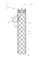
- FIG. 1 is a perspective view showing the external configuration of a stent 10 according to a first embodiment
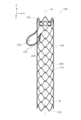
- FIG. 1 is an explanatory diagram showing a planar configuration of a stent 10 according to a first embodiment.
- FIG. 1 is a development view of the main body 100 in the circumferential direction D1.
- FIG. 1 is an explanatory diagram showing a method for weaving the main body 100.
- FIG. 1 is an explanatory diagram showing a method for weaving the main body 100.
- FIG. 1 is an explanatory diagram showing an example of a method of using the stent 10 according to the first embodiment.
- FIG. 13 is an explanatory diagram showing the external configuration of a stent 10a according to a second embodiment.
- FIG. 13 is an explanatory diagram showing the external configuration of a stent 10b according to a third embodiment.
- FIG. 13 is an explanatory diagram showing the external configuration of a stent 10c according to a fourth embodiment.
- FIG. 1 is a perspective view showing the external configuration of a stent 10 in the first embodiment
- Fig. 2 is an explanatory diagram showing the planar configuration of the stent 10 in the first embodiment
- Fig. 1 and Fig. 2 show X, Y and Z axes which are orthogonal to each other.
- the positive side of the Z axis may be referred to as the upper side
- the negative side of the Z axis may be referred to as the lower side.
- Fig. 1 shows a state in which the central axis Ax of the stent 10 (of a tubular portion 110 described later) is parallel to the Z axis, but the stent 10 is configured to be bendable as a whole.
- the stent 10 is a medical device that is placed at the location of a stenosis or at a position that bypasses the stenosis to secure the lumen when a stenosis occurs in an internal body lumen (digestive organs such as the bile duct, gallbladder, pancreas, esophagus, duodenum, small intestine, large intestine, blood vessels, ureters, trachea, etc.).
- the stent 10 is a self-expanding stent that elastically contracts radially when a compressive force is applied and expands radially when the compressive force is released.
- Figures 1 and 2 show the state of the stent 10 when expanded.
- the stent 10 of this embodiment is a so-called covered stent, and includes a main body portion 100 and a cover portion 200.
- the cover portion 200 is shown by a dashed line in FIG. 1, and is omitted from FIG. 2.
- the cover portion 200 is formed from a resin such as polyurethane or silicone, and covers at least a portion of the main body portion 100. In this embodiment, the cover portion 200 covers substantially the entire main body portion 100.
- the main body 100 is the part that constitutes the framework of the stent 10, and is formed by weaving wires W.
- the wires W are made of a superelastic alloy, for example, a nickel-titanium (Ni-Ti) alloy.
- the wires W may be made of other metals, such as stainless steel, tantalum, titanium, cobalt-chromium alloys, magnesium alloys, etc., or may be made of resins, such as polyolefins, polyesters, fluororesins, etc.
- the diameter of the wires W is, for example, about 0.05 mm to 0.5 mm.
- the circumferential direction D1 means a circumferential direction centered on the central axis Ax of the tubular portion 110 of the main body 100, as shown in FIG. 2.
- the main body 100 is woven in a so-called hook weave, and cells CE, which are approximately diamond-shaped holes surrounded by wires W, are regularly arranged.
- the main body 100 has a plurality of intersections 102 where the wires W cross each other without entangling, and a plurality of entanglement portions 101 where an upwardly convex, approximately V-shaped portion of the wire W and a downwardly convex, approximately V-shaped portion of the wire W cross each other in a hook shape and entangle each other.
- the upwardly convex portion of the wire W and the downwardly convex portion of the wire W are connected to each other so as to be movable relative to each other, although they cannot be separated. Therefore, the main body 100 can be curved as a whole, can maintain the curved state, and can be easily placed in a curved biological lumen.
- the main body 100 has a tubular portion 110, a locking portion 120, and a protruding portion 130.
- the tubular portion 110, the locking portion 120, and the protruding portion 130 that constitute the main body 100 are continuously formed by weaving a single wire W.
- the tubular portion 110 is a portion that expands in diameter to become approximately cylindrical when the stent 10 is expanded.
- the radius of the tubular portion 110 when the stent 10 is expanded is, for example, about 2 mm to 40 mm, and the length along the central axis Ax of the tubular portion 110 is, for example, about 20 mm to 200 mm.
- the radius of the tubular portion 110 is appropriately determined depending on the type, size, position, etc. of the internal lumen in which the stent 10 is to be placed.
- the protrusion 130 is a generally V-shaped portion formed by a portion of the wire W, and is a portion that protrudes upward from the upper end of the tubular portion 110, or a portion that protrudes downward from the lower end of the tubular portion 110.
- the protrusion 130 is generally parallel to the central axis Ax of the tubular portion 110.
- six upwardly convex protrusions 130 are arranged continuously in a row in the circumferential direction D1 at the upper end of the tubular portion 110, and six downwardly convex protrusions 130 are arranged continuously in a row in the circumferential direction D1 at the lower end of the tubular portion 110.
- the locking portion 120 is a portion that protrudes from the tubular portion 110 toward the outer periphery when the stent 10 is expanded.
- two locking portions 120 are arranged discretely and evenly spaced side by side in the circumferential direction D1 near the upper end of the tubular portion 110 (slightly below the upper end).
- the two locking portions 120 are substantially identical in shape and size. Due to the presence of the locking portions 120, when the stent 10 is expanded, the maximum radius of the main body portion 100 (i.e., the distance L3 from the central axis Ax of the tubular portion 110 to the outermost point Pt of the locking portion 120) becomes larger than the radius of the tubular portion 110.
- the distance L3 is, for example, 4 mm or more and 50 mm or less.
- the locking portion 120 is formed by a portion of the wire W that constitutes the entangled portion 101. More specifically, as shown in FIG. 3, the locking portion 120 is a portion of one of the wires W that constitutes the entangled portion 101 (such as the specific portion SP shown virtually by the dashed line in FIG. 3, which is a portion that is approximately straight in the other entangled portion 101) that has been given a large curved slack to give it an approximately fan-shaped shape.
- the locking portion 120 is configured so that the wires W that make up the locking portion 120 are located in the same imaginary plane.
- the wires W that make up the locking portion 120 are located in the same imaginary plane does not necessarily mean that the wires W that make up the locking portion 120 are located strictly in the same imaginary plane, but also means that the wires W that make up the locking portion 120 are substantially located in the same imaginary plane, specifically, the distance from any point on the wires W that make up the locking portion 120 to one imaginary plane is 2 mm or less.
- the locking portion 120 is configured to extend obliquely downward from the connection portion with the tubular portion 110 when the stent 10 is expanded.
- the inclination of the locking portion 120 when the stent 10 is expanded is, for example, 20 degrees or more and 70 degrees or less, and more specifically, for example, 30 degrees or more and 60 degrees or less.
- the amount of deformation of the locking portion 120 can be reduced when the stent 10 is reduced in diameter and stored in a storage device (sheath) that constitutes the delivery system, and the load on the inner wall of the storage device caused by the locking portion 120 can be reduced.
- the locking portion 120 is generally fan-shaped as a whole when viewed in the direction of the central axis Ax of the tubular portion 110. That is, the locking portion 120 is shaped so that its width increases with distance from the connection portion with the tubular portion 110. Therefore, the width L0 of the connection portion with the tubular portion 110 in the locking portion 120 is smaller than the width L1 of the other portions.
- the maximum width L1 of the locking portion 120 is greater than the protruding length L2 of the locking portion 120, but is not limited to this. For example, it is sufficient to satisfy the relationship L1 ⁇ 2/3L2.
- the width of the locking portion 120 means the width along the circumferential direction D1
- the protruding length of the locking portion 120 means the protruding length along the virtual plane described above.
- the locking portion 120 is curved along its entire length and does not have any broken portions.
- a cover part 200 is disposed over the entire area 122 surrounded by the wire W that constitutes the locking part 120.
- A-2. Manufacturing method of the stent 10 Next, an example of a method for manufacturing the stent 10 of this embodiment will be described. First, the main body 100 is manufactured by hook knitting the wire W. The method for manufacturing a stent by hook knitting is publicly known, for example, as described in Japanese Patent No. 3708923, but will be briefly described below.
- FIGS 4 and 5 are explanatory diagrams showing the weaving method of the main body 100.
- Each column of Figures 4 and 5 shows, in the form of an exploded view, the procedure for producing the main body 100 by weaving the wire W using a jig JG having multiple pins PN erected on the outer circumferential surface of a cylindrical member.
- the distance between two diagonally adjacent pins PN on the jig JG is referred to as the diagonal distance LP.
- an end of the wire W is fixed to a pin PN at a predetermined position of the jig JG to set the starting point ST, and the wire W is hung in a zigzag pattern from the starting point ST between the pins PN. More specifically, the wire W is extended diagonally to the upper left from the starting point ST to hang it on the upper side of the pin PN, and then the wire W is extended diagonally to the lower left by 1 ⁇ LP to hang it on the lower side of the pin PN, and the wire W is extended diagonally to the upper left by 2 ⁇ LP to hang it on the upper side of the pin PN. This operation is repeated until the wire W reaches a position corresponding to the upper end of the cylindrical portion 110.
- the wire W is hung between the pins PN in a zigzag pattern so that six upwardly convex V-shaped portions (protrusions 130) are formed from the position corresponding to the upper end of the cylindrical portion 110. More specifically, the six protrusions 130 are formed by extending the wire W diagonally to the upper left by 1 ⁇ LP and hanging it on the upper side of the pin PN, and then extending the wire W diagonally to the lower left by 1 ⁇ LP and hanging it on the lower side of the pin PN. At this time, at the position of the pin PN where the wire W is already wound, the wires W cross each other in a hook shape to form the entangled portion 101.
- the wire W is hung between the pins PN in a zigzag pattern so that four downwardly convex V-shaped portions are formed. More specifically, the operation of extending the wire W diagonally downward and left by 1xLP to hang it on the underside of the pin PN, and the operation of extending the wire W diagonally upward and left by 1xLP to hang it on the upper side of the pin PN are repeated four times. After that, the wire W is extended diagonally downward and left by 2xLP.
- Section D of FIG. 5 shows the same operations as in section C of FIG. 4 are repeated until the wire W reaches a position corresponding to the lower end of the tubular portion 110.
- the locking portion 120 before processing is formed. More specifically, at the position where the locking portion 120 is to be formed, the portion of the wire W that constitutes the entangled portion 101 is given slack, and the wire W is hung on the pin PN so as to form a roughly fan-shaped shape.
- Section E of FIG. 5 shows the state where the wire W reaches a position corresponding to the lower end of the tubular portion 110 after two unprocessed locking portions 120 have been formed.
- the wire W is hung between the pins PN in a zigzag pattern so as to form six downwardly convex V-shaped portions (protrusions 130). That is, the wire W is extended diagonally left and down by 1 ⁇ LP to hang it on the underside of the pin PN, and then extended diagonally left and up by 1 ⁇ LP to hang it on the upper side of the pin PN to form the protrusions 130.
- the wire W is extended to the starting point ST, and both ends of the wire W are connected at the starting point ST by forming the crimped portion 114, for example, by crimping.
- the unprocessed locking portion 120 is fixed in a raised position so that it protrudes from the cylindrical portion 110 to the outer periphery, and a heat treatment for shape memory (for example, at 350-600°C for 5-30 minutes) is performed. This forms the locking portion 120 that protrudes from the cylindrical portion 110 to the outer periphery when expanded.
- a heat treatment for shape memory for example, at 350-600°C for 5-30 minutes
- the cover portion 200 is formed at a predetermined location on the main body portion 100. The above steps complete the manufacturing of the stent 10 of this embodiment.
- FIG. 6 is an explanatory diagram showing an example of a method of using the stent 10 of the first embodiment. Note that in Fig. 6, some of the wires W are omitted from the illustration.
- the stent 10 is mounted on the delivery system in a contracted state.
- the engagement portions 120 are folded so as not to protrude from the tubular portion 110 to the outer periphery.
- the delivery system transports the stent 10 to the placement position (the position of the stenosis or a position that bypasses the stenosis) in the biological lumen 20 shown in FIG. 6, and the stent 10 is released from the delivery system at the placement position.
- the stent 10 is expanded due to its self-expanding properties.
- each engagement portion 120 protrudes from the tubular portion 110 to the outer periphery. Therefore, as shown in column A of FIG.
- the engagement portions 120 come into contact with the body wall 21 of the biological lumen 20 and function as anchors, suppressing the displacement (migration) of the stent 10.
- the engaging portion 120 is generally fan-shaped as a whole when viewed in the direction of the central axis Ax of the tubular portion 110, so that a wide area of the engaging portion 120 comes into contact with the body wall 21, which reduces stress concentration on the body wall 21 and suppresses bleeding and perforation in the body wall 21.
- the locking portion 120 is oriented so as to extend diagonally downward from the connection portion with the tubular portion 110. Therefore, as shown in column B of FIG. 6, when a downward force acts on the stent 10, the locking portion 120 changes angle with the connection portion with the tubular portion 110 as a fulcrum, and the inclination with respect to the tubular portion 110 increases. As a result, the outer diameter of the stent 10 becomes even larger, the anchor function of the locking portion 120 increases, and the positional displacement of the stent 10 is more effectively suppressed.
- the narrower width of the connection portion of the engaging portion 120 makes it more likely to flip upward. This reduces the anchor of the engaging portion 120. As a result, the stent 10 can be easily removed.
- the stent 10 of this embodiment includes a main body portion 100.
- the main body portion 100 is formed by weaving wires W, and has a plurality of entangled portions 101 in which the wires W cross each other in a hook shape and entangle with each other.
- the main body portion 100 has a tubular portion 110 and an engaging portion 120.
- the engaging portion 120 is formed by the wires W that constitute the entangled portion 101, and protrudes outward from the tubular portion 110 when the stent 10 is expanded.
- the main body 100 has the locking portion 120 that protrudes from the tubular portion 110 to the outer periphery when the stent 10 is expanded, and the anchor effect of the locking portion 120 can suppress the positional shift of the stent 10 after placement.
- the locking portion 120 is formed from the wire W that constitutes the entanglement portion 101, it is possible to suppress a decrease in strength and durability of the stent 10 caused by the provision of the locking portion 120, compared to a conventional configuration in which the locking portion is provided by deliberately not entangling the wires W at some of the multiple entanglement formation positions.
- the tubular portion 110 and the locking portion 120 that constitute the main body 100 are continuously formed by weaving a single wire W, so no joining member is required to join the tubular portion 110 and the locking portion 120, and the diameter of the stent 10 can be reduced when it is contracted.
- the engaging portion 120 is configured so that the wire W constituting the engaging portion 120 is located in the same imaginary plane. Therefore, according to the stent 10 of this embodiment, it is possible to reduce the concentration of stress on the body wall 21 caused by the engaging portion 120, and to suppress the occurrence of bleeding or perforation in the body wall 21.
- the main body 100 has a plurality of locking portions 120 evenly arranged along the circumferential direction D1 of the tubular portion 110. Therefore, according to the stent 10 of this embodiment, the stress concentration on the body wall 21 caused by the locking portions 120 can be effectively alleviated, and the occurrence of bleeding or perforation in the body wall 21 can be effectively suppressed.
- the engaging portion 120 has a shape in which the width L0 of the connection portion with the tubular portion 110 is smaller than the width L1 of the other portions. Therefore, according to the stent 10 of this embodiment, a wide range of the engaging portion 120 comes into contact with the body wall 21, and the stress concentration on the body wall 21 by the engaging portion 120 can be effectively alleviated, and the occurrence of bleeding or perforation in the body wall 21 can be effectively suppressed. Furthermore, if the stent 10 becomes blocked again, pulling on the end of the stent 10 makes the engaging portion 120 more likely to invert because the width of the connection portion of the engaging portion 120 is small, and as a result, it becomes easier to remove.
- the stent 10 of this embodiment further includes a resin cover portion 200 that covers at least a portion of the main body portion 100.
- the cover portion 200 is also disposed in the region 122 surrounded by the wire W that constitutes the engaging portion 120. Therefore, according to the stent 10 of this embodiment, the stress concentration on the body wall 21 caused by the engaging portion 120 can be more effectively alleviated, and the occurrence of bleeding and perforation in the body wall 21 can be more effectively suppressed.
- the cover portion 200 can prevent tumors, granulation tissue, etc. from entering the engaging portion 120, making removal easy.
- Second embodiment: 7 is an explanatory diagram showing the external configuration of the stent 10a in the second embodiment.
- the same configurations as those of the stent 10 in the first embodiment described above are denoted by the same reference numerals and the description thereof will be omitted as appropriate.
- the second embodiment of the stent 10a differs from the first embodiment of the stent 10 in the configuration of the engagement portion 120.
- the engagement portion 120 is generally spoon-shaped as a whole when viewed in the direction of the central axis Ax of the tubular portion 110. That is, the engagement portion 120 is shaped so that its width becomes wider as it moves away from the connection portion with the tubular portion 110, and then becomes narrower as it moves further away from the connection portion with the tubular portion 110.
- the width L0 of the connection portion of the engagement portion 120 with the tubular portion 110 is smaller than the width L1 of the other portions.
- the maximum width L1 of the engagement portion 120 is smaller than the protruding length L2 of the engagement portion 120.
- a stent 10a having such a configuration can be produced by the manufacturing method of the stent 10 of the first embodiment described above (see column D in Figure 5) by giving slack to the portion of the wire W that constitutes the entangled portion 101 and hanging it on the pin PN so that it is roughly spoon-shaped.
- the main body 100 has an engaging portion 120 formed by the wire W that constitutes the entanglement portion 101, so that the engaging portion 120 can suppress the stent 10a from shifting out of position after placement, while suppressing the decrease in strength and durability of the stent 10a caused by the provision of the engaging portion 120.
- Third embodiment: 8 is an explanatory diagram showing the external configuration of the stent 10b in the third embodiment.
- the same configurations as those of the stent 10a in the second embodiment described above are denoted by the same reference numerals and the description thereof will be omitted as appropriate.
- the stent 10b of the third embodiment differs from the stent 10a of the second embodiment in the configuration of the locking portion 120. Specifically, in the stent 10b of the third embodiment, the locking portion 120 is formed at two positions in the tubular portion 110 as in the second embodiment, but the locking portion 120 is formed double at each position. That is, the main body portion 100 of the stent 10 has multiple locking portions 120 connected to the same position in the tubular portion 110. In the stent 10b of the third embodiment, the circumferential lengths of the wires W of the multiple locking portions 120 connected to the same position in the tubular portion 110 are approximately the same.
- the stent 10b of this configuration can be manufactured by providing slack to the portion of the wire W that constitutes the entanglement portion 101 in the manufacturing method of the stent 10a of the second embodiment described above, and hanging it on the pin PN so as to form a double approximately spoon shape.
- the main body 100 has an engaging portion 120 formed by the wire W that constitutes the entanglement portion 101, so that the engaging portion 120 can suppress the stent 10b from shifting out of position after placement, while suppressing the decrease in strength and durability of the stent 10b caused by providing the engaging portion 120.
- the main body 100 of the stent 10b has multiple locking portions 120 connected to the same position on the tubular portion 110, so that the anchor effect of the locking portions 120 can be increased, and displacement of the stent 10b after placement can be effectively suppressed.
- Fourth embodiment: 9 is an explanatory diagram showing the external configuration of the stent 10c in the fourth embodiment.
- the same configurations as those of the stent 10b in the third embodiment described above are denoted by the same reference numerals and the description thereof will be omitted as appropriate.
- the stent 10c of the fourth embodiment differs from the stent 10b of the third embodiment in the configuration of the locking portion 120.
- the main body 100 of the stent 10c has a plurality (two) locking portions 120 connected to the same position in the tubular portion 110, but the circumferential lengths of the wires W constituting each of these multiple locking portions 120 are different from each other. That is, one locking portion 120 is disposed in an area 122 surrounded by the wires W constituting the other locking portion 120.
- the wires W constituting each of the two locking portions 120 connected to the same position in the tubular portion 110 are located in the same imaginary plane.
- the stent 10 having such a configuration can be manufactured by the manufacturing method of the stent 10b of the third embodiment described above, by giving slack to the portion of the wire W constituting the entanglement portion 101 and hanging it on the pins PN so that it has a double approximately spoon shape of different sizes.
- the main body 100 has the locking portion 120 formed by the wire W that constitutes the entanglement portion 101, so that the locking portion 120 can suppress the stent 10c from shifting out of position after placement, while suppressing the decrease in strength and durability of the stent 10c caused by the provision of the locking portion 120.
- the main body 100 of the stent 10c has multiple locking portions 120 connected to the same position in the tubular portion 110, so that the anchor effect of the locking portion 120 can be increased and the stent 10c can be effectively suppressed from shifting out of position after placement.
- the circumferential lengths of the wires W constituting each of the multiple locking portions 120 connected to the same position on the tubular portion 110 are different from each other, so that the cover portion 200 can be easily and reliably formed in the region 122 surrounded by the wires W constituting the locking portions 120. Therefore, for example, it is possible to realize a thin cover portion 200 formed in the region 122.
- the configuration of the stent 10 in the above embodiment is merely an example, and various modifications are possible.
- the shape of the locking portion 120 is not limited to an approximately fan shape or an approximately spoon shape, and any shape can be adopted.
- the wires W constituting the locking portion 120 do not have to be located in the same imaginary plane.
- the positions and number of the locking portions 120 formed in the tubular portion 110 can be changed arbitrarily.
- the number of locking portions 120 formed in the same position in the tubular portion 110 can be changed arbitrarily.
- the main body portion 100 does not have to have a protrusion 130.
- the manufacturing method of the stent 10 in the above embodiment is merely one example and can be modified in various ways.
- the main body 100 when the main body 100 is made by hook knitting, six V-shaped portions are knitted in the circumferential direction D1, but the number of V-shaped portions lined up in the circumferential direction D1 may be five or less, or seven or more.
- the technology disclosed in this specification is not limited to stents made by hook knitting, but can be similarly applied to stents made by other knitting methods (e.g., cross knitting).
- the knitting method of the main body 100 does not need to be hook knitting throughout, as long as it includes hook knitting in part.
- Stent 20 Stent 20: Biological lumen 21: Body wall 100: Main body 101: Intertwining part 102: Intersection 110: Cylindrical part 114: Fastening part 120: Locking part 122: Area 130: Protrusion 200: Cover part Ax: Central axis CE: Cell JG: Jig PN: Pin W: Wire
Landscapes
- Health & Medical Sciences (AREA)
- Engineering & Computer Science (AREA)
- Biomedical Technology (AREA)
- Heart & Thoracic Surgery (AREA)
- Oral & Maxillofacial Surgery (AREA)
- Transplantation (AREA)
- Cardiology (AREA)
- Vascular Medicine (AREA)
- Life Sciences & Earth Sciences (AREA)
- Animal Behavior & Ethology (AREA)
- General Health & Medical Sciences (AREA)
- Public Health (AREA)
- Veterinary Medicine (AREA)
- Pulmonology (AREA)
- Gastroenterology & Hepatology (AREA)
- Media Introduction/Drainage Providing Device (AREA)
Priority Applications (7)
| Application Number | Priority Date | Filing Date | Title |
|---|---|---|---|
| PCT/JP2023/001432 WO2024154279A1 (ja) | 2023-01-19 | 2023-01-19 | ステント |
| JP2024571522A JPWO2024154279A1 (https=) | 2023-01-19 | 2023-01-19 | |
| EP23917576.3A EP4652967A1 (en) | 2023-01-19 | 2023-03-15 | Stent |
| CN202380091702.2A CN120548156A (zh) | 2023-01-19 | 2023-03-15 | 支架 |
| PCT/JP2023/010059 WO2024154363A1 (ja) | 2023-01-19 | 2023-03-15 | ステント |
| JP2024571600A JPWO2024154363A1 (https=) | 2023-01-19 | 2023-03-15 | |
| US19/272,445 US20250345192A1 (en) | 2023-01-19 | 2025-07-17 | Stent |
Applications Claiming Priority (1)
| Application Number | Priority Date | Filing Date | Title |
|---|---|---|---|
| PCT/JP2023/001432 WO2024154279A1 (ja) | 2023-01-19 | 2023-01-19 | ステント |
Publications (1)
| Publication Number | Publication Date |
|---|---|
| WO2024154279A1 true WO2024154279A1 (ja) | 2024-07-25 |
Family
ID=91955722
Family Applications (2)
| Application Number | Title | Priority Date | Filing Date |
|---|---|---|---|
| PCT/JP2023/001432 Ceased WO2024154279A1 (ja) | 2023-01-19 | 2023-01-19 | ステント |
| PCT/JP2023/010059 Ceased WO2024154363A1 (ja) | 2023-01-19 | 2023-03-15 | ステント |
Family Applications After (1)
| Application Number | Title | Priority Date | Filing Date |
|---|---|---|---|
| PCT/JP2023/010059 Ceased WO2024154363A1 (ja) | 2023-01-19 | 2023-03-15 | ステント |
Country Status (5)
| Country | Link |
|---|---|
| US (1) | US20250345192A1 (https=) |
| EP (1) | EP4652967A1 (https=) |
| JP (2) | JPWO2024154279A1 (https=) |
| CN (1) | CN120548156A (https=) |
| WO (2) | WO2024154279A1 (https=) |
Cited By (1)
| Publication number | Priority date | Publication date | Assignee | Title |
|---|---|---|---|---|
| CN120154455A (zh) * | 2025-03-17 | 2025-06-17 | 广东省人民医院 | 自适应膨胀式金属支架、医疗器械及金属支架加工方法 |
Citations (6)
| Publication number | Priority date | Publication date | Assignee | Title |
|---|---|---|---|---|
| JP2005211293A (ja) * | 2004-01-29 | 2005-08-11 | Piolax Medical Device:Kk | 管状器官の治療具 |
| JP2019063522A (ja) * | 2017-09-29 | 2019-04-25 | 株式会社ジェイ・エム・エス | ステント |
| JP2019531828A (ja) * | 2016-10-24 | 2019-11-07 | エヌヴィーティー アーゲー | 患者の心臓内または心臓血管内に埋め込むための腔内人工血管 |
| WO2020049734A1 (ja) * | 2018-09-07 | 2020-03-12 | オリンパス株式会社 | ステント |
| WO2020194506A1 (ja) * | 2019-03-26 | 2020-10-01 | オリンパス株式会社 | ステント |
| JP2021500181A (ja) * | 2017-10-25 | 2021-01-07 | ボストン サイエンティフィック サイムド,インコーポレイテッドBoston Scientific Scimed,Inc. | 非外傷性スペーサを備えたステント |
Family Cites Families (6)
| Publication number | Priority date | Publication date | Assignee | Title |
|---|---|---|---|---|
| KR100457630B1 (ko) | 2001-04-04 | 2004-11-18 | (주) 태웅메디칼 | 형상기억합금을 이용한 가변상태 유지형 확장기구의제조방법과 이에 의해 제조된 확장기구 |
| JP4073268B2 (ja) * | 2002-07-24 | 2008-04-09 | 株式会社パイオラックスメディカルデバイス | ステント及びステントグラフト |
| KR101382524B1 (ko) * | 2012-02-27 | 2014-04-07 | 국립암센터 | 돌출형 부분이중구조 스텐트 |
| JP6045036B2 (ja) * | 2014-01-28 | 2016-12-14 | 日本ライフライン株式会社 | ステント |
| JP7085010B2 (ja) * | 2018-09-13 | 2022-06-15 | オリンパス株式会社 | ステント |
| JP7484890B2 (ja) * | 2019-03-28 | 2024-05-16 | 株式会社ジェイ・エム・エス | 合成樹脂ステント及びステントデリバリーシステム |
-
2023
- 2023-01-19 WO PCT/JP2023/001432 patent/WO2024154279A1/ja not_active Ceased
- 2023-01-19 JP JP2024571522A patent/JPWO2024154279A1/ja active Pending
- 2023-03-15 WO PCT/JP2023/010059 patent/WO2024154363A1/ja not_active Ceased
- 2023-03-15 EP EP23917576.3A patent/EP4652967A1/en active Pending
- 2023-03-15 CN CN202380091702.2A patent/CN120548156A/zh active Pending
- 2023-03-15 JP JP2024571600A patent/JPWO2024154363A1/ja active Pending
-
2025
- 2025-07-17 US US19/272,445 patent/US20250345192A1/en active Pending
Patent Citations (6)
| Publication number | Priority date | Publication date | Assignee | Title |
|---|---|---|---|---|
| JP2005211293A (ja) * | 2004-01-29 | 2005-08-11 | Piolax Medical Device:Kk | 管状器官の治療具 |
| JP2019531828A (ja) * | 2016-10-24 | 2019-11-07 | エヌヴィーティー アーゲー | 患者の心臓内または心臓血管内に埋め込むための腔内人工血管 |
| JP2019063522A (ja) * | 2017-09-29 | 2019-04-25 | 株式会社ジェイ・エム・エス | ステント |
| JP2021500181A (ja) * | 2017-10-25 | 2021-01-07 | ボストン サイエンティフィック サイムド,インコーポレイテッドBoston Scientific Scimed,Inc. | 非外傷性スペーサを備えたステント |
| WO2020049734A1 (ja) * | 2018-09-07 | 2020-03-12 | オリンパス株式会社 | ステント |
| WO2020194506A1 (ja) * | 2019-03-26 | 2020-10-01 | オリンパス株式会社 | ステント |
Cited By (1)
| Publication number | Priority date | Publication date | Assignee | Title |
|---|---|---|---|---|
| CN120154455A (zh) * | 2025-03-17 | 2025-06-17 | 广东省人民医院 | 自适应膨胀式金属支架、医疗器械及金属支架加工方法 |
Also Published As
| Publication number | Publication date |
|---|---|
| US20250345192A1 (en) | 2025-11-13 |
| WO2024154363A1 (ja) | 2024-07-25 |
| CN120548156A (zh) | 2025-08-26 |
| EP4652967A1 (en) | 2025-11-26 |
| JPWO2024154279A1 (https=) | 2024-07-25 |
| JPWO2024154363A1 (https=) | 2024-07-25 |
Similar Documents
| Publication | Publication Date | Title |
|---|---|---|
| US11497636B2 (en) | Vascular stent | |
| JP4451421B2 (ja) | 自己拡張式形状記憶合金ステント及びその製造方法 | |
| EP3284444B1 (en) | Method for manufacturing stent | |
| EP3369400B1 (en) | Lumen woven support | |
| JP6622914B2 (ja) | ステント | |
| EP3254643B1 (en) | Linking stent and production method for same | |
| JP2006506201A (ja) | メッシュ状構造を有した医療用インプラントの製造方法ならびにこの製造方法によって得られたインプラント | |
| JP7075493B2 (ja) | ステント | |
| EP1903984A1 (en) | Stent and method for manufacturing the same | |
| JP2010521217A (ja) | 内腔拡張用ステント | |
| KR102428729B1 (ko) | 스텐트 및 그 제조방법 | |
| JP7484890B2 (ja) | 合成樹脂ステント及びステントデリバリーシステム | |
| WO2024154279A1 (ja) | ステント | |
| JP2008200293A (ja) | ステント及びそれを用いた管状器官の治療具 | |
| JP2011504407A (ja) | 円筒形ステント | |
| KR20170117783A (ko) | 스텐트 제조방법 | |
| US20100016951A1 (en) | Stent | |
| WO2025074529A1 (ja) | ステント | |
| JP7252671B2 (ja) | ステントおよびその製作方法 | |
| EP3949915B1 (en) | Synthetic resin stent | |
| US20220273473A1 (en) | Stent device having looped interlocking regions and non-looped interlocking regions | |
| JP2026004852A (ja) | ステント | |
| WO2023160510A1 (zh) | 医用支架及医用支架系统 | |
| CN119302784A (zh) | 腔内植入物、缝合方法及血管塞系统 | |
| CN115889619A (zh) | 一种胆道支架制造夹具及胆道支架制造方法 |
Legal Events
| Date | Code | Title | Description |
|---|---|---|---|
| 121 | Ep: the epo has been informed by wipo that ep was designated in this application |
Ref document number: 23917492 Country of ref document: EP Kind code of ref document: A1 |
|
| WWE | Wipo information: entry into national phase |
Ref document number: 2024571522 Country of ref document: JP |
|
| NENP | Non-entry into the national phase |
Ref country code: DE |
|
| 122 | Ep: pct application non-entry in european phase |
Ref document number: 23917492 Country of ref document: EP Kind code of ref document: A1 |