WO2024154240A1 - 熱交換器及び空気調和機 - Google Patents
熱交換器及び空気調和機 Download PDFInfo
- Publication number
- WO2024154240A1 WO2024154240A1 PCT/JP2023/001258 JP2023001258W WO2024154240A1 WO 2024154240 A1 WO2024154240 A1 WO 2024154240A1 JP 2023001258 W JP2023001258 W JP 2023001258W WO 2024154240 A1 WO2024154240 A1 WO 2024154240A1
- Authority
- WO
- WIPO (PCT)
- Prior art keywords
- wire
- heat transfer
- heat exchanger
- transfer tube
- fin
- Prior art date
- Legal status (The legal status is an assumption and is not a legal conclusion. Google has not performed a legal analysis and makes no representation as to the accuracy of the status listed.)
- Ceased
Links
Images










Classifications
-
- F—MECHANICAL ENGINEERING; LIGHTING; HEATING; WEAPONS; BLASTING
- F28—HEAT EXCHANGE IN GENERAL
- F28F—DETAILS OF HEAT-EXCHANGE AND HEAT-TRANSFER APPARATUS, OF GENERAL APPLICATION
- F28F1/00—Tubular elements; Assemblies of tubular elements
- F28F1/10—Tubular elements and assemblies thereof with means for increasing heat-transfer area, e.g. with fins, with projections, with recesses
- F28F1/12—Tubular elements and assemblies thereof with means for increasing heat-transfer area, e.g. with fins, with projections, with recesses the means being only outside the tubular element
-
- F—MECHANICAL ENGINEERING; LIGHTING; HEATING; WEAPONS; BLASTING
- F28—HEAT EXCHANGE IN GENERAL
- F28F—DETAILS OF HEAT-EXCHANGE AND HEAT-TRANSFER APPARATUS, OF GENERAL APPLICATION
- F28F1/00—Tubular elements; Assemblies of tubular elements
- F28F1/10—Tubular elements and assemblies thereof with means for increasing heat-transfer area, e.g. with fins, with projections, with recesses
- F28F1/12—Tubular elements and assemblies thereof with means for increasing heat-transfer area, e.g. with fins, with projections, with recesses the means being only outside the tubular element
- F28F1/34—Tubular elements and assemblies thereof with means for increasing heat-transfer area, e.g. with fins, with projections, with recesses the means being only outside the tubular element and extending obliquely
- F28F1/36—Tubular elements and assemblies thereof with means for increasing heat-transfer area, e.g. with fins, with projections, with recesses the means being only outside the tubular element and extending obliquely the means being helically wound fins or wire spirals
-
- H—ELECTRICITY
- H10—SEMICONDUCTOR DEVICES; ELECTRIC SOLID-STATE DEVICES NOT OTHERWISE PROVIDED FOR
- H10W—GENERIC PACKAGES, INTERCONNECTIONS, CONNECTORS OR OTHER CONSTRUCTIONAL DETAILS OF DEVICES COVERED BY CLASS H10
- H10W40/00—Arrangements for thermal protection or thermal control
-
- H—ELECTRICITY
- H10—SEMICONDUCTOR DEVICES; ELECTRIC SOLID-STATE DEVICES NOT OTHERWISE PROVIDED FOR
- H10W—GENERIC PACKAGES, INTERCONNECTIONS, CONNECTORS OR OTHER CONSTRUCTIONAL DETAILS OF DEVICES COVERED BY CLASS H10
- H10W40/00—Arrangements for thermal protection or thermal control
- H10W40/40—Arrangements for thermal protection or thermal control involving heat exchange by flowing fluids
- H10W40/43—Arrangements for thermal protection or thermal control involving heat exchange by flowing fluids by flowing gases, e.g. forced air cooling
-
- H—ELECTRICITY
- H10—SEMICONDUCTOR DEVICES; ELECTRIC SOLID-STATE DEVICES NOT OTHERWISE PROVIDED FOR
- H10W—GENERIC PACKAGES, INTERCONNECTIONS, CONNECTORS OR OTHER CONSTRUCTIONAL DETAILS OF DEVICES COVERED BY CLASS H10
- H10W40/00—Arrangements for thermal protection or thermal control
- H10W40/70—Fillings or auxiliary members in containers or in encapsulations for thermal protection or control
- H10W40/73—Fillings or auxiliary members in containers or in encapsulations for thermal protection or control for cooling by change of state
Definitions
- This disclosure relates to a heat exchanger and an air conditioner, and in particular to a heat exchanger and an air conditioner having wire fins.
- Patent Document 1 proposes a wire fin type flat tube heat exchanger in which wire fins are wrapped around flat tubes, and discloses that the method of wrapping the wire fins around the flat tubes is to form the wire fins and then wrap them around the flat tubes. There are also heat exchangers in which the wire fins are woven into the tubes in a net-like pattern.
- the periodic spacing direction of the waves of the wavy wire fins is arranged perpendicular to the step direction of the flat tubes.
- the periodic spacing direction of the waves of the wavy wire fins is arranged parallel to the refrigerant flow path direction of the flat tubes.
- the purpose of this disclosure is to provide a heat exchanger and an air conditioner that improve the heat transfer performance between the wire fins and the heat transfer tube.
- the heat exchanger comprises heat transfer tubes arranged in a step direction, wire fins having a wavy portion formed in a wave shape by wire and a heat transfer tube joint portion inserted into and joined to the heat transfer tubes, and the periodic interval direction, which is the direction in which the waves of the wire fins advance, is aligned with the step direction of the heat transfer tubes.
- the air conditioner according to the present disclosure further comprises a heat exchanger provided inside a housing and including a heat transfer tube and a wire fin having a wavy portion with a wave-like shape and a heat transfer tube joint portion inserted into and joined to the heat transfer tube, the periodic interval direction being the direction in which the waves of the wire fin advance, being arranged along the step direction of the heat transfer tube, and a blower fan provided inside the housing and blowing air that has been heat exchanged through the heat exchanger to the outside of the housing, the heat exchanger being circular, arc-shaped, or U-shaped, and arranged to surround the blower fan.
- the wire fins and the heat transfer tube are joined so that the periodic spacing direction of the wavy wire fins is aligned with the row direction of the heat transfer tube. This extends the contact length between the heat transfer tube and the wire fins, improving the heat transfer performance between the wire fins and the heat transfer tube.
- FIG. 1 is a perspective view showing a heat exchanger according to a first embodiment
- 3 is a cross-sectional view of a wire fin and a heat transfer tube of the heat exchanger according to the first embodiment.
- FIG. 1 is a cross-sectional view of a heat exchanger according to a first embodiment before assembly.
- FIG. 4 is an image diagram of wire fins of the heat exchanger according to the first embodiment.
- 1 is a schematic diagram of an air conditioner including a heat exchanger according to a first embodiment.
- FIG. 11 is a perspective view showing a heat exchanger according to a second embodiment.
- FIG. 11 is a cross-sectional view showing a first wire fin, a second wire fin, and a heat transfer tube of a heat exchanger according to a second embodiment.
- FIG. 11 is a cross-sectional view of a heat exchanger according to a second embodiment before it is assembled.
- FIG. FIG. 11 is a schematic diagram of a heat exchanger according to a third embodiment.
- FIG. 11 is a partial perspective view of a heat exchanger according to a third embodiment.
- 11 is a schematic diagram of a heat exchanger according to a third embodiment, viewed in the direction of a refrigerant flow path.
- FIG. 11 is a schematic diagram of a heat exchanger according to a third embodiment, viewed in the row direction.
- FIG. FIG. 11 is a perspective view showing a second connecting wire of the heat exchanger according to the third embodiment.
- FIG. 11 is a perspective view showing a third connecting wire of the heat exchanger according to the third embodiment.
- FIG. 11 is a cross-sectional view of a heat exchanger according to a second embodiment before it is assembled.
- FIG. FIG. 11 is a schematic diagram of a heat exchanger according to a third embodiment.
- FIG. 15 is a schematic diagram of the heat exchanger of FIG. 14 as viewed in the row direction.
- FIG. 13 is a schematic diagram of a heat exchanger according to a fourth embodiment.
- FIG. 11 is a side view of a blower fan arranged together with a heat exchanger according to embodiment 4.
- FIG. 13 is a schematic diagram of an air conditioner equipped with a heat exchanger according to a fifth embodiment.
- FIG. 13 is a perspective view of a heat exchanger according to a sixth embodiment.
- 13 is a schematic diagram of a heat exchanger according to a sixth embodiment, viewed in the direction of a refrigerant flow path.
- FIG. FIG. 23 is a schematic diagram of heat exchange according to a modified example of the sixth embodiment.
- Fig. 1 is a perspective view showing a heat exchanger 100 according to embodiment 1.
- Fig. 2 is a cross-sectional view of a wire fin 1 and a heat transfer tube 2 of the heat exchanger 100 according to embodiment 1.
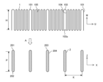
- Fig. 3 is a cross-sectional view of the heat exchanger 100 according to embodiment 1 before being assembled.
- the heat exchanger 100 has wire fins 1 and heat transfer tubes 2.
- the flow direction of the refrigerant in the refrigerant flow passage 600 is the longitudinal direction of the flat tubes that are the heat transfer tubes 2, and is the depth direction of the flat tubes, which is referred to as the refrigerant flow passage direction Y.
- the direction in which the multiple refrigerant flow passages 600 are arranged side by side is the row direction of the flat tubes that are the heat transfer tubes 2, which is referred to as the long axis direction Z.
- the multiple heat transfer tubes 2 are arranged side by side, and the specific direction in which the multiple heat transfer tubes 2 are arranged is the short axis direction of the flat tubes that are the heat transfer tubes 2, which is referred to as the row direction X.
- the direction of the wave period of the wire fin 1, which is the direction in which the waves travel, is referred to as the period interval direction U.
- the direction of the wave amplitude in the wire fin 1 is referred to as the amplitude direction W.
- the direction in which the wire fins 1 are arranged at a predetermined interval is the overlap direction, which is the depth direction and is referred to as the overlap direction V.
- the heat transfer tubes 2 are, for example, flat tubes having a flat cross section. Inside the heat transfer tubes 2, multiple refrigerant flow paths 600 having a predetermined length are formed so as to overlap each other. For example, multiple refrigerant flow paths 600 are arranged side by side in the vertical direction. Note that in FIG. 1, the refrigerant flow paths 600 are only shown in one of the three heat transfer tubes 2, and are not shown in the other two heat transfer tubes 2. Multiple heat transfer tubes 2 are arranged at predetermined intervals in the row direction X.
- the row direction X is, for example, the vertical direction.
- the heat transfer tubes 2 are arranged so that multiple refrigerant flow paths 600, each having a predetermined length, overlap each other, that is, multiple heat transfer tubes 2 are arranged in the long axis direction Z, which is the up-down direction in FIG. 1.
- Multiple heat transfer tubes 2 are arranged at predetermined intervals in the row direction X, which is the short axis direction, which is a predetermined direction. It is desirable for the multiple heat transfer tubes 2 to be arranged at approximately equal intervals.
- the wire fins 1 are fins formed by shaping wires, such as aluminum wires, made of aluminum material, into a wavy shape.
- the wire fins 1 are provided at predetermined intervals in the refrigerant flow path direction Y of the heat transfer tube 2. The intervals between the wire fins 1 may be equal or unequal. A predetermined number of wire fins 1 are provided.
- the wire fin 1 is composed of a fixed portion 101 and a wavy portion 105.
- the fixed portion 101 is a heat transfer tube joint that is joined to the heat transfer tube 2, and has a wire fin arc portion 103 and a wire fin straight portion 104.
- the fixed portion 101 is fixed to the heat transfer tube 2 by line contact.
- the wavy portions 105 are multiple wavy portions formed in the periodic interval direction U.
- the wire fin arc portion 103 is a portion formed in an arc shape at one end side of the fixed portion 101 in the amplitude direction W.
- the other end side of the fixed portion 101 in the amplitude direction W is an opening 103a for inserting the wire fin 1 into the heat transfer tube 2.
- the heat transfer tube 2 has a flattened tube shape having a heat transfer tube arc section 203 and a heat transfer tube straight section 204.
- the heat transfer tube arc section 203 has a first end 201 and a second end 202 in the longitudinal axis direction Z of the heat transfer tube 2.
- the first end 201 and the second end 202 are formed in an arc shape having a radius approximately equal to that of the wire fin arc section 103.
- the fixed portion 101 and the wavy portion 105 which are the heat transfer joints of the wire fin 1, are formed at a predetermined interval in the periodic interval direction U.
- the total amplitude H of the wire fin 1 may be equal to the major axis dimension P, which is the dimension in the major axis direction of the heat transfer tube 2.
- the opening 103a of the wire fin 1 is inserted from one end in the longitudinal direction Z of the heat transfer tube 2, for example, the first end 201, until the wire fin arc portion 103 and the heat transfer tube arc portion 203 come into contact.
- the wire fin arc portion 103 is inserted into the heat transfer tube arc portion 203 from one end in the longitudinal direction Z of the heat transfer tube 2, that is, from the insertion direction A in FIG. 3.
- the wire fin 1 is inserted into the heat transfer tube 2, for example, by press fitting. Instead of inserting by press fitting, the wire fin 1 may be inserted by a close contact molding press in which the heat transfer tube 2 is pressed into close contact with the heat transfer tube 2 using a jig or the like after the heat transfer tube 2 is inserted.
- the wire fin 1 is inserted until the wire fin arc portion 103 of the wire fin 1 comes into contact with the heat transfer tube arc portion 203 of the heat transfer tube 2, and the wire fin straight portion 104 comes into contact with the heat transfer tube straight portion 204 and is thermally joined.
- the wire fin 1 and the heat transfer tube 2 are thermally joined by, for example, brazing or zinc spraying.
- the radius of the wire fin arc section 103 is formed to be approximately equal to the radius of the heat transfer tube arc section 203, so that the wire fin arc section 103 and the heat transfer tube arc section 203 can come into contact with each other through their arc shapes. This improves the contact rate between the wire fin 1 and the heat transfer tube 2, and ensures the contact length, so that the wire fin 1 and the heat transfer tube 2 can be thermally joined with improved thermal conductivity.
- the fixing portion 101 to which the heat transfer tube 2 is joined in the wire fin 1 is inserted while being pressed into the heat transfer tube 2, so that the wire fin straight section 104 can come into linear contact with the heat transfer tube straight section 204 in a straight line. Therefore, the contact length between the wire fin 1 and the heat transfer tube 2 is increased compared to when the wire fin 1 is not pressed in, improving reliability and heat transfer performance.
- the wire fin straight section 104 makes linear contact with the heat transfer tube straight section 204, increasing the contact length, improving reliability, and improving heat transfer performance.
- the wire fin arc section 103 provided on the fixing part 101 of the wire fin 1 is formed in an arc shape so that the arc shape comes into contact with the heat transfer tube arc section 203 of the heat transfer tube 2, increasing the contact length with the heat transfer tube 2.
- the wire fin straight section 104 provided on the fixing part 101 of the wire fin 1 is provided so as to come into contact with the heat transfer tube straight section 204 in a straight line, and the wire fin straight section 104 and the heat transfer tube straight section 204 are thermally joined so as to come into contact in a straight line.
- the wire fin 1 has multiple fixed portions 101 and wavy portions 105 arranged in the periodic spacing direction U, and is arranged so that the periodic spacing direction U is approximately parallel to the row direction X of the heat transfer tubes 2. Therefore, even if there is variation in the spacing K between the heat transfer tubes 2, the wire fin arc portion 103 of the wire fin 1 is inserted into the heat transfer tube arc portion 203 of the heat transfer tube 2 in a press-fit manner, thereby absorbing the variation in the spacing K.
- FIG. 4 is an image diagram of the wire fins 1 of the heat exchanger 100 according to the first embodiment.
- the wire fins 1 before being inserted into the heat transfer tubes 2 and the wire fins 1 inserted into the heat transfer tubes 2 are shown side by side.
- the spacing between adjacent fixing portions 101 is wider than the spacing K, which is the tube pitch between adjacent heat transfer tubes 2.
- the wire fins 1 are formed in a wavy shape, so when the wire fins 1 are inserted into the heat transfer tubes 2, the wavy portions 105 expand and contract according to the spacing K between the adjacent heat transfer tubes 2, and the shape of the wavy portions of the wavy portions 105 changes. This makes it possible to absorb the dimensional variation in the spacing K between the adjacent heat transfer tubes 2.
- the wire fin 1 is inserted by press-fitting from the insertion direction A in FIG. 3 into one end of the heat transfer tube 2 in the longitudinal direction Z, for example, the first end 201. Therefore, even if there is variation in the dimension of the spacing K between adjacent heat transfer tubes 2, the deformation of the wavy portion 105 prevents the wire fin 1 from coming off the heat transfer tube 2 or becoming displaced, improving the ease of assembly of the heat exchanger 100.
- the wire fin 1 is formed by shaping a wire such as an aluminum wire into a wave shape.
- the wire fin 1 is thermally connected to the heat transfer tube 2 so that the wave period interval direction U is parallel to the row direction X of the heat transfer tube 2.
- the length H of the amplitude direction W of the wavy portion 105 of the wire fin 1 is set to be equal to the length P of the row direction Z, which is the long axis direction of the heat transfer tube 2. It is preferable that the length H of the amplitude direction W of the wavy portion 105 of the wire fin 1 is approximately equal to or shorter than the length P of the row direction Z, which is the long axis direction of the heat transfer tube 2. In this way, the wavy portion 105 of the wire fin 1 does not protrude in the row direction Z, which is the long axis direction of the heat transfer tube 2, improving the ease of assembly and reliability of the heat exchanger 100.
- the fixing portion 101 which is the heat transfer tube joint portion of the wire fin 1 configured in this manner, has a wire fin arc portion 103 and two wire fin straight portions 104.
- the wire fin arc portion 103 and the wire fin straight portion 104 are thermally joined in line contact with the heat transfer tube arc portion 203 and the heat transfer tube straight portion 204 of the heat transfer tube 2, respectively. Therefore, the length of line contact of the wire fin 1 with the heat transfer tube 2 is extended, so the contact length is extended, improving the reliability of the joint and also improving the heat exchange efficiency.
- the wire fin 1 is formed in a wavy shape, and the wavy portion 105 of the wire fin 1 is in the periodic spacing direction U and can expand and contract in the direction of the spacing K between the heat transfer tubes 2, so that no problem occurs even if the dimension of the spacing K between the heat transfer tubes 2 varies. Therefore, the wavy portion 105 of the wire fin 1 can absorb the variation in the spacing K between the heat transfer tubes 2. Therefore, the heat transfer tube straight portion 204 of the heat transfer tube 2 and the wire fin straight portion 104 of the wire fin 1 can be thermally joined in a state of intimate contact.
- the wire fin 1 is folded back at the heat transfer tube straight portion 204 of the heat transfer tube 2a that is located at the outermost end in the row direction X among the multiple heat transfer tubes 2, so that multiple wire fins 1 are arranged in the refrigerant flow direction Y with one wire.
- the wire fins 1 of the heat exchanger 100 are folded back at the heat transfer tube straight portion 204 of the heat transfer tube 2a that is located at the outermost end in the row direction X.
- the wire fin 1 has a folded back portion 1a formed at the heat transfer tube straight portion 204 of the heat transfer tube 2a that is located at the outermost end in the row direction X. This improves the productivity of the heat exchanger 100.
- the wire fins 1 are formed in a wavy shape, and in addition to the wire fin arc sections 103, the wire fin straight sections 104 also make line contact with the heat transfer tubes 2. Therefore, the length of line contact between the wire fins 1 and the heat transfer tubes 2 is longer than when the fins and the heat transfer tubes are in contact only at the arc-shaped portions. Furthermore, the wire fins 1 and the heat transfer tubes 2 are combined by selecting the shape of the wire fins 1 and the combination direction, i.e., the joining direction, so that the contact force between the wire fins 1 and the heat transfer tubes 2 is increased, improving the reliability and heat transferability of the joint.
- the wire fins 1 are formed into a wavy shape using wires such as aluminum wires, and are thermally joined to the heat transfer tubes 2 so that the periodic spacing direction U of the wire fins 1 is parallel to the row direction X of the heat transfer tubes 2.
- the wavy portions 105 of the wire fins 1 expand and contract in the periodic spacing direction U, in the direction of the spacing K between adjacent heat transfer tubes 2, and the expansion and contraction of the wavy portions 105 can absorb variations in the spacing K. Therefore, even if the spacing K between adjacent heat transfer tubes 2 varies, it is possible to improve heat transfer without reducing the reliability of the joint.
- FIG. 5 is a schematic diagram of an air conditioner 140 equipped with a heat exchanger 100 according to embodiment 1.
- the air conditioner 140 is configured with the heat exchanger 100 and a blower fan 500 disposed inside a housing 130.
- the housing 130 is, for example, an indoor unit disposed indoors.
- the blower fan 500 blows air that has undergone heat exchange via the heat exchanger 100 into the room or outside.
- the blower fan 500 blows air into the room.
- the heat exchanger 100 is composed of wire fins 1 and heat transfer tubes 2.
- the wire fins 1 are formed into a wavy shape using wire.
- the heat transfer tubes 2 are, for example, flat tubes, and are arranged in the step direction X.
- the wire fins 1 are joined to the heat transfer tubes 2 so that the periodic spacing direction U, which is the direction in which the waves of the wire fins 1 advance, is aligned with the step direction X.
- the periodic spacing direction U of the wire fins 1 is the direction in which the waves advance and the direction of the periodic spacing.
- the heat transfer tubes 2 and the wire fins 1 are connected so that the periodic spacing direction U of the wire fins 1 is parallel to the row direction X of the heat transfer tubes 2. This increases the contact length between the heat transfer tubes 2 and the wire fins 1, improving the heat transfer performance between the wire fins 1 and the heat transfer tubes 2.
- the wire fins 1 are inserted from the row direction Z, which is the long axis direction of the heat transfer tubes 2, and the heat transfer tubes 2 are sandwiched in between. Therefore, even if there is variation in the dimension of the spacing K of the heat transfer tubes 2, the deformation of the wavy portion 105 prevents the wire fins 1 from coming off the heat transfer tubes 2 or from becoming misaligned, improving the ease of assembly of the heat exchanger 100.
- the wire fin 1 also has a wavy portion 105 and a fixed portion 101 which is the heat transfer tube joint, and the heat transfer tube 2 is press-fitted into the fixed portion. Therefore, even if there is variation in the spacing K between adjacent heat transfer tubes 2, the variation in spacing K can be absorbed by the expansion and contraction of the wavy portion 105.
- the heat exchanger 100 can provide an air conditioner 140 with high thermal efficiency.
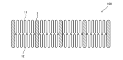
- Fig. 6 is a perspective view showing a heat exchanger 100 according to embodiment 2.
- Fig. 7 is a cross-sectional view showing a first wire fin 11, a second wire fin 12, and a heat transfer tube 2 of the heat exchanger 100 according to embodiment 2.
- the second embodiment differs from the first embodiment in that the wire fin 1 is inserted from one end side of the heat transfer tube 2 in the longitudinal direction Z to extend the line contact length between the wire fin 1 and the heat transfer tube 2 in that the wire fin 1 is sandwiched from both sides in the longitudinal direction Z of the heat transfer tube 2.
- the same reference numerals are used to denote parts common to the first embodiment, and the description is omitted, and the differences from the first embodiment will be mainly described.
- the wire fin 1 is composed of a first wire fin 11 and a second wire fin 12.
- the first wire fin 11 and the second wire fin 12 are formed into a wave shape using wire such as aluminum wire.
- the heat transfer tube 2 is, for example, a flat tube, and is composed of multiple refrigerant flow paths 600 having a predetermined length arranged side by side so as to overlap each other.
- FIG. 4 shows multiple refrigerant flow paths 600 arranged side by side in the vertical direction.
- the refrigerant flow direction of the refrigerant flow passage 600 is the flat tube longitudinal direction or the flat tube depth direction, as in the first embodiment, and is referred to as the refrigerant flow passage direction Y.
- the direction in which the multiple refrigerant flow passages 600 are arranged side by side is referred to as the flat tube long axis direction Z or row direction Z.
- the multiple heat transfer tubes 2 are arranged side by side in a predetermined direction and at predetermined intervals, and the predetermined direction in which the heat transfer tubes 2 are arranged side by side is the flat tube short axis direction and is referred to as the row direction X. It is preferable that the predetermined intervals between the multiple heat transfer tubes 2 are equal.
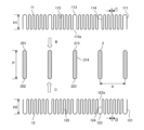
- FIG. 8 is a cross-sectional view of the heat exchanger 100 according to the second embodiment before it is assembled.
- the first wire fin 11 is composed of a fixed portion 111 joined to the heat transfer tube 2 and a wavy portion 115
- the second wire fin 12 is composed of a fixed portion 121 joined to the heat transfer tube 2 and a wavy portion 125.
- the direction of the wave period of the first wire fin 11 and the second wire fin 12, that is, the direction in which the waves advance, is referred to as the period interval direction U, and the direction of the wave amplitude is referred to as the amplitude direction W.
- the total amplitude of the waves of the first wire fin 11 is indicated by H1
- the total amplitude of the waves of the second wire fin 12 is indicated by H2.
- the fixing portion 111 has a wire fin arc portion 113 and two wire fin straight portions 114
- the fixing portion 121 has a wire fin arc portion 123 and two wire fin straight portions 124.
- the first wire fin 11 fits into the heat transfer tube 2 and is fixed to the heat transfer tube 2 by line contact at the fixing portion 111.
- the second wire fin 12 fits into the heat transfer tube 2 and is fixed to the heat transfer tube 2 by line contact at the fixing portion 121.
- the wavy portion 115 and the wavy portion 125 are each formed in a shape in which multiple waves advance along the periodic interval direction U.
- the first wire fin 11 and the second wire fin 12 are each provided at a predetermined interval along the refrigerant flow path direction Y of the heat transfer tube 2.
- the predetermined intervals may be equal or unequal.
- the first wire fins 11 and the second wire fins 12 are each provided in a predetermined number of pieces.
- the numbers of the first wire fins 11 and the second wire fins 12 may be equal or different.
- the direction in which the first wire fins 11 and the second wire fins 12 are provided at a predetermined interval is referred to as the refrigerant flow path direction Y, the overlap direction V, or the overlap depth direction V.
- the fixed portion 111 of the first wire fin 11 has one end in the amplitude direction W of the periodic interval direction U, overlap direction V, and amplitude direction W as a wire fin arc portion 113 formed in an arc shape.
- the other end of the fixed portion 111 has an opening 113a formed for insertion into the heat transfer tube 2.
- the fixed portion 121 of the second wire fin 12 has one end in the amplitude direction W as an opening 123a formed for insertion into the heat transfer tube 2, and the other end as a wire fin arc portion 123 formed in an arc shape.
- the heat transfer tube 2 has a plurality of refrigerant flow paths 600 in the row direction X, the longitudinal depth direction which is the refrigerant flow path direction Y, and the longitudinal axis direction Z.
- the first end 201 and the second end 202 in the longitudinal axis direction Z of the heat transfer tube 2 are formed in an arc shape.
- the first end 201 and the second end 202 in the longitudinal axis direction Z the first end 201 is a heat transfer tube arc section 213 formed in an arc shape having a radius equivalent to that of the wire fin arc section 113.
- the second end 202 is a heat transfer tube arc section 223 formed in an arc shape having a radius equivalent to that of the wire fin arc section 123.
- the fixed portions 111 and wavy portions 115 of the first wire fin 11 are arranged at predetermined intervals such that the periodic spacing direction U is aligned with the row direction X of the heat transfer tube 2.
- the fixed portions 111 and wavy portions 115 of the second wire fin 12 are arranged at predetermined intervals such that the periodic spacing direction U is aligned with the row direction X of the heat transfer tube 2.
- the first wire fin 11 is moved in the insertion direction B in FIG. 8 until the wire fin arc portion 113 of the first wire fin 11 contacts the heat transfer tube arc portion 213, and the first end portion 201 in the longitudinal direction Z of the heat transfer tube 2 is inserted while being pressed in from the opening 113a.
- the second wire fin 12 is moved in the insertion direction C in FIG. 8 until the wire fin arc portion 123 of the second wire fin 12 contacts the heat transfer tube arc portion 223.
- the second end portion 202 in the longitudinal direction Z of the heat transfer tube 2 is inserted while being pressed in from the opening 123a in the insertion direction B.
- the radius of the wire fin arc portion 113 is formed to be approximately equal to the radius of the heat transfer tube arc portion 213, and the wire fin arc portion 113 and the heat transfer tube arc portion 213 can be in contact with each other with approximately the same shape. Therefore, the wire fin arc portion 113 and the heat transfer tube arc portion 213 can be in contact with each other with a high contact rate, and the contact length can be secured to allow thermal bonding.
- the radius of the wire fin arc portion 123 is formed to be approximately equal to the radius of the heat transfer tube arc portion 223, and the wire fin arc portion 123 and the heat transfer tube arc portion 223 can be in contact with each other with approximately the same shape. Therefore, the wire fin arc portion 123 and the heat transfer tube arc portion 223 can be in contact with each other with a high contact rate, and the contact length can be secured to allow thermal bonding.
- the wire fin straight portion 114 can be in linear contact with the heat transfer tube straight portion 214.
- the wire fin straight portion 124 can be in linear contact with the heat transfer tube straight portion 214. Therefore, the contact length between the first wire fin 11 and the second wire fin 12 and the heat transfer tube 2 is longer than when they are not pressed in, improving reliability and heat transfer performance.
- the first wire fin 11 is formed with a wire fin arc section 113 formed in an arc shape so as to be in contact with the heat transfer tube arc section 213 of the heat transfer tube 2 in an arc shape, so that the contact length between the fixing section 111 and the heat transfer tube 2 can be extended. Furthermore, the first wire fin 11 is provided with a wire fin straight section 114 that is in linear contact with the heat transfer tube straight section 214 of the heat transfer tube 2, and the wire fin straight section 114 is thermally joined in linear contact with the heat transfer tube straight section 214.
- the second wire fin 12 is formed with a wire fin arc section 123 formed in an arc shape so as to be in contact with the heat transfer tube arc section 213 of the heat transfer tube 2 in an arc shape, thereby extending the contact length between the fixing section 121 and the heat transfer tube 2. Furthermore, the second wire fin 12 is provided with a wire fin straight section 124 that is in linear contact with the heat transfer tube straight section 214 of the heat transfer tube 2, and the wire fin straight section 124 is thermally joined in linear contact with the heat transfer tube straight section 214.
- the first wire fin 11 and the second wire fin 12 are both arranged such that the periodic spacing direction U is aligned with the row direction X of the heat transfer tube 2.
- the wire fin arc portion 113 of the first wire fin 11 is inserted into the heat transfer tube arc portion 213 of the heat transfer tube 2
- the wire fin arc portion 123 of the second wire fin 12 is inserted into the heat transfer tube arc portion 223 of the heat transfer tube 2. Even if there is variation in the spacing K between adjacent heat transfer tubes 2, the wire fin arc portion 113 of the first wire fin 11 and the wire fin arc portion 123 of the second wire fin 12 are inserted while being pressed in, so that the variation in the spacing K can be absorbed.
- the first wire fin 11 and the second wire fin 12 are inserted while being pressed in from the insertion direction B and the insertion direction C, respectively, along the longitudinal direction Z of the heat transfer tube 2, so that the wavy portions 115 and 125 can be deformed to match the spacing K between the adjacent heat transfer tubes 2. Therefore, even if there is variation in the dimension of the spacing K between the adjacent heat transfer tubes 2, the wavy portions 115 and 125 can be deformed to prevent the first wire fin 11 and the second wire fin 12 from coming off the heat transfer tube 2 or becoming displaced.
- first wire fin 11 and the second wire fin 12 are formed into a wavy shape using wires such as aluminum wires, which improves assembly, and the periodic spacing direction U is thermally joined to the heat transfer tube 2 along the row direction X of the heat transfer tube 2.
- the length H1 in the amplitude direction W of the wavy portion 115 of the first wire fin 11 and the length H2 in the amplitude direction W of the wavy portion 125 of the second wire fin 12 are approximately equal, and H1 ⁇ H2.
- the total length H1 + H2 of the length H1 in the amplitude direction W of the wavy portion 115 of the first wire fin 11 and the length H2 in the amplitude direction W of the wavy portion 125 of the second wire fin 12 are approximately equal to the length L in the longitudinal direction Z, i.e., the row direction Z, of the heat transfer tube 2, and H1 + H2 ⁇ L.
- the total length H1 in the amplitude direction W of the wavy portion 115 of the first wire fin 11 and the length H2 in the amplitude direction W of the wavy portion 125 of the second wire fin 12 should be approximately equal to the longitudinal direction Z of the heat transfer tube 2 or shorter than that.
- the longitudinal direction Z is the length L in the row direction Z.
- the length H1 in the amplitude direction W of the first wire fin 11 and the length H2 in the amplitude direction W of the second wire fin 12 are approximately equal, that is, H1 ⁇ H2, but the length H1 and the length H2 do not have to be equal.
- the length H1 in the amplitude direction W of the first wire fin 11 and the length H2 in the amplitude direction W of the second wire fin 12 may be changed to improve efficiency depending on the air flow direction or flow rate when installed as the heat exchanger 100. That is, the length H1 in the amplitude direction W of the first wire fin 11 may be longer than the length H2 in the amplitude direction W of the second wire fin 12, that is, H1>H2. Also, the length H1 in the amplitude direction W of the first wire fin 11 may be shorter than the length H2 in the amplitude direction W of the second wire fin 12, that is, H1 ⁇ H2.
- the radius r1 of the first wire fin 11 and the radius r2 of the second wire fin 12 are approximately equal, that is, r1 ⁇ r2, but these may be changed to improve efficiency depending on the air flow direction or flow rate when installed as the heat exchanger 100. That is, the radius r1 of the first wire fin 11 may be larger than the radius r2 of the second wire fin 12, that is, r1 > r2. Also, the radius r1 of the first wire fin 11 may be smaller than the radius r2 of the second wire fin 12, that is, r1 ⁇ r2.
- the fixed portion 111 of the first wire fin 11 has a wire fin arc portion 113 and a wire fin straight portion 114.
- the wire fin arc portion 113 and the wire fin straight portion 114 of the first wire fin 11 are thermally joined by line contact to the heat transfer tube arc portion 213 and the heat transfer tube straight portion 214 of the heat transfer tube 2, respectively. Therefore, the length of line contact of the first wire fin 11 with the heat transfer tube 2 can be extended, and the contact length is extended, improving the reliability of the joint and also improving the heat exchange efficiency.
- the fixed portion 121 of the second wire fin 12 has a wire fin arc portion 123 and a wire fin straight portion 124. Furthermore, the wire fin arc portion 123 and the wire fin straight portion 124 of the second wire fin 12 are thermally joined by line contact to the heat transfer tube arc portion 213 and the heat transfer tube straight portion 214 of the heat transfer tube 2, respectively. Therefore, the length of line contact of the second wire fin 12 with the heat transfer tube 2 can be extended, and the contact length is extended, improving the reliability of the joint and also improving the heat exchange efficiency.
- the first wire fin 11 has a wavy portion 115 formed in a wavy shape
- the second wire fin 12 has a wavy portion 125 formed in a wavy shape. Therefore, even if the dimension of the interval K between adjacent heat transfer tubes 2 varies, no problem occurs because the first wire fin 11 and the second wire fin 12 can expand and contract in the periodic interval direction U, which is the direction of the interval K. In this way, the wavy portion 115 of the first wire fin 11 and the wavy portion 125 of the second wire fin 12 absorb the variation in the dimension of the interval K between adjacent heat transfer tubes 2.
- the heat transfer tube straight portion 214 of the heat transfer tube 2 and the wire fin straight portion 114 of the first wire fin 11 are in close contact with each other, and the heat transfer tube straight portion 224 of the heat transfer tube 2 and the wire fin straight portion 124 of the second wire fin 12 are in close contact with each other. Then, the first wire fin 11 and the second wire fin 12 are thermally joined in this state.
- the first wire fin 11 and the second wire fin 12 are folded back at the heat transfer tube straight portion 214 and the heat transfer tube straight portion 224 of the heat transfer tube 2a that is located at the outermost end in the row direction X among the multiple heat transfer tubes 2.
- the first wire fin 11 and the second wire fin 12 are configured to be arranged in multiple in the refrigerant flow path direction Y by one wire.
- the first wire fin 11 and the second wire fin 12 have folded back portions 11a and 12a at the wire fin straight portion 114 and the wire fin straight portion 124 that are located on the heat transfer tube 2a that is located at the outermost end in the row direction X. Therefore, the first wire fin 11 and the second wire fin 12 are folded back at the folded back portion 11a and the folded back portion 12a and are shifted in the refrigerant flow path direction Y.
- the first wire fin 11 is formed in a wavy shape, and not only the wire fin arc portion 113 but also the wire fin straight portion 114 are in line contact with the heat transfer tube 2.
- the second wire fin 12 is also formed in a wavy shape, and not only the wire fin arc portion 123 but also the wire fin straight portion 124 are in line contact with the heat transfer tube 2. Therefore, the first wire fin 11 and the second wire fin 12 have an extended line contact length with the heat transfer tube 2 compared to when the fins and the heat transfer tube are in contact at the arc-shaped mating arc line portion.
- first wire fin 11 and the second wire fin 12 formed into a wavy shape using wires such as aluminum wires are thermally joined to the heat transfer tube 2 so that the periodic spacing direction U is aligned with the row direction X of the heat transfer tube 2.
- the first wire fin 11 and the second wire fin 12 formed into a wavy shape can expand and contract in the periodic spacing direction U, in the direction of the spacing K between adjacent heat transfer tubes 2. Therefore, the wavy portion 115 of the first wire fin 11 and the wavy portion 125 of the second wire fin 12 can absorb the variation in the spacing K between adjacent heat transfer tubes 2. Therefore, even if there is variation in the spacing K between adjacent heat transfer tubes 2, the thermal conductivity and heat transferability can be improved without reducing the reliability of the joint.
- Embodiment 3. 9 is a schematic diagram of a heat exchanger 100 according to embodiment 3.
- Embodiment 3 differs from embodiments 1 and 2 in that, when dew drips in the heat exchanger 100, the dew 150 can be collected at a predetermined location and discharged.
- the same reference numerals are used to denote parts common to embodiments 1 and 2, and descriptions thereof are omitted, and differences from embodiments 1 and 2 will be mainly described.
- the heat exchanger 100 is installed at an angle to the horizontal direction.
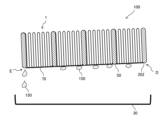
- a drain pan 30 is disposed below the heat exchanger 100 to receive dew 150 generated in the heat exchanger 100.
- dew 150 occurs in the heat exchanger 100.
- the heat exchanger 100 is installed approximately horizontally, dew dripping during heat exchange is not taken into consideration. If the heat exchanger 100 is installed at an angle to the horizontal direction, the dew 150 falls from the lower apex 60 located at the bottom of the wire fin 1, or the lower apex 50 at the bottom end of the heat transfer tube 2.
- the dew 150 generated by the heat exchange flows to the lower apex 50 of the second end 202, which is located lower, of the first end 201 and second end 202 of the heat transfer tube 2.
- the dew 150 flows to the lower apex 60 of the corrugated portion 105, which is located lower, in the wire fin 1.
- the dew 150 stays at the lower apex 50 and lower apex 60, and when it grows to a certain size, it turns into droplets and falls downward.
- the dew 150 temporarily stays at both ends in the longitudinal direction Z of the wire fin 1, i.e., at the lower arc-shaped second end 202 of the first end 201 or the second end 202, or at multiple locations on the lower apex 60 of the wavy portion 105, until it grows, and then falls downward.
- the dew 150 temporarily stays at multiple locations on the lower apex 60 of the wavy portion 105 until it grows, and then falls downward.
- the dew 150 also falls downward from the lower apex 50 of the heat transfer tube 2.
- the dew 150 flows to multiple locations of the lower apexes 50 and 60 in the periodic interval direction U, in which the lower apexes 50 of the second end 202 of the heat transfer tube 2 and the lower apexes 60 of the corrugated portion 105 of the wire fin 1 exist, and in the overlapping direction V.
- the dew 150 then falls into the drain pan 30 below the heat exchanger 100.
- the dew 150 also remains at multiple locations of the lower apexes 50 in the step direction X, in which the lower apexes 50 of the heat transfer tube 2 exist, and in the refrigerant flow path direction Y, and the dew 150 grows to a certain size.
- the dew 150 can then fall from a wide range of the lower apexes 50 and 60, i.e., from multiple locations, into the drain pan 30 provided below the heat exchanger 100.
- FIG. 10 is a partial perspective view of the heat exchanger 100 according to the third embodiment.
- FIG. 11 is a schematic diagram of the heat exchanger 100 according to the third embodiment, viewed in the refrigerant flow path direction Y.
- FIG. 12 is a schematic diagram of the heat exchanger 100 according to the third embodiment, viewed in the stage direction X.
- the lower apex 50 of the heat transfer tube 2 and the lower apex 60 of the wire fin arc portion 103 of the wire fin 1 are connected by a first connecting wire 70.
- the dew 150 temporarily accumulates at multiple locations below the heat exchanger 100, and then falls below the heat exchanger 100 from the multiple locations.
- the temporarily accumulated dew 150 travels along the first connecting wire 70, is collected at a predetermined location, and falls from the predetermined location into the drain pan 30.
- the first connecting wire 70 prevents the temporarily accumulated dew 150 from splashing out of the air outlet before it falls.
- the dew 150 is collected in a specified location and discharged into the drain pan 30 to prevent temporary retention of condensation water generated in the heat exchanger 100. This eliminates problems with drainage treatment caused by temporary retention of dew 150, or problems with dew splashing from the air outlet.
- the first connecting wire 70 connects the lower apex 50 of the heat transfer tube 2 to the lower apex 60 of the wire fin arc portion 103 of the wire fin 1.
- the first connecting wire 70 connects the lower apex 50 of the heat transfer tube 2 to the lower apex 60 of the wire fin arc portion 103 of the wire fin 1 in the step direction X of the heat transfer tube 2 and in the periodic spacing direction U of the wire fin 1. Therefore, it connects adjacent wire fin arc portions 103 in the wave amplitude direction W of the wire fin 1.
- the heat exchanger 100 is also installed in a predetermined direction, for example, in the row direction X, at a predetermined angle, for example, 3 to 10 degrees.
- a predetermined angle for example, 3 to 10 degrees.
- the right side D of FIG. 11, which is one side of the row direction X is installed lower than the left side E of FIG. 11, which is the other side of the row direction X, so that dew 150 flows from the right side D of FIG. 11, which is one side of the row direction X, to the left side E of FIG. 11, which is the other side of the row direction X. Therefore, the dew 150 generated in the heat exchanger 100 is collected below the heat exchanger 100 by gravity, but the heat exchanger 100 is inclined by a predetermined angle.
- the dew 150 collected below the heat exchanger 100 flows along the first connection wire 70 in a predetermined direction, for example, from the right side D of FIG. 11, which is one side of the row direction X, to the left side E of FIG. 11, which is the other side of the row direction X. Then, the dew 150 collects at the lower end of the left side E of FIG. 11, which is the other side of the row direction X of the heat transfer tube 2, and falls downward from there. Therefore, the dew 150 generated in the heat exchanger 100 can be collected at the lower end E on the left side of FIG. 11, which is the other side of the row direction X of the heat transfer tube 2, without accumulating.
- the dew 150 generated in the heat exchanger 100 is collected at one end, the left side E in FIG. 11, in the row direction X, which is a predetermined direction, making it easier to drain and preventing the dew 150 from accumulating, which also prevents the dew from splashing.
- the lower top 50 of the heat transfer tube 2, from which dew 150 tends to drip as droplets, and the lower top 60 of the wire fin 1 are connected by a plurality of first connecting wires 70, and the heat exchanger 100 is inclined in a predetermined direction, for example, in the row direction X.
- the dew 150 does not accumulate at the lower end of the heat exchanger 100, but flows along the first connecting wire 70 to the end of the heat transfer tube 2 in the row direction X, which is the end of the heat exchanger 100 in the inclined direction, and is drained by falling downward.
- FIG. 13 is a perspective view showing the second connection wire 75 of the heat exchanger 100 according to the third embodiment.
- the upper apexes 65 of the wavy portions 105 may be connected by the second connection wire 75.
- the second connection wire 75 connects the upper apexes 65 of the wavy portions 105 in a predetermined direction of the heat transfer tube 2, for example, in the row direction X. This further increases the heat transfer area, resulting in a heat exchanger 100 with even higher performance.
- Figures 10 to 13 illustrate an example in which the first connection wire 70 or the second connection wire 75 is arranged to extend in a predetermined direction, for example, in the row direction X, at the lower or upper part of the heat exchanger 100.
- the first connection wire 70 improves drainage, making it difficult for dew 150 to temporarily accumulate at the lower part of the heat exchanger 100.
- the first connection wire 70 and the second connection wire 75 increase the heat transfer area.
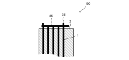
- FIG. 14 is a perspective view showing the third connection wire 85 of the heat exchanger 100 according to the third embodiment.
- FIG. 15 is a schematic diagram of the heat exchanger 100 of FIG. 14 viewed in the row direction X.
- the heat exchanger 100 may include a third connection wire 85.
- the third connection wire 85 is a depth direction connection wire that extends in the depth direction V in addition to the first connection wire 70 and the second connection wire 75 that extend in the row direction X of the heat transfer tube 2.
- the heat exchanger 100 may be installed at a predetermined angle, for example, 3 to 10 degrees, in a predetermined direction, for example, in the refrigerant flow direction Y.
- the heat exchanger 100 is installed lower on one side in the refrigerant flow direction Y than on the other side, so it is inclined so that the dew 150 flows from one side of the refrigerant flow direction Y to the other side. Therefore, the dew 150 generated on the heat exchanger 100 is collected below the heat exchanger 100 by gravity, but the heat exchanger 100 is inclined at a predetermined angle in the predetermined direction.
- the dew 150 collected below the heat exchanger 100 flows along the third connection wire 85 from one side to the other in the refrigerant flow direction Y, for example, and collects at the other lower end of the heat transfer tube 2 in the refrigerant flow direction Y, and falls downward from there. Therefore, the dew 150 generated on the heat exchanger 100 can be collected at the other lower end of the heat transfer tube 2.
- the dew 150 generated in the heat exchanger 100 can be collected at one end in a predetermined direction, for example, in the refrigerant flow path direction Y, so that the dew 150 is prevented from accumulating. This makes it easier to drain the dew 150, and since the accumulation of the dew 150 can be prevented, dew splashing or dripping can also be prevented.
- the heat exchanger 100 may include a second connection wire 75 in addition to the third connection wire 85.
- the second connection wire 75 is arranged at a substantially right angle to the third connection wire 85, which is a depth direction connection wire.
- the second connection wire 75 and the third connection wire 85 are formed in a mesh shape.
- the second connection wires 75 are arranged at the lower or upper part of the heat exchanger 100 so as to extend toward the row direction X of the heat transfer tubes 2, and are arranged in a line at approximately right angles to the third connection wires 85 in the refrigerant flow path direction Y.
- the second connection wires 75 are arranged so as to extend between the upper apexes 65 or between the lower apexes 60 of the wavy portions 105 of the wire fins 1 in the row direction X of the heat transfer tubes 2, toward the periodic spacing direction U of the wire fins 1.
- the third connection wires 85 are provided at the lower or upper part of the heat exchanger 100 so as to extend toward the refrigerant flow direction Y of the heat transfer tube 2, and multiple wires are arranged approximately parallel to each other in the row direction X.
- the second connecting wire 75 is a second row-wise connecting wire arranged to extend in the refrigerant flow path direction Y of the heat transfer tube 2 toward the stacking depth direction V of the wire fin 1.
- the second connecting wire 75 connects the upper apexes 65 or the lower apexes 60 of the wavy portion 105 of the wire fin 1.
- the third connection wire 85 and the second connection wire 75 are arranged in a mesh pattern, crossing at approximately right angles, and the third connection wire 85 and the second connection wire 75 are connected at their intersections. In this manner, the third connection wire 85 and the second connection wire 75 are arranged in a mesh pattern, crossing at approximately right angles. Therefore, the dew 150 is well drained in both the row direction X of the heat transfer tube 2 and the refrigerant flow path direction Y of the heat transfer tube 2, and a heat exchanger 100 in which dripping and splashing of dew is unlikely to occur can be obtained.
- the second connection wire 75 and the third connection wire 85 do not have to be arranged to intersect at approximately right angles, and the second connection wire 75 may be arranged to intersect the third connection wire 85 at a predetermined angle.
- the direction in which the second connection wire 75 or the third connection wire 85 is arranged is perpendicular to the inclination direction of the heat exchanger 100, depending on the inclination direction of the heat exchanger 100.
- the direction in which the other of the second connection wire 75 or the third connection wire 85 is arranged is perpendicular to the inclination direction of the heat exchanger 100.
- the second connection wire 75 is arranged to intersect with the third connection wire 85 at a predetermined angle. Even if the heat exchanger 100 is tilted in the direction in which either the second connection wire 75 or the third connection wire 85 is arranged, the direction in which the other of the second connection wire 75 or the third connection wire 85 is arranged does not face a direction perpendicular to the tilt direction of the heat exchanger 100. This improves the drainage of dew 150.
- either the second connection wire 75 or the third connection wire 85, or both are connected to the lower apex 50 of the heat transfer tube 2, the second end 202 of the wire fin 1, or the lower apex 60 of the wire fin 1.
- either the second connection wire 75 or the third connection wire 85, or both connect the lower apex 50 of the heat transfer tube 2, the second end 202 of the wire fin 1, or the lower apex 60 of the wire fin 1.
- This allows dew 150 generated in the heat exchanger 100 to be collected at a predetermined location, for example, near the end of the heat transfer tube 2 in the row direction X, or near the end of the heat transfer tube 2 in the refrigerant flow direction Y.
- both the second connection wire 75 and the third connection wire 85 may be connected in a mesh pattern to the lower apex 50 of the heat transfer tube 2, the second end 202 of the wire fin 1, or the lower apex 60 of the wire fin 1 to form the heat exchanger 100.
- the dew 150 generated in the heat exchanger 100 is collected at a predetermined location, for example, near the end of the heat transfer tube 2 in the row direction X, or near the end of the heat transfer tube 2 in the refrigerant flow direction Y.
- the dew 150 can be collected at a predetermined location without limiting the inclination direction of the heat exchanger 100, improving the freedom of installation of the heat exchanger 100.
- the dew 150 is prevented from falling from the wide area at the lower end, and the dew 150 can be concentrated in a specific area where dew dripping or dew splashing is unlikely to occur, for example, near the end of the heat transfer tube 2 in the row direction X, or near the end of the heat transfer tube 2 in the refrigerant flow path direction Y. This makes it possible to obtain a heat exchanger 100 and an air conditioner 140 in which dew dripping or dew splashing is unlikely to occur.
- the first connecting wire 70 connects the ends of the second wire fins 12 in the amplitude direction W.
- the dew 150 that has collected below the heat exchanger 100 flows along the first connecting wire 70 and falls downward, so that the dew 150 generated in the heat exchanger 100 does not stagnate but is collected at the lower end of the heat transfer tube 2. This prevents the dew from splashing, and the dew 150 is collected, making it easier to drain.
- Embodiment 4 is a schematic diagram of a heat exchanger 100 according to embodiment 4.
- Fig. 17 is a side view of a blower fan 500 arranged together with the heat exchanger 100 according to embodiment 4.
- Embodiment 4 differs from embodiments 1 to 3 in that the heat exchanger 100 is circular in shape, in that the heat exchanger 100 is linear.
- parts common to embodiments 1 to 3 are denoted by the same reference numerals and description thereof is omitted, and the following description focuses on the differences from embodiments 1 to 3.
- the heat exchanger 100 is configured with a heat transfer tube 2, a third wire fin 16, and a fourth wire fin 17 arranged in a circular shape.
- the heat exchanger 100 is arranged in a circular shape around a blower fan 500, which is a circular fan.
- the heat exchanger 100 is arranged radially and outwardly away from the fan outer diameter 501 of the blower fan 500, for example, a propeller fan, a sirocco fan, or a crossflow fan, by a predetermined gap 510.
- the heat exchanger 100 is configured such that the refrigerant flow path direction Y of the heat transfer tube 2 and the third wire fin 16 and the fourth wire fin 17 are arranged substantially parallel to the axial direction of the blower fan 500.
- the periodic interval direction U of the waves of the third wire fin 16 and the fourth wire fin 17 arranged in a circular shape is the circumferential direction of the third wire fin 16 and the fourth wire fin 17 in the heat exchanger 100 arranged in a circular shape.
- the periodic interval direction U of the waves of the third wire fin 16 and the fourth wire fin 17 is the circumferential direction of the fan outer diameter 501 of the blower fan 500.
- the third wire fin 16 and the fourth wire fin 17 are formed into a wavy shape using wire such as aluminum in the heat exchanger 100, the wavy portion 115 and the wavy portion 125 can be freely deformed. This increases the degree of freedom in arranging the heat transfer tubes 2, and makes it possible to freely arrange the shape of the heat exchanger 100. Therefore, the shape of the heat exchanger 100 can be freely selected, such as a circular, sector-shaped, or U-shaped shape.
- the heat exchanger 100 which is composed of the heat transfer tube 2, the third wire fin 16, and the fourth wire fin 17, is arranged radially with respect to the fan outer diameter 501 of the blower fan 500.
- the heat transfer tube 2, the third wire fin 16, and the fourth wire fin 17 are arranged in an arc shape so that the predetermined radial gap 510 between the blower fan 500 and the heat exchanger 100 is approximately equal at any position and angle in the circumferential direction of the blower fan 500.
- the heat exchanger 100 is arranged around the blower fan 500, centering on the rotation axis 530, so as to surround the blower fan 500 around the rotation axis 530 of the blower fan 500.
- the step direction X of the heat transfer tube 2 and the periodic interval direction U of the third wire fin 16 and the fourth wire fin 17 correspond to the circumferential direction of the blower fan 500.
- FIG. 16 shows an example in which the heat exchanger 100 is arranged to surround the entire circumference of the circular blower fan 500 in the circumferential direction, but the heat exchanger 100 does not have to be configured to surround the entire circumference of the circular blower fan 500 in the circumferential direction.
- the heat exchanger 100 may be arranged in an arc shape or a fan shape in the circumferential direction of the circular blower fan 500 as long as a predetermined air volume and a predetermined heat exchange efficiency are obtained.
- the long axis direction Z of the heat transfer tube 2 is arranged to face the blower fan 500, so that wind or air can be efficiently applied to the third wire fin 16 and the fourth wire fin 17. This improves the heat exchange efficiency.
- the heat exchanger 100 can be configured in a circular or U-shape to surround the blower fan 500 without bending the heat transfer tube 2.
- the heat transfer tube 2 is arranged so that the long axis direction Z faces the blower fan 500, so that air can be efficiently directed at the third wire fin 16 and the fourth wire fin 17. This improves the heat exchange efficiency.
- the heat exchanger 100 which is composed of the heat transfer tube 2, the third wire fin 16, and the fourth wire fin 17, is arranged in a circular, arc, or sector shape with respect to the circular blower fan 500.
- the heat exchanger 100 is arranged radially in the circumferential direction and close to the circular blower fan 500 with a predetermined gap 510 that is approximately equally spaced. Therefore, the air volume of the blower fan 500 can be efficiently obtained over the entire circumferential area of the heat exchanger 100, i.e., the entire arc-shaped area, so that the heat exchanger 100 can be obtained with improved heat exchange efficiency and leading to a miniaturization of the product.
- the heat exchanger 100 can be miniaturized, by using the heat exchanger 100, it is possible to obtain a small, lightweight, low-cost, and highly efficient outdoor unit of the air conditioner 140, the air conditioner 140, the heat source unit of the water heater, or the water heater.
- the heat exchanger 100 is formed by arranging the third wire fins 16, in which the wires are formed in a wavy shape, and the fourth wire fins 17 such that their periodic spacing direction U is aligned with the row direction X of the heat transfer tubes 2, and thermally joining the heat transfer tubes 2.
- the heat exchanger 100 is arranged in a housing so as to be circular, arc-shaped, or U-shaped so as to surround the periphery of the blower fan 500, which is a circular fan. Therefore, the heat exchanger 100 can provide a small, lightweight, low-cost, and highly efficient indoor unit or outdoor unit of an air conditioner 140, an air conditioner 140, a heat source unit for a water heater, or a water heater.
- the heat exchanger 100 is circular, arc-shaped, or U-shaped. Even if the heat exchanger 100 is circular, sector-shaped, U-shaped, or other shaped, the wavy portion 105 can be freely deformed due to the wavy wire fins 1, so the degree of freedom in arranging the heat transfer tubes 2 is increased, and the shape of the heat exchanger 100 can be freely selected.
- the heat transfer tubes 2 can be arranged in a circular, arcuate, or U-shape. Whether the heat transfer tubes 2 are arranged in a circular, arcuate, or U-shape, the wavy portion 105 can be freely deformed by the wire fins 1 shaped in a shape, so the degree of freedom in arranging the heat transfer tubes 2 is increased, and the shape of the heat exchanger 100 can be freely selected.
- FIG. 18 is a schematic diagram of an air conditioner 140 including a heat exchanger 100 according to embodiment 5.
- the fifth embodiment differs from the first to third embodiments in that the heat exchanger 100 is arranged to surround the blower fan 500, and is arranged in a straight line.
- the fifth embodiment differs from the fourth embodiment in that the overlap depth direction V of the fifth wire fin 18 and the sixth wire fin 19 is arranged in a direction substantially perpendicular to the rotation axis 530 of the blower fan 500, which is the refrigerant flow path direction Y of the heat transfer tube 2.
- the fifth embodiment differs from the fourth embodiment in that the overlap depth direction V of the third wire fin 16 and the fourth wire fin 17 is arranged in a direction substantially parallel to the rotation axis 530 of the blower fan 500, which is the refrigerant flow path direction Y of the heat transfer tube 2.
- the same reference numerals are used to designate the parts common to the first to fourth embodiments, and the description will be omitted, and the differences from the first to fourth embodiments will be mainly described.
- the heat exchanger 100 uses the fifth wire fin 18 and the sixth wire fin 19, which are formed into a wavy shape using wire such as aluminum, and can be freely deformed in the wavy portion. This increases the degree of freedom in arranging the heat transfer tubes 2, making it possible to freely arrange the shape of the heat exchanger 100. Therefore, the shape of the heat exchanger 100 can be freely selected, such as a circular, sector-shaped, or U-shaped shape.
- the heat exchanger 100 is arranged in a U-shape around the blower fan 500 so as to surround at least a portion of the blower fan 500.
- the heat exchanger 100 is housed in a housing 130 together with the blower fan 500 to form an air conditioner 140.
- the housing 130 is, for example, an indoor unit placed inside a room.
- the refrigerant flow path direction Y of the heat transfer tube 2, and the overlapping direction V of the fifth wire fin 18 and the sixth wire fin 19 are arranged at approximately right angles to the axial direction of the blower fan 500.
- the heat exchanger 100 is composed of the heat transfer tube 2, the fifth wire fin 18, and the sixth wire fin 19.
- the heat exchanger 100 is composed of straight parts and arc-shaped parts in the row direction X.
- the straight parts are composed of a first straight part M1, a second straight part M2, and a third straight part M3, and the arc-shaped part, for example a 1/4 arc, is composed of a first arc part N1 and a second arc part N2.
- the first straight section M1 is provided in the axial direction of the rotating shaft 530 so as to face the blower fan 500.
- the refrigerant flow path direction Y of the heat transfer tube 2 constituting the first straight section M1 is arranged to be approximately parallel to the blowing direction of the blower fan 500.
- the second straight section M2 and the third straight section M3 are provided on the side of the blower fan 500 and are arranged in a direction perpendicular to the rotating shaft 530.
- a first arc portion N1 is provided between the first straight portion M1 and the second straight portion M2, connecting the first straight portion M1 and the second straight portion M2 and having an arc shape.
- a second arc portion N2 is provided between the first straight portion M1 and the third straight portion M3, connecting the first straight portion M1 and the third straight portion M3 and having an arc shape.
- the number of wavy portions of the fifth wire fin 18 and the sixth wire fin 19 provided between adjacent heat transfer tubes 2 is less than the number of wavy portions of the fifth wire fin 18 and the sixth wire fin 19 provided between adjacent heat transfer tubes 2 in the first straight portion M1 or the second straight portion M2. Therefore, in the first arc portion N1, the distance between adjacent heat transfer tubes 2 is reduced, and the radius of the arc forming the first arc portion N1 can be reduced, thereby making it possible to obtain a small and compact heat exchanger 100.
- the number of wavy portions of the fifth wire fin 18 and the sixth wire fin 19 provided between adjacent heat transfer tubes 2 in the first arc portion N1 may be equal to the number of wavy portions of the fifth wire fin 18 and the sixth wire fin 19 provided between adjacent heat transfer tubes 2 in the first straight portion M1 or the second straight portion M2.
- the spacing between adjacent heat transfer tubes 2 in the first arc portion N1 decreases, and the radius of the arc forming the first arc portion N1 decreases. Therefore, a small and compact heat exchanger 100 can be obtained.
- the number of wavy portions of the fifth wire fin 18 and the sixth wire fin 19 provided between adjacent heat transfer tubes 2 is less than the number of wavy portions of the fifth wire fin 18 and the sixth wire fin 19 provided between adjacent heat transfer tubes 2 in the first straight portion M1 or the third straight portion M3. Therefore, in the second arc portion N2, the distance between adjacent heat transfer tubes 2 is reduced, and the radius of the arc forming the second arc portion N2 can be reduced, thereby making it possible to obtain a small and compact heat exchanger 100.
- the heat exchanger 100 can be configured in a circular or U-shape to surround the blower fan 500 without bending the heat transfer tube 2.
- the long axis direction Z of the heat transfer tube 2 is arranged to face the blower fan 500, so that air can be efficiently directed at the fifth wire fin 18 and the sixth wire fin 19. This improves the heat exchange efficiency.
- the periodic spacing direction U of the waves of the fifth wire fin 18 and the sixth wire fin 19 arranged in a circular or U-shape is the periodic spacing direction U of the waves of the fifth wire fin 18 and the sixth wire fin 19 of the heat exchanger 100 arranged in a circular or U-shape, and is therefore the circumferential direction of the circular heat exchanger 100 or the U-shape direction of the U-shaped heat exchanger 100.
- the heat exchanger 100 can be constructed without bending the heat transfer tube 2. Therefore, the heat exchanger 100 can be constructed and stored in accordance with the storage space or storage shape of the product without causing a decrease in pressure resistance or reliability due to deformation of the heat transfer tube 2.
- the periodic spacing direction U of the fifth wire fin 18 and the sixth wire fin 19, in which the wire is shaped in a wavy shape, is arranged along the row direction X of the heat transfer tube 2, and the fifth wire fin 18 and the sixth wire fin 19 are thermally joined to the heat transfer tube 2. Since the heat exchanger 100 can be formed in a circular, arcuate, or U-shape, it can be arranged in the housing so as to surround the periphery of the circular blower fan 500. This makes it possible to obtain a small, lightweight, low-cost, and highly efficient indoor unit of the air conditioner 140, outdoor unit, air conditioner 140, heat source unit of a water heater, or water heater.
- the heat exchanger 100 since the heat exchanger 100 provided in the housing 130 has wire fins 1, the heat exchanger 100 can be arranged to surround the blower fan without bending the heat transfer tube 2. Therefore, the heat exchanger 100 can be configured to fit the storage space or storage shape of the product and stored in the air conditioner 140 without causing a decrease in pressure resistance or reliability due to deformation of the heat transfer tube 2, etc.
- the housing 130 is, for example, an indoor unit placed indoors, making it possible to obtain a small, lightweight, low-cost, and highly efficient indoor unit.
- Embodiment 6 Fig. 19 is a perspective view of a heat exchanger 100 according to embodiment 6.
- Fig. 20 is a schematic diagram of the heat exchanger 100 according to embodiment 6 as viewed in the refrigerant flow path direction Y.
- Embodiment 6 differs from embodiments 1 to 5 in that the heat transfer tubes 2 are circular tubes.
- parts common to embodiments 1 to 5 are denoted by the same reference numerals and description thereof is omitted, and the following description focuses on the differences from embodiments 1 to 5.
- the heat exchanger 100 is composed of a heat transfer tube 800, which is a circular tube, and a seventh wire fin 850 formed for the circular tube.
- a plurality of heat transfer tubes 800 are arranged in a predetermined direction at predetermined intervals, preferably at equal intervals.
- the seventh wire fin 850 is thermally connected to the plurality of heat transfer tubes 800.
- the specified direction in which the seventh wire fin 850 is connected is referred to as the row direction L.
- the direction in which the refrigerant flows in the refrigerant flow path 900 of the heat transfer tube 800 is the longitudinal direction or the depth direction, and is referred to as the refrigerant flow path direction M.
- the heat transfer tube 800 is configured such that multiple refrigerant flow paths 900 having a specified length are arranged side by side so as to overlap each other.
- the multiple heat transfer tubes 800 are arranged side by side in a direction approximately perpendicular to the wave direction of the seventh wire fin 850.
- the direction in which the multiple heat transfer tubes 800 are arranged side by side is referred to as the row direction N of the circular tube.
- the seventh wire fin 850 is formed into a wave shape using a wire such as an aluminum wire.
- the direction in which the waves advance is called the periodic interval direction U
- the direction of the amplitude of the waves is called the amplitude direction W.
- the seventh wire fin 850 is composed of a fixed portion 870 and a wavy portion 860.
- the fixed portion 870 has a wire fin arc portion 871, and is fixed to the heat transfer tube 2 by line contact at the wire fin arc portion 871.
- the wavy portion 860 is formed so that the wave shape advances in the periodic interval direction U using the wire.
- the seventh wire fin 850 is arranged at a predetermined interval, for example, at equal intervals or unequal intervals, in the refrigerant flow path direction M of the heat transfer tube 800.
- a plurality of seventh wire fins 850 for example, a predetermined number, are provided.
- the refrigerant flow path direction M of the heat transfer tubes 800 which are provided at a predetermined interval, is referred to as the overlap direction V or overlap depth direction V.
- the wavy seventh wire fin 850 can be used even if the heat transfer tube 800 is a small-diameter circular tube.
- the seventh wire fin 850 has a fixed portion 870 and a wavy portion 860 formed in a wavy shape. Even if there is some variation in the dimensions of the spacing between adjacent heat transfer tubes 800, when the heat transfer tubes 800 are inserted into the fixed portion 870 in a press-fit manner, the wavy portion 860 expands and contracts due to the spring characteristics of the wavy portion 860, absorbing the variation in spacing. This allows the heat transfer tube 800 and the seventh wire fin 850 to be thermally in close contact. This improves assembly ease and heat transfer performance.
- the seventh wire fin 850 in which the wire is shaped into a wave-like shape, has its wave periodic spacing direction U arranged in the step direction of the heat transfer tube 800, and is thermally joined to the heat transfer tube 800 to form the heat exchanger 303.
- the heat exchanger 100 makes it possible to obtain a small, lightweight, low-cost, and highly efficient air conditioner 140.
- the heat exchanger 100 makes it possible to obtain a small, lightweight, low-cost, and highly efficient indoor unit, outdoor unit, air conditioner 140, heat source unit for a water heater, or water heater.
- the heat exchanger 100 can also be arranged in a circular, arc-like, or U-shaped configuration so as to surround the periphery of the blower fan 500, which is a circular fan. This allows the use of the heat exchanger 100 to provide a small, lightweight, low-cost, and highly efficient air conditioner 140. Furthermore, by arranging the row direction N of the heat transfer tubes 800 to face the blower fan 500, wind or air can be efficiently directed at the seventh wire fin 850. This improves heat exchange efficiency.
- one wire fin 1, the first wire fin 11, or the second wire fin 12 is folded back at the folding back portion 1a, the folding back portion 11a, or the folding back portion 12a, respectively.
- One wire fin 1, the first wire fin 11, or the second wire fin 12 is folded back at the folding back portion 1a, the folding back portion 11a, or the folding back portion 12a, respectively, and thus arranged in a plurality in the refrigerant flow path direction Y.
- the third wire fin 16, the fourth wire fin 17, the fifth wire fin 18, the sixth wire fin 19, or the seventh wire fin 850 may also be folded back at the heat transfer tube 2a or the heat transfer tube 800a provided at the outermost end in the row direction X.
- the third wire fin 16, the fourth wire fin 17, the fifth wire fin 18, the sixth wire fin 19, or the seventh wire fin 850 can also be folded back to be arranged in multiple numbers in the refrigerant flow path direction Y. There is no need to cut off one of the third wire fin 16, the fourth wire fin 17, the fifth wire fin 18, the sixth wire fin 19, or the seventh wire fin 850, either, so a low-cost heat exchanger 100 can be obtained.
- FIG. 21 is a schematic diagram of a heat exchanger 100 according to a modified example of embodiment 6. As shown in FIG. 21, in the heat exchanger 100, the coiled, continuous wire may be used as a single eighth wire fin 851 in its original state. This can improve workability and work efficiency.
- the wire fins 1 do not have to be folded back at the folding back portion 1a and arranged in multiple positions in the refrigerant flow direction Y, but may be arranged in multiple positions in the refrigerant flow direction Y of the heat transfer tube 2.
- the heat exchanger 100 is composed of the wire fins 1 and the heat transfer tubes 2.
- the heat exchanger 100 is arranged inside the housing 130 to constitute the air conditioner 140.
- the wire fins 1 are formed in a wavy shape using wire.
- the heat transfer tubes 2 are, for example, flat tubes and arranged in the row direction X.
- the wire fins 1 are joined to the heat transfer tubes 2 so that the periodic interval direction U, which is the direction in which the waves of the wire fins 1 advance, is along the row direction X.
- a first connecting wire 70 is connected to the lower apex 50 of the heat transfer tubes 2, the second end 202 of the wire fins 1, or the lower apex 60 of the wire fins 1.
- a drain pan 30 is arranged below the heat exchanger 100 inside the housing 130 to receive the dew 150 that falls from the heat exchanger 100.
- the heat exchanger 100 is arranged inside the housing 130 so that it is tilted at a predetermined angle.
- a first connection wire 70 is provided at the bottom of the heat exchanger 100, and the heat exchanger 100 is installed at an angle, so that the location where the dew 150 generated in the heat exchanger 100 falls is specified to a specific location.
- the heat exchanger 100 may be provided with a second connection wire 75 or a third connection wire 85. This increases the freedom of where the drain pan 30 is installed, and reduces the size of the drain pan 30.
- the first connection wire 70 or the second connection wire 75 may be connected in a mesh pattern, crossing at a direction approximately perpendicular to the third connection wire 85. This allows for good drainage of the dew 150 in both the row direction X of the heat transfer tube 2 and the refrigerant flow direction Y of the heat transfer tube 2, resulting in a heat exchanger 100 or air conditioner 140 in which dew dripping or dew splashing is unlikely to occur.
- the heat exchanger 100 may be used in a water heater, not in an air conditioner 140.
- the heat exchanger 100 may be used in an indoor unit, an outdoor unit, a heat source unit of a water heater, or a water heater.
- the wire fin 1 may be the first wire fin 11 to the eighth wire fin 851.
- the first connecting wire 70 may be the second connecting wire 75 or the third connecting wire 85.
- the heat transfer tube 2 may be the heat transfer tube 800, which is a circular tube.
- the first connecting wire 70 may be connected to the lower apex 50 of the heat transfer tube 2, the second end 202 of the wire fin 1, or the lower apex 60 of the wire fin 1.
- the air conditioner 140 also includes a heat exchanger 100 that is thermally joined to the heat transfer tube 2, and in which the wire fins 1 are arranged so that the periodic spacing direction U of the wire fins 1 formed into a wavy shape by wire line is aligned with the step direction of the heat transfer tube 2.
- the periodic spacing direction U of the wire fins 1 is the direction in which the waves advance, which is the direction of the periodic spacing.
- the air conditioner 140 includes a blower fan 500 for blowing the air that has undergone heat exchange via the heat exchanger 100 indoors or outdoors.
- the air conditioner 140 also includes an indoor unit or an outdoor unit in which the heat exchanger 100 is arranged in a circular, arc-like, or U-shaped manner so as to surround the periphery of the blower fan 500. This makes it possible to obtain a small, lightweight, low-cost, and highly efficient air conditioner 140.
Landscapes
- Physics & Mathematics (AREA)
- Engineering & Computer Science (AREA)
- Geometry (AREA)
- Thermal Sciences (AREA)
- Mechanical Engineering (AREA)
- General Engineering & Computer Science (AREA)
- Heat-Exchange Devices With Radiators And Conduit Assemblies (AREA)
Priority Applications (2)
| Application Number | Priority Date | Filing Date | Title |
|---|---|---|---|
| PCT/JP2023/001258 WO2024154240A1 (ja) | 2023-01-18 | 2023-01-18 | 熱交換器及び空気調和機 |
| JP2024571487A JP7829742B2 (ja) | 2023-01-18 | 2023-01-18 | 熱交換器及び空気調和機 |
Applications Claiming Priority (1)
| Application Number | Priority Date | Filing Date | Title |
|---|---|---|---|
| PCT/JP2023/001258 WO2024154240A1 (ja) | 2023-01-18 | 2023-01-18 | 熱交換器及び空気調和機 |
Publications (1)
| Publication Number | Publication Date |
|---|---|
| WO2024154240A1 true WO2024154240A1 (ja) | 2024-07-25 |
Family
ID=91955643
Family Applications (1)
| Application Number | Title | Priority Date | Filing Date |
|---|---|---|---|
| PCT/JP2023/001258 Ceased WO2024154240A1 (ja) | 2023-01-18 | 2023-01-18 | 熱交換器及び空気調和機 |
Country Status (2)
| Country | Link |
|---|---|
| JP (1) | JP7829742B2 (https=) |
| WO (1) | WO2024154240A1 (https=) |
Citations (6)
| Publication number | Priority date | Publication date | Assignee | Title |
|---|---|---|---|---|
| JPH0448193A (ja) * | 1990-06-18 | 1992-02-18 | Toshiba Corp | 細線フィン型熱交換器 |
| JPH04217791A (ja) * | 1990-12-18 | 1992-08-07 | Showa Alum Corp | 細線構造のフィンを有する熱交換器 |
| JPH08320192A (ja) * | 1994-07-22 | 1996-12-03 | Mitsubishi Electric Corp | 熱交換器及びその製造方法、冷凍システム、空調装置、熱交換器の製造装置及びその治具 |
| JP2010027998A (ja) * | 2008-07-24 | 2010-02-04 | Usui Kokusai Sangyo Kaisha Ltd | 扁平コイル状フィン部材を有する伝熱面構造及びその製造方法 |
| WO2018159601A1 (ja) * | 2017-02-28 | 2018-09-07 | 三菱マテリアル株式会社 | 熱交換部材 |
| WO2020065697A1 (ja) * | 2018-09-25 | 2020-04-02 | 三菱電機株式会社 | 熱交換器、該熱交換器を備えた空気調和機、及び該熱交換器を備えた冷蔵庫 |
Family Cites Families (2)
| Publication number | Priority date | Publication date | Assignee | Title |
|---|---|---|---|---|
| JPS6179775U (https=) * | 1984-10-26 | 1986-05-28 | ||
| WO2001067020A1 (en) | 2000-03-06 | 2001-09-13 | Hitachi, Ltd. | Heat exchanger, air conditioner, outdoor device, and indoor device |
-
2023
- 2023-01-18 JP JP2024571487A patent/JP7829742B2/ja active Active
- 2023-01-18 WO PCT/JP2023/001258 patent/WO2024154240A1/ja not_active Ceased
Patent Citations (6)
| Publication number | Priority date | Publication date | Assignee | Title |
|---|---|---|---|---|
| JPH0448193A (ja) * | 1990-06-18 | 1992-02-18 | Toshiba Corp | 細線フィン型熱交換器 |
| JPH04217791A (ja) * | 1990-12-18 | 1992-08-07 | Showa Alum Corp | 細線構造のフィンを有する熱交換器 |
| JPH08320192A (ja) * | 1994-07-22 | 1996-12-03 | Mitsubishi Electric Corp | 熱交換器及びその製造方法、冷凍システム、空調装置、熱交換器の製造装置及びその治具 |
| JP2010027998A (ja) * | 2008-07-24 | 2010-02-04 | Usui Kokusai Sangyo Kaisha Ltd | 扁平コイル状フィン部材を有する伝熱面構造及びその製造方法 |
| WO2018159601A1 (ja) * | 2017-02-28 | 2018-09-07 | 三菱マテリアル株式会社 | 熱交換部材 |
| WO2020065697A1 (ja) * | 2018-09-25 | 2020-04-02 | 三菱電機株式会社 | 熱交換器、該熱交換器を備えた空気調和機、及び該熱交換器を備えた冷蔵庫 |
Also Published As
| Publication number | Publication date |
|---|---|
| JP7829742B2 (ja) | 2026-03-13 |
| JPWO2024154240A1 (https=) | 2024-07-25 |
Similar Documents
| Publication | Publication Date | Title |
|---|---|---|
| JP4989979B2 (ja) | 熱交換器 | |
| JP4394002B2 (ja) | 傾斜したランスを有する熱交換器フィン | |
| EP2295919B1 (en) | Fin and heat exchanger having the same | |
| US5573059A (en) | Air conditioning machine | |
| US20070199686A1 (en) | Heat exchanger | |
| JP3947744B2 (ja) | コイル型フィンチューブ凝縮機 | |
| JP2010019534A (ja) | 熱交換器 | |
| JP3036892B2 (ja) | 熱交換器 | |
| US6009936A (en) | Heat exchanger | |
| JP5020886B2 (ja) | 熱交換器 | |
| JPH0829016A (ja) | ヒートポンプ用室外熱交換器 | |
| WO2024154240A1 (ja) | 熱交換器及び空気調和機 | |
| JP2001027484A (ja) | サーペンタイン型熱交換器 | |
| EP1455154A2 (en) | Evaporator | |
| JP2528121B2 (ja) | 熱交換器 | |
| JP5447842B2 (ja) | コルゲートフィン式熱交換器の排水構造 | |
| JP2020063883A (ja) | 熱交換器及び空気調和機 | |
| US20250109915A1 (en) | Louvered fin | |
| JP5958917B2 (ja) | フィンチューブ型熱交換器 | |
| JP2020034184A (ja) | 熱交換器および空気調和機 | |
| JP6377628B2 (ja) | フィン付きのチューブ要素、その製造方法およびフィン付きのチューブ要素を備えた熱交換器 | |
| JP7788862B2 (ja) | 熱交換器の製造方法および空気調和機の製造方法 | |
| JPH1123184A (ja) | 熱交換装置 | |
| JP2004150710A (ja) | 冷媒蒸発器およびその製造方法 | |
| JP2006162141A (ja) | 熱交換器 |
Legal Events
| Date | Code | Title | Description |
|---|---|---|---|
| 121 | Ep: the epo has been informed by wipo that ep was designated in this application |
Ref document number: 23917454 Country of ref document: EP Kind code of ref document: A1 |
|
| WWE | Wipo information: entry into national phase |
Ref document number: 2024571487 Country of ref document: JP |
|
| NENP | Non-entry into the national phase |
Ref country code: DE |
|
| 122 | Ep: pct application non-entry in european phase |
Ref document number: 23917454 Country of ref document: EP Kind code of ref document: A1 |