WO2024154231A1 - 環境認識装置、走行可能エリア決定方法及び電子制御装置 - Google Patents
環境認識装置、走行可能エリア決定方法及び電子制御装置 Download PDFInfo
- Publication number
- WO2024154231A1 WO2024154231A1 PCT/JP2023/001204 JP2023001204W WO2024154231A1 WO 2024154231 A1 WO2024154231 A1 WO 2024154231A1 JP 2023001204 W JP2023001204 W JP 2023001204W WO 2024154231 A1 WO2024154231 A1 WO 2024154231A1
- Authority
- WO
- WIPO (PCT)
- Prior art keywords
- area
- vehicle
- obstacle
- road surface
- road
- Prior art date
- Legal status (The legal status is an assumption and is not a legal conclusion. Google has not performed a legal analysis and makes no representation as to the accuracy of the status listed.)
- Ceased
Links
Images




Classifications
-
- B—PERFORMING OPERATIONS; TRANSPORTING
- B60—VEHICLES IN GENERAL
- B60W—CONJOINT CONTROL OF VEHICLE SUB-UNITS OF DIFFERENT TYPE OR DIFFERENT FUNCTION; CONTROL SYSTEMS SPECIALLY ADAPTED FOR HYBRID VEHICLES; ROAD VEHICLE DRIVE CONTROL SYSTEMS FOR PURPOSES NOT RELATED TO THE CONTROL OF A PARTICULAR SUB-UNIT
- B60W40/00—Estimation or calculation of non-directly measurable driving parameters for road vehicle drive control systems not related to the control of a particular sub unit, e.g. by using mathematical models
- B60W40/02—Estimation or calculation of non-directly measurable driving parameters for road vehicle drive control systems not related to the control of a particular sub unit, e.g. by using mathematical models related to ambient conditions
- B60W40/06—Road conditions
-
- B—PERFORMING OPERATIONS; TRANSPORTING
- B60—VEHICLES IN GENERAL
- B60W—CONJOINT CONTROL OF VEHICLE SUB-UNITS OF DIFFERENT TYPE OR DIFFERENT FUNCTION; CONTROL SYSTEMS SPECIALLY ADAPTED FOR HYBRID VEHICLES; ROAD VEHICLE DRIVE CONTROL SYSTEMS FOR PURPOSES NOT RELATED TO THE CONTROL OF A PARTICULAR SUB-UNIT
- B60W30/00—Purposes of road vehicle drive control systems not related to the control of a particular sub-unit, e.g. of systems using conjoint control of vehicle sub-units
- B60W30/08—Active safety systems predicting or avoiding probable or impending collision or attempting to minimise its consequences
- B60W30/095—Predicting travel path or likelihood of collision
- B60W30/0956—Predicting travel path or likelihood of collision the prediction being responsive to traffic or environmental parameters
-
- B—PERFORMING OPERATIONS; TRANSPORTING
- B60—VEHICLES IN GENERAL
- B60W—CONJOINT CONTROL OF VEHICLE SUB-UNITS OF DIFFERENT TYPE OR DIFFERENT FUNCTION; CONTROL SYSTEMS SPECIALLY ADAPTED FOR HYBRID VEHICLES; ROAD VEHICLE DRIVE CONTROL SYSTEMS FOR PURPOSES NOT RELATED TO THE CONTROL OF A PARTICULAR SUB-UNIT
- B60W30/00—Purposes of road vehicle drive control systems not related to the control of a particular sub-unit, e.g. of systems using conjoint control of vehicle sub-units
- B60W30/08—Active safety systems predicting or avoiding probable or impending collision or attempting to minimise its consequences
- B60W30/09—Taking automatic action to avoid collision, e.g. braking and steering
-
- B—PERFORMING OPERATIONS; TRANSPORTING
- B60—VEHICLES IN GENERAL
- B60W—CONJOINT CONTROL OF VEHICLE SUB-UNITS OF DIFFERENT TYPE OR DIFFERENT FUNCTION; CONTROL SYSTEMS SPECIALLY ADAPTED FOR HYBRID VEHICLES; ROAD VEHICLE DRIVE CONTROL SYSTEMS FOR PURPOSES NOT RELATED TO THE CONTROL OF A PARTICULAR SUB-UNIT
- B60W40/00—Estimation or calculation of non-directly measurable driving parameters for road vehicle drive control systems not related to the control of a particular sub unit, e.g. by using mathematical models
- B60W40/02—Estimation or calculation of non-directly measurable driving parameters for road vehicle drive control systems not related to the control of a particular sub unit, e.g. by using mathematical models related to ambient conditions
-
- B—PERFORMING OPERATIONS; TRANSPORTING
- B60—VEHICLES IN GENERAL
- B60W—CONJOINT CONTROL OF VEHICLE SUB-UNITS OF DIFFERENT TYPE OR DIFFERENT FUNCTION; CONTROL SYSTEMS SPECIALLY ADAPTED FOR HYBRID VEHICLES; ROAD VEHICLE DRIVE CONTROL SYSTEMS FOR PURPOSES NOT RELATED TO THE CONTROL OF A PARTICULAR SUB-UNIT
- B60W60/00—Drive control systems specially adapted for autonomous road vehicles
- B60W60/001—Planning or execution of driving tasks
- B60W60/0015—Planning or execution of driving tasks specially adapted for safety
-
- G—PHYSICS
- G08—SIGNALLING
- G08G—TRAFFIC CONTROL SYSTEMS
- G08G1/00—Traffic control systems for road vehicles
- G08G1/16—Anti-collision systems
-
- B—PERFORMING OPERATIONS; TRANSPORTING
- B60—VEHICLES IN GENERAL
- B60W—CONJOINT CONTROL OF VEHICLE SUB-UNITS OF DIFFERENT TYPE OR DIFFERENT FUNCTION; CONTROL SYSTEMS SPECIALLY ADAPTED FOR HYBRID VEHICLES; ROAD VEHICLE DRIVE CONTROL SYSTEMS FOR PURPOSES NOT RELATED TO THE CONTROL OF A PARTICULAR SUB-UNIT
- B60W2552/00—Input parameters relating to infrastructure
- B60W2552/35—Road bumpiness, e.g. potholes
Definitions
- the present invention relates to an environment recognition device, a method for determining a drivable area, and an electronic control device.
- Patent document 1 states that "the vehicle control system includes a detection unit that detects obstacles that are present in the space around the vehicle and are separated from the road surface, and an action plan generation unit that estimates at least one of the size and type of the obstacle detected by the detection unit, predicts the behavior of the obstacle based on the estimated result of at least one of the size and type of the obstacle, and generates a danger avoidance action plan for the vehicle based on the predicted result of the obstacle behavior.”
- Patent document 2 states that "the autonomous driving device has an information acquisition unit that acquires surrounding information including distance information, an area setting unit that sets a road surface area and a course space area based on the surrounding information acquired from the information acquisition unit, a road surface area determination unit that determines the possibility of proceeding on the road surface based on the surrounding information in the road surface area set by the area setting unit, an obstacle determination unit that determines obstacles on the route based on the surrounding information in the course space area, and a proceed feasibility determination unit that determines the feasibility of proceeding based on the determination results determined by the road surface area determination unit and the obstacle determination unit.”
- Patent Document 1 requires the need to directly avoid obstacles that are located away from the road surface based on their behavior.
- risk calculation is essential to take safe avoidance action, and risk calculation requires the generation of a drivable area.
- Patent Document 2 detects objects in the path space area and determines them to be obstacles, but it is necessary to determine whether the vehicle can pass under the obstacle.
- the present invention was made in consideration of these circumstances, and aims to determine whether the vehicle can travel under an obstacle above the road surface that is located at a distance from the road surface, and to control the behavior of the vehicle.
- the environmental recognition device includes an external information acquisition unit that acquires external information including two-dimensional or three-dimensional information of objects existing around the vehicle from an external sensor mounted on the vehicle; a road obstacle area estimation unit that recognizes road obstacles existing on the road surface of the road along which the vehicle is traveling based on the external information and estimates a road obstacle area; an above road obstacle area estimation unit that recognizes above road obstacles existing above the road surface separated from the road surface based on the external information and estimates an above road obstacle area; a drivable area determination unit that determines a drivable area in which the vehicle can travel based on the road obstacle area and the above road obstacle area; and an output unit that outputs the drivable area to a vehicle control device that controls the behavior of the vehicle.
- obstacles above the road surface that exist at a distance from the road surface are recognized, the drivable area in which the vehicle can travel is determined, and the vehicle's behavior is controlled, so that, for example, erroneous entry into no-entry areas with height restrictions can be prevented.
- 1 is a configuration diagram showing a connection relationship between an environment recognition device according to a first embodiment of the present invention and other devices.
- 1 is a block diagram showing an example of the internal configuration of a vehicle sensor, an external sensor, and a map information providing device according to a first embodiment of the present invention
- FIG. 2 is an explanatory diagram of functions of a GNSS and a locator according to the first embodiment of the present invention.
- 1 is a block diagram showing an example of an internal configuration of an environment recognition device according to a first embodiment of the present invention
- 4 is a flowchart showing a process of generating a travelable area according to the first embodiment of the present invention.
- FIG. 1 is a diagram showing an example of a driving environment of a host vehicle according to a first embodiment of the present invention
- 3 is a diagram showing an example of an initial travelable area acquired by an outside environment information acquisition unit according to the first embodiment of the present invention
- FIG. FIG. 2 is a diagram showing an example of a road surface obstacle area set on a travel road according to the first embodiment of the present invention.
- FIG. 2 is a diagram showing an example of an initial drivable area from which a road surface obstacle area has been removed according to the first embodiment of the present invention
- 2 is a diagram showing an example of a contour of a host vehicle according to the first embodiment of the present invention
- FIGS. 3A to 3C are diagrams illustrating an example of a contour of a structure according to the first embodiment of the present invention.
- 4 is a diagram showing an example in which the contour of the host vehicle does not contact the contour according to the first embodiment of the present invention
- FIG. 4 is a diagram showing an example in which a contour of the host vehicle contacts another contour according to the first embodiment of the present invention
- FIG. 2 is a diagram showing an example of an initial travelable area detected by a plurality of sensors according to the first embodiment of the present invention
- FIG. 2 is a diagram showing an example of an obstacle area above a road surface according to the first embodiment of the present invention
- 1 is a diagram showing an example of an obstacle area above a road surface, which indicates that the host vehicle cannot pass through, according to the first embodiment of the present invention
- FIG. 2 is a diagram showing an example of a drivable area limited only to a forward lane according to the first embodiment of the present invention
- FIG. 2 is a diagram showing an example of a drivable area including an area outside a roadway according to the first embodiment of the present invention.
- FIG. 2 is a diagram showing an example of a travelable area during normal traveling according to the first embodiment of the present invention.
- FIG. 2 is a diagram showing an example of a travelable area during emergency travel according to the first embodiment of the present invention
- 1 is a block diagram showing an example of a hardware configuration of a computer according to a first embodiment of the present invention
- FIG. 11 is a block diagram showing an example of the internal configuration of an environment recognition device according to a second embodiment of the present invention.
- FIG. 11 is a block diagram showing an example of the internal configuration of an environment recognition device according to a third embodiment of the present invention.
- FIG. 11 is a block diagram showing an example of the internal configuration of an environment recognition device according to a fourth embodiment of the present invention.
- the present invention is applicable, for example, to a computing device for vehicle control capable of communicating with an on-board ECU (Electronic Control Unit) for an Advanced Driver Assistance System (ADAS) or Autonomous Driving (AD).
- ECU Electronic Control Unit
- ADAS Advanced Driver Assistance System
- AD Autonomous Driving
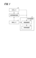
- FIG. 1 is a configuration diagram showing the connection relationship between an environment recognition device 4 according to a first embodiment of the present invention and other devices.
- the vehicle sensor 1, external sensor 2, map information providing device 3, and vehicle control device 5 are connected to the environmental recognition device 4.
- the electronic control unit (ECU: Electronic Control Unit) 6 is equipped with the environmental recognition device 4 and vehicle control device 5.
- the vehicle sensor 1, external sensor 2, map information providing device 3, environmental recognition device 4, vehicle control device 5, and electronic control device 6 are all examples of devices and sensors mounted on the same automobile. The automobile on which these devices and sensors are mounted is referred to as the "own vehicle.”
- the vehicle sensor 1 detects the state of the host vehicle, and outputs host vehicle information indicating the state of the host vehicle to the map information providing device 3 and the environment recognition device 4 .
- the external sensor 2 detects the environment around the vehicle and outputs environmental information indicating the environment around the vehicle to the map information providing device 3 and the environment recognition device 4 .
- the map information providing device 3 generates map information based on the vehicle information and environmental information, and provides the map information to the environmental recognition device 4.
- the environment recognition device 4 acquires vehicle information about the vehicle from the vehicle sensor 1, and acquires environmental information indicating the environment around the vehicle from the external sensor 2.
- the environment recognition device 4 also acquires map information from the map information providing device 3.
- the environment recognition device 4 outputs environmental information that recognizes the environment around the vehicle based on the information acquired from the vehicle sensor 1, the external sensor 2, and the environment recognition device 4 to the vehicle control device 5.
- the vehicle control device 5 controls the operation of the host vehicle based on the environmental information.
- the vehicle control device 5 executes an action plan and vehicle control for the host vehicle so that the host vehicle travels in the free space.
- the vehicle control device 5 generates a drivable area for the host vehicle based on the information on the free space, and executes an action plan and operation control for the host vehicle so that the host vehicle travels in the drivable area.
- free space refers to an area around the vehicle in which the vehicle can travel, excluding, for example, pedestrians, other vehicles, and landmarks such as pylons and fallen objects. It is also necessary to utilize free space in emergency steering avoidance from the shoulder to the curb area.
- a safe trajectory can be generated by determining the trajectory to be set for the vehicle's action plan within the free space, allowing the vehicle to travel safely. For example, if a pylon has been installed because the road is under construction, there is a high possibility that the preceding vehicle will decelerate, so the vehicle control device 5 performs an action plan so that the vehicle can also safely decelerate. Also, if the preceding vehicle is stopped, the vehicle control device 5 performs an action plan so that the vehicle can perform emergency avoidance of the preceding vehicle.
- the electronic control device 6 is provided, for example, when the environment recognition device 4 and the vehicle control device 5 are integrated as a zone ECU. Therefore, when the environment recognition device 4 and the vehicle control device 5 are not integrated, the electronic control device 6 may have a function different from that of the environment recognition device 4 and the vehicle control device 5.
- FIG. 2 is a block diagram showing an example of the internal configuration of the vehicle sensor 1, the external sensor 2, and the map information providing device 3.
- the vehicle sensor 1 is a group of sensors that detect the state of the vehicle and measures information such as vehicle speed, acceleration, angular velocity, and position information such as the latitude, longitude, and orientation of the vehicle.
- the vehicle sensor 1 includes, for example, a wheel speed sensor 11, an acceleration sensor 12, a gyro sensor 13, an IMU (Inertial Measurement Unit) 14, and a GNSS (Global Navigation Satellite System) 15.
- the wheel speed sensor 11 detects the vehicle speed based on the rotation speed of the tires of the host vehicle.
- the acceleration sensor 12 detects the acceleration of the host vehicle.
- the gyro sensor 13 detects the angular velocity of the host vehicle.
- the IMU 14 is an inertial sensor that detects the inertia of the host vehicle.
- the GNSS 15 acquires the position (latitude and longitude) and direction of the vehicle on the ground. The operation of the GNSS 15 will be described in detail later.
- the external sensor 2 is a group of sensors that detect the environment around the vehicle, and measures the positions, heights, types, etc. of surrounding objects, lane markings and road markings around the vehicle, and the positional relationship between the vehicle and other vehicles.
- the external sensor 2 includes, for example, a camera 21, a millimeter wave radar 22, an ultrasonic sensor 23, a LIDAR (Light Detection and Ranging) 24, and a V2X (Vehicle To Everything) device 25.
- V2X is the name given to connecting a vehicle to other devices and exchanging information.
- the camera 21 captures an image of the surrounding environment of the host vehicle.
- the camera 21 may be, for example, a monocular camera, a stereo camera, or a multi-camera that captures an image of the surroundings of the host vehicle.
- the millimeter wave radar 22 irradiates an object with millimeter waves in a frequency band of 30 GHz to 300 GHz, and detects the distance, angle, etc. of the object relative to the vehicle.
- the ultrasonic sensor 23 detects the distance to an object using ultrasonic waves.
- the LIDAR 24 detects the distance to an object by using pulsed laser light.
- the V2X device 25 connects equipment in the vehicle and other vehicles to transmit and receive information between them.
- the map information providing device 3 receives as input the vehicle speed, acceleration, and attitude information from the vehicle sensor 1, and position information such as latitude, longitude, and direction from the GNSS 15 included in the vehicle sensor 1.
- the attitude information is composed of information on the vehicle's traveling direction and the amount of rotation around each axis of the vehicle, and includes information on the roll angle, pitch angle, and yaw angle.
- the map information providing device 3 includes, for example, a locator 31, a map information acquisition unit 32, a map information management unit 33, and a map information DB (Data Base) 34.
- the locator 31 determines the amount of movement of the host vehicle during a processing cycle based on the wheel speed, acceleration, and attitude information acquired from the vehicle sensor 1.
- the locator 31 also estimates the position and orientation of the host vehicle on the map acquired by the map information acquisition unit 32 based on the estimated amount of movement of the host vehicle.
- the position estimated by the locator 31 may be latitude and longitude, or may be a position in a plane rectangular coordinate system.
- the map information acquisition unit 32 acquires map information corresponding to the vehicle's position based on the latitude, longitude, and direction of the vehicle acquired from the GNSS 15, and stores the map information in the map information DB 34.
- This map information is a map that includes information such as the positions of road markings painted on the road, road edges, road signs, and road markings, and the positions and heights of structures, and is called a high-precision map or a high-definition map.
- the map information management unit 33 updates or deletes the map information of the surroundings of the vehicle stored in the map information DB 34 based on the vehicle's position from the GNSS 15. For example, even if a map has been acquired once, the map information may have changed due to construction work or structural repairs, etc., so the map information management unit 33 updates the contents when new map information is acquired.
- Map information DB34 stores map information about the area around the vehicle and map information including the route to the vehicle's destination.
- Map information about the area around the vehicle includes, for example, information about buildings, viaducts, traffic lights, road signs, and markings.
- map information for points a certain distance away from the vehicle is unnecessary, and in order to prevent the storage area of the map information DB 34 from becoming overloaded, the map information management unit 33 deletes unnecessary map information from the map information DB 34.
- the map information providing device 3 outputs the position of the vehicle and map information including the positions and heights of dividing lines, road edges, road markings, road signs, structures, etc. on the road surface on which the vehicle is traveling.
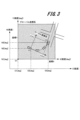
- Fig. 3 is an explanatory diagram of the functions of the GNSS 15 and the locator 31.
- a global coordinate system having an origin at a reference position of a map acquired by the map information acquisition unit 32 based on the latitude and longitude of the vehicle acquired from the GNSS 15, and a local coordinate system having the vehicle as a reference are shown superimposed on each other.
- the coordinates of the map acquired from the map information acquisition unit 32 are expressed as a coordinate system with E on the horizontal axis and N on the vertical axis.
- the horizontal axis E is in longitude [deg]
- the vertical axis N is in latitude [deg].
- Point O1 on the map is the origin coordinate of the map, and is identified by the coordinates (E1, N1).
- the coordinates at the time of starting the host vehicle acquired from the GNSS 15 become the reference point for identifying the coordinates of the host vehicle as it moves thereafter. Therefore, the coordinates at the time of starting the host vehicle correspond to point O2 in the figure, and are identified by the coordinates (E2, N2).
- the coordinates of the host vehicle also change as the host vehicle travels. As shown in the figure, the current coordinates at the destination where the host vehicle has turned left correspond to point O3 in the figure, and are identified by the coordinates (E3, N3).
- global coordinates are expressed with X on the horizontal axis and Y on the vertical axis.
- the horizontal axis X is in longitude [deg]
- the vertical axis Y is in latitude [deg].
- the rectangular area of the global coordinates, hatched in the figure, represents the map acquired by the map information acquisition unit 32 based on the position information acquired from the GNSS 15 of the vehicle.
- point O1 in the figure is also the reference position (i.e. the origin) of the map.
- the current coordinates of the destination where the vehicle has turned left correspond to point O3 in the figure, and are identified by the coordinates (E3, N3).
- Local coordinates are expressed as coordinates with x on the horizontal axis and y on the vertical axis.
- the unit of the horizontal axis x is [m]
- the unit of the vertical axis y is [m].
- the locator 31 calculates the amount of movement from a certain reference position based on the speed, acceleration, and attitude of the host vehicle, and the position and orientation of the GNSS 15. For example, the locator 31 calculates the amount of movement between processing (control) cycles of the host vehicle, and the total amount of movement since the host vehicle was turned on.
- the locator 31 is mainly used to determine the amount of movement of the vehicle in an environment where GNSS 15 cannot be acquired. For example, the locator 31 estimates the amount of movement [m] of the vehicle in a situation where satellite radio waves cannot reach, such as in a tunnel or underground, and also estimates the amount of movement [m] of the vehicle (for example, processing period of about 50 ms) between GNSS 15 reception cycles (typically 1 second cycles).
- the map information management unit 33 converts the amount of movement [m] to the amount of movement [deg] using the Hubeny formula or the like, matches it to the latitude, longitude, and direction of the vehicle, and determines the position (latitude, longitude) and direction on the ground.
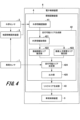
- FIG. 4 is a block diagram showing an example of the internal configuration of the environment recognition device 4 according to the first embodiment.
- the environment recognition device 4 is composed of an external information recognition unit 41, a drivable area generation unit 42, and a risk area generation unit 43.
- the external environment information recognition unit 41 is provided in the environment recognition device 4, and acquires environmental information indicating the environment around the vehicle from the external environment sensor 2, acquires map information from the map information providing device 3, and recognizes the external environment information based on the acquired environmental information and map information.
- the external environment information recognition unit 41 acquires, as the environmental information, for example, the position, height, type, etc. of objects around the vehicle detected by the external environment sensor 2, the division lines and road markings painted on the road surface, the position and height of the road edge, the type of the road edge, roadside objects such as road signs installed on the traveling road surface, and drivable area information excluding the positions of obstacles around the vehicle.
- the external environment sensor 2 itself can detect the drivable area (so-called free space information).
- the external environment information recognition unit 41 acquires the speed, acceleration, attitude information, etc. of the vehicle from the external environment sensor 2 as observation information. Furthermore, the external environment information recognition unit 41 acquires map information from the map information providing device 3, such as information on the position (latitude and longitude, etc.) and direction of the vehicle.
- the external environment information recognition unit 41 also has functions such as semantic segmentation, which recognizes groups of pixels that form characteristic categories (people, vehicles, traffic signs, road structures, etc.) in the images of the surroundings of the vehicle detected by the camera 21 (see Figure 2) of the external environment sensor 2. The external environment information recognition unit 41 then acquires the position and height information of the contours of the recognized objects.
- semantic segmentation which recognizes groups of pixels that form characteristic categories (people, vehicles, traffic signs, road structures, etc.) in the images of the surroundings of the vehicle detected by the camera 21 (see Figure 2) of the external environment sensor 2.
- the external environment information recognition unit 41 then acquires the position and height information of the contours of the recognized objects.
- the external information recognition unit 41 can integrate information that is considered to be identical among the observation information that can be obtained from multiple sensors (camera 21, millimeter wave radar 22, ultrasonic sensor 23, LIDAR 24, V2X device 25, etc.), identify the position, size, and type of objects around the vehicle based on the integrated information, and output the recognition results.
- the drivable area generating unit 42 generates a drivable area excluding obstacles around the vehicle.
- This drivable area generating unit 42 is composed of an external environment information acquiring unit 421, a road surface obstacle area estimating unit 422, an above road surface obstacle area estimating unit 423, a drivable area determining unit 424, and an output unit 425.
- the external environment information acquisition unit acquires external environment information including two-dimensional or three-dimensional information of objects existing around the vehicle from an external environment sensor mounted on the vehicle.
- the external environment information acquisition unit 421 acquires the external environment information recognized by the external environment information recognition unit 41.
- an initial drivable area is generated from the external environment information.
- the road surface obstacle area estimation unit recognizes road surface obstacles present on the road surface of the road on which the vehicle is traveling based on external environment information, and estimates the road surface obstacle area.
- the road surface obstacle area estimation unit acquires the position of the road surface obstacle and estimates the road surface obstacle area.
- Road surface obstacles around the vehicle include, for example, objects such as pylons, fallen objects, people, or other vehicles that are in contact with the road surface around the vehicle.
- Road surface obstacles also include, for example, parts of the road surface that have collapsed, and obstacles that exist below the road surface, such as a port embankment.
- the above-road obstacle area estimation unit (above-road obstacle area estimation unit 423) recognizes obstacles above the road surface that are located above the road surface and are spaced apart from the traveling road surface based on external information, and estimates the above-road obstacle area.
- the above-road obstacle area estimation unit (above-road obstacle area estimation unit 423) estimates the above-road obstacle area based on information on the position and height of the obstacle above the road surface.
- Examples of above-road obstacles include structures that exist above the road surface, such as tunnels, viaducts, speed limit bars at toll booths, and roadside tree branches.
- the drivable area determination unit determines a drivable area in which the vehicle can travel, based on the road surface obstacle area and the obstacle area above the road surface.
- the drivable area determination unit determines, as the drivable area, an area obtained by excluding the road surface obstacle area and the obstacle area above the road surface from the initial drivable area detected by the external sensor. Then, the drivable area determination unit (drivable area determination unit 424) assigns areas of the road obstacle area that the vehicle can overcome or enter as drivable areas based on at least one of the vehicle's driving condition and height information of the road obstacle.
- the drivable area is determined using vehicle information acquired from the vehicle sensor 1.
- the drivable area determination unit 424 determines the drivable area as the initial drivable area generated from the vehicle information and external environment information, excluding road surface obstacles and obstacles above the road surface.
- the drivable area is the portion excluding various obstacles, and may be expressed in a format such as OGM (Occupancy Grid Map), in which the road surface is divided into a grid and the probability of the existence of an obstacle is assigned to each cell.
- OGM Olecupancy Grid Map
- the drivable area in this embodiment is expressed as information in which the boundaries of detected obstacles are connected by lines.
- the output unit outputs the drivable area to a vehicle control device that controls the behavior of the vehicle.
- the output unit 425 outputs the drivable area determined by the drivable area determination unit 424 to the risk area generation unit 43.
- the risk area generating unit (risk area generating unit 43) generates risk area information indicating the driving danger level around the vehicle as a risk area based on the driveable area output from the output unit (output unit 425) and external information, and superimposes the risk area on the driveable area.
- the risk area generating unit 43 generates risk area information indicating the driving danger level around the vehicle as a risk area based on the driveable area output from the output unit 425 and information on objects detected by the external sensor 2.
- the risk area generating unit 43 may consider places other than the driveable area as risk areas.
- there are risks such as clearly imaginable risks around objects around the vehicle and risks of invisible blind spots around objects, as well as risks in side strips and oncoming lanes.
- the risk area generating unit 43 may set risk values in stages for each risk area. For example, an index such as risk 1 (driving possible in an emergency, such as a side strip) and risk 2 (absolutely not allowed, such as an oncoming lane) may be set as a risk value for each risk area.
- the risk area generation unit 43 superimposes the risk area information on the drivable area determined by the drivable area determination unit 424, and outputs the drivable area information to the vehicle control device 5.
- the vehicle control device (vehicle control device 5) generates a trajectory for the vehicle to travel based on the drivable area, and controls the vehicle's travel by performing trajectory tracking control for the vehicle to follow the trajectory.
- the vehicle control device 5 generates a trajectory along which the vehicle can travel safely based on the drivable area and risk area information acquired from the risk area generation unit 43, and performs trajectory tracking control according to the trajectory. For this reason, the vehicle control device 5 receives the position, attitude information, speed information, acceleration information, drivable area and risk information around the vehicle from the environment recognition device 4, outputs drive control signals, braking control signals, and steering control signals, and controls the vehicle's travel.
- the vehicle control device 5 may also control the vehicle's travel by receiving only the drivable area output from the output unit 425 as input, without going through the risk area generation unit 43.
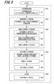
- FIG. 5 is a flowchart showing a process of generating a travelable area according to the first embodiment.
- the travelable area determination method will be explained with reference to drawings showing an example of generating a travelable area.
- the external information acquisition unit 421 of the drivable area generation unit 42 acquires external information from the external information recognition unit 41 (S1).
- the external information acquired by the external information acquisition unit 421 includes, for example, object information (including object position, object height, object type, and structures above the road surface) around the vehicle detected by the external sensor 2 such as the camera 21, millimeter wave radar 22, and LIDAR 24, and demarcation line information (demarcation line position, line color, and line type such as dashed line and solid line).
- Other external information includes, for example, road edge information (position and height of road edge), map information (lane information of the travel route (forward and reverse direction information of the lane), road signs installed on the travel route, road markings on the travel road surface, and the position of construction or traffic restriction sections), and the initial drivable area output by the external sensor 2. Furthermore, if the external information acquisition unit 421 cannot acquire external information from the external sensor 2, it may use the lane marking information and road edge information included in the map information provided by the map information providing device 3.
- host vehicle E the automobile equipped with the environment recognition device 4 will be referred to as "host vehicle E.”
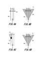
- FIG. 6A is a diagram showing an example of a driving environment of the host vehicle E.
- a road end RE (Road End) exists on the left side of the road on which the vehicle E runs (hereinafter referred to as the "running path").
- the road has three lanes, and the two lanes on the left side are forward lanes, and the lane on the right side is an oncoming lane.
- a road end RE also exists on the right side of the road on which the vehicle E runs, but is not shown.
- An upper object UO Upper object
- UO a height-restricted gate whose height is less than the vehicle height of the vehicle E is assumed.
- the running scenario represents that the vehicle E runs toward a structure UO installed on the upper part of the running path.
- the structure UO existing above the running road surface includes a structure with a height restriction such as a tunnel or an elevated bridge, as well as a structure that moves up and down and has a gate support installed on the running road surface.
- FIG. 6B is a diagram showing an example of the initial travelable area F1 acquired by the external environment information acquisition unit 421.
- the initial travelable area F1 is information recognized by the external sensor 2 in the external information recognition unit 41.
- This initial travelable area F1 may be a combination of travelable areas detected by multiple sensors, or may utilize a travelable area detected by a single sensor.
- the external sensor 2 will recognize the structure UO as the initial travelable area F1 even if it is an elevated bridge or gate bar that is too high for the host vehicle E to pass through.
- the road surface obstacle area estimation unit 422 acquires the position of an object LO (Lower object) that is in contact with the road surface (S2 in FIG. 5), and sets a road surface obstacle area F2.
- an object LO Lower object
- the road surface obstacle area F2 will be described with reference to FIG. 6C.
- 6C is a diagram showing an example of a road surface obstacle area F2 set on a road, where an object LO is present.
- the road obstacle area F2 is generated so that the drivable area generating unit 42 can generate a drivable area in a later process if the external sensor 2 does not detect the initial drivable area F1.
- the road obstacle area estimating unit 422 generates the blind spot behind an object as seen from the vehicle E, for example, the blind spot of the object LO, as the road obstacle area F2.
- FIG. 6D is a diagram showing an example of the initial drivable area F1 with the road obstacle area F2 removed.
- sensors do not detect objects above the road surface, so they output an area excluding objects in contact with the road surface as the initial drivable area F1.
- the sensor that detects the drivable area detects only the support pillars (the circular end portions on the left and right) of the structure UO as obstacles. Meanwhile, there is space below the central portion of the structure UO. For this reason, the sensor that detects the drivable area outputs the area excluding the support pillars of the structure UO, and also the area behind the structure UO as seen from the vehicle, as the initial drivable area F1.
- the above-road obstacle area estimation unit 423 in this embodiment estimates an obstacle area above the road surface. For this reason, the above-road obstacle area estimation unit 423 does not determine a road obstacle for an object LO that is in contact with the road surface estimated by the road obstacle area estimation unit 422, but determines whether the vehicle can pass under a structure UO that exists above the road surface. The above-road obstacle area estimation unit 423 then determines whether or not to generate an above-road obstacle area.
- the above-road obstacle area estimation unit 423 determines whether or not to generate an above-road obstacle area, information on the position and height of the structure UO is required. Therefore, the above-road obstacle area estimation unit 423 acquires the position and height of the contour part of the structure UO that exists above the road surface (S3). In the second embodiment described later, in addition to the position and height of the contour part of the structure UO, information on the type of the structure UO is also acquired.
- the road surface above obstacle area estimation unit 423 regards the portion of the contour of the structure UO that is surrounded by the inner contour of the structure UO and the road surface as the contour UOL (Upper Object Line). At the same time, it generates a contour BL (Base Line) 1 (see Figures 7A and 7B) when the host vehicle E is viewed from the front.
- the contour BL1 of the host vehicle E and the contour UOL of the structure UO will be explained with reference to Figures 7A and 7B.
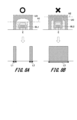
- FIG. 7A is a diagram showing an example of a contour BL1 of the host vehicle E.
- the contour BL1 is set according to the width and height H1 of the host vehicle E.
- the width and height H1 of the host vehicle E are specified values for each vehicle model, so the road surface above obstacle area estimation unit 423 can acquire the width and height H1 of the host vehicle E in advance.
- the host vehicle E is a truck with a loading platform
- the height H1 of the host vehicle E may be greater than the specified value depending on the height of the load on the loading platform.
- the host vehicle E may sink due to the weight of the load on the loading platform, and the height H1 may be lowered.
- the host vehicle E has a vehicle height adjustment function, it is assumed that the height H1 may differ depending on the usage situation of the host vehicle E.
- the height H1 of the host vehicle E may be set in the environment recognition device 4 according to the setting state of the vehicle height adjustment function of the host vehicle E.
- the driver of the host vehicle E may take a picture of the host vehicle E with a camera provided on a mobile terminal before getting in and transfer the taken image to the environment recognition device 4.
- the above-road obstacle area estimation unit 423 of the environment recognition device 4 can set the height H1 of the host vehicle E based on the image sent from the camera of the mobile terminal.
- the driver of the host vehicle E may input and set the height H1 of the host vehicle E in advance from an operation panel in the driver's seat or a mobile terminal. This setting enables the above-road obstacle area estimation unit 423 to accurately estimate whether or not the height of an obstacle above the road surface interferes with the height of the host vehicle E.
- FIG. 7B is a diagram showing an example of an outline UOL of a structure UO.
- the above-road obstacle area estimation unit 423 generates the lower contour UOL of the structure UO from the contour of the structure UO. Then, the above-road obstacle area estimation unit 423 performs collision determination between the contour of the obstacle above the road surface and the contour of the vehicle E (S4 in FIG. 5). That is, the above-road obstacle area estimation unit 423 determines whether the vehicle E can enter inside the structure UO, i.e., the contour UOL.
- the above road obstacle area estimation unit 423 moves the contour BL1 of the host vehicle E laterally along the road surface relative to the contour UOL, and determines whether the contour BL1 of the host vehicle E can be contained between the contour UOL and the road surface. Other methods may be used to determine whether the contour BL1 of the host vehicle E fits inside the structure UO. If the above road obstacle area estimation unit 423 determines that the host vehicle E has hit the contour UOL of the structure UO, the host vehicle E cannot pass under the structure UO. If the above road obstacle area estimation unit 423 determines that the host vehicle E has not hit the contour UOL of the structure UO, the host vehicle E can pass under the structure UO.
- FIG. 8A is a diagram showing an example in which the contour BL1 of the host vehicle E does not contact the contour UOL.
- the road surface above obstacle area estimation unit 423 judges that the contour BL1 of the host vehicle E can be contained within the contour UOL without contacting it.
- the road surface above obstacle area estimation unit 423 generates line segments L1 and L2 that are located in the lateral direction of the traveling road surface and where the support pillars of the structure UO and the road surface meet. Note that a circle is attached to the upper part of Fig. 8A to indicate that the host vehicle E can pass under the structure UO.
- FIG. 8B is a diagram showing an example in which the contour BL1 of the host vehicle E comes into contact with the contour UOL.
- the road surface above obstacle area estimation unit 423 determines that the contour BL1 of the vehicle E comes into contact with the contour UOL and cannot be contained therein.
- the road surface above obstacle area estimation unit 423 surrounds the outer shape of the structure UO with a polygon, and generates the portion where this polygon comes into contact with the road surface as a line segment L3. Note that a cross is marked at the top of Fig. 8B to indicate that the vehicle E cannot pass under the structure UO.
- FIG. 9 is a diagram showing an example of an initial travelable area detected by a plurality of sensors.
- the external sensor 2 includes a plurality of types of sensors.
- the detectable distance of the travelable area that each sensor can detect varies depending on the type of sensor.
- the range of an initial travelable area F3 that a certain sensor can detect is different from the range of an initial travelable area F4 that another sensor can detect.
- the distance D1 in the depth direction at which a certain sensor can detect the initial drivable area F3 is shorter than the distance D2 in the depth direction at which another sensor can detect the initial drivable area F4. Therefore, in consideration of safety, the obstacle area above road surface estimation unit 423 adopts the distance D1 that can be detected by the sensor with the shortest distance of the drivable area among the sensors mounted on the host vehicle E that can detect the drivable area. The obstacle area above road surface estimation unit 423 then recognizes the overlapping portion of the initial drivable areas F3 and F4 as an area with high reliability, and makes it possible to use this area to generate the obstacle area above the road surface. However, when the host vehicle E is traveling at high speed, the distance D2 that can be detected by the sensor of the host vehicle E with the longest detectable distance may be adopted to detect obstacles above the road surface that exist within the range of distance D2.
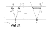
- FIG. 10 is a diagram showing an example of an obstacle area F5 above the road surface.
- the above road obstacle area estimation unit 423 when the contour BL1 of the host vehicle E does not contact the contour UOL, the above road obstacle area estimation unit 423 generates the blind spot of the line segments L1 and L2 as seen from the host vehicle E as an above road obstacle area F5.
- the above road obstacle area estimation unit 423 when the contour BL1 of the host vehicle E contacts the contour UOL, the above road obstacle area estimation unit 423 generates the blind spot of the line segment L3 as seen from the host vehicle E as an above road obstacle area F5.
- the obstacle area above road surface estimation unit 423 sets a straight line connecting the center of the vehicle E to both ends of line segments L1 and L2, and a straight line L4 at a point a distance D1 in front of the vehicle from the center of the vehicle E so as to be parallel to the y-axis of the vehicle E.
- the obstacle area above road surface estimation unit 423 then generates the area surrounded by each straight line and line segments L1 and L2 as the obstacle area above road surface F5.
- the obstacle area above road surface estimation unit 423 generates the area surrounded by the straight lines connecting the center of the vehicle E to both ends of line segment L3, the set straight line L4, and line segment L3 as the obstacle area above road surface F5.
- the above road obstacle area estimation unit 423 judges only the pillars of the structure UO to be obstacles (see FIG. 8A), it generates an above road obstacle area F5 as shown on the left side of FIG. 10.
- the above road obstacle area estimation unit 423 generates an above road obstacle area F5 as shown on the right side of FIG. 10 (S5).
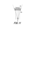
- FIG. 11 is a diagram showing an example of an obstacle area F5 above the road surface, which indicates that the host vehicle E cannot pass through.
- the above-road obstacle area estimation unit 423 determines that the vehicle E cannot pass under the structure UO, it sets an above-road obstacle area F5 over the entire road as shown in Fig. 11. This allows the vehicle E to stop in front of the structure UO.
- the above-road obstacle area estimation unit 423 determines that the vehicle E can pass under the structure UO, it is unclear whether the vehicle E can actually travel in drivable areas other than the above-road obstacle area F5 (for example, areas outside the road edge RE). For example, when the vehicle E is traveling normally, it is necessary to ensure that the vehicle E does not travel outside the road or into the oncoming lane. Therefore, returning to FIG. 5, we will continue to explain the process in which the drivable area determination unit 424 determines whether the drivable area detected by the external sensor 2 is actually drivable.
- the drivable area determination unit 424 determines the area in which the host vehicle E can travel. To this end, the drivable area determination unit 424 uses road edge information present on the travel road to obtain the position and height of the road edge RE on the travel road surface, and limits the drivable area (S6). In other words, the drivable area determination unit 424 resets the range of the drivable area.
- the road edge information includes information on the position and height of the road edge RE, information on the oncoming lane, etc.
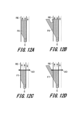
- FIG. 12A is a diagram showing an example of a drivable area F6 that is restricted to only the forward lane.
- the drivable area determination unit 424 uses road edge information to limit the drivable area F6 to only the lanes in the forward direction that include the lane in which the host vehicle E is traveling.
- the drivable area F6 shown in FIG 12A is for normal traveling, and does not include areas outside the road edge RE so that the host vehicle E cannot move outside the road edge RE.
- FIG. 12B is a diagram showing an example of a drivable area F6 that includes areas outside the roadway.
- the drivable area determination unit 424 determines a drivable area F6 including the outside of the roadway so that the vehicle E can evacuate to the outside of the roadway such as a sidewalk only when it is determined that the vehicle E can travel safely and without harming the surroundings.
- the outside of the roadway includes, for example, a sidewalk, a road shoulder, a waiting area, etc.
- the drivable area F6 is set so that the vehicle E does not travel in the oncoming lane.
- the drivable area F6 shown in FIG. 12B is for emergency driving, and includes an area outside the roadside RE so that the vehicle E can evacuate to the outside of the roadside RE depending on the situation.
- the drivable area determination unit 424 may set the height of the road edge RE by referring to the height of the "vehicle access portion" of the curb as specified in the Road Structure Ordinance of Japan.
- the drivable area determination unit 424 acquires two types of obstacle areas generated by the road surface obstacle area estimation unit 422 and the road surface upper obstacle area estimation unit 423 (S7 in FIG. 5). That is, the drivable area determination unit 424 acquires the road surface obstacle area F2 generated by the road surface obstacle area estimation unit 422 and the road surface upper obstacle area F5 generated by the road surface upper obstacle area estimation unit 423.
- the drivable area determination unit 424 uses the obstacle areas obtained from each estimation unit to modify the drivable area detected by the external sensor 2. For example, the drivable area determination unit 424 determines the final drivable area F7 by removing the obstacle areas obtained from each estimation unit from the drivable area reset in step S6 (S8).
- FIG. 12C is a diagram showing an example of a drivable area F7 during normal driving.
- driving is restricted to areas other than the roadway, and the host vehicle E cannot pass under the structure UO, so driving is restricted by the structure UO. For this reason, the host vehicle E is controlled to stop within the drivable area F7.
- FIG. 12D is a diagram showing an example of a drivable area F7 in the case of emergency driving.
- driving is restricted on areas other than the roadway, and the host vehicle E cannot pass under the structure UO, so driving is restricted by the structure UO.
- the area into which the host vehicle E can retreat includes areas outside the roadside RE. For this reason, the host vehicle E may be controlled to retreat to an area outside the roadside RE. If the vehicle speed of the host vehicle E is high, there is a risk that the host vehicle E will lose control when it passes the roadside RE. For this reason, even during emergency driving, the drivable area F7 during normal driving shown in FIG. 12C may be determined depending on the vehicle speed of the host vehicle E.
- the output unit 425 outputs the drivable area F7 determined by the drivable area determination unit 424 to the risk area generation unit 43 (S9).
- the risk area generation unit 43 generates a risk area based on the drivable area F7 and the information on the object detected by the external sensor 2.
- the vehicle control device 5 performs driving control of the vehicle E based on the information on the drivable area and the risk area.
- the process returns to step S1 again, and the processing is executed in a loop again.
- the reason for the loop in this manner is that, for example, driving through an ETC gate is assumed.
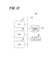
- Fig. 13 is a block diagram showing an example of a hardware configuration of the calculator 50.
- the calculator 50 is an example of hardware used as a computer capable of operating as the environment recognition device 4 according to the present embodiment.
- the environment recognition device 4 according to the present embodiment realizes a method of determining a drivable area performed by the respective functional blocks shown in Fig. 4 in cooperation with each other by the calculator 50 (computer) executing a program.
- Computer 50 includes a CPU (Central Processing Unit) 51, a ROM (Read Only Memory) 52, and a RAM (Random Access Memory) 53, each of which is connected to a bus 54. Furthermore, computer 50 includes non-volatile storage 55 and a network interface 56.
- CPU Central Processing Unit
- ROM Read Only Memory
- RAM Random Access Memory
- the CPU 51 reads out the program code of the software that realizes each function of this embodiment from the ROM 52, loads it into the RAM 53, and executes it. Variables, parameters, etc. that arise during the calculation processing of the CPU 51 are temporarily written to the RAM 53, and these variables, parameters, etc. are read out by the CPU 51 as appropriate.
- a GPU Graphics Processing Unit
- the CPU 51 and the GPU Graphics Processing Unit
- the non-volatile storage 55 may be, for example, a hard disk drive (HDD), solid state drive (SSD), flexible disk, optical disk, magneto-optical disk, CD-ROM, CD-R, magnetic tape, or non-volatile memory.
- HDD hard disk drive
- SSD solid state drive
- this non-volatile storage 55 records programs for operating the computer 50.
- the ROM 52 and non-volatile storage 55 record programs, data, etc. necessary for the CPU 51 to operate, and are used as an example of a computer-readable, non-transitory storage medium that stores programs executed by the computer 50.
- the network interface 56 may be, for example, a NIC (Network Interface Card), and various types of data can be sent and received between devices via a LAN (Local Area Network) or dedicated line connected to the NIC terminal.
- NIC Network Interface Card
- the road surface obstacle areas and obstacle areas above the road surface are removed from the drivable area detected by the external sensor 2 to determine the drivable area.
- the drivable area determination unit 424 can generate a drivable area that takes into account not only structures that exist adjacent to the road surface, but also structures that exist above the road surface. In this way, the drivable area generation unit 42 can generate a more realistic drivable area than before, and the vehicle control device 5 realizes safe vehicle control so that the vehicle can drive in the drivable area.
- the environment recognition device 4 also considers the height of the vehicle and restricts driving to structures with height restrictions or no-entry areas. This makes it possible to prevent the vehicle from erroneously entering areas with height restrictions or no-entry areas during autonomous driving. Even if the vehicle activates the AES and performs emergency driving, it is possible to steer the vehicle to avoid structures.
- different ranges of the drivable area F7 can be set depending on whether the vehicle E is driving normally or in an emergency. Therefore, during emergency driving, the vehicle E is more likely to be able to stop safely or avoid the structure UO.
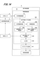
- FIG. 14 is a block diagram showing an example of the internal configuration of an environment recognition device 4A according to the second embodiment.
- the environment recognition device 4A includes a failure identification unit 426 in addition to the respective functional units included in the environment recognition device 4 according to the first embodiment shown in FIG.
- the obstacle identification unit (obstacle identification unit 426) outputs an obstacle identification result that identifies the type or material of a location identified as a road surface obstacle or an obstacle above the road surface based on the external environment information. For this reason, the obstacle identification unit 426 has learning data in which the type or material of a structure is learned in advance for each type of structure.
- the obstacle identification unit 426 uses the learning data to acquire detection results of obstacles such as structures in the drivable area from the external environment sensor 2 (e.g., a camera sensor) and identifies the type or material of the obstacle.
- the "type” is, for example, a curb or a bar in a parking lot
- the “material” is, for example, concrete that makes up the curb, a rubber material that covers the bar and is not damaged even if a car comes into contact with it, etc.
- the obstacle identification unit 426 may be configured to improve the type identification accuracy when the host vehicle travels on a road where similar structures exist by acquiring the results of identification of the types of various structures by the environment recognition device 4 of the other vehicle from the V2X device 25 shown in FIG. 2.
- the obstacle identification unit 426 attaches the identified type or material information to the structure in the drivable area identified by the external sensor 2, and outputs the information to the road surface obstacle area estimation unit 422 and the road above obstacle area estimation unit 423.
- the road obstacle area estimation unit (road obstacle area estimation unit 422) estimates the road obstacle area based on the obstacle identification result. At this time, the road obstacle area estimation unit 422 generates the road obstacle area based on the structures in the drivable area identified by the external sensor 2 and information on the type or material.
- the obstacle area above the road surface estimation unit (obstacle area above the road surface estimation unit 423) estimates an obstacle area above the road surface based on the obstacle identification result.
- the obstacle area above the road surface estimation unit 423 generates an obstacle area above the road surface based on information on the type or material of structures in the drivable area identified by the external sensor 2.
- the drivable area determination unit assigns areas of the road obstacle area that the vehicle can overcome or enter as drivable areas based on at least one of the vehicle's driving state, road obstacle height information, and obstacle identification results. For example, even if a tree branch protrudes into the driving path, if the obstacle above the road surface is merely a leaf or a thin branch, there is no hindrance to driving even if the vehicle comes into contact with it. Also, if rainwater is falling from the eaves of a building, there is no hindrance to driving even if the vehicle comes into contact with the rainwater. In such cases, the type of the obstacle above the road surface is identified as "leaf" or "rainwater,” and the drivable area is determined as an obstacle above the road surface that does not hinder driving.
- the road surface obstacle area estimation unit 422 and the road surface above obstacle area estimation unit 423 can appropriately estimate road surface obstacles and obstacles above the road surface based on the information on the type or material of the obstacle, and generate a road surface obstacle area and an above road surface obstacle area.
- FIG. 15 is a block diagram showing an example of the internal configuration of an environment recognition device 4B according to the third embodiment.
- the environment recognition device 4B includes a travel-restricted area estimation unit 427 in addition to the functional units included in the environment recognition device 4 according to the first embodiment shown in FIG.
- the travel-prohibited area estimation unit (travel-prohibited area estimation unit 427) estimates a travel-prohibited area in which the vehicle is prohibited from traveling, based on signs or markings on the road on which the vehicle travels.
- the travel-prohibited area estimation unit 427 can estimate a travel-prohibited area based on the external environment information acquired by the external environment information acquisition unit 421 by acquiring map information from the map information providing device 3.
- No-travel areas include areas specified by road signs or road markings that prohibit entry as stipulated by law, etc. There are also areas where automobiles are prohibited from traveling at certain times. For example, there are areas where general vehicles are prohibited from traveling during certain times of the day, such as bus routes or school routes. In such areas where traveling is prohibited, the time period is displayed on the signs. For this reason, the no-travel area estimation unit 427 can recognize the time periods when traveling is prohibited based on images of the signs captured by the external sensor 2 (e.g., a camera), and estimate the no-travel area during those times.
- the external sensor 2 e.g., a camera
- roads with grade separations such as underpasses are usually at a height that allows automobiles to pass through and have no obstacles below.
- the external environment information acquisition unit 421 acquires weather information, text information from electronic bulletin boards installed beside the road, and the like as external environment information, and outputs this information to the travel-prohibited area estimation unit 427.
- the travel-prohibited area estimation unit 427 estimates the travel-prohibited area based on this information. Thereafter, the travelable area determination unit (travelable area determination unit 424) determines the area obtained by excluding the travel-prohibited areas from the initial travelable area as the travelable area.
- the no-travel area estimation unit 427 estimates the no-travel area.
- a no-travel area is an area in which a vehicle is prohibited from traveling, even if there are no obstacles on the road surface or above the road surface.
- the drivable area determination unit 424 can determine the drivable area by taking into account information on the drivable area. As a result, the vehicle control device 5 can safely control the traveling of the vehicle.
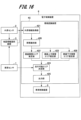
- FIG. 16 is a block diagram showing an example of the internal configuration of an environment recognition device 4C according to the fourth embodiment.
- the environment recognition device 4C is configured to include all the functional units of the environment recognition devices 4, 4A, and 4B according to the first to third embodiments, and also includes a road surface below obstacle area estimation unit 428. That is, the environment recognition device 4C includes an obstacle identification unit 426 and a road surface below obstacle area estimation unit 428 in addition to the functional units included in the environment recognition device 4 according to the first embodiment shown in FIG. 4.
- the road surface below obstacle area estimation unit (road surface below obstacle area estimation unit 428) recognizes obstacles below the road surface that exist below the road surface around the road surface based on external information, and estimates the road surface below obstacle area.
- the road surface below obstacle area estimation unit 428 has a function of recognizing an object below a certain height that is placed on the road surface as an obstacle below the road surface. For example, if a fallen object with a height of 50 cm or less exists on the road surface, the vehicle must stop in front of the fallen object or drive while avoiding the fallen object. Therefore, by generating the road surface below obstacle area by the road surface below obstacle area estimation unit 428, the drivable area determination unit 424 can determine the area excluding the road surface below obstacle area as the drivable area.
- the road surface below obstacle area estimation unit 428 estimates the road surface below obstacle area, and the vehicle control device 5 controls the traveling of the host vehicle so that the host vehicle does not come into contact with the road surface obstacle. Therefore, the vehicle control device 5 can safely control the traveling of the automobile.
- the environment recognition device 4C may be configured to further include a prohibited driving area estimation unit 427 according to the third embodiment.
- the drivable area determination unit 424 can determine areas excluding road obstacle areas, obstacle areas above the road surface, obstacle areas below the road surface, and prohibited driving areas as drivable areas.
- the present invention is not limited to the above-described embodiments, and it goes without saying that various other applications and modifications are possible without departing from the gist of the present invention as set forth in the claims.
- the above-mentioned embodiments have been described in detail and specifically to explain the configuration of the device in an easy-to-understand manner, and are not necessarily limited to those having all of the configurations described.
- it is possible to replace a part of the configuration according to the embodiment described here with a configuration according to another embodiment and it is also possible to add a configuration according to another embodiment to a configuration according to a certain embodiment.
- the control lines and information lines shown are those that are considered necessary for the explanation, and not all control lines and information lines in the product are necessarily shown. In reality, it can be considered that almost all components are connected to each other.
Landscapes
- Engineering & Computer Science (AREA)
- Automation & Control Theory (AREA)
- Transportation (AREA)
- Mechanical Engineering (AREA)
- Physics & Mathematics (AREA)
- Mathematical Physics (AREA)
- Human Computer Interaction (AREA)
- General Physics & Mathematics (AREA)
- Traffic Control Systems (AREA)
Abstract
環境認識装置は、車両に搭載された外界センサから車両の周辺に存在する物体の2次元情報又は3次元情報を含む外界情報を取得する外界情報取得部と、外界情報に基づいて、車両が走行する走行路の走行路面に存在する路面障害を認識して、路面障害エリアを推定する路面障害エリア推定部と、外界情報に基づいて、走行路面から離間した路面上方に存在する路面上方障害を認識して、路面上方障害エリアを推定する路面上方障害エリア推定部と、路面障害エリア及び路面上方障害エリアに基づいて、車両が走行可能な走行可能エリアを決定する走行可能エリア決定部と、走行可能エリアを、車両の挙動を制御する車両制御装置に出力する出力部と、を備える。
Description
本発明は、環境認識装置、走行可能エリア決定方法及び電子制御装置に関する。
近年、車両の快適で安全な運転支援や自動運転を実現するため、自車両周辺の走行環境を把握する技術が開発されている。例えば、カメラやミリ波レーダ、超音波やLIDAR(Light Detection and Ranging)といったセンサを用いた歩行者や他車両などの物体の認識結果に基づいて、衝突警報や自動ブレーキが実施される。また、路面にペイントされた区画線や道路標示、あるいは道路標識などの走行規制内容を読み取り、車線逸脱警報や車線維持を実現している。
このような安全機能の一つとして、走行路面の中で自車両の走行の障害となる領域以外を走行可能なエリアとして表現した走行可能エリア認識技術が求められている。この走行可能エリア情報を用いることで、自車両周辺の障害を安全に回避するためのリスク計算を実施することができ、安全な軌道を生成し回避行動をとることができる。走行可能エリア情報は基本的に自車両の走行路面に接する障害物について考慮されているが、路面上方に存在する障害物についても考慮して生成する必要があった。これについて、以下の特許文献1及び2に記載された技術が提案されている。
特許文献1には、「車両制御システムは、車両周辺の空間に存在し路面から離れた障害物を検出する検出部と、検出部により検出された障害物の大きさまたは種別の少なくとも一方を推定し、障害物の大きさまたは種別の少なくとも一方の推定結果に基づき障害物の挙動を予測し、障害物の挙動の予測結果に基づき車両の危険回避行動計画を生成する行動計画生成部と、を備える。」と記載されている。
特許文献2には、「自律走行装置は、距離情報を含む周辺情報を取得する情報取得部と、情報取得部から取得した周辺情報に基づいて、路面領域と進路空間領域とを設定する領域設定部と、領域設定部によって設定された路面領域における周辺情報をもとに、路面上の進行可能性を判定する路面領域判定部と、進路空間領域における周辺情報をもとに、経路上の障害物を判定する障害物判定部と、路面領域判定部および障害物判定部によって判定された判定結果に基づいて進行の可否を決定する進行可否決定部と、を有する。」と記載されている。
自車両が安全に走行するためには走行路面に存在する障害物に対するリスクを正しく判断できることが重要となる。例えば、自車両がAES(Autonomous Emergency Steering)発動時であっても、障害物があれば安全に自車両が走行又は停止することが求められる。
特許文献1に記載された技術では、路面から離れて存在する障害物の挙動から直接的に回避することの必要性が求められている。しかしながら、安全な回避行動をとるためにはリスク計算が不可欠であり、リスク計算を行うためには走行可能エリアの生成が必要となる。また、特許文献2に記載された技術では、進路空間領域の物体を検知し障害物と判定しているが、自車両が障害物の下方を通り抜けられるかどうかの判断が必要となる。
本発明はこのような状況に鑑みて成されたものであり、路面から離れて存在する路面上方障害の下を、自車両が走行可能であるかを判断して自車両の挙動を制御することを目的とする。
本発明に係る環境認識装置は、車両に搭載された外界センサから車両の周辺に存在する物体の2次元情報又は3次元情報を含む外界情報を取得する外界情報取得部と、外界情報に基づいて、車両が走行する走行路の走行路面に存在する路面障害を認識して、路面障害エリアを推定する路面障害エリア推定部と、外界情報に基づいて、走行路面から離間した路面上方に存在する路面上方障害を認識して、路面上方障害エリアを推定する路面上方障害エリア推定部と、路面障害エリア及び路面上方障害エリアに基づいて、車両が走行可能な走行可能エリアを決定する走行可能エリア決定部と、走行可能エリアを、車両の挙動を制御する車両制御装置に出力する出力部と、を備える。
本発明によれば、路面から離れて存在する路面上方障害を認識して、車両が走行可能な走行可能エリアが決定され、自車両の挙動が制御されるので、例えば、高さ制限のある進入禁止エリアへの誤進入を防ぐことができる。
以下、本発明を実施するための形態について、添付図面を参照して説明する。本明細書及び図面において、実質的に同一の機能又は構成を有する構成要素については、同一の符号を付することにより重複する説明を省略する。本発明は、例えば、先進運転支援システム(ADAS:Advanced Driver Assistance System)、又は自動運転(AD:Autonomous Driving)向けの車載ECU(Electronic Control Unit)が通信可能な車両制御用の演算装置に適用可能である。
[第1の実施形態]
図1は、本発明の第1の実施形態に係る環境認識装置4と他の装置との接続関係を示す構成図である。
図1は、本発明の第1の実施形態に係る環境認識装置4と他の装置との接続関係を示す構成図である。
環境認識装置4に対して、車両センサ1、外界センサ2、地図情報提供装置3、及び車両制御装置5が接続されている。電子制御装置(ECU:Electronic Control Unit)6は、環境認識装置4及び車両制御装置5を備える。車両センサ1、外界センサ2、地図情報提供装置3、環境認識装置4、車両制御装置5及び電子制御装置6は、いずれも同じ自動車に搭載される装置及びセンサの一例である。これら装置及びセンサが搭載される自動車を「自車両」と呼ぶ。
車両センサ1は、自車両の状態を検出し、自車両の状態を示す自車両情報を地図情報提供装置3及び環境認識装置4に出力する。
外界センサ2は、自車両の周囲の環境を検出し、自車両の周囲の環境を示す環境情報を地図情報提供装置3及び環境認識装置4に出力する。
外界センサ2は、自車両の周囲の環境を検出し、自車両の周囲の環境を示す環境情報を地図情報提供装置3及び環境認識装置4に出力する。
地図情報提供装置3は、自車両情報と環境情報に基づいて、地図情報を生成し、環境認識装置4に地図情報を提供する。
環境認識装置4は、車両センサ1から自車両の車両情報を取得し、外界センサ2から自車両の周囲の環境を示す環境情報を取得する。また、環境認識装置4は、地図情報提供装置3から地図情報を取得する。
環境認識装置4は、車両センサ1、外界センサ2、及び環境認識装置4から取得した各情報に基づいて、自車両の周辺の環境を認識した環境情報を車両制御装置5に出力する。
車両制御装置5は、環境情報に基づいて、自車両の動作を制御する。この時、車両制御装置5は、自車両がフリースペースを走行するように、自車両の行動計画と車両制御を実施する。本実施形態では、車両制御装置5が、フリースペースの情報に基づいて、自車両の走行可能エリアを生成し、走行可能エリアを自車両が走行するように、自車両の行動計画及び動作制御を行う。
車両制御装置5は、環境情報に基づいて、自車両の動作を制御する。この時、車両制御装置5は、自車両がフリースペースを走行するように、自車両の行動計画と車両制御を実施する。本実施形態では、車両制御装置5が、フリースペースの情報に基づいて、自車両の走行可能エリアを生成し、走行可能エリアを自車両が走行するように、自車両の行動計画及び動作制御を行う。
ここで、フリースペースとは、例えば、歩行者や他車両、パイロンや落下物などの物標を除いた自車両周囲の走行可能なエリアである。その他、路側帯から縁石の領域への緊急操舵回避などにおいてもフリースペースを活用することが必要である。そして、自車両の行動計画のために設定する軌道をフリースペース内で求めることで安全な軌道が生成可能となり、自車両が安全に走行することができる。例えば、道路が工事中のため、パイロンが設置されている場合には、先行車両が減速する可能性が高いので、自車両も安全に減速できるように、車両制御装置5が行動計画を行う。また、先行車両が停止している場合には、自車両が先行車両を緊急回避できるように、車両制御装置5が行動計画を行う。
電子制御装置6は、例えば、環境認識装置4及び車両制御装置5がゾーンECUとして統合された場合に設けられる装置である。このため、環境認識装置4及び車両制御装置5を統合しない場合には、電子制御装置6は、環境認識装置4及び車両制御装置5とは別の機能を有する場合もある。
図2は、車両センサ1、外界センサ2及び地図情報提供装置3の内部構成例を示すブロック図である。
<車両センサ>
車両センサ1は、自車両の状態を検知するセンサ群であり、車速や加速度、角速度、自車両の緯度、経度及び方位等の位置情報等などの情報を計測する。車両センサ1は、例えば、車輪速センサ11と、加速度センサ12とジャイロセンサ13と、IMU(Inertial Measurement Unit)14と、GNSS(Global Navigation Satellite System)15と、を含む。
車両センサ1は、自車両の状態を検知するセンサ群であり、車速や加速度、角速度、自車両の緯度、経度及び方位等の位置情報等などの情報を計測する。車両センサ1は、例えば、車輪速センサ11と、加速度センサ12とジャイロセンサ13と、IMU(Inertial Measurement Unit)14と、GNSS(Global Navigation Satellite System)15と、を含む。
車輪速センサ11は、自車両のタイヤの回転速度に基づいて、車速を検出する。
加速度センサ12は、自車両の加速度を検出する。
ジャイロセンサ13は、自車両の角速度を検出する。
IMU14は、慣性センサであり、自車両の慣性を検出する。
GNSS15は、地上における自車両の位置(緯度・経度)及び方位を取得する。GNSS15の動作の詳細は後述する。
加速度センサ12は、自車両の加速度を検出する。
ジャイロセンサ13は、自車両の角速度を検出する。
IMU14は、慣性センサであり、自車両の慣性を検出する。
GNSS15は、地上における自車両の位置(緯度・経度)及び方位を取得する。GNSS15の動作の詳細は後述する。
<外界センサ>
外界センサ2は、自車両の周囲の環境を検知するセンサ群であり、周囲の物体の位置や高さや種別等と、自車両の周囲の区画線や道路標示等と、他車両と自車両との位置関係等を計測する。外界センサ2は、例えば、カメラ21と、ミリ波レーダ22と、超音波センサ23と、LIDAR(Light Detection and Ranging)24と、V2X(Vehicle To Everything)装置25を含む。V2Xは、車両とそれ以外の機器を接続して情報をやり取りすることの名称である。
外界センサ2は、自車両の周囲の環境を検知するセンサ群であり、周囲の物体の位置や高さや種別等と、自車両の周囲の区画線や道路標示等と、他車両と自車両との位置関係等を計測する。外界センサ2は、例えば、カメラ21と、ミリ波レーダ22と、超音波センサ23と、LIDAR(Light Detection and Ranging)24と、V2X(Vehicle To Everything)装置25を含む。V2Xは、車両とそれ以外の機器を接続して情報をやり取りすることの名称である。
カメラ21は、自車両の周辺環境を撮像する。カメラ21は、例えば、単眼カメラでも、ステレオカメラでも、自車両の周囲を撮像するマルチカメラであってもよい。
ミリ波レーダ22は、30GHz~300GHzの周波数帯にあるミリ波を対象物に照射して、自車両に対する対象物までの距離、角度等を検出する。
ミリ波レーダ22は、30GHz~300GHzの周波数帯にあるミリ波を対象物に照射して、自車両に対する対象物までの距離、角度等を検出する。
超音波センサ23は、超音波を使用して物体までの距離を検出する。
LIDAR24は、パルス状に発するレーザ光を用いて物体までの距離を検出する。
V2X装置25は、自車両と他の車両の機器とを接続して、互いに情報を送受信する。
LIDAR24は、パルス状に発するレーザ光を用いて物体までの距離を検出する。
V2X装置25は、自車両と他の車両の機器とを接続して、互いに情報を送受信する。
<地図情報提供装置>
地図情報提供装置3には、車両センサ1からの自車速と加速度と姿勢情報と、車両センサ1に含まれるGNSS15からの緯度、経度及び方位等の位置情報が入力される。姿勢情報は、車の進行方向の情報、自車の各軸周りの回転量によって構成され、ロール角、ピッチ角、及びヨー角の情報を含む。地図情報提供装置3は、例えば、ロケータ31と、地図情報取得部32と、地図情報管理部33と、地図情報DB(Data Base)34と、備える。
地図情報提供装置3には、車両センサ1からの自車速と加速度と姿勢情報と、車両センサ1に含まれるGNSS15からの緯度、経度及び方位等の位置情報が入力される。姿勢情報は、車の進行方向の情報、自車の各軸周りの回転量によって構成され、ロール角、ピッチ角、及びヨー角の情報を含む。地図情報提供装置3は、例えば、ロケータ31と、地図情報取得部32と、地図情報管理部33と、地図情報DB(Data Base)34と、備える。
ロケータ31は、車両センサ1から取得した車輪速と加速度および姿勢情報に基づいて、自車両の処理周期間における移動量を求める。また、ロケータ31は、推定した自車両の移動量に基づいて、地図情報取得部32が取得した地図における自車両の位置及び方位を推定する。ロケータ31が推定する位置は緯度及び経度であってもよいし、平面直角座標系における位置であってもよい。
地図情報取得部32は、GNSS15から取得した自車両の緯度、経度及び方位に基づいて、自車両の位置に該当する地図情報を取得し、地図情報DB34に地図情報を格納する。この地図情報は、道路にペイントされた区画線や路端と道路標識及び道路標示の位置、構造物の位置と高さなどの情報を含んだ地図であり高精度地図や高精細地図などと呼ばれる。
地図情報管理部33は、GNSS15からの自車両の位置に基づいて、地図情報DB34に格納された自車周辺の地図情報を更新または削除する。例えば、一度取得した地図であっても一部工事や構造物の改修等により地図情報が変化している場合もあるため、地図情報管理部33は、新たな地図情報を取得した際に内容を更新する。
地図情報DB34には、自車両の周辺の地図情報、及び、自車両の目的地までの走行路を含む地図情報が格納される。自車両の周辺の地図情報には、例えば、建物、高架橋、信号機、道路標識及び標示の情報が含まれる。
また、自車両から一定距離だけ離れた地点の地図情報は不要であり、地図情報DB34の記憶領域の圧迫を防ぐため、地図情報管理部33は、不要となる地図情報を地図情報DB34から削除する。これらの処理を経て、地図情報提供装置3は、自車両の走行路面上の区画線と路端と道路標示と道路標識と構造物等の位置と高さを含む地図情報と自車両の位置を出力する。
<GNSSとロケータの機能説明>
図3は、GNSS15とロケータ31の機能の説明図である。図3には、GNSS15から取得した自車両の緯度・経度に基づいて地図情報取得部32により取得した地図の基準位置を原点とするグローバル座標と、自車両を基準とするローカル座標とが重ねて示されている。
図3は、GNSS15とロケータ31の機能の説明図である。図3には、GNSS15から取得した自車両の緯度・経度に基づいて地図情報取得部32により取得した地図の基準位置を原点とするグローバル座標と、自車両を基準とするローカル座標とが重ねて示されている。
地図情報取得部32から取得した地図の座標は、横軸をE、縦軸をNとする座標で表される。なお、横軸Eの単位は、経度[deg]であり、縦軸Nの単位は、緯度[deg]である。地図上の点O1は、地図の原点座標であり、座標(E1,N1)で特定される。そして、GNSS15から取得される自車両の起動時の座標は、その後移動する自車両の座標を特定するための基準点となる。このため、自車両の起動時の座標は、図中の点O2に該当し、座標(E2,N2)で特定される。自車両が走行することで、自車両の座標も変化する。図に示すように、自車両が左折した移動先にある現在座標は、図中の点O3に該当し、座標(E3,N3)で特定される。
一方、グローバル座標は、横軸をX、縦軸をYとする座標で表される。なお、横軸Xの単位は、経度[deg]であり、縦軸Yの単位は、緯度[deg]である。図中にハッチングで表されるグローバル座標の矩形の領域は、地図情報取得部32が自車両のGNSS15から取得した位置情報に基づいて取得した地図を表す。グローバル座標においても、図中の点O1が地図の基準位置(すなわち原点)である。そして、自車両が左折した移動先にある現在座標は、図中の点O3に該当し、座標(E3,N3)で特定される。
ローカル座標は、横軸をx、縦軸をyとする座標で表される。なお、横軸xの単位は、[m]であり、縦軸yの単位は、[m]である。ここで、ロケータ31は、自車両の速度、加速度、姿勢、GNSS15の位置及び方位に基づいて、ある基準位置からの移動量を算出する。例えば、ロケータ31は、自車両の処理(制御)周期間の移動量や自車両の電源を入れたときからの総移動量を計算する。
ロケータ31は、主にGNSS15が取得できないような環境での自車の移動量を求める場合に活用される。例えば、ロケータ31は、トンネルや地下など衛星の電波が届かない状況で自車両の移動量[m]を推定したり、また、GNSS15の受信周期(一般的に1秒周期)の間で自車両(例えば、処理周期約50ms)の移動量[m]を推定したりする。そして、地図情報管理部33は、ロケータ31が求めた移動量[m]をGNSS15の緯度・経度・方位と結びつける際には、ヒュベニの公式等を用いて、移動量[m]を移動量[deg]に変換し、自車両の緯度・経度・方位に合わせこみ、地上での位置(緯度・経度)・方位を求める。
<環境認識装置の詳細な内部構成例>
次に、環境認識装置4の詳細な内部構成例について、図4を参照して説明する。
図4は、第1の実施形態に係る環境認識装置4の内部構成例を示すブロック図である。
次に、環境認識装置4の詳細な内部構成例について、図4を参照して説明する。
図4は、第1の実施形態に係る環境認識装置4の内部構成例を示すブロック図である。
環境認識装置4は、外界情報認識部41と、走行可能エリア生成部42と、リスクエリア生成部43と、で構成される。
外界情報認識部41は、環境認識装置4内に設けられ、外界センサ2から自車両の周囲の環境を示す環境情報を取得し、地図情報提供装置3から地図情報を取得し、取得した環境情報及び地図情報に基づいて外界情報を認識する。外界情報認識部41は、環境情報として、例えば、外界センサ2が検知した自車両の周囲の物体の位置、高さ及び種別等と、路面にペイントされた区画線及び道路標示、路端の位置及び高さ、路端の種別等と、走行路面に設置された道路標識等の路側物と、自車両の周囲の障害物の位置を除いた走行可能エリア情報とを取得する。外界センサ2自体が走行可能エリア(いわゆるフリースペース情報)を検出可能である。また、外界情報認識部41は、外界センサ2から自車両の速度、加速度、姿勢情報等を観測情報として取得する。
また、外界情報認識部41は、地図情報提供装置3から地図情報として、例えば、自車両の位置(緯度及び経度等)及び方位の情報を取得する。
また、外界情報認識部41は、地図情報提供装置3から地図情報として、例えば、自車両の位置(緯度及び経度等)及び方位の情報を取得する。
また、外界情報認識部41は、外界センサ2のカメラ21(図2を参照)が検知した自車両の周囲の画像について、特徴的なカテゴリ(人や車両、交通標識、道路構造物等)を形成する画素の集まりを認識するセマンティックセグメンテーション等の機能を有する。そして、外界情報認識部41は、認識した物体の輪郭の位置と高さ情報を取得する。
さらに、外界情報認識部41は、複数のセンサ(カメラ21、ミリ波レーダ22、超音波センサ23、LIDAR24、V2X装置25など)から取得可能な観測情報の内、同一とみなされる情報を統合し、統合した情報に基づいて車両周辺の物体の位置、大きさ及び種別を特定し、認識結果を出力することも可能である。
走行可能エリア生成部42は、自車両の周囲の障害を除いた走行可能エリアを生成する。この走行可能エリア生成部42は、外界情報取得部421と、路面障害エリア推定部422と、路面上方障害エリア推定部423と、走行可能エリア決定部424と、出力部425と、で構成される。
外界情報取得部(外界情報取得部421)は、車両に搭載された外界センサから車両の周辺に存在する物体の2次元情報又は3次元情報を含む外界情報を取得する。つまり、外界情報取得部421は、外界情報認識部41が認識した外界情報を取得する。後述するように外界情報から、初期走行可能エリアが生成される。
路面障害エリア推定部(路面障害エリア推定部422)は、外界情報に基づいて、車両が走行する走行路の走行路面に存在する路面障害を認識して、路面障害エリアを推定する。ここで、路面障害エリア推定部(路面障害エリア推定部422)は、路面障害の位置を取得して、路面障害エリアを推定する。自車周囲の路面障害としては、例えば、自車両の周囲の走行路面に接した状態で存在するパイロン、落下物、人、又は他車両等の物体を含む。路面障害としては、例えば、路面の一部が陥没した部分や港の堤防等の路面より下方に存在する障害も含む。
路面上方障害エリア推定部(路面上方障害エリア推定部423)は、外界情報に基づいて、走行路面から離間した路面上方に存在する路面上方障害を認識して、路面上方障害エリアを推定する。ここで、路面上方障害エリア推定部(路面上方障害エリア推定部423)は、路面上方障害の位置及び高さの情報に基づいて路面上方障害エリアを推定する。路面上方障害として、例えば、トンネル、高架橋、料金所の速度制限バー、街路樹の枝等の路面より上方に存在する構造物がある。
走行可能エリア決定部(走行可能エリア決定部424)は、路面障害エリア及び路面上方障害エリアに基づいて、車両が走行可能な走行可能エリアを決定する。ここで、走行可能エリア決定部(走行可能エリア決定部424)は、外界センサが検出した初期走行可能エリアから路面障害エリア及び路面上方障害エリアを除いたエリアを走行可能エリアとして決定する。
そして、走行可能エリア決定部(走行可能エリア決定部424)は、車両の走行状態、及び路面障害の高さ情報のうち、少なくとも一つに基づいて、路面障害エリアのうち、車両が乗り越え可能、又は車両が進入可能なエリアを走行可能エリアに割り当てる。
そして、走行可能エリア決定部(走行可能エリア決定部424)は、車両の走行状態、及び路面障害の高さ情報のうち、少なくとも一つに基づいて、路面障害エリアのうち、車両が乗り越え可能、又は車両が進入可能なエリアを走行可能エリアに割り当てる。
なお、走行可能エリアの決定には、車両センサ1から取得する車両情報も用いられる。そして、走行可能エリア決定部424は、車両情報と、外界情報から生成される初期走行可能エリアから路面障害、路面上方障害を除いたエリアを走行可能エリアとして決定する。走行可能エリアは、各種の障害を除いた部分であり、OGM(Occupancy Grid Map)のように走行路面をグリッド状に分割し、各セルに障害の存在確立を割り当てて表現した形式でもよい。ただし、本実施形態に係る走行可能エリアは、検知した障害となる部分の境界を線でつないだ情報として表現するものとする。
出力部(出力部425)は、走行可能エリアを、車両の挙動を制御する車両制御装置に出力する。ここでは、出力部425は、走行可能エリア決定部424により決定された走行可能エリアをリスクエリア生成部43に出力する。
リスクエリア生成部(リスクエリア生成部43)は、出力部(出力部425)から出力された走行可能エリアと、外界情報とに基づいて、車両の周辺の走行危険度を示すリスクのエリア情報をリスクエリアとして生成し、走行可能エリアにリスクエリアを重畳する。例えば、リスクエリア生成部43は、出力部425が出力した走行可能エリアと、外界センサ2で検知された物体の情報とに基づいて、自車両周辺の走行危険度を示すリスクのエリア情報をリスクエリアとして生成する。ここで、リスクエリア生成部43は、走行可能エリア以外の場所をリスクエリアと考えてもよい。また、リスクは自車周囲の物体の周りの明らかに想像できるリスクや物体との死角の見えない部分のリスクなどあり、一方で路側帯部分や対向車線のリスクもある。このため、リスクエリア生成部43は、リスクエリアごとに段階的にリスク値を設定してもよい。リスク値として、例えば、リスク1(路側帯のように緊急時は走行可能)、リスク2(対向車線のように絶対走行不可)のような指標がリスクエリアごとに設定されてもよい。
そして、リスクエリア生成部43は、走行可能エリア決定部424が決定した走行可能エリア内にリスクエリアの情報を重畳した上で、走行可能エリアの情報を車両制御装置5に出力する。
車両制御装置(車両制御装置5)は、走行可能エリアに基づいて、車両が走行する軌道を生成し、車両が軌道に追従するための軌道追従制御を行って車両の走行を制御する。そこで、車両制御装置5は、リスクエリア生成部43から取得した走行可能エリア及びリスクエリアの情報に基づいて、安全に走行できる軌道を生成し、当該軌道に従って軌道追従制御を実施する。このため、車両制御装置5は、環境認識装置4から自車両の位置と姿勢情報と速度情報と加速度情報と自車両周辺の走行可能エリアとリスク情報等を入力とし、駆動制御信号、制動制御信号及び転舵制御信号を出力し、車両の走行を制御する。なお、車両制御装置5は、リスクエリア生成部43を介さず、出力部425から出力される走行可能エリアだけを入力として車両の走行を制御してもよい。
<走行可能エリアの生成過程>
次に、図4に示した走行可能エリア生成部42によって行われる処理の例について、図5を参照して説明する。
図5は、第1の実施形態に係る走行可能エリアの生成過程を示すフローチャートである。ここでは走行可能エリアの生成例を示す図面も交えて、走行可能エリア決定方法を説明する。
次に、図4に示した走行可能エリア生成部42によって行われる処理の例について、図5を参照して説明する。
図5は、第1の実施形態に係る走行可能エリアの生成過程を示すフローチャートである。ここでは走行可能エリアの生成例を示す図面も交えて、走行可能エリア決定方法を説明する。
始めに、走行可能エリア生成部42の外界情報取得部421は、外界情報認識部41から外界情報を取得する(S1)。外界情報取得部421が取得する外界情報としては、例えば、カメラ21、ミリ波レーダ22、LIDAR24等の外界センサ2が検知した自車両周囲の物体情報(物体の位置、物体の高さ、物体の種別、路面上方の構造物も含む)と、区画線情報(区画線の位置、線色及び破線、並びに実線等の線種)がある。他にも、外界情報として、例えば、路端情報(路端の位置及び高さ)と、地図情報(走行路の車線情報(車線の順方向および逆方向情報)と、走行路に設置された道路標識、走行路面に記された道路標示、工事あるいは交通制限区間の位置)と、外界センサ2が出力した初期走行可能エリアがある。また、外界情報取得部421が、外界センサ2から外界情報を取得できない場合、地図情報提供装置3から提供される地図情報に内包された区画線情報と路端情報を利用してもよい。
ここで、車両がどのように走行するかを表すシナリオについて説明する。以下の説明では、環境認識装置4が搭載される自動車を「自車両E」と呼ぶ。
図6Aは、自車両Eの走行環境の例を示す図である。
自車両Eの走行する道路(以下、「走行路」と呼ぶ)の左方向には路端RE(Road End)が存在し、三車線ある道路の内左側の2車線は順方向車線、右端の車線は対向車線とする。なお、自車両Eの走行する道路の右方向にも路端REが存在するが、図示を省略している。また、走行路の上部には、順方向車線と対向車線をまたぐ構造物UО(Upper object)が設置されている。構造物UОの例として、構造物の高さが自車両Eの車高未満となる高さ制限ゲートを想定する。ここで、走行シナリオには、自車両Eが、走行路の上部に設置された構造物UОに向かって走行することが表されているものとする。本実施形態に係る走行路面の上方に存在する構造物UOには、トンネル、高架橋等の高さ制限のある構造物の他、上下に動くゲートであって、走行路面にゲートの支柱が設置されているような構造物も含まれる。
自車両Eの走行する道路(以下、「走行路」と呼ぶ)の左方向には路端RE(Road End)が存在し、三車線ある道路の内左側の2車線は順方向車線、右端の車線は対向車線とする。なお、自車両Eの走行する道路の右方向にも路端REが存在するが、図示を省略している。また、走行路の上部には、順方向車線と対向車線をまたぐ構造物UО(Upper object)が設置されている。構造物UОの例として、構造物の高さが自車両Eの車高未満となる高さ制限ゲートを想定する。ここで、走行シナリオには、自車両Eが、走行路の上部に設置された構造物UОに向かって走行することが表されているものとする。本実施形態に係る走行路面の上方に存在する構造物UOには、トンネル、高架橋等の高さ制限のある構造物の他、上下に動くゲートであって、走行路面にゲートの支柱が設置されているような構造物も含まれる。
次に、外界情報取得部421が取得する初期走行可能エリアF1について説明する。
図6Bは、外界情報取得部421が取得する初期走行可能エリアF1の例を示す図である。
初期走行可能エリアF1は、外界情報認識部41にて外界センサ2が認識した情報である。この初期走行可能エリアF1は、複数のセンサが検知した走行可能エリアを1つに統合したものでも、単一のセンサが検知した走行可能エリアを利用したものでもよい。外界センサ2は、構造物UOが、自車両Eが通過できない高さの高架橋やゲートバーであっても、初期走行可能エリアF1として認識してしまう。
図6Bは、外界情報取得部421が取得する初期走行可能エリアF1の例を示す図である。
初期走行可能エリアF1は、外界情報認識部41にて外界センサ2が認識した情報である。この初期走行可能エリアF1は、複数のセンサが検知した走行可能エリアを1つに統合したものでも、単一のセンサが検知した走行可能エリアを利用したものでもよい。外界センサ2は、構造物UOが、自車両Eが通過できない高さの高架橋やゲートバーであっても、初期走行可能エリアF1として認識してしまう。
次に、路面障害エリア推定部422は、走行路面に接して存在する物体LO(Lower object)の位置を取得し(図5のS2)、路面障害エリアF2を設定する。ここで、路面障害エリアF2について、図6Cを参照して説明する。
図6Cは、走行路に設定される路面障害エリアF2の例を示す図である。走行路には、物体LOが存在しているものとする。
図6Cは、走行路に設定される路面障害エリアF2の例を示す図である。走行路には、物体LOが存在しているものとする。
路面障害エリアF2は、外界センサ2が初期走行可能エリアF1を検知しなかった場合に、後段の処理で走行可能エリア生成部42が走行可能エリアを生成できるようにするために生成される。路面障害エリア推定部422は、自車両Eから見て物体後方の死角となる部分、例えば、物体LOの死角部分を路面障害エリアF2として生成する。
図6Dは、路面障害エリアF2が除かれた初期走行可能エリアF1の例を示す図である。
一般的にセンサは、路面上方の物体を検知しないので、路面に接する物体部分を除いたエリアを初期走行可能エリアF1として出力する。このため、走行可能エリアを検知するセンサは、構造物UОの支柱部分(左右の円状の端部分)だけを障害物として検知している。一方、構造物UОの中央部分の下部は空間が空いている。このため、走行可能エリアを検知するセンサは、構造物UOの支柱部分を除いた部分であって、構造物UОよりも自車両から見て後方までのエリアをも初期走行可能エリアF1として出力している。
一般的にセンサは、路面上方の物体を検知しないので、路面に接する物体部分を除いたエリアを初期走行可能エリアF1として出力する。このため、走行可能エリアを検知するセンサは、構造物UОの支柱部分(左右の円状の端部分)だけを障害物として検知している。一方、構造物UОの中央部分の下部は空間が空いている。このため、走行可能エリアを検知するセンサは、構造物UOの支柱部分を除いた部分であって、構造物UОよりも自車両から見て後方までのエリアをも初期走行可能エリアF1として出力している。
しかし、上述したように自車両Eが通過できない高さの高架橋やゲートバーが、走行路面の上方に存在する。そこで、本実施形態に係る路面上方障害エリア推定部423は、路面上方障害エリアを推定する。このため、路面上方障害エリア推定部423は、路面障害エリア推定部422が推定した走行路面に接する物体LOに対する路面障害ではなく、路面より上方に存在する構造物UOについて、自車両が構造物UOの下方を通過することができるかどうかを判定する。そして、路面上方障害エリア推定部423は、路面上方障害エリアの生成の有無を決定する。
図5の説明に戻る。
路面上方障害エリア推定部423が路面上方障害エリアの生成の有無を決定するためには、構造物UOの位置及び高さの情報が必要である。そこで、路面上方障害エリア推定部423は、路面より上方に存在する構造物UOの輪郭部分の位置と高さを取得する(S3)。なお、後述する第2の実施形態では、構造物UOの輪郭部分の位置と高さの上方に加えて、構造物UOの種別の情報も取得する。
路面上方障害エリア推定部423が路面上方障害エリアの生成の有無を決定するためには、構造物UOの位置及び高さの情報が必要である。そこで、路面上方障害エリア推定部423は、路面より上方に存在する構造物UOの輪郭部分の位置と高さを取得する(S3)。なお、後述する第2の実施形態では、構造物UOの輪郭部分の位置と高さの上方に加えて、構造物UOの種別の情報も取得する。
そして、路面上方障害エリア推定部423は、構造物UOの輪郭のうち、構造物UOの内側の輪郭と路面とで囲まれた部分を、輪郭UOL(Upper Object Line)とする。一方で、自車両Eを正面から見た際の輪郭BL(Base Line)1(図7Aと図7B参照)を生成する。自車両Eの輪郭BL1と、構造物UOの輪郭UOLについて、図7Aと図7Bを参照して説明する。
図7Aは、自車両Eの輪郭BL1の例を示す図である。
自車両Eの幅及び高さH1に合わせて輪郭BL1が設定される。自車両Eの幅及び高さH1は、車種ごとに規定の値であるため、予め路面上方障害エリア推定部423が自車両Eの幅及び高さH1を取得することができる。ただし、自車両Eが荷台を有するトラックである場合、荷台の積載物の高さによって自車両Eの高さH1が規定の値より大きくなることがある。あるいは、荷台の積載物の重さによって自車両Eが沈みこみ、高さH1が低くなることもある。また、自車両Eが車高調整機能を備えていれば、自車両Eの使用状況に応じて高さH1が異なることも想定される。
自車両Eの幅及び高さH1に合わせて輪郭BL1が設定される。自車両Eの幅及び高さH1は、車種ごとに規定の値であるため、予め路面上方障害エリア推定部423が自車両Eの幅及び高さH1を取得することができる。ただし、自車両Eが荷台を有するトラックである場合、荷台の積載物の高さによって自車両Eの高さH1が規定の値より大きくなることがある。あるいは、荷台の積載物の重さによって自車両Eが沈みこみ、高さH1が低くなることもある。また、自車両Eが車高調整機能を備えていれば、自車両Eの使用状況に応じて高さH1が異なることも想定される。
そこで、自車両Eの車高調整機能の設定状態に応じて、自車両Eの高さH1が環境認識装置4に設定されてもよい。あるいは、自車両Eの運転者は、乗車前に自車両Eを携帯端末に設けられるカメラで撮影し、撮影した画像を環境認識装置4に転送してもよい。環境認識装置4の路面上方障害エリア推定部423は、携帯端末のカメラから送信された画像に基づいて、自車両Eの高さH1を設定することができる。あるいは、自車両Eの運転者は、事前に自車両Eの高さH1を運転席の操作パネルや携帯端末から入力して、設定してもよい。この設定により、路面上方障害エリア推定部423は、路面上方障害の高さと、自車両Eの高さが干渉するか否かを正確に推定することが可能となる。
図7Bは、構造物UOの輪郭UOLの例を示す図である。
上述したように、路面上方障害エリア推定部423は、構造物UOの輪郭から、構造物UOの下側の輪郭UOLを生成する。そして、路面上方障害エリア推定部423は、路面上方の障害物の輪郭と自車の輪郭との当たり判定を行う(図5のS4)。すなわち、路面上方障害エリア推定部423は、自車両Eが構造物UOの内側、つまり輪郭UOLに入ることができるかを判定する。
上述したように、路面上方障害エリア推定部423は、構造物UOの輪郭から、構造物UOの下側の輪郭UOLを生成する。そして、路面上方障害エリア推定部423は、路面上方の障害物の輪郭と自車の輪郭との当たり判定を行う(図5のS4)。すなわち、路面上方障害エリア推定部423は、自車両Eが構造物UOの内側、つまり輪郭UOLに入ることができるかを判定する。
当たり判定では、例えば、路面上方障害エリア推定部423は、輪郭UOLに対し、自車両Eの輪郭BL1を走行路面に沿って横方向に移動させ、輪郭UOLと路面との間に自車両Eの輪郭BL1を内包することができるか否かを判定する。構造物UOの内側に自車両Eの輪郭BL1が収まるかを判定する方法として、他の方法を用いてもよい。路面上方障害エリア推定部423は、自車両Eが構造物UOの輪郭UOLに当たると判定した場合、自車両Eは構造物UOの下方を通過できない。路面上方障害エリア推定部423は、自車両Eが構造物UOの輪郭UOLに当たらないと判定した場合、自車両Eは構造物UOの下方を通過できる。
図8Aは、自車両Eの輪郭BL1が輪郭UOLに接触しない例を示す図である。
図8Aに示すように、自車両Eの車高H1が低いため、自車両Eの輪郭BL1が輪郭UOLに接触しない。そこで、路面上方障害エリア推定部423は、自車両Eの輪郭BL1が輪郭UOLに接触することなく内包できると判断する。この場合、路面上方障害エリア推定部423は、走行路面の横方向にあり、構造物UOの支柱と路面が接する部分を線分L1,L2として生成する。なお、図8Aの上部には、自車両Eが構造物UOの下側を通過できることを表す丸印を付している。
図8Aに示すように、自車両Eの車高H1が低いため、自車両Eの輪郭BL1が輪郭UOLに接触しない。そこで、路面上方障害エリア推定部423は、自車両Eの輪郭BL1が輪郭UOLに接触することなく内包できると判断する。この場合、路面上方障害エリア推定部423は、走行路面の横方向にあり、構造物UOの支柱と路面が接する部分を線分L1,L2として生成する。なお、図8Aの上部には、自車両Eが構造物UOの下側を通過できることを表す丸印を付している。
図8Bは、自車両Eの輪郭BL1が輪郭UOLに接触する例を示す図である。
図8Bに示すように、自車両Eの車高H2が高ければ、自車両Eの輪郭BL1が輪郭UOLに接触する。そこで、路面上方障害エリア推定部423は、自車両Eの輪郭BL1が輪郭UOLに接触するので内包できないと判断する。この場合、路面上方障害エリア推定部423は、構造物UOの外形を多角形で囲い、この多角形が走行路面と接する部分を線分L3として生成する。なお、図8Bの上部には、自車両Eが構造物UOの下側を通過できないことを表すバツ印を付している。
図8Bに示すように、自車両Eの車高H2が高ければ、自車両Eの輪郭BL1が輪郭UOLに接触する。そこで、路面上方障害エリア推定部423は、自車両Eの輪郭BL1が輪郭UOLに接触するので内包できないと判断する。この場合、路面上方障害エリア推定部423は、構造物UOの外形を多角形で囲い、この多角形が走行路面と接する部分を線分L3として生成する。なお、図8Bの上部には、自車両Eが構造物UOの下側を通過できないことを表すバツ印を付している。
図9は、複数のセンサが検知する初期走行可能エリアの例を示す図である。
図1を参照して説明したように、外界センサ2は、複数の種類のセンサを含んでいる。そして、各センサが検出可能な走行可能エリアは、センサの種類ごとに検知可能距離が異なる。図9に示すように、あるセンサが検出可能な初期走行可能エリアF3の範囲と、別のセンサが検出可能な初期走行可能エリアF4の範囲は異なる。
図1を参照して説明したように、外界センサ2は、複数の種類のセンサを含んでいる。そして、各センサが検出可能な走行可能エリアは、センサの種類ごとに検知可能距離が異なる。図9に示すように、あるセンサが検出可能な初期走行可能エリアF3の範囲と、別のセンサが検出可能な初期走行可能エリアF4の範囲は異なる。
あるセンサが初期走行可能エリアF3を検知可能な奥行き方向の距離D1は、別のセンサが初期走行可能エリアF4を検知可能な奥行き方向の距離D2より短い。そこで、路面上方障害エリア推定部423は、安全性を考慮し、自車両Eに搭載された走行可能エリアを検知できるセンサの検知可能距離の内、走行可能エリアの距離が最も短いセンサが検知できる距離D1を採用する。そして、路面上方障害エリア推定部423は、初期走行可能エリアF3,F4が重複する部分を信頼性の高いエリアとして認識し、このエリアを、路面上方障害エリアの生成に用いることを可能とする。ただし、自車両Eが高速走行している際には、自車両Eのセンサの検知可能距離が最も長いセンサが検知できる距離D2を採用して、距離D2の範囲内に存在する路面上方障害を検知するようにしてもよい。
図10は、路面上方障害エリアF5の例を示す図である。
図8Aを参照して説明したように、自車両Eの輪郭BL1が輪郭UOLに接触しない場合には、路面上方障害エリア推定部423は、自車両Eから見て線分L1,L2の死角部分を路面上方障害エリアF5として生成する。一方、図8Bを参照して説明したように、自車両Eの輪郭BL1が輪郭UOLに接触する場合には、路面上方障害エリア推定部423は、自車両Eから見て線分L3の死角部分を路面上方障害エリアF5として生成する。
図8Aを参照して説明したように、自車両Eの輪郭BL1が輪郭UOLに接触しない場合には、路面上方障害エリア推定部423は、自車両Eから見て線分L1,L2の死角部分を路面上方障害エリアF5として生成する。一方、図8Bを参照して説明したように、自車両Eの輪郭BL1が輪郭UOLに接触する場合には、路面上方障害エリア推定部423は、自車両Eから見て線分L3の死角部分を路面上方障害エリアF5として生成する。
例えば、路面上方障害エリア推定部423は、自車両Eの中心から線分L1及びL2の両端部を結ぶ直線と、自車両Eの中心から自車両Eのy軸に平行となるように自車前方に距離D1だけ離れた箇所に直線L4を設定する。そして、路面上方障害エリア推定部423は、各直線並びに線分L1及びL2で囲まれたエリアを路面上方障害エリアF5として生成する。同様に、路面上方障害エリア推定部423は、自車両Eの中心から線分L3の両端部を結ぶ直線と、設定された直線L4と、線分L3で囲まれたエリアを路面上方障害エリアF5として生成する。
このように路面上方障害エリア推定部423は、構造物UOの支柱のみを障害と判断した場合(図8Aを参照)の路面上方障害エリアF5を、図10の左側に示すように生成する。一方、路面上方障害エリア推定部423は、自車両Eが通過できない高さを持つ構造物UOの場合(図8Bを参照)、路面上方障害エリアF5を、図10の右側に示すように生成する(S5)。
自車両Eが通過可能でない路面上方障害エリアは、図11に示される。
図11は、自車両Eが通過可能でないことを表す路面上方障害エリアF5の例を示す図である。
路面上方障害エリア推定部423は、自車両Eが構造物UOの下側を通過できないと判断した場合、図11に示すように、走行路の全体にわたって路面上方障害エリアF5を設定する。このため、自車両Eは、構造物UOの手前で停止することが可能となる。
図11は、自車両Eが通過可能でないことを表す路面上方障害エリアF5の例を示す図である。
路面上方障害エリア推定部423は、自車両Eが構造物UOの下側を通過できないと判断した場合、図11に示すように、走行路の全体にわたって路面上方障害エリアF5を設定する。このため、自車両Eは、構造物UOの手前で停止することが可能となる。
一方、路面上方障害エリア推定部423が、自車両Eが構造物UOの下側を通過できると判断した場合であっても、路面上方障害エリアF5以外の走行可能エリア(例えば、路端REより外のエリア)を自車両Eが実際に走行可能であるかは不明である。例えば、自車両Eが通常走行を実施している場合は、自車両Eが走行路外や対向車線にはみ出して走行しないようにする必要がある。そこで、走行可能エリア決定部424が、外界センサ2によって検出された走行可能エリアが実際に走行可能であるか否かを判断する処理について、図5に戻って説明を続ける。
ステップS5の後、走行可能エリア決定部424は、自車両Eの走行可能なエリアを決定する。このため、走行可能エリア決定部424は、走行路に存在する路端情報を用いて、走行路面上の路端REの位置と高さを取得し、走行可能エリアを制限する(S6)。すなわち、走行可能エリア決定部424は、走行可能エリアの範囲を再設定する。路端情報には、路端REの位置及び高さの情報、対向車線の情報等が含まれる。
図12Aは、順方向の車線の中のみに制限された走行可能エリアF6の例を示す図である。
図12Aに示すように、走行可能エリア決定部424は、路端情報を用いて自車両Eが走行する車線を含む順方向の車線の中のみに走行可能エリアF6を制限する。図12Aに示す走行可能エリアF6は、通常走行用であり、自車両Eが路端RE外に移動できないようにするため、路端REの外のエリアは含まれていない。
図12Aに示すように、走行可能エリア決定部424は、路端情報を用いて自車両Eが走行する車線を含む順方向の車線の中のみに走行可能エリアF6を制限する。図12Aに示す走行可能エリアF6は、通常走行用であり、自車両Eが路端RE外に移動できないようにするため、路端REの外のエリアは含まれていない。
図12Bは、車道外を含む走行可能エリアF6の例を示す図である。
例えば、自車両EがAES等の緊急走行を実施していることを想定する。この際、走行可能エリア決定部424は、自車両Eが安全かつ周囲に危害を加えることのない走行ができると判断できた場合にのみ、歩道などの車道外まで自車両Eが退避走行することが可能となるように、車道外を含む走行可能エリアF6を決定する。車道外には、例えば、歩道、路肩、待避所等が含まれる。なお、自車両Eが対向車線を走行しないように走行可能エリアF6は設定される。図12Bに示す走行可能エリアF6は、緊急走行用であり、状況によっては、自車両Eが路端RE外に退避することもできるようにするため、路端REの外のエリアが含まれる。
例えば、自車両EがAES等の緊急走行を実施していることを想定する。この際、走行可能エリア決定部424は、自車両Eが安全かつ周囲に危害を加えることのない走行ができると判断できた場合にのみ、歩道などの車道外まで自車両Eが退避走行することが可能となるように、車道外を含む走行可能エリアF6を決定する。車道外には、例えば、歩道、路肩、待避所等が含まれる。なお、自車両Eが対向車線を走行しないように走行可能エリアF6は設定される。図12Bに示す走行可能エリアF6は、緊急走行用であり、状況によっては、自車両Eが路端RE外に退避することもできるようにするため、路端REの外のエリアが含まれる。
ただし、自車両Eが緊急走行時であっても、路端REの高さが高ければ、自車両Eが路端REに乗り上げた際にコントロールを失わないようにする必要がある。そこで、路端REの高さが閾値th1以下であることを条件とする。例えば、走行可能エリア決定部424は、日本国の道路構造令で記された縁石の「車両乗り入れ部分」の高さを参照して、路端REの高さを設定してもよい。
次に、走行可能エリア決定部424は、路面障害エリア推定部422及び路面上方障害エリア推定部423にて生成した2種類の障害エリアを取得する(図5のS7)。すなわち、走行可能エリア決定部424は、路面障害エリア推定部422が生成した路面障害エリアF2と、路面上方障害エリア推定部423が生成した路面上方障害エリアF5を取得する。
そして、走行可能エリア決定部424は、各推定部から取得した障害エリアを用いて、外界センサ2が検出した走行可能エリアを修正する。例えば、走行可能エリア決定部424は、ステップS6にて再設定された走行可能エリアから、各推定部から取得した障害エリアを取り除くことで、最終的な走行可能エリアF7を決定する(S8)。
図12Cは、通常走行時の走行可能エリアF7の例を示す図である。
走行可能エリアF7は、車道以外の走行が制限され、かつ、構造物UOの下側を自車両Eが通過できないため、構造物UOで走行が制限されている。このため、自車両Eは、走行可能エリアF7内で停止する制御が行われることとなる。
走行可能エリアF7は、車道以外の走行が制限され、かつ、構造物UOの下側を自車両Eが通過できないため、構造物UOで走行が制限されている。このため、自車両Eは、走行可能エリアF7内で停止する制御が行われることとなる。
図12Dは、緊急走行時の走行可能エリアF7の例を示す図である。
走行可能エリアF7は、車道以外の走行が制限され、かつ、構造物UOの下側を自車両Eが通過できないため、構造物UOで走行が制限されている。なお、自車両Eが退避可能なエリアには、路端REの外のエリアが含まれる。このため、自車両Eは、路端REの外のエリアに退避する制御が行われることもある。なお、自車両Eの車速が大きければ、自車両Eが路端REを超える時にコントロールを失う恐れがある。このため、自車両Eの車速に応じて、緊急走行時であっても、図12Cに示した通常走行時の走行可能エリアF7が決定されることもある。
走行可能エリアF7は、車道以外の走行が制限され、かつ、構造物UOの下側を自車両Eが通過できないため、構造物UOで走行が制限されている。なお、自車両Eが退避可能なエリアには、路端REの外のエリアが含まれる。このため、自車両Eは、路端REの外のエリアに退避する制御が行われることもある。なお、自車両Eの車速が大きければ、自車両Eが路端REを超える時にコントロールを失う恐れがある。このため、自車両Eの車速に応じて、緊急走行時であっても、図12Cに示した通常走行時の走行可能エリアF7が決定されることもある。
最後に、出力部425は、走行可能エリア決定部424にて決定された走行可能エリアF7をリスクエリア生成部43に出力する(S9)。上述したように、リスクエリア生成部43では、走行可能エリアF7と、外界センサ2で検知された物体の情報とに基づいて、リスクエリアが生成される。その後、車両制御装置5にて、走行可能エリア及びリスクエリアの情報に基づいて、自車両Eの走行制御が行われる。また、出力部425の処理の後、再び、ステップS1に戻って、処理が再びループして実行される。このように処理がループするのは、例えば、ETCゲートの走行が想定されるためである。ETCゲートでは、ゲートが下りている状態では、自車両Eが通行不可の状態であるが、自車両EがETCゲートに近づくとゲートが上がって通行可能となる。このように自車両Eが近づくことで、上方障害の状態が変化するような場面では、図5に示したように、ループ処理が行われることが必要となる。
<計算機のハードウェア構成例>
次に、環境認識装置4を構成する計算機50のハードウェア構成を説明する。
図13は、計算機50のハードウェア構成例を示すブロック図である。計算機50は、本実施の形態に係る環境認識装置4として動作可能なコンピューターとして用いられるハードウェアの一例である。本実施の形態に係る環境認識装置4は、計算機50(コンピューター)がプログラムを実行することにより、図4に示した各機能ブロックが連携して行う走行可能エリアの決定方法を実現する。
次に、環境認識装置4を構成する計算機50のハードウェア構成を説明する。
図13は、計算機50のハードウェア構成例を示すブロック図である。計算機50は、本実施の形態に係る環境認識装置4として動作可能なコンピューターとして用いられるハードウェアの一例である。本実施の形態に係る環境認識装置4は、計算機50(コンピューター)がプログラムを実行することにより、図4に示した各機能ブロックが連携して行う走行可能エリアの決定方法を実現する。
計算機50は、バス54にそれぞれ接続されたCPU(Central Processing Unit)51、ROM(Read Only Memory)52、及びRAM(Random Access Memory)53を備える。さらに、計算機50は、不揮発性ストレージ55及びネットワークインターフェイス56を備える。
CPU51は、本実施の形態に係る各機能を実現するソフトウェアのプログラムコードをROM52から読み出してRAM53にロードし、実行する。RAM53には、CPU51の演算処理の途中で発生した変数やパラメーター等が一時的に書き込まれ、これらの変数やパラメーター等がCPU51によって適宜読み出される。ただし、CPU51に代えてGPU(Graphics Processing Unit)を用いてもよく、CPU51とGPU(Graphics Processing Unit)を併用してもよい。
不揮発性ストレージ55としては、例えば、HDD(Hard Disk Drive)、SSD(Solid State Drive)、フレキシブルディスク、光ディスク、光磁気ディスク、CD-ROM、CD-R、磁気テープ又は不揮発性のメモリ等が用いられる。この不揮発性ストレージ55には、OS(Operating System)、各種のパラメーターの他に、計算機50を機能させるためのプログラムが記録されている。ROM52及び不揮発性ストレージ55は、CPU51が動作するために必要なプログラムやデータ等を記録しており、計算機50によって実行されるプログラムを格納したコンピューター読取可能な非一過性の記憶媒体の一例として用いられる。
ネットワークインターフェイス56には、例えば、NIC(Network Interface Card)等が用いられ、NICの端子に接続されたLAN(Local Area Network)、専用線等を介して各種のデータを装置間で送受信することが可能である。
以上説明した、本発明の第1の実施形態に係る環境認識装置4では、外界センサ2で検出された走行可能エリアから、路面障害エリアと路面上方障害エリアが取り除かれて、走行可能エリアが決定される。この際、走行可能エリア決定部424は、走行路面に接して存在する構造物だけでなく、走行路面の上方に存在する構造物も考慮した走行可能エリアを生成することができる。このように走行可能エリア生成部42は、従来よりも現実的に走行可能エリアを生成できるので、自車両が走行可能エリアを走行できるように車両制御装置5が安全な車両制御を実現する。
また、環境認識装置4は、自車両の高さを考慮して、高さ制限のある構造物や進入禁止エリアへの走行を制限する。このため、自動運転走行時には、高さ制限があるエリア、又は進入禁止エリアへの自車両の誤進入を防ぐことができる。また、自車両がAESを発動して緊急走行を行う場合であっても、構造物を回避する操舵が可能となる。
また、自車両Eが通常走行時、又は緊急走行時に応じて、異なる範囲の走行可能エリアF7が設定可能である。このため、緊急走行時には、自車両Eが安全に停止又は構造物UOを回避できる可能性が高まる。
[第2の実施形態]
次に、本発明の第2の実施形態に係る環境認識装置4Aについて、図14を参照して説明する。第2の実施形態に係る環境認識装置4Aは、障害の種別を識別する機能を有している。
図14は、第2の実施形態に係る環境認識装置4Aの内部構成例を示すブロック図である。
次に、本発明の第2の実施形態に係る環境認識装置4Aについて、図14を参照して説明する。第2の実施形態に係る環境認識装置4Aは、障害の種別を識別する機能を有している。
図14は、第2の実施形態に係る環境認識装置4Aの内部構成例を示すブロック図である。
環境認識装置4Aは、図4に示した第1の実施形態に係る環境認識装置4が備える各機能部に加えて、障害識別部426を備える。
障害識別部(障害識別部426)は、外界情報に基づいて、路面障害又は路面上方障害として識別される箇所の種別又は材質を識別した障害識別結果を出力する。このため、障害識別部426は、予め構造物の種類ごとに構造物の種別又は材質が学習された学習データを持っている。障害識別部426は、外界情報取得部421が取得した外界情報を受け取ると、学習データを用いて外界センサ2(例えば、カメラセンサ)から走行可能エリアにある構造物等の障害の検知結果を取得して、障害の種別又は材質を識別する。「種別」とは、例えば、縁石、駐車場のバーであり、「材質」とは、例えば、縁石を作るコンクリート、バーを覆う車が接触しても傷つかないゴム素材等である。なお、障害識別部426は、他車両の環境認識装置4が各種の構造物の種別を識別した結果を、図2に示したV2X装置25から取得することで、同様の構造物が存在する走行路を自車両が走行する時の種別の識別精度を高めるように構成してもよい。
障害識別部(障害識別部426)は、外界情報に基づいて、路面障害又は路面上方障害として識別される箇所の種別又は材質を識別した障害識別結果を出力する。このため、障害識別部426は、予め構造物の種類ごとに構造物の種別又は材質が学習された学習データを持っている。障害識別部426は、外界情報取得部421が取得した外界情報を受け取ると、学習データを用いて外界センサ2(例えば、カメラセンサ)から走行可能エリアにある構造物等の障害の検知結果を取得して、障害の種別又は材質を識別する。「種別」とは、例えば、縁石、駐車場のバーであり、「材質」とは、例えば、縁石を作るコンクリート、バーを覆う車が接触しても傷つかないゴム素材等である。なお、障害識別部426は、他車両の環境認識装置4が各種の構造物の種別を識別した結果を、図2に示したV2X装置25から取得することで、同様の構造物が存在する走行路を自車両が走行する時の種別の識別精度を高めるように構成してもよい。
そして、障害識別部426は、識別した種別又は材質の情報を、外界センサ2が識別した走行可能エリアにある構造物に付して、路面障害エリア推定部422及び路面上方障害エリア推定部423に出力する。
路面障害エリア推定部(路面障害エリア推定部422)は、障害識別結果に基づいて、路面障害エリアを推定する。この際、路面障害エリア推定部422は、外界センサ2が識別した走行可能エリアにある構造物と、種別又は材質の情報とに基づいて、路面障害エリアを生成する。
また、路面上方障害エリア推定部(路面上方障害エリア推定部423)は、障害識別結果に基づいて、路面上方障害エリアを推定する。この際、路面上方障害エリア推定部423は、外界センサ2が識別した走行可能エリアにある構造物と、種別又は材質の情報とに基づいて、路面上方障害エリアを生成する。
そして、走行可能エリア決定部(走行可能エリア決定部424)は、車両の走行状態、路面障害の高さ情報、及び障害識別結果のうち、少なくとも一つに基づいて、路面障害エリアのうち、車両が乗り越え可能、又は車両が進入可能なエリアを走行可能エリアに割り当てる。例えば、樹木の枝が走行路にせり出していても、路面上方障害が樹木の葉や細い枝程度であれば、車両が接触しても走行に支障がない。また、建物の庇から雨水が落ちているような場合も、車両が雨水に接触しても走行に支障がない。このような場合、路面上方障害の種別が「葉」や「雨水」と識別されることで、走行に支障がない路面上方障害として走行可能エリアが決定される。
以上説明した第2の実施形態に係る環境認識装置4Aでは、構造物等の障害の種別又は材質が識別された後、障害の種別又は材質の情報が路面障害エリア推定部422及び路面上方障害エリア推定部423に出力される。このため、路面障害エリア推定部422及び路面上方障害エリア推定部423は、障害の種別又は材質の情報に基づいて、路面障害及び路面上方障害を適切に推定し、路面障害エリアと路面上方障害エリアを生成することができる。
[第3の実施形態]
次に、本発明の第3の実施形態に係る環境認識装置4Bについて、図15を参照して説明する。第3の実施形態に係る環境認識装置4Bは、地図情報等により走行禁止エリアを推定する機能を有している。
図15は、第3の実施形態に係る環境認識装置4Bの内部構成例を示すブロック図である。
次に、本発明の第3の実施形態に係る環境認識装置4Bについて、図15を参照して説明する。第3の実施形態に係る環境認識装置4Bは、地図情報等により走行禁止エリアを推定する機能を有している。
図15は、第3の実施形態に係る環境認識装置4Bの内部構成例を示すブロック図である。
環境認識装置4Bは、図4に示した第1の実施形態に係る環境認識装置4が備える各機能部に加えて、走行禁止エリア推定部427を備える。
走行禁止エリア推定部(走行禁止エリア推定部427)は、車両が走行する走行路の標識又は標示に基づいて、車両の走行が禁止される走行禁止エリアを推定する。例えば、走行禁止エリア推定部427は、地図情報提供装置3から地図情報を取得することで、外界情報取得部421が取得した外界情報に対して走行禁止エリアを推定することができる。
走行禁止エリア推定部(走行禁止エリア推定部427)は、車両が走行する走行路の標識又は標示に基づいて、車両の走行が禁止される走行禁止エリアを推定する。例えば、走行禁止エリア推定部427は、地図情報提供装置3から地図情報を取得することで、外界情報取得部421が取得した外界情報に対して走行禁止エリアを推定することができる。
走行禁止エリアとしては、例えば、法律等で定められた通行禁止の道路標識又は道路標示により規定されるエリアがある。他にも、時間毎に自動車の走行が禁止されるエリアもある。例えば、特定の時間帯においては、バス専用の走行路であったり、通学路であったりするため、一般車両の走行が禁止されるエリアもある。このような走行が禁止されるエリアは、標識に時間帯等が表示されている。このため、走行禁止エリア推定部427は、外界センサ2(例えば、カメラ)が標識を撮影した画像に基づいて、走行禁止の時間帯を認識し、その時間帯における走行禁止エリアを推定することも可能である。
また、アンダーパスのような立体交差する道路は、普段、自動車が通行可能な高さがあり、下方障害もない。しかし、アンダーパスが冠水した時には、自動車の通行が禁止されなければ、自動車のドライバーが冠水に気づかないまま進入するおそれがある。このため、外界情報取得部421は、天気情報や、道路の傍に建てられた電光掲示板の文字情報等を外界情報として取得し、走行禁止エリア推定部427にこれらの情報を出力する。そして、走行禁止エリア推定部427は、これらの情報に基づいて走行禁止エリアを推定する。
その後、走行可能エリア決定部(走行可能エリア決定部424)は、初期走行可能エリアから走行禁止エリアを除いたエリアを走行可能エリアとして決定する。
その後、走行可能エリア決定部(走行可能エリア決定部424)は、初期走行可能エリアから走行禁止エリアを除いたエリアを走行可能エリアとして決定する。
以上説明した第3の実施形態に係る環境認識装置4Bでは、走行禁止エリア推定部427により走行禁止エリアが推定される。上述したように、路面障害、路面上方障害がないエリアであっても、走行禁止エリアは自動車の走行が禁止されるエリアである。このため、走行可能エリア決定部424は、走行可能エリアの情報も加味して、走行可能エリアを決定することができる。この結果、車両制御装置5は、安全に自動車の走行を制御することができる。
[第4の実施形態]
次に、本発明の第4の実施形態に係る環境認識装置4Cについて、図16を参照して説明する。第4の実施形態に係る環境認識装置4Cは、地図情報等により走行禁止エリアを推定する機能を有している。
図16は、第4の実施形態に係る環境認識装置4Cの内部構成例を示すブロック図である。
次に、本発明の第4の実施形態に係る環境認識装置4Cについて、図16を参照して説明する。第4の実施形態に係る環境認識装置4Cは、地図情報等により走行禁止エリアを推定する機能を有している。
図16は、第4の実施形態に係る環境認識装置4Cの内部構成例を示すブロック図である。
環境認識装置4Cは、第1~第3の実施形態に係る環境認識装置4,4A,4Bの各機能部を全て備えた上で、路面下方障害エリア推定部428を備える構成としている。すなわち、環境認識装置4Cは、図4に示した第1の実施形態に係る環境認識装置4が備える各機能部に加えて、障害識別部426、及び路面下方障害エリア推定部428を備える。
路面下方障害エリア推定部(路面下方障害エリア推定部428)は、外界情報に基づいて、走行路面、及び走行路の周辺の路面より下方に存在する路面下方障害を認識して、路面下方障害エリアを推定する。例えば、路面下方障害エリア推定部428は、走行路面に設置された一定の高さ未満の物体を路面下方障害として認識する機能を有する。例えば、高さが50cm以下である落下物等が走行路面に存在している場合にも自車両は落下物の手前で停止するか、落下物を避けて走行する必要がある。このため、路面下方障害エリア推定部428により路面下方障害エリアが生成されることで、走行可能エリア決定部424は、路面下方障害エリアを除いたエリアを走行可能エリアとして決定することができる。
以上説明した第4の実施形態に係る環境認識装置4Cでは、路面下方障害エリア推定部428が路面下方障害エリアを推定することで、車両制御装置5によって自車両が路面障害に接触しないように走行が制御される。このため、車両制御装置5は、安全に自動車の走行を制御することができる。
なお、環境認識装置4Cに、第3の実施形態に係る走行禁止エリア推定部427を追加した構成としてもよい。走行可能エリア決定部424は、路面障害エリア、路面上方障害エリア、路面下方障害エリア、及び走行禁止エリアを除いたエリアを、走行可能エリアとして決定することができる。
なお、本発明は上述した各実施形態に限られるものではなく、請求の範囲に記載した本発明の要旨を逸脱しない限りその他種々の応用例、変形例を取り得ることは勿論である。
例えば、上述した各実施形態は本発明を分かりやすく説明するために装置の構成を詳細かつ具体的に説明したものであり、必ずしも説明した全ての構成を備えるものに限定されない。また、ここで説明した実施形態に係る構成の一部を他の実施形態に係る構成に置き換えることは可能であり、さらにはある実施形態に係る構成に他の実施形態に係る構成を加えることも可能である。また、各実施形態に係る構成の一部について、他の構成の追加、削除、置換をすることも可能である。
また、制御線や情報線は説明上必要と考えられるものを示しており、製品上必ずしも全ての制御線や情報線を示しているとは限らない。実際には殆ど全ての構成が相互に接続されていると考えてもよい。
1…車両センサ、2…外界センサ、3…地図情報提供装置、4,4A~4C…環境認識装置、5…車両制御装置、6…電子制御装置、41…外界情報認識部、42…走行可能エリア生成部、43…リスクエリア生成部、421…外界情報取得部、422…路面障害エリア推定部、423…路面上方障害エリア推定部、424…走行可能エリア決定部、425…出力部、426…障害識別部、427…走行禁止エリア推定部、428…路面下方障害エリア推定部
Claims (9)
- 車両に搭載された外界センサから前記車両の周辺に存在する物体の2次元情報又は3次元情報を含む外界情報を取得する外界情報取得部と、
前記外界情報に基づいて、前記車両が走行する走行路の走行路面に存在する路面障害を認識して、路面障害エリアを推定する路面障害エリア推定部と、
前記外界情報に基づいて、前記走行路面から離間した路面上方に存在する路面上方障害を認識して、路面上方障害エリアを推定する路面上方障害エリア推定部と、
前記路面障害エリア及び前記路面上方障害エリアに基づいて、前記車両が走行可能な走行可能エリアを決定する走行可能エリア決定部と、
前記走行可能エリアを、前記車両の挙動を制御する車両制御装置に出力する出力部と、を備える
環境認識装置。 - 前記路面障害エリア推定部は、前記路面障害の位置を取得して、前記路面障害エリアを推定し、
前記路面上方障害エリア推定部は、前記路面上方障害の位置及び高さの情報に基づいて前記路面上方障害エリアを推定し、
前記走行可能エリア決定部は、前記外界センサが検出した初期走行可能エリアから前記路面障害エリア及び前記路面上方障害エリアを除いたエリアを前記走行可能エリアとして決定する
請求項1に記載の環境認識装置。 - 前記外界情報に基づいて、前記路面障害又は前記路面上方障害として識別される箇所の種別又は材質を識別した障害識別結果を出力する障害識別部を備え、
前記路面障害エリア推定部は、前記障害識別結果に基づいて、前記路面障害エリアを推定し、
前記路面上方障害エリア推定部は、前記障害識別結果に基づいて、前記路面上方障害エリアを推定する
請求項2に記載の環境認識装置。 - 前記走行可能エリア決定部は、前記車両の走行状態、前記路面障害の高さ情報、及び前記障害識別結果のうち、少なくとも一つに基づいて、前記路面障害エリアのうち、前記車両が乗り越え可能、又は前記車両が進入可能なエリアを前記走行可能エリアに割り当てる
請求項3に記載の環境認識装置。 - 前記車両が走行する走行路の標識又は標示に基づいて、前記車両の走行が禁止される走行禁止エリアを推定する走行禁止エリア推定部を備え、
前記走行可能エリア決定部は、前記初期走行可能エリアから前記走行禁止エリアを除いたエリアを前記走行可能エリアとして決定する
請求項4に記載の環境認識装置。 - 前記外界情報に基づいて、前記走行路面、及び前記走行路の周辺の路面より下方に存在する路面下方障害を認識して、路面下方障害エリアを推定する路面下方障害エリア推定部を備え、
前記走行可能エリア決定部は、前記初期走行可能エリアから前記路面下方障害エリアを除いたエリアを前記走行可能エリアとして決定する
請求項4に記載の環境認識装置。 - 前記出力部から出力された前記走行可能エリアと、前記外界情報とに基づいて、前記車両の周辺の走行危険度を示すリスクのエリア情報をリスクエリアとして生成し、前記走行可能エリアに前記リスクエリアを重畳するリスクエリア生成部を備える
請求項2に記載の環境認識装置。 - 車両に搭載された外界センサから前記車両の周辺に存在する物体の2次元情報又は3次元情報を含む外界情報を取得するステップと、
前記外界情報に基づいて、前記車両が走行する走行路の走行路面に存在する路面障害を認識して、路面障害エリアを推定するステップと、
前記外界情報に基づいて、前記走行路面から離間した路面上方に存在する路面上方障害を認識して、路面上方障害エリアを推定するステップと、
前記路面障害エリア及び前記路面上方障害エリアに基づいて、前記車両が走行可能な走行可能エリアを決定するステップと、
前記走行可能エリアを、前記車両の挙動を制御する車両制御装置に出力するステップと、を含む
走行可能エリア決定方法。 - 車両の周辺の環境を認識する環境認識装置と、前記車両の挙動を制御する車両制御装置と、を備え、
前記環境認識装置は、
車両に搭載された外界センサから前記車両の周辺の外界情報を取得する外界情報取得部と、
前記外界情報に基づいて、前記車両が走行する走行路の走行路面に存在する路面障害を認識して、路面障害エリアを推定する路面障害エリア推定部と、
前記外界情報に基づいて、前記走行路面から離間した路面上方に存在する路面上方障害を認識して、路面上方障害エリアを推定する路面上方障害エリア推定部と、
前記路面障害エリア及び前記路面上方障害エリアに基づいて、前記車両が走行可能な走行可能エリアを決定する走行可能エリア決定部と、
前記走行可能エリアを前記車両制御装置に出力する出力部と、を有し、
前記車両制御装置は、前記走行可能エリアに基づいて、前記車両が走行する軌道を生成し、前記車両が前記軌道に追従するための軌道追従制御を行って前記車両の走行を制御する
電子制御装置。
Priority Applications (3)
| Application Number | Priority Date | Filing Date | Title |
|---|---|---|---|
| JP2024571479A JPWO2024154231A1 (ja) | 2023-01-17 | 2023-01-17 | |
| US19/142,436 US20260208728A1 (en) | 2023-01-17 | 2023-01-17 | Environment recognition device, travelable-area determination method, and electronic control device |
| PCT/JP2023/001204 WO2024154231A1 (ja) | 2023-01-17 | 2023-01-17 | 環境認識装置、走行可能エリア決定方法及び電子制御装置 |
Applications Claiming Priority (1)
| Application Number | Priority Date | Filing Date | Title |
|---|---|---|---|
| PCT/JP2023/001204 WO2024154231A1 (ja) | 2023-01-17 | 2023-01-17 | 環境認識装置、走行可能エリア決定方法及び電子制御装置 |
Publications (1)
| Publication Number | Publication Date |
|---|---|
| WO2024154231A1 true WO2024154231A1 (ja) | 2024-07-25 |
Family
ID=91955515
Family Applications (1)
| Application Number | Title | Priority Date | Filing Date |
|---|---|---|---|
| PCT/JP2023/001204 Ceased WO2024154231A1 (ja) | 2023-01-17 | 2023-01-17 | 環境認識装置、走行可能エリア決定方法及び電子制御装置 |
Country Status (3)
| Country | Link |
|---|---|
| US (1) | US20260208728A1 (ja) |
| JP (1) | JPWO2024154231A1 (ja) |
| WO (1) | WO2024154231A1 (ja) |
Citations (4)
| Publication number | Priority date | Publication date | Assignee | Title |
|---|---|---|---|---|
| JP2019185601A (ja) * | 2018-04-16 | 2019-10-24 | 三菱電機株式会社 | 通知情報生成装置及び通知情報生成プログラム |
| JP2019211822A (ja) * | 2018-05-31 | 2019-12-12 | 株式会社デンソーテン | 走行領域判定装置、走行領域判定方法、および路面画像機械学習モデルの生成方法 |
| JP2022083359A (ja) * | 2020-11-24 | 2022-06-03 | 日立Astemo株式会社 | 電子制御装置 |
| JP2022152359A (ja) * | 2021-03-29 | 2022-10-12 | 本田技研工業株式会社 | データ収集装置、車両制御装置、データ収集システム、データ収集方法、およびプログラム |
Family Cites Families (5)
| Publication number | Priority date | Publication date | Assignee | Title |
|---|---|---|---|---|
| JP2007047034A (ja) * | 2005-08-10 | 2007-02-22 | Toyota Motor Corp | 経路情報提供装置 |
| JP2016201019A (ja) * | 2015-04-13 | 2016-12-01 | シャープ株式会社 | 自律走行装置、自律走行装置の走行制御方法及び走行制御プログラム |
| JP6523361B2 (ja) * | 2017-03-30 | 2019-05-29 | 本田技研工業株式会社 | 車両制御システム、車両制御方法、および車両制御プログラム |
| JP6901331B2 (ja) * | 2017-06-20 | 2021-07-14 | 株式会社東芝 | 情報処理装置、移動体、情報処理方法、およびプログラム |
| JP7092406B1 (ja) * | 2021-01-22 | 2022-06-28 | Necプラットフォームズ株式会社 | 締結部を備えた装置 |
-
2023
- 2023-01-17 WO PCT/JP2023/001204 patent/WO2024154231A1/ja not_active Ceased
- 2023-01-17 JP JP2024571479A patent/JPWO2024154231A1/ja active Pending
- 2023-01-17 US US19/142,436 patent/US20260208728A1/en active Pending
Patent Citations (4)
| Publication number | Priority date | Publication date | Assignee | Title |
|---|---|---|---|---|
| JP2019185601A (ja) * | 2018-04-16 | 2019-10-24 | 三菱電機株式会社 | 通知情報生成装置及び通知情報生成プログラム |
| JP2019211822A (ja) * | 2018-05-31 | 2019-12-12 | 株式会社デンソーテン | 走行領域判定装置、走行領域判定方法、および路面画像機械学習モデルの生成方法 |
| JP2022083359A (ja) * | 2020-11-24 | 2022-06-03 | 日立Astemo株式会社 | 電子制御装置 |
| JP2022152359A (ja) * | 2021-03-29 | 2022-10-12 | 本田技研工業株式会社 | データ収集装置、車両制御装置、データ収集システム、データ収集方法、およびプログラム |
Also Published As
| Publication number | Publication date |
|---|---|
| JPWO2024154231A1 (ja) | 2024-07-25 |
| US20260208728A1 (en) | 2026-07-23 |
Similar Documents
| Publication | Publication Date | Title |
|---|---|---|
| US11433894B2 (en) | Driving assistance method and driving assistance device | |
| US11313976B2 (en) | Host vehicle position estimation device | |
| US11148664B2 (en) | Navigation in vehicle crossing scenarios | |
| JP7696895B2 (ja) | システム、コンピュータ実装方法、コンピュータプログラムおよび非一時的コンピュータ可読媒体 | |
| JP6601696B2 (ja) | 予測装置、予測方法、およびプログラム | |
| CN113997950A (zh) | 车辆控制装置和车辆控制方法 | |
| JP6566132B2 (ja) | 物体検出方法及び物体検出装置 | |
| EP4059795B1 (en) | Method for controlling vehicle and vehicle control device | |
| JP2022535351A (ja) | 車両ナビゲーションのためのシステム及び方法 | |
| JP6627152B2 (ja) | 車両制御装置、車両制御方法、およびプログラム | |
| US20220383646A1 (en) | Mobile object control device, mobile object control method, and storage medium | |
| JP2011013039A (ja) | 車線判定装置及びナビゲーションシステム | |
| KR20200071792A (ko) | 로드뷰 또는 항공뷰 맵 정보를 이용한 자율주행 방법 및 그 시스템 | |
| EP3912877B1 (en) | Driving assistance method and driving assistance device | |
| JP2020086986A (ja) | 交通案内物認識装置、交通案内物認識方法、およびプログラム | |
| US11754415B2 (en) | Sensor localization from external source data | |
| US12091047B2 (en) | Driving assistance method and driving assistance device | |
| JP7387068B2 (ja) | 走行領域判定装置および走行領域判定方法 | |
| WO2019127076A1 (en) | Automated driving vehicle control by collision risk map | |
| JP6645001B2 (ja) | 車両制御装置、車両制御方法、およびプログラム | |
| US20250282350A1 (en) | Vehicle control device, vehicle control method, and storage medium | |
| GB2700398A (en) | Systems and methods for navigating a host vehicle on a road segment with objects on the road edges | |
| KR20230018005A (ko) | 차로 정보 생성 방법 및 장치 | |
| JP2019056951A (ja) | 周辺監視装置、周辺監視方法、およびプログラム | |
| US20260070554A1 (en) | Mobile object control device, mobile object control method, and storage medium |
Legal Events
| Date | Code | Title | Description |
|---|---|---|---|
| 121 | Ep: the epo has been informed by wipo that ep was designated in this application |
Ref document number: 23917445 Country of ref document: EP Kind code of ref document: A1 |
|
| WWE | Wipo information: entry into national phase |
Ref document number: 2024571479 Country of ref document: JP |
|
| NENP | Non-entry into the national phase |
Ref country code: DE |
|
| 122 | Ep: pct application non-entry in european phase |
Ref document number: 23917445 Country of ref document: EP Kind code of ref document: A1 |