WO2024150835A2 - 衛生用紙収納箱 - Google Patents
衛生用紙収納箱 Download PDFInfo
- Publication number
- WO2024150835A2 WO2024150835A2 PCT/JP2024/018262 JP2024018262W WO2024150835A2 WO 2024150835 A2 WO2024150835 A2 WO 2024150835A2 JP 2024018262 W JP2024018262 W JP 2024018262W WO 2024150835 A2 WO2024150835 A2 WO 2024150835A2
- Authority
- WO
- WIPO (PCT)
- Prior art keywords
- sanitary paper
- storage box
- paper storage
- box according
- sanitary
- Prior art date
Links
- 238000003860 storage Methods 0.000 title claims abstract description 111
- 238000003780 insertion Methods 0.000 claims description 58
- 230000037431 insertion Effects 0.000 claims description 58
- 238000005520 cutting process Methods 0.000 claims description 37
- 239000000463 material Substances 0.000 claims description 12
- 238000004040 coloring Methods 0.000 claims description 3
- 238000005452 bending Methods 0.000 abstract description 10
- 239000000428 dust Substances 0.000 abstract description 6
- 230000035515 penetration Effects 0.000 abstract 1
- 239000000123 paper Substances 0.000 description 140
- 238000010586 diagram Methods 0.000 description 7
- 238000005728 strengthening Methods 0.000 description 6
- 239000000853 adhesive Substances 0.000 description 4
- 230000001070 adhesive effect Effects 0.000 description 4
- 238000004519 manufacturing process Methods 0.000 description 4
- 239000004033 plastic Substances 0.000 description 3
- 238000004026 adhesive bonding Methods 0.000 description 2
- 239000003292 glue Substances 0.000 description 2
- 239000002184 metal Substances 0.000 description 2
- 238000005192 partition Methods 0.000 description 2
- 239000002985 plastic film Substances 0.000 description 2
- 229920006255 plastic film Polymers 0.000 description 2
- 239000002699 waste material Substances 0.000 description 2
- 229920002678 cellulose Polymers 0.000 description 1
- 239000001913 cellulose Substances 0.000 description 1
- 230000000694 effects Effects 0.000 description 1
- 230000002452 interceptive effect Effects 0.000 description 1
- 238000012986 modification Methods 0.000 description 1
- 230000004048 modification Effects 0.000 description 1
- 239000002121 nanofiber Substances 0.000 description 1
- 238000003825 pressing Methods 0.000 description 1
- 239000002023 wood Substances 0.000 description 1
- 230000037303 wrinkles Effects 0.000 description 1
Images


Classifications
-
- B—PERFORMING OPERATIONS; TRANSPORTING
- B65—CONVEYING; PACKING; STORING; HANDLING THIN OR FILAMENTARY MATERIAL
- B65D—CONTAINERS FOR STORAGE OR TRANSPORT OF ARTICLES OR MATERIALS, e.g. BAGS, BARRELS, BOTTLES, BOXES, CANS, CARTONS, CRATES, DRUMS, JARS, TANKS, HOPPERS, FORWARDING CONTAINERS; ACCESSORIES, CLOSURES, OR FITTINGS THEREFOR; PACKAGING ELEMENTS; PACKAGES
- B65D85/00—Containers, packaging elements or packages, specially adapted for particular articles or materials
- B65D85/67—Containers, packaging elements or packages, specially adapted for particular articles or materials for web or tape-like material
- B65D85/671—Containers, packaging elements or packages, specially adapted for particular articles or materials for web or tape-like material wound in flat spiral form
- B65D85/672—Containers, packaging elements or packages, specially adapted for particular articles or materials for web or tape-like material wound in flat spiral form on cores
Definitions
- the present invention relates to a sanitary paper storage box for storing rolled sanitary paper.
- a conventional sanitary paper storage box is described, for example, in Patent Document 1.
- the sanitary paper storage box described in this document has a box-shaped main body that stores rolled sanitary paper.
- the main surface of the main body (the surface where the sanitary paper removal outlet is formed) is provided with first and second folding pieces (folding portions).
- the first and second folding pieces are folded above the main surface so that their inner faces face each other. This forms an opening in the main surface that serves as the removal outlet.
- the desired length of sanitary paper can be pulled out from the main body by pulling one end of the sanitary paper that has passed through the outlet.
- the gap between the folded pieces becomes wider. If this gap is too wide, there is a problem in that dust can easily enter the main body through the outlet.
- the present invention was made in consideration of the above problems, and aims to provide a sanitary paper storage box that can prevent dust from entering the main body through the outlet.
- the sanitary paper storage box is a sanitary paper storage box for storing rolled sanitary paper, and is equipped with a box-shaped main body having a main surface where an outlet for the sanitary paper is formed, and the main surface has a first folding piece that is folded diagonally upward from the main surface to create an opening on the main surface that forms the outlet, and a first fold line for folding the first folding piece, and the first fold line is curved and bulges outward from the first folding piece.
- This sanitary paper storage box is provided with a first folding piece that is folded diagonally upward from the main surface.
- a first folding piece that is folded diagonally upward from the main surface.
- an opening that forms the removal port can be created in the main surface.
- the first folding piece is folded along the first fold line, which has a curved shape that bulges outward from the first folding piece.
- a force acts on the first folding piece that tries to return it to its original state. This makes it possible to prevent the folding angle of the first folding piece from becoming too large.
- the present invention provides a sanitary paper storage box that can prevent dust from entering the main body through the outlet.
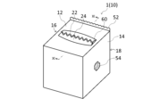
- FIG. 1 is a perspective view showing one embodiment of a sanitary paper storage box according to the present invention.
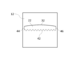
- FIG. FIG. 2 is a plan view showing the sanitary paper storage box of FIG. 1.
- FIG. 2 is a rear view showing the sanitary paper storage box of FIG. 1 .
- FIG. 2 is a side view showing the sanitary paper storage box of FIG. 1 .
- FIG. 2 is a side view showing the sanitary paper storage box of FIG. 1 .
- FIG. FIG. 1 is a diagram for explaining an example of how to use the sanitary paper storage box 1.
- FIG. 1 is a diagram for explaining an example of how to use the sanitary paper storage box 1.
- FIG. 1 is a diagram for explaining an example of how to use the sanitary paper storage box 1.
- FIG. 1 is a diagram for explaining an example of how to use the sanitary paper storage box 1.
- FIG. 1 is a diagram for explaining an example of how to use the sanitary paper storage box
- FIGS. 4A to 4C are diagrams illustrating an example of a manufacturing method for the sanitary paper storage box 1.
- 4A to 4C are diagrams illustrating an example of a manufacturing method for the sanitary paper storage box 1.
- 13 is a side view for explaining a modified example of the cutting blade 52.
- FIG. FIG. 13 is a plan view illustrating a modified example of the cut line 42.
- 13 is a plan view for explaining another modified example of the cut line 42.
- FIG. 13 is a plan view for explaining another modified example of the cut line 42.
- FIG. 13 is a plan view for explaining modified examples of fold lines 32 and 34.
- FIG. 13 is a plan view for explaining a modified example of the main surface 12.
- FIG. 13 is a plan view for explaining a modified example of the main body 10.
- FIG. FIG. 22 is a diagram for explaining the structure of the end face taken along line XXII-XXII in FIG. 21 .
- FIG. 1 is a perspective view showing one embodiment of a sanitary paper storage box according to the present invention.
- FIGS. 2 and 3 are plan and rear views, respectively, of the sanitary paper storage box of FIG. 1.
- FIGS. 4 and 5 are side views of the sanitary paper storage box of FIG. 1.
- the sanitary paper storage box 1 is a box for storing rolled sanitary paper 90, and has a main body 10. Examples of sanitary paper 90 include tissue paper, toilet paper, paper towels, and kitchen paper.
- rolled sanitary paper 90 refers to strip-shaped sanitary paper 90 wound around an axis parallel to the short side direction.
- the sanitary paper 90 may or may not have a cylindrical core in the center.
- the main body 10 is box-shaped. Specifically, the main body 10 is approximately rectangular parallelepiped-shaped.
- the main body 10 has a main surface 12, a side surface 14, and a side surface 16.
- the main surface 12 is the surface where the outlet for the sanitary paper 90 is formed. In this embodiment, the main surface 12 is equal to the top surface of the main body 10.
- the sanitary paper storage box 1 may be used with the main surface 12 facing upwards, or may be used with the main surface 12 facing sideways.
- the side surface 14 and the side surface 16 are a pair of side surfaces perpendicular to the central axis of the sanitary paper 90.
- the central axis of the sanitary paper 90 refers to an imaginary axis that corresponds to the central axis of a cylinder or cylinder when the rolled sanitary paper 90 is viewed as a cylinder or cylinder.
- the main body 10 is preferably configured so that it can be refilled with sanitary paper 90. This can be achieved, for example, by making the main surface 12 openable and closable.
- the main body 10 is flexible.
- the main body 10 can be made of, for example, cardboard or other paper.
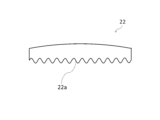
- the main surface 12 has a folding piece 22 (first folding piece), a folding piece 24 (second folding piece), a crease 32 (first crease), a crease 34 (second crease), a cut line 42 (boundary cut line), a cut line 44, and a cut line 46.
- the folding piece 22 is folded diagonally upward from the main surface 12 to create an opening that constitutes an outlet in the main surface 12.
- the folding piece 24 is folded diagonally upward from the main surface 12 to create the above-mentioned opening in the main surface 12 together with the folding piece 22.
- the folding pieces 22 and 24 are folded so that their inner surfaces face each other. In other words, the folding pieces 22 and 24 have a double-door structure.
- the folding pieces 22 and 24 When the direction parallel to the central axis of the sanitary paper 90 is taken as the horizontal direction of the main surface 12 (the left-right direction in Figure 2), the folding pieces 22 and 24 have a horizontally long shape. Note that Figures 1 and 2 show the folding pieces 22 and 24 in their unfolded state.
- the fold line 32 is a fold line for folding the folding piece 22.
- the folding piece 22 is folded along the fold line 32.
- the fold line 32 coincides with the rear end edge of the folding piece 22 (the portion of the periphery of the folding piece 22 that is not separated from the main surface 12 even after the folding piece 22 is folded).
- the fold line 32 is curved and bulges outward from the folding piece 22.
- the apex 32a of the fold line 32 exists on the center line L1 that bisects the main surface 12 in the horizontal direction.
- the apex 32a is the point closest to the side 12a of the main surface 12 (the side on the fold line 32 side of the two sides parallel to the horizontal direction).
- the fold line 32 is symmetrical with respect to the center line L1. It is preferable that the fold line 32 describes a circular arc or an elliptical arc.
- FIG. 6 is a plan view showing the fold line 32.
- the curve ratio of the fold line 32 is preferably 1.9% to 9.7%, and more preferably 1.9% to 4.8%.
- the curve ratio is a numerical value reflecting the magnitude of the curve, and is defined as the value obtained by dividing the length d1 by the length d2.
- the length d1 is equal to the length of the short side of the smallest rectangle R1 that can contain the entire fold line 32.
- the length d1 is, for example, 2 mm to 20 mm.
- the length d2 is equal to the length of the long side of the rectangle R1.
- the long side of the rectangle R1 is parallel to the side 12a of the main surface 12.
- the length d2 is, for example, 80 mm to 200 mm.
- the fold line 34 is a fold line for folding the folding piece 24. That is, the folding piece 24 is folded along the fold line 34.
- the fold line 34 coincides with the rear end edge of the folding piece 24 (the portion of the periphery of the folding piece 24 that is not separated from the main surface 12 even after the folding piece 24 is folded).
- the fold line 34 is curved and bulges outward from the folding piece 24.
- the apex 34a of the fold line 34 is located on the center line L1.
- the apex 34a is the point closest to the side 12b of the main surface 12 (the side on the fold line 34 side of the two sides parallel to the horizontal direction).
- the fold line 34 is symmetrical with respect to the center line L1.
- the fold line 34 is a circular arc or an elliptical arc.
- the fold line 34 has a shape congruent with the fold line 32.
- the fold line 34 is arranged symmetrically with the fold line 32 with respect to the center line L2 that bisects the main surface 12 in its vertical direction (the vertical direction in FIG. 2).
- the curve rate of the fold line 34 is preferably 1.9% to 9.7%, and more preferably 1.9% to 4.8%.
- the definition of the curve rate of the fold line 34 is the same as the definition of the curve rate of the fold line 32.
- the cut line 42 is located at the boundary between the folded pieces 22 and 24.
- the cut line 42 is a perforation.
- the cut line 42 is wavy and extends in the horizontal direction of the main surface 12.
- the cut line 42 is formed along a single continuous wavy line.
- the cut line 42 has a shape without corners.
- the cut line 42 is made up of curves only. In this embodiment, the cut line 42 describes a sine curve.
- FIG. 7 is a plan view showing a portion of the cut line 42.
- the half wavelength d3 of the cut line 42 is preferably 3 mm or more and 10 mm or less, and more preferably 3 mm or more and 5 mm or less.
- the half wavelength d3 is half the wavelength of the cut line 42.
- the total amplitude d4 of the cut line 42 is preferably 3 mm or more and 10 mm or less, and more preferably 3 mm or more and 5 mm or less.
- the total amplitude d4 is twice the amplitude (single amplitude) of the cut line 42.
- FIG. 8 is a plan view showing the bent piece 22.
- the shape of the tip edge 22a of the bent piece 22 (the portion of the periphery of the bent piece 22 facing the bent piece 24) naturally matches the shape of the cut line 42. Therefore, the tip edge 22a is wavy. Furthermore, the tip edge 22a has a shape without corners. Furthermore, the tip edge 22a describes a sine curve.
- the half wavelength of the tip edge 22a (equal to the half wavelength d3 of the cut line 42) is preferably 3 mm or more and 10 mm or less, and more preferably 3 mm or more and 5 mm or less.
- the total amplitude of the tip edge 22a (equal to the total amplitude d4 of the cut line 42) is preferably 3 mm or more and 10 mm or less, and more preferably 3 mm or more and 5 mm or less.
- FIG. 9 is a plan view showing the bent piece 24.
- the shape of the tip edge 24a of the bent piece 24 (the portion of the periphery of the bent piece 24 facing the bent piece 22) naturally matches the shape of the cut line 42. Therefore, the tip edge 24a is wavy. Furthermore, the tip edge 24a has a shape without corners. Furthermore, the tip edge 24a describes a sine curve.
- the half wavelength of the tip edge 24a (equal to the half wavelength d3 of the cut line 42) is preferably 3 mm to 10 mm, more preferably 3 mm to 5 mm.
- the total amplitude of the tip edge 24a (equal to the total amplitude d4 of the cut line 42) is preferably 3 mm to 10 mm, more preferably 3 mm to 5 mm.
- the cut line 44 connects one end of the fold 32 and one end of the fold 34.
- the cut line 44 coincides with the side edge of the folded piece 22 (the part of the periphery of the folded piece 22 other than the rear edge or the leading edge 22a) and the side edge of the folded piece 24 (the part of the periphery of the folded piece 24 other than the rear edge or the leading edge 24a).
- the cut line 44 is a perforation.
- the cut line 44 is a straight line parallel to the vertical direction of the main surface 12.
- the length of the cut line 44 is, for example, 20 mm or more and 40 mm or less.
- the cut line 44 intersects with the cut line 42 at its midpoint. In other words, one end of the cut line 42 coincides with the midpoint of the cut line 44.
- the cut line 46 connects the other end of the fold 32 and the other end of the fold 34.
- the cut line 46 coincides with the side edges of the folded pieces 22 and 24.
- the cut line 46 is a perforation.
- the cut line 46 is a straight line parallel to the vertical direction of the main surface 12.
- the length of the cut line 46 is, for example, 20 mm or more and 40 mm or less.
- the cut line 46 intersects with the cut line 42 at its midpoint. In other words, the other end of the cut line 42 coincides with the midpoint of the cut line 46.
- the cut line 46 is arranged symmetrically with the cut line 44 with the center line L1 as the axis of symmetry.
- the main body 10 further has a cutting blade 52, and an insertion portion 54 and an insertion portion 56.
- the cutting blade 52 is a portion for cutting the sanitary paper 90 pulled out from the outlet.
- the cutting blade 52 is provided at a position separated from the folded pieces 22 and 24.
- the cutting blade 52 is provided on the periphery of the main surface 12. In a plan view, the cutting blade 52 overlaps with the edge 12a of the main surface 12 (see FIG. 2).
- the cutting blade 52 is formed integrally with the side surface 18 of the main body 10 (see FIG. 3).
- the side surface 18 is a side surface that is perpendicular to the side surfaces 14 and 16.
- the cutting blade 52 protrudes above the main surface 12 (see FIGS. 4 and 5).
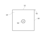
- the insertion portion 54 is a portion that is inserted into the gap in the center of the sanitary paper 90.
- the insertion portion 54 is provided on the side surface 14 of the main body 10 as shown in FIG. 4.
- the insertion portion 54 has a cut line 54a.
- the cut line 54a consists of multiple line segments connecting the center of the insertion portion 54 and each vertex.
- the cut line 54a is a perforation.
- the tongue piece (the triangular part with each side as the base) can be folded inwardly along the periphery (each side of the polygon) of the insertion portion 54 to insert the insertion portion 54 (multiple tongue pieces) into the center of the sanitary paper 90.
- the insertion portion 54 is made up of a part of the side surface 14.
- the insertion portion 56 is a portion that is inserted into the gap in the center of the sanitary paper 90.
- the insertion portion 56 is provided on the side surface 16 of the main body 10 as shown in FIG. 5.
- the outer shape of the insertion portion 56 is a polygon. It is preferable that the outer shape of the insertion portion 56 is a regular n-sided polygon, similar to the outer shape of the insertion portion 54.
- the insertion portion 56 has a cut line 56a.
- the cut line 56a is made up of multiple line segments connecting the center of the insertion portion 56 and each vertex.
- the cut line 56a is a perforation.
- the tongue piece (the triangular part with each side as the base) is folded inward along the periphery (each side of the polygon) of the insertion portion 56, so that the insertion portion 56 (multiple tongue pieces) can be inserted into the center of the sanitary paper 90.
- the insertion portion 56 is made up of a part of the side surface 16.
- the insertion portions 54 and 56 are positioned so that they completely overlap each other when viewed from a direction perpendicular to the side surfaces 14 and 16.
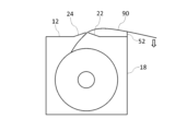
- Figure 10 is a perspective view showing the sanitary paper storage box 1 when in use.
- Figure 11 is a view for explaining the structure of the end face along the line XI-XI in Figure 10.
- the sanitary paper 90 is not shown.
- one end of the sanitary paper 90 is pulled out from the main body 10. Then, as shown in FIG. 12, the pulled out sanitary paper 90 is cut by pressing it against the tip of the cutting blade 52. This allows a cut piece of sanitary paper 90 of the desired length to be obtained. Note that, unlike typical tissue paper storage boxes, the sanitary paper storage box 1 does not have a plastic film at the outlet.
- a sheet 70 of sufficient size is prepared, and the sheet 70 is cut into the shape shown in Figure 13.
- the sheet 70 is made of a single piece of cardboard.
- the cut sheet 70 includes a portion 12p that will become the main surface 12, a portion 13p that will become the bottom surface of the main body 10 (the surface opposite to the main surface 12), a portion 14p that will become the side surface 14, a portion 16p that will become the side surface 16, a portion 18p that will become the side surface 18, and a portion 19p that will become the remaining side surfaces of the main body 10 (the sides other than the sides 14, 16, and 18).
- the portion 12p has folded pieces 22 and 24, fold lines 32 and 34, and cut lines 42, 44, and 46 formed therein.
- An insertion portion 72 is connected to three sides of the portion 12p.
- An insertion portion 54 is formed in the portion 14p.
- a gluing portion 74 is connected to two sides of the portion 14p.
- An insertion portion 56 is formed in portion 16p.
- a margin portion 76 is connected to two sides of portion 16p.
- a cutting blade 52 is connected to portion 18p. Note that FIG. 13 shows the inner surfaces of each of portions 12p, 13p, 14p, 16p, 18p, and 19p (the inner surfaces of main body 10).
- Fold F1 is located at the boundary between portion 12p and portion 16p.
- Fold F2 is located at the boundary between portion 12p and each of the insertion portions 72.
- Fold F3 is located at the boundary between portion 13p and portion 14p.
- Fold F4 is located at the boundary between portion 14p and each of the glue tabs 74.
- Fold F5 is located at the boundary between portion 13p and portion 16p.
- Fold F6 is located at the boundary between portion 16p and each of the glue tabs 76.
- Fold F7 is located at the boundary between portion 13p and portion 18p.
- Fold F8 is located at the boundary between portion 13p and portion 19p.
- the adhesive portion 74 is glued to the inner surface of the portion 18p and the portion 19p
- the adhesive portion 76 is glued to the inner surface of the portion 18p and the portion 19p.
- the insertion portion 72 is inserted into the space surrounded by the portion 13p, the portion 14p, the portion 16p, the portion 18p, and the portion 19p so that the insertion portion 72 overlaps with the inner surfaces of the portion 14p, the portion 18p, and the portion 19p.
- the sanitary paper storage box 1 main body 10 shown in FIG. 1 to FIG. 5 is obtained.
- the main body 10 is obtained from one sheet 70.
- the insertion portion 72 may or may not be glued to the inner surface of each portion 14p, 18p, and 19p. In the former case, it is necessary to place the sanitary paper 90 in the above space prior to gluing. In the latter case, the main body 10 having the main surface 12 that can be opened and closed is obtained.
- the sanitary paper storage box 1 has a folding piece 22 that can be folded diagonally upward from the main surface 12. By folding the folding piece 22, an opening 60 that forms the removal port can be created in the main surface 12. At this time, the folding piece 22 is folded along the fold line 32, which has a curved shape that bulges outward from the folding piece 22. In this case, unlike when the folding piece 22 is folded along the fold line 32, a force (return force) that tries to return the folding piece 22 to its original state (unfolded state) acts on the folding piece 22 that is folded along the fold line 32. For this reason, it is possible to prevent the folding angle of the folding piece 22 from becoming too large. Therefore, a sanitary paper storage box 1 that can suppress the intrusion of dust into the main body 10 through the removal port is realized.
- the fold 34 also has a curved shape that bulges outward from the folding piece 24.
- a restoring force also acts on the folding piece 24 that is folded along the fold 34. This makes it possible to prevent the folding angle of the folding piece 24 from becoming too large. This further prevents dust from entering the main body 10 through the removal opening.
- the mechanism by which the curved fold line 32 regulates the bending angle of the folding piece 22 will now be elaborated upon. If the main body 10 is rigid (not flexible), the folding piece 22 cannot be bent along a curve. In contrast, in the sanitary paper storage box 1, the main body 10 is flexible, so even if the fold line 32 is curved, the bending of the main body 10 makes it possible to bend the folding piece 22 to a certain degree of angle. At this time, a return force acts on the folding piece 22 due to the restoring force of the main body 10. This regulates the bending angle of the folding piece 22. The same applies to the mechanism by which the curved fold line 34 regulates the bending angle of the folding piece 24.
- the fold line 32 forms a circular or elliptical arc
- it contributes to improving the aesthetic appearance of the fold line 32 and therefore the sanitary paper storage box 1.
- the fold line 34 forms a circular or elliptical arc, it contributes to improving the aesthetic appearance of the fold line 34 and therefore the sanitary paper storage box 1.
- Increasing the curve rate of the fold line 32 is advantageous in strengthening the return force acting on the folding piece 22. From this perspective, it is preferable that the curve rate of the fold line 32 is 1.9% or more. On the other hand, if the curve rate of the fold line 32 is too large, the return force will be excessively strong, which may make it difficult to remove the sanitary paper 90 from the main body 10. From this perspective, it is preferable that the curve rate of the fold line 32 is 9.7% or less, and more preferably 4.8% or less.
- Increasing the curve rate of the fold line 34 is advantageous in strengthening the return force acting on the folding piece 24. From this perspective, it is preferable that the curve rate of the fold line 34 is 1.9% or more. On the other hand, if the curve rate of the fold line 34 is too large, the return force will be excessively strong, which may make it difficult to remove the sanitary paper 90 from the main body 10. From this perspective, it is preferable that the curve rate of the fold line 34 is 9.7% or less, and more preferably 4.8% or less.
- the tip edge 22a of the folded piece 22 is wavy. In this case, the tip edge 22a has unevenness. This allows the holding force of the folded piece 22 against the sanitary paper 90 to be strengthened.
- the tip edge 24a of the folded piece 24 is wavy. In this case, the tip edge 24a has unevenness. This allows the holding force of the folded piece 24 against the sanitary paper 90 to be strengthened.
- the leading edge 22a of the folded piece 22 has a shape without corners. This makes it difficult for the sanitary paper 90 to get caught on the leading edge 22a when removing the paper, making it easier to remove the sanitary paper 90 smoothly.
- the leading edge 24a of the folded piece 24 has a shape without corners. This makes it difficult for the sanitary paper 90 to get caught on the leading edge 24a when removing the paper, making it easier to remove the sanitary paper 90 smoothly.
- the tip edge 22a of the folded piece 22 describes a sine curve. This contributes to improving the aesthetics of the folded piece 22 and therefore the sanitary paper storage box 1.
- the tip edge 24a of the folded piece 24 describes a sine curve. This contributes to improving the aesthetics of the folded piece 24 and therefore the sanitary paper storage box 1.
- the half wavelength of the leading edge 22a of the folded piece 22 is advantageous in strengthening the holding power of the folded piece 22 to the sanitary paper 90, since the unevenness of the leading edge 22a becomes finer. From this perspective, the half wavelength of the leading edge 22a is preferably 10 mm or less, and more preferably 5 mm or less. On the other hand, if the half wavelength of the leading edge 22a is too small, the sanitary paper 90 will easily get caught on the leading edge 22a. From this perspective, the half wavelength of the leading edge 22a is preferably 3 mm or more.
- the half wavelength of the leading edge 24a of the folded piece 24 is advantageous in strengthening the holding power of the folded piece 24 against the sanitary paper 90, since the unevenness of the leading edge 24a becomes finer. From this perspective, the half wavelength of the leading edge 24a is preferably 10 mm or less, and more preferably 5 mm or less. On the other hand, if the half wavelength of the leading edge 24a is too small, the sanitary paper 90 will easily get caught on the leading edge 24a. From this perspective, the half wavelength of the leading edge 24a is preferably 3 mm or more.
- the total amplitude of the tip edge 22a of the folded piece 22 increases the unevenness of the tip edge 22a, which is advantageous in strengthening the holding power of the folded piece 22 against the sanitary paper 90. From this perspective, it is preferable that the total amplitude of the tip edge 22a is 3 mm or more. On the other hand, if the total amplitude of the tip edge 22a is too large, the sanitary paper 90 will penetrate too deeply into the recess, preventing smooth removal of the sanitary paper 90. From this perspective, it is preferable that the total amplitude of the tip edge 22a is 10 mm or less, and more preferably 5 mm or less.
- the total amplitude of the tip edge 24a of the folded piece 24 increases the unevenness of the tip edge 24a, which is advantageous in strengthening the holding power of the folded piece 24 against the sanitary paper 90. From this perspective, it is preferable that the total amplitude of the tip edge 24a is 3 mm or more. On the other hand, if the total amplitude of the tip edge 24a is too large, the sanitary paper 90 will penetrate too deeply into the recess, preventing smooth removal of the sanitary paper 90. From this perspective, it is preferable that the total amplitude of the tip edge 24a is 10 mm or less, and more preferably 5 mm or less.
- the main body 10 has a cutting blade 52. This makes it easier to cut the sanitary paper 90 neatly compared to cutting the sanitary paper 90 pulled out of the main body 10 by hand.
- the cutting blade 52 is located at a position separated from the folded piece 22 (and folded piece 24). In this case, after cutting, the sanitary paper 90 pulled out of the main body 10 remains between the folded piece 22 and the cutting blade 52. This has the advantage that the sanitary paper 90 can be easily picked up the next time it is pulled out.
- the cutting blade 52 is provided on the periphery of the main surface 12. In this case, by connecting the cutting blade 52 to the side of the main body 10, the main body 10 having the cutting blade 52 can be realized with a simple configuration. In fact, in the sanitary paper storage box 1, the cutting blade 52 is connected to the upper end of the side surface 18.
- the main body 10 has insertion sections 54, 56. This makes it difficult for the central axis of the sanitary paper 90 to wobble. This is advantageous for stably pulling out the sanitary paper 90 from the main body 10.
- the insertion portion 54 is made of a part of the side surface 14 of the main body 10. This allows the main body 10 having the insertion portion 54 to be realized with a simple configuration.
- the insertion portion 56 is made of a part of the side surface 16 of the main body 10. This allows the main body 10 having the insertion portion 56 to be realized with a simple configuration.
- each insertion portion 54, 56 is a regular n-sided polygon (n is an integer of 5 or more), the outer shape is close to a circle. This makes it easier to smoothly rotate the sanitary paper 90 with the insertion portion 54, 56 inserted in the center.
- the outer surface of the main body 10 can be used as a canvas for drawing. Also, if a line drawing is printed on the outer surface of the main body 10 in advance, the user can enjoy coloring in it. In other words, a line drawing for coloring may be printed on the outer surface of the main body 10. For this reason, the sanitary paper storage box 1 is also suitable as a toy for children.
- the entire body 10, including the cutting blade 52, the insertion portion 54, and the insertion portion 56, are made of the same material. This helps reduce the manufacturing costs of the sanitary paper storage box 1.
- the main body 10 is configured to be refilled with sanitary paper 90, the main body 10 can be reused by refilling it with new sanitary paper 90 even after the sanitary paper 90 has been used up, which is economical. This also leads to a reduction in waste (unnecessary main bodies 10), thereby contributing to a reduction in the burden on the environment.
- the sanitary paper storage box 1 does not have a plastic film at the outlet. This also leads to a reduction in waste (unnecessary plastic), which contributes to reducing the burden on the environment.
- the present invention is not limited to the above embodiment, and various modifications are possible.
- the entire main body 10 is made of a single material.
- the main body 10 may be made of multiple materials.
- plastic or metal as the material for the cutting blade 52
- cardboard as the material for the remainder of the main body 10 (portions other than the cutting blade 52).
- cardboard as the material for the main surface 12, while using another material as the material for the remainder of the main body 10 (portions other than the main surface 12).
- other materials include cardboard, CNF (cellulose nanofiber), wood, plastic, or metal.
- each insertion portion 54, 56 is an n-sided polygon (n is an integer of 5 or more).
- the outer shape of each insertion portion 54, 56 may be a triangle or a rectangle. In that case, while it becomes more difficult for the sanitary paper 90 to rotate smoothly, it becomes more difficult for the sanitary paper 90 to rotate in the reverse direction. This has the advantage that the sanitary paper 90 pulled out of the main body 10 is less likely to go back in.
- the main body 10 may be provided with only either the insertion portion 54 or the insertion portion 56. Alternatively, the main body 10 may not be provided with either the insertion portion 54 or the insertion portion 56.
- the cutting blade 52 protrudes above the main surface 12.
- the cutting blade 52 may protrude to the side of the main surface 12, as shown in FIG. 15, for example.
- the cutting blade 52 can be formed integrally with the main surface 12.
- the case where the cutting blade 52 is provided on the main body 10 is exemplified.
- the main body 10 does not have to be provided with a cutting blade 52.
- the sanitary paper 90 pulled out from the main body 10 may be cut by hand or by the leading edge 22a of the folded piece 22 or the leading edge 24a of the folded piece 24.
- the cut line 42 is wavy.
- the cut line 42 may be curved and bulged toward the folded piece 22 or the folded piece 24, as shown in FIG. 16.
- the cut line 42 is curved and bulged toward the folded piece 22.
- the curve rate of the cut line 42 is equal to the curve rate of each fold 32, 34.
- the leading edge 22a of the folding piece 22 is concave and the leading edge 24a of the folding piece 24 is convex.
- the leading edge 22a is concave in this way, the sanitary paper 90 is more likely to wrinkle when it passes near the leading edge 22a.
- the sanitary paper 90 spreads in the vertical direction of the main surface 12, making it easier for the sanitary paper 90 to remain sandwiched between the folding pieces 22 and 24. This makes it less likely for the sanitary paper 90 pulled out of the outlet to fall into the main body 10.
- the leading edge 24a of the folding piece 24 is convex, the leading edge 24a is more likely to come into contact with the sanitary paper 90.
- the curve rate of the cut line 42 may be greater or smaller than the curve rate of each crease 32, 34.
- the cut line 42 may be a straight line, as shown in FIG. 17, for example. In that case, it becomes easier to make cuts along the cut line 42.
- the cut line 42 is made up of a single line.
- the cut line 42 may be made up of multiple lines, as shown in FIG. 18, for example.
- the cut line 42 is made up of cut line 42a and cut line 42b.
- the cut line 42a has multiple convex portions that protrude toward the cut line 42b side.
- Each of the convex portions that make up the cut line 42a is a round convex portion with a rounded tip.
- the cut line 42b has multiple convex portions that protrude toward the cut line 42a side.
- Each of the convex portions that make up the cut line 42b is also a round convex portion.
- cut lines 42 cut lines 42a, 42b), 44, and 46
- the portion between cut lines 42a and 42b is cut out from main surface 12. Therefore, even when folding pieces 22 and 24 are not folded, a gap is created between them. This is advantageous for making it easier to remove sanitary paper 90 smoothly.
- the curve rate of the fold line 34 is equal to the curve rate of the fold line 32.
- the curve rate of the fold line 34 may be greater or smaller than the curve rate of the fold line 32.
- both the fold line 32 and the fold line 34 are curved.
- only one of the fold line 32 or the fold line 34 may be curved.
- the fold line 32 is curved and bulges outward from the folded piece 22, while the fold line 34 is straight.
- folding pieces 22 and 24 are provided on main surface 12.
- only one of folding pieces 22 or 24 may be provided on main surface 12, as shown in FIG. 20, for example.
- only folding piece 22 is provided on main surface 12.
- folding line 32 and folding line 34 only folding line 32 is provided on main surface 12.
- cut line 44 extends from one end of folding line 32 to one end of cutting line 42.
- cut line 46 extends from the other end of folding line 32 to the other end of cutting line 42.
- folding piece 24 and fold line 34 correspond to the "first folding piece" and "first fold line", respectively.
- the main body 10 may store multiple sanitary paper 90, for example, as shown in Figures 21 and 22.
- Figure 22 is a diagram for explaining the structure of the end face along the line XXII-XXII in Figure 21.
- two sanitary paper 90 are stored in the main body 10.
- a partition 10a is provided in the main body 10 to separate the two sanitary paper 90.
- the main surface 12 has multiple folding pieces 22 and multiple fold lines 32 to correspond to the multiple sanitary paper 90.
- one folding piece 22 creates an opening in the main surface 12 that forms an outlet for one sanitary paper 90
- the other folding piece 22 creates an opening in the main surface 12 that forms an outlet for the other sanitary paper 90
- the main surface 12 has multiple folding pieces 24 and multiple fold lines 34 to correspond to the multiple sanitary paper 90.
- sanitary papers 90 are stored in the main body 10 in this way, convenience for the user is improved. For example, if multiple different types of sanitary papers 90 are stored in the main body 10, the user can selectively remove the appropriate sanitary paper 90 from the main body 10 depending on the application. Also, by providing multiple folding pieces 22 and multiple folds 32 to correspond to multiple sanitary papers 90, the multiple sanitary papers 90 can be removed from separate removal openings. This prevents multiple sanitary papers 90 from interfering with each other, allowing each sanitary paper 90 to be removed smoothly.
- the cut lines 42, 44, and 46 are perforations.
- the cut lines 42, 44, and 46 are configured so that cuts are made along the cut lines 42, 44, and 46 only when force is applied to both sides of the cut lines 42, 44, and 46.
- the cut lines 42, 44, and 46 may be pre-cut. The same applies to the cut lines 54a and 56a.
Landscapes
- Engineering & Computer Science (AREA)
- Mechanical Engineering (AREA)
- Housing For Livestock And Birds (AREA)
- Sanitary Thin Papers (AREA)
Priority Applications (2)
| Application Number | Priority Date | Filing Date | Title |
|---|---|---|---|
| PCT/JP2024/018262 WO2024150835A2 (ja) | 2024-05-17 | 2024-05-17 | 衛生用紙収納箱 |
| JP2024529872A JPWO2024150835A1 (en)van) | 2024-05-17 | 2024-05-17 |
Applications Claiming Priority (1)
| Application Number | Priority Date | Filing Date | Title |
|---|---|---|---|
| PCT/JP2024/018262 WO2024150835A2 (ja) | 2024-05-17 | 2024-05-17 | 衛生用紙収納箱 |
Publications (2)
| Publication Number | Publication Date |
|---|---|
| WO2024150835A2 true WO2024150835A2 (ja) | 2024-07-18 |
| WO2024150835A3 WO2024150835A3 (ja) | 2024-09-19 |
Family
ID=91896415
Family Applications (1)
| Application Number | Title | Priority Date | Filing Date |
|---|---|---|---|
| PCT/JP2024/018262 WO2024150835A2 (ja) | 2024-05-17 | 2024-05-17 | 衛生用紙収納箱 |
Country Status (2)
| Country | Link |
|---|---|
| JP (1) | JPWO2024150835A1 (en)van) |
| WO (1) | WO2024150835A2 (en)van) |
Family Cites Families (10)
| Publication number | Priority date | Publication date | Assignee | Title |
|---|---|---|---|---|
| JPH0420745Y2 (en)van) * | 1987-12-25 | 1992-05-12 | ||
| JPH0468882U (en)van) * | 1990-10-23 | 1992-06-18 | ||
| JPH079195U (ja) * | 1993-07-26 | 1995-02-10 | 寛之 渡辺 | トイレット・ペーパー使用ティッシュ・ペーパー箱 |
| JP2003260006A (ja) * | 2002-03-07 | 2003-09-16 | Tm Giken Kk | ペーパーボックス |
| JP2004059150A (ja) * | 2002-09-05 | 2004-02-26 | Jiro Ishida | ティシューボックス等の取り出し口構造 |
| JP3132893U (ja) * | 2007-04-12 | 2007-06-21 | アイパックスイケタニ株式会社 | ロールペーパー繰り出し容器 |
| JP2009184719A (ja) * | 2008-02-08 | 2009-08-20 | Daiki:Kk | 取出口片を蓋として使用するティッシュペーパーボックス |
| JP5564218B2 (ja) * | 2009-08-31 | 2014-07-30 | 大王製紙株式会社 | トイレットロール製品 |
| JP6615274B2 (ja) * | 2018-06-18 | 2019-12-04 | 株式会社無有 | 衛生用紙収納箱 |
| JP6649446B2 (ja) * | 2018-09-14 | 2020-02-19 | 株式会社無有 | 衛生用紙収納箱 |
-
2024
- 2024-05-17 JP JP2024529872A patent/JPWO2024150835A1/ja active Pending
- 2024-05-17 WO PCT/JP2024/018262 patent/WO2024150835A2/ja unknown
Also Published As
| Publication number | Publication date |
|---|---|
| WO2024150835A3 (ja) | 2024-09-19 |
| JPWO2024150835A1 (en)van) | 2024-07-18 |
Similar Documents
| Publication | Publication Date | Title |
|---|---|---|
| AU2002238550B2 (en) | Box with hinged lid | |
| RU2494945C2 (ru) | Выдачное устройство для выдачи бумаги тиссью и способ изготовления выдачного устройства | |
| US7134572B2 (en) | Container for a stack of interfolded tissue sheets | |
| JP6649446B2 (ja) | 衛生用紙収納箱 | |
| AU2008221543A1 (en) | Cigarette packet and cut sheet | |
| JP5475552B2 (ja) | 家庭用薄葉紙収納箱 | |
| JP2010254378A (ja) | 衛生用紙入りカートン | |
| CN100519361C (zh) | 放置卫生纸的纸盒 | |
| JP5616998B2 (ja) | 家庭用薄葉紙収納箱及び家庭用薄葉紙収納箱における家庭用薄葉紙の詰め替え方法 | |
| TWI453152B (zh) | 捲繞體收納箱及裝有捲繞體之收納箱 | |
| JP4681251B2 (ja) | 衛生用紙入りカートン | |
| JP6615270B2 (ja) | 衛生用紙収納箱 | |
| WO2024150835A2 (ja) | 衛生用紙収納箱 | |
| WO2024150836A2 (ja) | 衛生用紙収納箱 | |
| JP7714203B2 (ja) | 物品収納箱 | |
| WO2025037652A2 (ja) | 物品収納箱 | |
| JP2008195421A (ja) | カートン収納用衛生用紙及びその製造方法、並びにカートン入り衛生用紙 | |
| JP2004018010A (ja) | 衛生薄葉紙収納箱 | |
| WO2024172169A1 (ja) | 物品収納箱 | |
| JP7291549B2 (ja) | 巻回体収納箱 | |
| JP4362542B1 (ja) | 折りたたみ眼鏡ケース | |
| JP2007297079A (ja) | 衛生用紙収納用カートン | |
| JP4790581B2 (ja) | 包装用箱 | |
| JPH09295637A (ja) | ロールシートカット機能付き箱 | |
| WO2024167028A2 (ja) | 物品収納箱 |
Legal Events
| Date | Code | Title | Description |
|---|---|---|---|
| ENP | Entry into the national phase |
Ref document number: 2024529872 Country of ref document: JP Kind code of ref document: A |
|
| 121 | Ep: the epo has been informed by wipo that ep was designated in this application |
Ref document number: 24741607 Country of ref document: EP Kind code of ref document: A2 |