WO2024150555A1 - 液体クロマトグラフ装置 - Google Patents
液体クロマトグラフ装置 Download PDFInfo
- Publication number
- WO2024150555A1 WO2024150555A1 PCT/JP2023/043117 JP2023043117W WO2024150555A1 WO 2024150555 A1 WO2024150555 A1 WO 2024150555A1 JP 2023043117 W JP2023043117 W JP 2023043117W WO 2024150555 A1 WO2024150555 A1 WO 2024150555A1
- Authority
- WO
- WIPO (PCT)
- Prior art keywords
- column
- side heat
- temperature sensor
- heat block
- temperature
- Prior art date
- Legal status (The legal status is an assumption and is not a legal conclusion. Google has not performed a legal analysis and makes no representation as to the accuracy of the status listed.)
- Ceased
Links
Images


Classifications
-
- G—PHYSICS
- G01—MEASURING; TESTING
- G01N—INVESTIGATING OR ANALYSING MATERIALS BY DETERMINING THEIR CHEMICAL OR PHYSICAL PROPERTIES
- G01N30/00—Investigating or analysing materials by separation into components using adsorption, absorption or similar phenomena or using ion-exchange, e.g. chromatography or field flow fractionation
- G01N30/02—Column chromatography
- G01N30/50—Conditioning of the sorbent material or stationary liquid
- G01N30/52—Physical parameters
- G01N30/54—Temperature
-
- G—PHYSICS
- G01—MEASURING; TESTING
- G01N—INVESTIGATING OR ANALYSING MATERIALS BY DETERMINING THEIR CHEMICAL OR PHYSICAL PROPERTIES
- G01N30/00—Investigating or analysing materials by separation into components using adsorption, absorption or similar phenomena or using ion-exchange, e.g. chromatography or field flow fractionation
- G01N30/02—Column chromatography
- G01N30/60—Construction of the column
- G01N30/6091—Cartridges
Definitions
- the present invention relates to a liquid chromatography device.
- Liquid chromatographs are known as analytical devices that analyze substances contained in samples.
- the liquid mobile phase is pressurized by a pump or other device to pass it through an analytical column, and the substances to be analyzed are separated and detected with high efficiency by utilizing the difference in the interactions between the stationary phase and the mobile phase.
- liquid delivery and temperature conditions are set for each substance being analyzed, and each part is controlled under those set conditions to separate and detect the substance being analyzed.
- liquid chromatograph it is important to control the temperature of the analytical column to match the set temperature conditions, and for this reason liquid chromatograph equipment is equipped with a column oven for temperature regulation.
- the column oven of conventional liquid chromatography equipment regulates the temperature of the analytical column in a constant temperature atmosphere, so it is not possible to accurately measure or estimate the temperature of the analytical column.
- the analytical column is a part that requires replacement, and it is difficult to attach a temperature sensor to the separation column.
- Liquid chromatograph devices in which a sensor and a heater are mounted on the analytical column itself, which is a consumable item, are also known, for example from Patent Document 1 and Patent Document 2.
- a sensor and a heater are provided on the analytical column itself, when the analytical column needs to be replaced due to performance deterioration or clogging, the sensor and heater mounted on the analytical column must also be discarded, which increases the environmental burden.
- the present invention provides a liquid chromatograph that can accurately manage and control the temperature of an analytical column while minimizing the increase in environmental load.
- the liquid chromatograph of the present invention comprises a column cartridge configured to accommodate an analytical column and equipped with a column-side heat block configured to transfer heat to the analytical column, and a main body configured to accommodate the column cartridge and equipped with a column oven-side heat block that contacts the column-side heat block and transfers heat to the column-side heat block.
- the main body comprises a first temperature sensor that measures the temperature of the column oven-side heat block, a second temperature sensor that measures the temperature inside the column cartridge, and a determination unit that determines whether the column oven-side heat block is in contact with the column-side heat block based on the measurement results of the first temperature sensor and the second temperature sensor.
- the present invention makes it possible to provide a liquid chromatograph that can accurately manage and control the temperature of an analytical column while minimizing the increase in environmental load.
- FIG. 1 is a schematic diagram illustrating an overall configuration of a liquid chromatograph apparatus 100 according to a first embodiment.
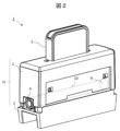
- FIG. 2 is a schematic perspective view illustrating an example of the structure of the column cartridge 1.
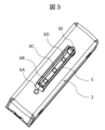
- FIG. 2 is a perspective view showing an example of the structure of the upper surface of the column cartridge 1.
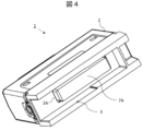
- FIG. 2 is a perspective view showing an example of the structure of the bottom surface of the column cartridge 1.
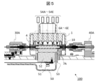
- 3 is a cross-sectional view illustrating the details of the structure of the column cartridge 1 and the details of the structure of a main body portion 50.
- FIG. FIG. 4 is a cross-sectional view illustrating a configuration of a liquid chromatograph apparatus 100 according to a second embodiment.
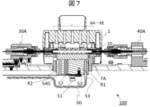
- FIG. 11 is a cross-sectional view illustrating the configuration of a liquid chromatograph apparatus 100 according to a third embodiment.
- the liquid chromatograph 100 includes a column cartridge 1, an analytical column 10, a liquid delivery pump 20, an injector 30, a detection unit 40, and a main body 50.
- the liquid delivery pump 20, the injector 30, the column cartridge 1, and the detection unit 40 are connected by piping.
- the liquid delivery pump 20 is located at the most upstream side of the analysis flow path, and has the function of pumping the mobile phase from a container (not shown) that contains the mobile phase and delivering it to the injector 30.
- the injector 30 has the role of aspirating a sample from a sample container that contains the sample, for example using a probe, and injecting the aspirated sample into the analysis column 10 installed in the column cartridge 1.
- the column cartridge 1 is a storage container configured to be able to mount and store an analytical column 10.
- the column cartridge 1 is configured so that the analytical column 10 can be fixed to the housing of the column cartridge 1 by a metal block MB.
- the metal block MB is provided with a column-side heat block 7A below it. This column-side heat block 7A is configured so that it can be exposed to the outside through a hole provided in the bottom surface of the column cartridge 1.
- the detection unit 40 analyzes the mobile phase discharged from the analytical column 10 to perform an analysis of the target micro-substance.
- the main body 50 is equipped with an arithmetic and control unit 200. In accordance with signals from the detection unit 40, the arithmetic and control unit 200 performs various calculations related to the target substance, and outputs control signals to control the liquid delivery pump 20, the injector 30, and the detection unit 40.
- the main body 50 also includes a column oven that generates heat to be provided to the column-side heat block 7A described above.
- the column oven is a mechanism for generating heat to control the temperature of the analytical column 10 at a constant temperature, and is roughly composed of a heater 51 and a column-oven-side heat block 52, for example.
- the column-oven-side heat block 52 is configured to contact the bottom surface of the column-side heat block 7A described above.
- the heater 51 is connected, for example, to the bottom surface of the column-oven-side heat block 52, and the heater 51 operates to generate heat, which is then transferred to the column-oven-side heat block 52.
- the liquid chromatograph 100 is equipped with a first temperature sensor 53 and a second temperature sensor 54 as temperature sensors for measuring the temperature of the analytical column 10.
- the first temperature sensor 53 is embedded in the aforementioned column oven side heat block 52 and measures the temperature of the column oven side heat block 52.
- the second temperature sensor 54 is arranged and configured to measure the temperature inside the column cartridge 1, for example, the temperature of the metal block MB.
- the second temperature sensor 54 can be configured to be able to measure the temperature through a window provided in the column cartridge 1.
- the column cartridge 1 comprises an upper housing part 2 made of resin and a lower housing part 3 made of resin.
- the upper housing part 2 and the lower housing part 3 form a housing H that houses an analytical column 10 therein. That is, the upper housing part 2 is provided above the analytical column 10, while the lower housing part 3 is provided below the analytical column 10, and the analytical column 10 is housed inside the housing H formed by the upper housing part 2 and the lower housing part 3.
- the analytical column 10 is fixed inside the housing H by a metal block MB.
- a handle portion (protrusion) 5 is formed on the top surface of the upper housing portion 2.
- a first flow path port 4 is formed on the side of the housing between the upper housing portion 2 and the lower housing portion 3 as one end of the analytical column 10, and the analytical column 10 is held within the housing H in such a manner that the first flow path port 4 is exposed from the housing H.
- the mobile phase flows into this first flow path port 4.
- a second flow path port 9 is formed on the opposite side of the housing H as the other end of the analytical column 10, and the analytical column 10 is held within the housing H such that the second flow path port 9 is similarly exposed to the outside of the housing H.
- Temperature detection windows 6A, 6B, 6C, 6D, and 6E are provided on the upper surface of the upper housing part 2. These windows 6A to 6E are connected to the storage space of the analytical column 10.
- the windows 6A, 6B, 6C, 6D, and 6E are arranged along the longitudinal direction of the analytical column 10. In Figure 3, some of the windows 6B, 6C, and 6D are formed at the position where the handle part 5 is formed, and the other windows 6A and 6E are arranged outside the handle part 5 (on the longitudinal extension line), but this is just an example and is not limited to what is shown.
- the diameters of the windows 6A, 6B, 6C, 6D, and 6E are preferably about 1.4 mm or less.
- Figure 4 shows an example of the structure of the bottom surface of the column cartridge 1.
- An opening 3A is formed in the bottom surface of the lower housing part 3.
- a column side heat block 7A of the lower metal block part 7 (described later) is inserted into this opening 3A, and the column side heat block 7A is exposed to the outside from the opening 3A.
- the column side heat block 7A comes into contact with the column oven side heat block 52, and receives heat from the column oven and transfers the heat to the analytical column 10.
- the column cartridge 1 has windows 6A-6E that extend from the top surface to the metal block MB for temperature detection. Infrared rays are irradiated from the infrared temperature sensors 54A-54E, which are an example of the second temperature sensor 54, through the windows 6A-6E, and the reflected light is detected.
- the infrared temperature sensors 54A-54E are located outside the column cartridge 1, not inside it, and form part of the main body 50.
- the analytical column 10 mounted in the column cartridge 1 is connected to the guide block 30A and the guide block 40A at the first flow path port 4 and the second flow path port 9, respectively.
- the guide block 30A and the guide block 40A are mounted on guide rails (not shown) that extend horizontally on the paper and are configured to be movable along the horizontal direction on the paper.
- the analytical column 10 is connected to the injector 30 and the detection unit 40 mentioned above via the guide blocks 30A and 40A.
- the detection signals of the first temperature sensor 53 and the second temperature sensor 54 are input to the calculation control unit 200, which estimates the temperature of the analytical column 10.
- the calculation control unit 200 also determines whether the column-side heat block 7A and the column-oven-side heat block 52 are in proper contact according to the difference between the detection signals of the first temperature sensor 53 and the second temperature sensor 54.
- the calculation control unit 200 functions as a determination unit that determines whether the two heat blocks 7A, 52 are in proper contact according to the difference between the detection signals of the temperature sensors 53, 54A-54E.
- the calculation control unit 200 can determine whether or not proper contact is being made between the two heat blocks based on this temperature difference.
- the column cartridge 1 equipped with the column side heat block 7A is mounted on the main body 50, and the column oven side heat block 52 of the main body 50 is arranged so as to be in contact with this column side heat block 7A.
- the first temperature sensor 53 mounted on the column oven side heat block 52 and the second temperature sensors 54A-E that measure the temperature of the column cartridge 1 measure the temperature of the analytical column 10, and can also determine whether or not there is appropriate contact between the two heat blocks 7A, 52. Since both of the two temperature sensors 53, 54 are provided on the main body 50 side, according to this embodiment, it is possible to provide a liquid chromatograph that can accurately manage and control the temperature of the analytical column while suppressing an increase in the environmental load.
- a liquid chromatograph 100 according to a second embodiment will be described with reference to Fig. 6.
- the liquid chromatograph 100 according to the second embodiment is similar to the first embodiment in its overall configuration and the structure of the column cartridge 1 (Figs. 1 to 4), so a duplicated description will be omitted.
- This second embodiment differs from the first embodiment in that the second temperature sensor 54 is a probe-type temperature sensor 54F equipped with a contact-type probe.
- the probe-type temperature sensor 54F has a contact-type probe that can be inserted into the windows 6A-6E, and can measure the temperature of the analytical column 10 by contacting this contact-type probe with, for example, a metal block MB. Note that it is also possible to provide multiple probe-type temperature sensors 54F to match the number of windows 6A-6E.
- the liquid chromatograph device 100 of the second embodiment can provide a liquid chromatograph that can accurately manage and control the temperature of the analytical column while suppressing an increase in the environmental load, just like the first embodiment.
- a liquid chromatograph 100 according to a third embodiment will be described with reference to Fig. 7.
- the liquid chromatograph 100 according to the second embodiment is similar to the first embodiment in its overall configuration and the structure of the column cartridge 1 (Figs. 1 to 4), so a duplicated description will be omitted.
- the third embodiment differs from the first embodiment in that the second temperature sensor 54G is embedded in the column oven side heat block 52 and disposed so as to reach the column side heat block 7A.
- the column oven side heat block 52 is thermally separated into a first portion R1 and a second portion R2 by a heat insulating material 57.
- the heater 51 contacts the first portion R1 and transfers heat only to the first portion R1, and does not transfer heat to the second portion R2.
- the second temperature sensor 54G described above is embedded in the second portion R2, exposed on the surface of the second portion, and in contact with or close to the column side heat block 7A.
- the heat from the heater 51 is first transferred to the first portion R1 of the column-oven-side heat block 52 (the first portion R1 is heated), then transferred to the column-side heat block 7A, and further transferred to the second portion R2. Therefore, no significant temperature difference occurs between the first portion R1 and the second portion R2. This is detected by the second temperature sensor 54G and the first temperature sensor 53.
- the heat transferred from the heater 51 to the first portion R1 of the column-oven-side heat block 52 is not sufficiently transferred to the column-side heat block 7A, and therefore is not sufficiently transferred to the second portion R2 either.
- the temperature difference between the first portion R1 and the second portion R2 becomes large, which is detected by the second temperature sensor 54G and the first temperature sensor 53.
- both temperature sensors 53 and 54G are provided in the column oven side heat block 52, so even if the analytical column 10 is replaced, there is no need to replace the temperature sensors 53 and 54G, and an increase in the environmental load is suppressed. Therefore, according to the liquid chromatograph device 100 of the third embodiment, as in the first embodiment, it is possible to provide a liquid chromatograph that can accurately manage and control the temperature of the analytical column while suppressing an increase in the environmental load.
- the present invention is not limited to the above-described examples, and various modifications are possible.
- the above-described examples have been described in detail to clearly explain the present invention, and the present invention is not necessarily limited to an embodiment that includes all of the configurations described. It is also possible to replace part of the configuration of one embodiment with the configuration of another embodiment. It is also possible to add the configuration of another embodiment to the configuration of one embodiment. It is also possible to delete part of the configuration of each embodiment, or to add or replace other configurations.
- 1...column cartridge 2...upper housing, 3...lower housing, 3A...opening, H...housing, 4...first flow path port, 5...handle, 6A-6E...windows, 7A...column side heat block, MB...metal block, 9...second flow path port, 10...analysis column, 20...liquid delivery pump, 30...injector, 40...detection unit, 50...main body, 51...heater, 52...column oven side heat block, 53...first temperature sensor, 54, 54A-G...second temperature sensor, 200...calculation control unit.
Landscapes
- Physics & Mathematics (AREA)
- Health & Medical Sciences (AREA)
- Life Sciences & Earth Sciences (AREA)
- Chemical & Material Sciences (AREA)
- Analytical Chemistry (AREA)
- Biochemistry (AREA)
- General Health & Medical Sciences (AREA)
- General Physics & Mathematics (AREA)
- Immunology (AREA)
- Pathology (AREA)
- Treatment Of Liquids With Adsorbents In General (AREA)
- Other Investigation Or Analysis Of Materials By Electrical Means (AREA)
- Automatic Analysis And Handling Materials Therefor (AREA)
Priority Applications (3)
| Application Number | Priority Date | Filing Date | Title |
|---|---|---|---|
| CN202380089581.8A CN120457339A (zh) | 2023-01-10 | 2023-12-01 | 液相色谱装置 |
| EP23916171.4A EP4650771A1 (en) | 2023-01-10 | 2023-12-01 | Liquid chromatograph device |
| JP2024570077A JPWO2024150555A1 (cg-RX-API-DMAC7.html) | 2023-01-10 | 2023-12-01 |
Applications Claiming Priority (2)
| Application Number | Priority Date | Filing Date | Title |
|---|---|---|---|
| JP2023001572 | 2023-01-10 | ||
| JP2023-001572 | 2023-01-10 |
Publications (1)
| Publication Number | Publication Date |
|---|---|
| WO2024150555A1 true WO2024150555A1 (ja) | 2024-07-18 |
Family
ID=91896702
Family Applications (1)
| Application Number | Title | Priority Date | Filing Date |
|---|---|---|---|
| PCT/JP2023/043117 Ceased WO2024150555A1 (ja) | 2023-01-10 | 2023-12-01 | 液体クロマトグラフ装置 |
Country Status (4)
| Country | Link |
|---|---|
| EP (1) | EP4650771A1 (cg-RX-API-DMAC7.html) |
| JP (1) | JPWO2024150555A1 (cg-RX-API-DMAC7.html) |
| CN (1) | CN120457339A (cg-RX-API-DMAC7.html) |
| WO (1) | WO2024150555A1 (cg-RX-API-DMAC7.html) |
Citations (8)
| Publication number | Priority date | Publication date | Assignee | Title |
|---|---|---|---|---|
| JP2013195392A (ja) | 2012-03-22 | 2013-09-30 | Hitachi High-Technologies Corp | 液体クロマトグラフ分析装置及びその温度制御方法 |
| JP2014157139A (ja) | 2013-02-18 | 2014-08-28 | Shimadzu Corp | 液体クロマトグラフ |
| US20180045689A1 (en) * | 2015-03-06 | 2018-02-15 | Waters Technologies Corporation | Solvent preheating system for liquid chromatography |
| WO2019058476A1 (ja) * | 2017-09-21 | 2019-03-28 | 株式会社島津製作所 | カラムオーブン |
| WO2019176143A1 (ja) * | 2018-03-14 | 2019-09-19 | 株式会社島津製作所 | 超臨界流体分離装置 |
| WO2020175651A1 (ja) * | 2019-02-27 | 2020-09-03 | 株式会社日立ハイテク | 分析装置のカラムオーブン |
| WO2021191508A1 (en) * | 2020-03-27 | 2021-09-30 | Thermo Fisher Scientific Oy | Apparatus for analyzing laboratory samples, a cartridge for liquid chromatography and a method for heating a sample |
| WO2022176328A1 (ja) * | 2021-02-19 | 2022-08-25 | 株式会社日立ハイテク | 分析装置のカラムカートリッジ |
-
2023
- 2023-12-01 WO PCT/JP2023/043117 patent/WO2024150555A1/ja not_active Ceased
- 2023-12-01 EP EP23916171.4A patent/EP4650771A1/en active Pending
- 2023-12-01 CN CN202380089581.8A patent/CN120457339A/zh active Pending
- 2023-12-01 JP JP2024570077A patent/JPWO2024150555A1/ja active Pending
Patent Citations (8)
| Publication number | Priority date | Publication date | Assignee | Title |
|---|---|---|---|---|
| JP2013195392A (ja) | 2012-03-22 | 2013-09-30 | Hitachi High-Technologies Corp | 液体クロマトグラフ分析装置及びその温度制御方法 |
| JP2014157139A (ja) | 2013-02-18 | 2014-08-28 | Shimadzu Corp | 液体クロマトグラフ |
| US20180045689A1 (en) * | 2015-03-06 | 2018-02-15 | Waters Technologies Corporation | Solvent preheating system for liquid chromatography |
| WO2019058476A1 (ja) * | 2017-09-21 | 2019-03-28 | 株式会社島津製作所 | カラムオーブン |
| WO2019176143A1 (ja) * | 2018-03-14 | 2019-09-19 | 株式会社島津製作所 | 超臨界流体分離装置 |
| WO2020175651A1 (ja) * | 2019-02-27 | 2020-09-03 | 株式会社日立ハイテク | 分析装置のカラムオーブン |
| WO2021191508A1 (en) * | 2020-03-27 | 2021-09-30 | Thermo Fisher Scientific Oy | Apparatus for analyzing laboratory samples, a cartridge for liquid chromatography and a method for heating a sample |
| WO2022176328A1 (ja) * | 2021-02-19 | 2022-08-25 | 株式会社日立ハイテク | 分析装置のカラムカートリッジ |
Non-Patent Citations (1)
| Title |
|---|
| See also references of EP4650771A1 |
Also Published As
| Publication number | Publication date |
|---|---|
| CN120457339A (zh) | 2025-08-08 |
| JPWO2024150555A1 (cg-RX-API-DMAC7.html) | 2024-07-18 |
| EP4650771A1 (en) | 2025-11-19 |
Similar Documents
| Publication | Publication Date | Title |
|---|---|---|
| Shopova et al. | On-column micro gas chromatography detection with capillary-based optical ring resonators | |
| US11422117B2 (en) | Combined UV/Vis-absorption and conductivity flow cell for liquid chromatography | |
| EP3315956A1 (en) | Multi-parametric sensor with bridge structure | |
| US9816914B2 (en) | Flow cell | |
| JP7312771B2 (ja) | 炭化水素を解析する方法、2つの石油留分を比較する方法、炭化水素中の所定の炭化水素をアッセイする方法、水中の所定の炭化水素をアッセイする方法、及び自律移動体 | |
| JP6753535B2 (ja) | オートサンプラ | |
| CN110023749B (zh) | 电导率检测器以及离子色谱仪 | |
| US9535034B2 (en) | Ion chromatograph | |
| Tangen et al. | Interface for the coupling of capillary electrophoresis and inductively coupled plasma mass spectrometry | |
| JP4961771B2 (ja) | オートサンプラ及び分析システム | |
| JP7725660B2 (ja) | 分析装置のカラムカートリッジ | |
| Dunn | Wavelength modulated back-scatter interferometry for universal, on-column refractive index detection in picoliter volumes | |
| EP4650771A1 (en) | Liquid chromatograph device | |
| US10605791B2 (en) | Device for taking and analyzing a gaseous sample | |
| US10094802B2 (en) | Heating system for a measurement cell | |
| US9116160B2 (en) | Method and arrangement for gas chromatographic analysis of a gas sample | |
| EP1918705A1 (en) | Controlled Trapping Process | |
| RU2088908C1 (ru) | Способ определения фракционного состава углеводородных топлив и устройство для его осуществления | |
| US6117684A (en) | Backpressure regulating flow cell that may be utilized with sensor | |
| JPH08129004A (ja) | 示差屈折計検出器 | |
| JP2004028851A (ja) | ガスクロマトグラフ分析システム | |
| JPH04110760A (ja) | 二重温調付導電率検出器 | |
| CN120659997A (zh) | 柱盒及分析装置 | |
| Ricoul et al. | Development of an original compact multigas detection system based on MEMS components | |
| JPH10332657A (ja) | 液体クロマトグラフ用流量測定装置 |
Legal Events
| Date | Code | Title | Description |
|---|---|---|---|
| 121 | Ep: the epo has been informed by wipo that ep was designated in this application |
Ref document number: 23916171 Country of ref document: EP Kind code of ref document: A1 |
|
| WWE | Wipo information: entry into national phase |
Ref document number: 2024570077 Country of ref document: JP |
|
| WWE | Wipo information: entry into national phase |
Ref document number: 202380089581.8 Country of ref document: CN |
|
| WWP | Wipo information: published in national office |
Ref document number: 202380089581.8 Country of ref document: CN |
|
| NENP | Non-entry into the national phase |
Ref country code: DE |
|
| WWP | Wipo information: published in national office |
Ref document number: 2023916171 Country of ref document: EP |