WO2024150554A1 - 藻類又は微生物の増殖抑制方法、紫外線照射装置、及び照明装置 - Google Patents
藻類又は微生物の増殖抑制方法、紫外線照射装置、及び照明装置 Download PDFInfo
- Publication number
- WO2024150554A1 WO2024150554A1 PCT/JP2023/043101 JP2023043101W WO2024150554A1 WO 2024150554 A1 WO2024150554 A1 WO 2024150554A1 JP 2023043101 W JP2023043101 W JP 2023043101W WO 2024150554 A1 WO2024150554 A1 WO 2024150554A1
- Authority
- WO
- WIPO (PCT)
- Prior art keywords
- ultraviolet light
- ultraviolet
- algae
- irradiated
- light source
- Prior art date
- Legal status (The legal status is an assumption and is not a legal conclusion. Google has not performed a legal analysis and makes no representation as to the accuracy of the status listed.)
- Ceased
Links
Images

















Classifications
-
- A—HUMAN NECESSITIES
- A01—AGRICULTURE; FORESTRY; ANIMAL HUSBANDRY; HUNTING; TRAPPING; FISHING
- A01K—ANIMAL HUSBANDRY; AVICULTURE; APICULTURE; PISCICULTURE; FISHING; REARING OR BREEDING ANIMALS, NOT OTHERWISE PROVIDED FOR; NEW BREEDS OF ANIMALS
- A01K63/00—Receptacles for live fish, e.g. aquaria; Terraria
- A01K63/04—Arrangements for treating water specially adapted to receptacles for live fish
-
- A—HUMAN NECESSITIES
- A61—MEDICAL OR VETERINARY SCIENCE; HYGIENE
- A61L—METHODS OR APPARATUS FOR STERILISING MATERIALS OR OBJECTS IN GENERAL; DISINFECTION, STERILISATION OR DEODORISATION OF AIR; CHEMICAL ASPECTS OF BANDAGES, DRESSINGS, ABSORBENT PADS OR SURGICAL ARTICLES; MATERIALS FOR BANDAGES, DRESSINGS, ABSORBENT PADS OR SURGICAL ARTICLES
- A61L2/00—Disinfection or sterilisation of materials or objects, in general; Accessories therefor
- A61L2/02—Disinfection or sterilisation of materials or objects, in general; Accessories therefor using physical processes
- A61L2/08—Radiation
- A61L2/10—Ultraviolet [UV] radiation
-
- A—HUMAN NECESSITIES
- A61—MEDICAL OR VETERINARY SCIENCE; HYGIENE
- A61L—METHODS OR APPARATUS FOR STERILISING MATERIALS OR OBJECTS IN GENERAL; DISINFECTION, STERILISATION OR DEODORISATION OF AIR; CHEMICAL ASPECTS OF BANDAGES, DRESSINGS, ABSORBENT PADS OR SURGICAL ARTICLES; MATERIALS FOR BANDAGES, DRESSINGS, ABSORBENT PADS OR SURGICAL ARTICLES
- A61L2/00—Disinfection or sterilisation of materials or objects, in general; Accessories therefor
- A61L2/24—Apparatus using programmed or automatic operation
-
- C—CHEMISTRY; METALLURGY
- C02—TREATMENT OF WATER, WASTE WATER, SEWAGE, OR SLUDGE
- C02F—TREATMENT OF WATER, WASTE WATER, SEWAGE, OR SLUDGE
- C02F1/00—Treatment of water, waste water, or sewage
- C02F1/30—Treatment of water, waste water, or sewage by irradiation
- C02F1/32—Treatment of water, waste water, or sewage by irradiation with ultraviolet light
-
- F—MECHANICAL ENGINEERING; LIGHTING; HEATING; WEAPONS; BLASTING
- F21—LIGHTING
- F21S—NON-PORTABLE LIGHTING DEVICES; SYSTEMS THEREOF; VEHICLE LIGHTING DEVICES SPECIALLY ADAPTED FOR VEHICLE EXTERIORS
- F21S8/00—Lighting devices intended for fixed installation
- F21S8/08—Lighting devices intended for fixed installation with a standard
-
- H—ELECTRICITY
- H05—ELECTRIC TECHNIQUES NOT OTHERWISE PROVIDED FOR
- H05B—ELECTRIC HEATING; ELECTRIC LIGHT SOURCES NOT OTHERWISE PROVIDED FOR; CIRCUIT ARRANGEMENTS FOR ELECTRIC LIGHT SOURCES, IN GENERAL
- H05B45/00—Circuit arrangements for operating light-emitting diodes [LED]
- H05B45/30—Driver circuits
- H05B45/31—Phase-control circuits
-
- H—ELECTRICITY
- H05—ELECTRIC TECHNIQUES NOT OTHERWISE PROVIDED FOR
- H05B—ELECTRIC HEATING; ELECTRIC LIGHT SOURCES NOT OTHERWISE PROVIDED FOR; CIRCUIT ARRANGEMENTS FOR ELECTRIC LIGHT SOURCES, IN GENERAL
- H05B47/00—Circuit arrangements for operating light sources in general, i.e. where the type of light source is not relevant
- H05B47/10—Controlling the light source
- H05B47/105—Controlling the light source in response to determined parameters
-
- H—ELECTRICITY
- H05—ELECTRIC TECHNIQUES NOT OTHERWISE PROVIDED FOR
- H05B—ELECTRIC HEATING; ELECTRIC LIGHT SOURCES NOT OTHERWISE PROVIDED FOR; CIRCUIT ARRANGEMENTS FOR ELECTRIC LIGHT SOURCES, IN GENERAL
- H05B47/00—Circuit arrangements for operating light sources in general, i.e. where the type of light source is not relevant
- H05B47/10—Controlling the light source
- H05B47/155—Coordinated control of two or more light sources
Definitions
- the present invention relates to a growth inhibition method and ultraviolet irradiation device that inhibit the growth of algae or photosynthetic microorganisms. It also relates to a lighting device that illuminates the surroundings and inhibits the growth of algae or photosynthetic microorganisms.
- Algae refers to, for example, Euglena algae, green algae, or diatoms, as well as xanthophyte algae, dinoflagellates, red algae, and brown algae.
- Microorganisms refers to, for example, true bacteria or eukaryotes.
- algae or photosynthetic microorganisms may be collectively referred to as “algae, etc.”.
- Patent Document 1 proposes a method of applying a paint to an object to control algae or prevent the growth of algae.
- Patent Document 1 If the method described in Patent Document 1 above could be applied, it would be possible to suppress the proliferation of algae and other microorganisms on the target object.
- this method involves applying paint that suppresses the proliferation of algae and other microorganisms, it cannot be applied to suppress the proliferation of algae and other microorganisms on the surface of a pond or in the water.
- paint whenever new algae or other microorganisms are found, it is necessary to apply paint using a brush or nozzle.
- this method cannot be carried out efficiently in places that are difficult for workers to reach.
- the present invention aims to provide an easily implemented method for suppressing the proliferation of algae, etc.
- the present invention also aims to provide an ultraviolet irradiation device that can easily suppress the proliferation of algae, etc., and a lighting device that can illuminate the surroundings and easily suppress the proliferation of algae, etc.
- the proliferation inhibiting method according to the present invention comprises the steps of:
- the method is characterized in that an area inhabited by algae or photosynthetic microorganisms is irradiated with ultraviolet light having a dominant wavelength in the range of 200 nm to 230 nm.
- Algae and the like live on the water surface of a pond or the like, floating in the water, or rooted to the surface of an object. Visible light, water, and carbon dioxide are used for photosynthesis by algae and the like.
- the "habitat” of algae and the like refers to the water surface, underwater, or the surface of an object, an area where visible light, water, and carbon dioxide are present.
- “inhibiting growth” refers to the comprehensive concept of killing or causing the reproduction of algae and photosynthetic microorganisms.
- chlorophyll is a pigment necessary for photosynthesis
- the decomposition of chlorophyll reduces the activity of algae and the like.
- ultraviolet light in the above wavelength range can suppress the proliferation of algae and the like, and the proliferation of algae and the like can be suppressed by irradiating areas where algae and the like live with the above ultraviolet light. Note that the fact that discoloration caused by algae and the like is improved by irradiation with the above ultraviolet light is described in detail in the "Verification" section of the "Form for carrying out the invention” below.
- ultraviolet light in the 200-230 nm wavelength range has a much higher protein absorption coefficient than, for example, ultraviolet light with a wavelength of 254 nm, and most of it is absorbed by the surface of human skin (for example, the stratum corneum). For this reason, ultraviolet light in this wavelength range has the characteristic that it does not easily penetrate into the skin and has an extremely low impact on the human body. This characteristic is presumed to be the same for animals, fish, and other living organisms other than humans. Furthermore, since the wavelength range of light that insects can see is 250-600 nm, there is little concern that ultraviolet light in this wavelength range will attract insects. In other words, ultraviolet light in this wavelength range has the advantage of having little impact on the ecosystem surrounding the area where it is irradiated.
- ultraviolet light By irradiating with ultraviolet light, it is possible to suppress the proliferation of algae and other organisms without directly touching the target where the algae live. Also, ultraviolet light can be applied to places that are difficult for workers to reach.
- the surface turns green, damaging the aesthetic appearance of the object. Furthermore, the presence of algae on the surface of an object can cause problems such as making the surface slippery.
- Possible methods for removing algae from the surface of an object include directly cleaning the surface with a brush or applying a paint (chemical) to prevent algae (see also Patent Document 1 above). However, these methods have concerns that they may unnecessarily damage the surface of the object, or that some chemicals may have a negative effect on the surrounding ecosystem.
- the above-mentioned growth inhibition method has the characteristic that it can inhibit the growth of algae without directly contacting the surface of the object where the algae live, and further has little impact on the surrounding ecosystem, as mentioned above.
- the ultraviolet light may be irradiated onto the habitat area while the habitat area is being irradiated with visible light emitted by a lighting device.
- the above configuration suppresses the proliferation of algae and the like even in habitat areas irradiated with visible light from a lighting device.
- habitat areas irradiated with visible light from a lighting device proliferation of algae and the like progresses even at night. This is because the lighting device is turned on during times of day when there is little sunlight, such as at night, and visible light is irradiated onto the habitat area of algae and the like, lengthening the time period during which the algae and the like perform photosynthesis. Therefore, it is preferable to irradiate the above-mentioned ultraviolet light onto the habitat area irradiated with visible light emitted by the lighting device.
- the habitat area irradiated with visible light emitted by a lighting device may be irradiated with the ultraviolet light while the lighting device is turned off.
- TLV Threshold Limit Values
- the radiation intensity and lighting time of the ultraviolet light source be determined so that the cumulative amount of ultraviolet radiation irradiated within a specified time period is within the standard value of the TLV.
- the proliferation inhibition method be a method of irradiating ultraviolet rays while the lighting device is turned off.
- the ultraviolet light may be irradiated onto a region including a visible light irradiation range within which the visible light emitted by the lighting device is irradiated.
- the "visible light irradiation range” refers to the area irradiated with visible light emitted by the lighting device that has an illuminance of 50% or more of the area showing the maximum illuminance. Additionally, the “ultraviolet light irradiation range” described below refers to the area irradiated with ultraviolet light that has an illuminance of 50% or more of the maximum irradiance. This also applies when ultraviolet light or visible light is irradiated onto the surface of water or underwater.
- the proliferation suppression method is a method of irradiating the ultraviolet rays to an area that includes the range where the visible light is irradiated (visible light irradiation range).
- the ultraviolet light may be irradiated onto the habitat area in which the cyanobacteria live.
- photosynthetic microorganisms include, for example, the true bacteria cyanobacteria (sometimes called blue-green algae). Cyanobacteria are the cause of the outbreak of so-called “blue-green algae,” which not only mars the aesthetic appearance of ponds, but also cause problems by worsening the water quality. Therefore, the method of inhibiting proliferation involves irradiating the area in which the cyanobacteria live with ultraviolet light, which not only improves aesthetics, but also inhibits the deterioration of water quality.
- the ultraviolet rays may be irradiated toward the water surface.
- the above method decomposes algae floating on the water surface, thereby suppressing the proliferation of algae on the water surface.
- the algae include cyanobacteria
- microcystin which is toxic to living organisms, may be released.
- the above method is suitable for suppressing the proliferation of algae including cyanobacteria while minimizing the impact on the ecosystem.
- the ultraviolet light may be irradiated so that the integrated irradiance of the ultraviolet light on the water surface is 200 mJ/cm 2 or more.
- the proliferation inhibition method is preferably a method of irradiating the above-mentioned ultraviolet light so that the integrated irradiance on the water surface is 200 mJ/ cm2 or more. This makes the effect of decomposing microcystin more pronounced.
- the ultraviolet light may be irradiated so that the integrated irradiance of the ultraviolet light in the habitat area is 1 J/cm 2 or more.
- the method of inhibiting proliferation is preferably a method of irradiating the ultraviolet rays so that the integrated irradiance in the habitat is 1 J/ cm2 or more. This makes the effect of inhibiting proliferation of algae and the like more pronounced.
- the ultraviolet light may be irradiated onto the habitat on an exhibit or building.
- the growth inhibition method is a method of irradiating ultraviolet rays onto exhibits such as natural history specimens that are displayed indoors or outdoors, and buildings such as houses, shrines, temples, and castles.
- the method for inhibiting proliferation may involve irradiating the ultraviolet rays onto sculptures such as stones and lanterns in gardens, or onto stone walls that form moats in castles, etc.
- the ultraviolet irradiation device comprises: An apparatus for irradiating an area inhabited by algae or photosynthetic microorganisms with ultraviolet light, comprising: An ultraviolet light source that emits ultraviolet light having a dominant wavelength in the range of 200 nm to 230 nm; A housing that contains the ultraviolet light source; an ultraviolet ray exit window for extracting the ultraviolet ray emitted from the ultraviolet ray source to the outside of the housing;
- the present invention is characterized in that it comprises an attachment portion for fixing the housing in a state in which the ultraviolet light extracted from the ultraviolet light exit window is irradiated onto the habitat area.
- Ultraviolet light can be easily applied to areas where algae and other organisms live by using the ultraviolet light application device described above. Furthermore, when an ultraviolet light application device is installed around an area where algae and other organisms live, if ultraviolet light application is stopped after irradiation, it is possible to easily resume ultraviolet light application even if new algae and other organisms grow.
- the ultraviolet light irradiation device includes a mounting section for fixing the housing in a state in which the ultraviolet light is irradiated onto the habitat. Therefore, the ultraviolet light irradiation device can be fixed to the wall or rock surface of a building, or to a lighting device present in the vicinity, and ultraviolet light can be irradiated onto the habitat of algae as described above.
- the ultraviolet irradiation device is A control unit that controls the lighting state of the ultraviolet light source; A detection unit that directly or indirectly detects whether the illuminance in the habitat area is equal to or greater than a predetermined reference value, The reference value is set from an illuminance value of 1600 [lx] or more, When the detection unit detects that the illuminance in the habitat area is equal to or greater than a reference value, the control unit may turn off the ultraviolet ray source.
- the activity of algae and the like may decrease.
- some algae and the like grow slowly in areas where visible light is irradiated at an illuminance of 1600 [lx] or more, while others grow slowly in environments with an illuminance of 2000 [lx] or more.
- cyanobacteria tend to grow slower in environments where visible light with an illuminance of 5000 [lx] or more is irradiated, and this tendency is more pronounced at 10,000 [lx] or more.
- the illuminance in the habitat area is 1600 [lx] or more.
- the standard value may be set to 2000 [lx] or more, 5000 [lx] or more, or even 10000 [lx] or more.
- the illuminance of the habitat is 1600 [lx] or more
- irradiation of ultraviolet light may be stopped.
- the reference value in this case may be set to 2000 [lx] or more, 5000 [lx] or more, or even 10000 [lx] or more.
- the housing may be waterproofed to prevent moisture from entering the space in which the ultraviolet light source is housed.
- the ultraviolet light source mounted in the ultraviolet light irradiation device may be applied with a high voltage in order to emit ultraviolet light. For this reason, the intrusion of moisture into the housing may cause an electric leakage or short circuit in the ultraviolet light source or the circuit connected to the ultraviolet light source.
- the waterproofing treatment prevents moisture from intruding into the housing, thereby reducing malfunctions of the ultraviolet light irradiation device, which is preferable.
- the irradiation device comprises: A lighting device that illuminates the surroundings and irradiates ultraviolet light onto an area inhabited by algae or photosynthetic microorganisms, an illumination source that emits visible light; An ultraviolet light source that emits ultraviolet light having a dominant wavelength in the range of 200 nm to 230 nm; A housing that contains the ultraviolet light source; an ultraviolet ray exit window for extracting the ultraviolet ray emitted from the ultraviolet ray source to the outside of the housing;
- the present invention is characterized in that it comprises an attachment portion for fixing the housing in a state in which the ultraviolet light extracted from the ultraviolet light exit window is irradiated to the habitat area onto which the visible light is irradiated.
- the lighting device is equipped with an ultraviolet light source that emits ultraviolet light whose dominant wavelength is in the range of 200 nm to 230 nm.
- the lighting device can suppress the growth of algae and the like by the ultraviolet light emitted by the ultraviolet light source while illuminating the surroundings with the lighting light source.
- the lighting device includes: A control unit may be provided that turns on the ultraviolet light source while the illumination light source is turned off.
- the illumination light source is accommodated in the housing;
- the ultraviolet ray exit window may also function as a visible light exit window for extracting the visible light to the outside of the housing.
- the above configuration is advantageous because it reduces the space required to install the illumination light source for illuminating the surroundings and the ultraviolet light source for suppressing the growth of algae, etc.
- the present invention provides an easily implemented method for inhibiting the growth of algae, etc.
- the present invention also provides an ultraviolet irradiation device that can easily inhibit the growth of algae, etc., and a lighting device that can illuminate the surroundings and easily inhibit the growth of algae, etc.
- FIG. 1 is a conceptual diagram showing an example of an embodiment of a proliferation inhibition method.
- FIG. 1B is a conceptual diagram illustrating a different scene from that in FIG. 1A.
- FIG. 1B is a view of FIG. 1A from a different angle.
- 1B is an enlarged view of the periphery of the ultraviolet irradiation device in FIG. 1A.
- 1 is a schematic diagram showing a configuration of an ultraviolet irradiation device when viewed from the tube axis direction of a lamp constituting an ultraviolet source.
- 2 is a schematic diagram showing a configuration of an ultraviolet irradiation device when viewed from a direction perpendicular to a main surface of an ultraviolet exit window.
- FIG. 2 is a block diagram showing a schematic configuration of an ultraviolet irradiation device.
- 1 is a schematic diagram showing another example of the configuration of an ultraviolet irradiating device when viewed from the tube axis direction of a lamp constituting an ultraviolet ray source.
- FIG. 10 is a schematic diagram showing another example of the configuration of the ultraviolet irradiation device when viewed from a direction perpendicular to the main surface of the ultraviolet exit window.
- FIG. FIG. 13 is a schematic diagram showing how the ultraviolet irradiation device is attached to a pole.
- FIG. 2 is a schematic diagram of an ultraviolet irradiation device attached to a pole.
- FIG. 1 is a conceptual diagram showing a schematic diagram of an experimental system used in the verification.
- FIG. 1 is a graph showing the emission spectra of an excimer lamp and a low-pressure mercury lamp used in the verification.
- 13 is a graph showing the results of verification 1. This is the absorption spectrum of the sample liquid used in verification 2.
- 13 is a graph showing the results of verification 2.
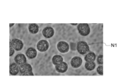
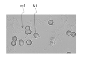
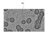
- This is a microscopic image of cyanobacteria obtained in verification 3.
- This is a microscopic image of cyanobacteria obtained in verification 3.
- FIG. 1 is a conceptual diagram showing an example of an embodiment of a proliferation inhibition method.
- 2 is a schematic diagram showing a configuration of the lighting device when viewed in a direction parallel to a main surface of an ultraviolet exit window.
- FIG. 2 is a block diagram illustrating a schematic configuration of a lighting device.
- 14 is a conceptual diagram showing a schematic arrangement of an ultraviolet ray source and an illumination light source when the illumination device shown in FIG. 13 is viewed from a direction perpendicular to the ultraviolet ray exit window.
- FIG. 12 is a diagram showing the fossil as viewed from the lighting device.
- FIG. 1 is a conceptual diagram showing an example of an embodiment of a proliferation inhibition method.
- FIG. 17B is a view of FIG. 17A from a different angle.
- FIG. 13 is a perspective view showing a modified example of the ultraviolet irradiation device.
- 19 is a diagram showing the ultraviolet irradiation device as viewed from a different direction than that of FIG. 18.
- FIG. 19B is a diagram showing a state in which the emission direction of ultraviolet light is changed from the state of FIG. 19A.
- FIG. 19 is a block diagram showing a schematic configuration of the ultraviolet irradiation device 1 according to FIG. 18.
- FIG. 21 is a graph showing the results of verification 4. This is a phase contrast microscope image of cyanobacteria obtained in verification 5. This is a phase contrast microscope image of cyanobacteria obtained in verification 5. This is a phase contrast microscope image of cyanobacteria obtained in verification 5.
- FIG. 1 is a conceptual diagram showing a typical embodiment of a proliferation inhibition method.
- FIG. 11 is a block diagram showing a schematic configuration of another ultraviolet irradiation device.
- FIG. 11 is a block diagram illustrating a schematic configuration of another lighting device.
- Fig. 1A is a conceptual diagram showing an example of an embodiment of the growth inhibition method.
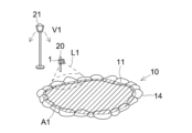
- Fig. 1A shows a scene in which ultraviolet light L1 emitted from an ultraviolet light irradiation device 1 is irradiated onto a pond 10 partitioned by stones 14 or the like.
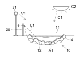
- FIG. 1B is a conceptual diagram that shows a different scene from FIG. 1A. As shown in FIG. 1B, in a scene where sunlight C1 is not irradiated, such as at night, visible light V1 is irradiated from the lighting devices 21 for the purpose of illuminating the surroundings, etc.
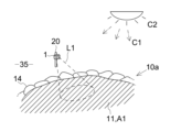
- FIG. 2 is a drawing of FIG. 1A viewed from a different angle. As mentioned above, it is assumed that the lighting device 21 is turned off during the time period when sunlight C1 is irradiated, but for convenience of illustration, FIG. 2 shows both the visible light V1 emitted by the lighting device 21 and the sunlight C1.
- FIG. 1A sunlight C1 is irradiated onto the pond 10.
- FIG. 1B visible light V1 is irradiated onto the pond 10.
- the pond 10 contains water, and carbon dioxide in the air and water. Therefore, algae and the like live and grow in the pond 10. More specifically, microorganisms such as cyanobacteria live and grow on the surfaces of the stones 14, on the water surface 11 of the pond 10, and in the water. Also, algae that have taken root on the stones 14 and the like live and grow on the bottom surface 12 of the pond 10.
- FIG. 1A, FIG. 1B, and FIG. 2 the habitat area A1 of the algae and the like in the pond 10 is shown diagrammatically, and the area corresponding to the habitat area A1 is hatched.
- ultraviolet light L1 is irradiated onto the stone 14 and the water surface 11 in the vicinity of the stone 14. If algae or the like grows on the surface of the stone 14, the surface of the stone 14 becomes slippery. Therefore, from the viewpoint of safety for people visiting the pond 10, it is preferable to irradiate the stone 14 with ultraviolet light L1.
- the habitat area A1 is not limited to the stones 14 and the water surface 11 of the pond 10, but also includes the surfaces of the stones 14 forming the bottom surface 12 of the pond 10, as well as the surfaces of sand and pebbles, etc., so ultraviolet light L1 may be irradiated onto these.
- the ultraviolet rays L1 emitted by the ultraviolet irradiation device 1 are in the wavelength range of 200 nm to 230 nm. As described below, by irradiating the habitat area A1 of algae with ultraviolet rays L1 in the above wavelength range, the proliferation of algae and the like is suppressed. Furthermore, sufficient irradiation of ultraviolet rays breaks down the chlorophyll of the algae and the like present in the pond 10, reducing the areas discolored green by the algae and the like, and restoring the beauty of the pond 10.
- the water in the pond 10 also convects due to naturally occurring wind and temperature gradients in the water. Therefore, as shown in FIG. 1A, even if the area irradiated with ultraviolet light L1 is only part of the water surface 11, it is expected that the convection of the water in the pond 10 will suppress the proliferation of algae and the like over a wide area of the water surface 11. Naturally, ultraviolet light L1 may also be irradiated onto the entire water surface 11.
- chlorophyll is broken down because irradiation with ultraviolet light L1 breaks down algae, etc., causing chlorophyll to flow out of the algae, etc., and then ultraviolet light L1 is irradiated onto the chlorophyll.
- ultraviolet light L1 breaks down algae, etc.
- the outflow of chlorophyll is promoted by water convection, making it easier for ultraviolet light L1 to be irradiated onto the chlorophyll.
- chlorophyll is diluted as it flows out over a wide area due to water convection. In this way, irradiating water storage areas with ultraviolet light L1 has a large aesthetic restoration effect and is therefore ideal.
- lighting devices 21 are installed around the pond 10, but algae and the like grow due to at least the visible light contained in sunlight C1. In other words, whether or not lighting devices 21 are installed around the pond 10 is optional.
- the configuration of the ultraviolet irradiation device 1 is explained below.
- FIG. 3 is an enlarged view of the periphery of the ultraviolet irradiation device 1 in FIG. 1A.
- FIG. 4A is a schematic diagram showing the configuration of the ultraviolet irradiation device 1 when viewed from the axial direction of a lamp constituting the ultraviolet source 2 described below.
- FIG. 4B is a schematic diagram showing the configuration of the ultraviolet irradiation device 1 when viewed from a direction perpendicular to the main surface of the ultraviolet exit window 4.
- the interior of the ultraviolet irradiation device 1 is shown in a transparent manner in FIGS. 4A and 4B.
- the ultraviolet irradiation device 1 comprises an ultraviolet source 2, a housing 3, an ultraviolet exit window 4, and an attachment portion 5.
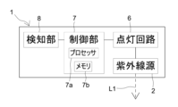
- FIG. 5 is a block diagram showing a schematic configuration of the ultraviolet irradiation device 1. As shown in FIG. 5, the ultraviolet irradiation device 1 includes a lighting circuit 6, a control unit 7, and a detection unit 8.
- the ultraviolet light source 2 is composed of a straight tube excimer lamp containing krypton gas and chlorine gas as the light emitting gas, and emits ultraviolet light L1 with a wavelength of 200 nm to 230 nm.
- the pond 10 is home to fish and other living organisms (not shown), and as mentioned above, by using ultraviolet light L1 in the above wavelength range, it is possible to irradiate the pond 10 with ultraviolet light while reducing the impact on the ecosystem.
- the ultraviolet light source 2 only needs to be capable of emitting ultraviolet light L1 of the above wavelength, and may be composed of a solid-state light source such as an LED or LD.
- the dominant wavelength of ultraviolet light L1 belongs to the above wavelength range.
- “dominant wavelength” refers to a wavelength range that shows a light intensity of 40% or more of the light intensity of the wavelength (peak wavelength) that shows the maximum intensity on the emission spectrum, and includes the peak wavelength.
- the housing 3 houses the ultraviolet light source 2 inside.
- the ultraviolet light L1 is extracted to the outside from an ultraviolet light exit window 4 of the housing 3 (see FIG. 4A).
- a diffusion filter that diffuses and transmits the incident ultraviolet light L1 may be mounted on the main surface of the ultraviolet light exit window 4.
- a fluororesin sheet such as PTFE can be used.
- an optical filter that suppresses the transmission of ultraviolet light on the wavelength side longer than 230 nm may be mounted on the main surface of the ultraviolet light exit window 4.
- an optical filter that suppresses the transmission of ultraviolet light with wavelengths between 240 nm and 300 nm is used.
- “suppressing transmission” refers to lowering the ratio of the light intensity of ultraviolet light with wavelengths longer than 230 nm to the light intensity of ultraviolet light within the wavelength range of 200 nm to 230 nm that has passed through the optical filter.
- the optical filter is, for example, a dielectric multilayer film in which a thin film layer of silica (SiO 2 ) and a thin film layer of hafnia (HfO 2 ) are laminated.
- the housing 3 in this embodiment is waterproofed. More specifically, the housing 3 has seams 3a around its periphery, and these seams 3a are sealed by seal parts 3b made of resin such as silicone (see FIG. 4B). As the seams 3a are sealed, the intrusion of moisture into the housing 3 is suppressed.
- FIG. 6A is a schematic diagram showing another example of the configuration of the ultraviolet irradiation device 1 when viewed from the axial direction of the lamp that constitutes the ultraviolet source 2.
- FIG. 6B is a schematic diagram showing another example of the configuration of the ultraviolet irradiation device 1 when viewed from a direction perpendicular to the main surface of the ultraviolet exit window 4.
- the ultraviolet irradiation device 1 may be configured to include a waterproof cover 3c that surrounds the periphery of the housing 3, as shown in FIGS. 6A and 6B.
- the waterproof cover 3c can be made mainly of, for example, a resin material or a metal material.
- main material refers to the material with the highest component ratio. More specifically, resin materials such as polyethylene, polypropylene, polyvinyl chloride, polystyrene, acrylonitrile-butadiene-styrene copolymer synthetic resin (ABS), acrylic, polyamide, polyacetal, polycarbonate, polyethylene terephthalate, polyphenylene sulfide, polysulfone, polyarylate, and fluororesin can be used as the resin material.
- Non-conductive fiber-reinforced resin materials such as FRP and carbon can also be used as the resin material.
- aluminum, iron, and stainless steel can be used as the metal material.
- FIG. 7A is a schematic diagram of the ultraviolet irradiation device 1 when it is attached to the pole 20.
- FIG. 7B is a schematic diagram of the ultraviolet irradiation device 1 attached to the pole 20 installed around the pond 10.
- the attachment portion 5 includes a clamping portion 5a, and the housing 3 is fixed to the pole 20 by the clamping portion 5a clamping the pole 20.
- the clamping portion 5a may be configured to include an elastic material on the surface that contacts the pole 20.
- elastic materials include rubber materials such as nitrile rubber, chloroprene rubber, ethylene propylene diene rubber (EPDM), and fluororubber.
- the mounting unit 5 may also be configured to be screwable to the pole 20. Furthermore, the mounting unit 5 may be configured to include an anchor that can be inserted into the ground, and to fix the housing 3 by inserting the anchor into the ground. In addition, the mounting unit 5 may include legs for adjusting the height of the ultraviolet light exit window 4.
- the lighting circuit 6 in this embodiment is an electric circuit configured to apply a voltage between a pair of electrodes (2a, 2b) of the excimer lamp, which is the ultraviolet light source 2 (see also FIG. 4B).
- the control unit 7 is a control means that transmits a control signal to the lighting circuit 6, and is configured to include a processor 7a, such as a CPU, and a memory 7b for storing information.
- the control unit 7 outputs a control signal to the lighting circuit 6 that controls the application of a voltage to light the ultraviolet light source 2 (see FIG. 5).
- the detection unit 8 is an illuminometer that measures the illuminance in the pond 10.
- the detection unit 8 issues a signal to the control unit 7 when it detects that the illuminance at the water surface 11 is equal to or greater than a predetermined reference value.
- the control unit 7 then controls the lighting circuit 6 based on the signal, thereby turning off the ultraviolet light source 2.
- the detection unit 8 may be, for example, an illuminance sensor made up of a semiconductor light-receiving element.
- the detection unit 8 measures the illuminance at the stone 14 or the water surface 11 by receiving visible light V1 reflected by the stone 14 or the water surface 11.
- the detection unit 8 may also be arranged independently outside the housing 3 and configured to transmit the measured illuminance data to the control unit 7 via wireless communication.
- the photosynthetic microorganisms that inhabit the pond 10 are, for example, cyanobacteria.
- Cyanobacteria tend to become less active in an environment where they are irradiated with visible light at an illuminance of 5000 [lx] or more.
- the reference value of illuminance is set to 5000 [lx]
- when visible light is irradiated with an illuminance of 5000 [lx] or more on the stone 14 the ultraviolet light source 2 is turned off and irradiation of ultraviolet light L1 is stopped.
- the activity of cyanobacteria becomes significantly less active in an environment where they are irradiated with visible light at an illuminance of 10000 [lx] or more.
- the reference value may be set to 10000 [lx].
- the ultraviolet light source 2 may be turned on.
- the detection unit 8 may also be configured to calculate the illuminance based on information stored in memory 7b included in the control unit 7. Information regarding the relationship between the illuminance around the ultraviolet irradiation device 1 and the illuminance at the stone 14 may be stored in advance in the memory 7b, and the detection unit 8 may measure the illuminance around the ultraviolet irradiation device 1 and calculate the illuminance at the stone 14 based on the information.
- the memory 7b may store in advance information regarding the relationship between the illuminance around the ultraviolet irradiation device 1 and the illuminance on the bottom surface 12 of the pond 10.
- the detection unit 8 measures the illuminance around the ultraviolet irradiation device 1 and calculates the illuminance on the bottom surface 12 based on the information.
- the irradiation range of the ultraviolet light L1 can be easily adjusted by changing the installation position of the ultraviolet light irradiation device 1 or by changing the emission direction of the ultraviolet light L1. In other words, by adjusting the irradiation range of the ultraviolet light L1, the proliferation of algae and the like over a wide area can be easily suppressed.
- the installation position of the ultraviolet light irradiation device 1 is arbitrary.
- the ultraviolet light irradiation device 1 may be attached to the support of the lighting device 21.
- FIG. 8 is a conceptual diagram showing a schematic diagram of the experimental system used in this verification.
- a sample liquid 41 to be verified was placed in a quartz cell 40 having an optical path length 43 of 10 mm.
- the sample liquid 41 in the cell 40 was irradiated with ultraviolet light L1 using an ultraviolet light irradiation device 44 described later.
- the ultraviolet light L1 was irradiated so that the irradiance at the end surface 42 of the cell 40 on the ultraviolet light irradiation device 44 side was 1 mW/ cm2 .
- the absorbance of the sample liquid 41 in the cell 40 was measured using an absorptiometer (Nanodrop, manufactured by Thermo Fisher Scientific). In this way, the effect of irradiation of the sample liquid 41 with ultraviolet light L1 on the sample liquid 41 was evaluated by checking the change in the absorbance of the sample liquid 41 relative to the integrated irradiance of the ultraviolet light L1.
- chlorophyll A manufactured by Fujifilm Wako Pure Chemical Industries, Ltd.: model number 034-21361 was used as the subject of verification.
- the sample solution 41 was prepared using acetonitrile (manufactured by Fujifilm Wako Pure Chemical Industries, Ltd.: model number 019-08631) as a solvent, with a chlorophyll A concentration of 10 ⁇ g/mL. 3 mL of sample solution 41 was placed in the cell 40.
- the ultraviolet irradiation device 44 that irradiates the ultraviolet light L1 was changed to vary the wavelength of the ultraviolet light L1, and the effect of irradiation with each ultraviolet light L1 on chlorophyll A was examined.
- this verification was carried out using an excimer lamp containing krypton gas and chlorine gas (UXFL70-222B4-UIA manufactured by Ushio Inc.) as the ultraviolet irradiation device 44, and a low-pressure mercury lamp (SUV-6 manufactured by AS ONE Corporation) as a comparative example.
- the excimer lamp used in this verification is equipped with an optical filter that limits the transmission of ultraviolet light in the range of 240 nm to 300 nm.
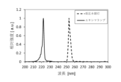
- Figure 9 is a graph showing the emission spectra of the excimer lamp and low-pressure mercury lamp used in this verification. Note that the emission spectra shown in Figure 9 are normalized based on the maximum emission intensity in each emission spectrum. As shown in Figure 9, for the excimer lamp used in this verification, the wavelength (peak wavelength) showing the maximum emission intensity is located near 222 nm. For the low-pressure mercury lamp, the peak wavelength is located near 254 nm. Note that "near” here is intended to include an error range of about 1 nm to 5 nm that can occur due to individual differences in the ultraviolet irradiation device 44.
- Verification 2 This verification differs from verification 1 in that cyanobacteria, which are microorganisms, were used as the subject of the verification. In addition, in consideration of the fact that cyanobacteria grow on the surface of stones 14 (see FIG. 1A, etc.), a cell 40 with an optical path length 43 of 2 mm was used in this verification. 0.3 mL of sample liquid 41 was poured into the cell 40.
- the cyanobacteria used in the verification were obtained through a distribution from the National Institute for Environmental Studies' Microbial Culture Collection (NIES Collection), which preserves a variety of microorganisms. More specifically, the strain number is NIES-44 and the scientific name is Microcystis aeruginosa.
- sample N1 The above-mentioned cyanobacteria (hereinafter, for convenience, referred to as "sample N1”) were cultured to prepare sample solution 41.
- Sample N1 was cultured in CB medium, also obtained from the NIES collection. The cultured sample was placed in an environment with an illumination of 1200 [lx] for 10 hours per day, and in an environment with an illumination of 100 [lx] or less for the remaining 14 hours. The temperature during culture was also set to 25 degrees. The solution cultured under these conditions for 20 days was used as sample solution 41.
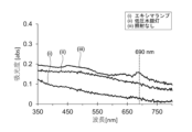
- FIG. 10A is a graph showing the integrated irradiance of ultraviolet light L1 on the horizontal axis and the absorbance of the sample liquid 41 on the vertical axis.
- the absorbance is a value normalized by the absorbance of the sample liquid 41 before the irradiation of ultraviolet light L1 is started.
- FIG. 10A shows the results when an excimer lamp and a low-pressure mercury lamp are used as the ultraviolet light irradiation device 44.
- FIG. 10A also shows the absorbance in a state where ultraviolet light L1 is not irradiated (no irradiation) as a reference example.
- FIG. 10A shows the absorbance for light of 670 nm.
- Chlorophyll A is one of the pigments found in microorganisms that perform photosynthesis, such as algae and cyanobacteria. Chlorophyll A also plays a role in photosynthesis, such as absorbing visible light V1 and converting the light energy. Therefore, it is believed that the activity of algae, etc. decreases due to the decrease in chlorophyll A. In other words, it can be said that the proliferation of algae, etc. is inhibited by irradiation with ultraviolet light L1.
- FIG. 10B is an absorption spectrum of the sample solution 41 of the sample N1 used in this verification.
- FIG. 10B shows the absorption spectrum of the sample solution 41 before (without) irradiation with ultraviolet light L1 and when the integrated irradiance of ultraviolet light L1 is set to 16 J/cm 2.
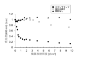
- FIG. 10C is a graph showing the results of verification 2, following FIG. 10A.
- the sample N1 has a characteristic absorption peak of absorbance near 690 nm.
- the absorption peak is estimated to be an absorption band related to the chlorophyll contained in the sample N1, and the decrease due to irradiation with ultraviolet light L1 was significant. Therefore, FIG. 10C shows the absorbance for light of 690 nm.
- irradiation with ultraviolet light L1 reduced the absorbance of sample liquid 41 for visible light (350 nm to 800 nm). From this result, it is believed that the transmittance of sample N1 in sample liquid 41 for visible light has increased. In other words, irradiation with ultraviolet light L1 has the effect of diluting the color exhibited by sample N1. Furthermore, this decrease in absorbance was more significant when ultraviolet light L1 was irradiated using an excimer lamp than when ultraviolet light L1 was irradiated using a low-pressure mercury lamp.
- FIG. 10C The same discussion as in FIG. 10A is possible for FIG. 10C. That is, it was confirmed that, like chlorophyll A, sample N1 was reduced by irradiation with ultraviolet light L1. More specifically, from FIG. 10C, it can be seen that in the case of using an excimer lamp, the absorbance rapidly decreased from the start of irradiation with ultraviolet light L1 until the integrated irradiance reached 1 J/ cm2 , and the absorbance decreased more significantly than in the other cases. On the other hand, in the case of using a low-pressure mercury lamp, the absorbance decreased gradually, and even if the integrated irradiance reached 10 J/ cm2 , the absorbance decrease was small.
- the integrated irradiance at which the absorbance shows 0.1 compared to the state before irradiation with ultraviolet light L1 is 0.5 J/ cm2 in the case of an excimer lamp, while it is 12 J/ cm2 in the case of a low-pressure mercury lamp.
- the latter requires an integrated irradiance 20 times or more that of the former.
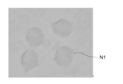
- Fig. 11A is a microscopic image of the cyanobacteria contained in the sample liquid 41 before irradiation with ultraviolet light L1
- Fig. 11B is a microscopic image of the cyanobacteria contained in the sample liquid 41 when the integrated irradiance was set to 56 mJ/ cm2
- Fig. 11C is a microscopic image when the integrated irradiance was set to 1.3 J/ cm2 .
- the ultraviolet rays emitted by the excimer lamp used in this verification have a peak wavelength near 222 nm, and fall within the range of 200 nm to 230 nm.
- the ultraviolet rays emitted by the low-pressure mercury lamp used in this verification have a peak wavelength near 254 nm, and fall within the range of 250 to 260 nm.
- ultraviolet rays in the range of 200 nm to 230 nm are more effective at decomposing chlorophyll A and sample N1 than ultraviolet rays in the range of 250 to 260 nm.
- example N1 a species of cyanobacteria identified by the strain number NIES-44 was used.
- example N1 a species of cyanobacteria identified by the strain number NIES-44 was used.
- ultraviolet light L1 in the range of 200 nm to 230 nm is effective in decomposing chlorophyll A.
- chlorophyll A is found in many algae, it is presumed that irradiation with the above ultraviolet light L1 inhibits the growth of not only sample N1 used in verification 2, but also algae such as euglena algae and green algae, and other microorganisms that perform photosynthesis.
- the excimer lamp used in this verification is a light source that emits ultraviolet light L1 with a dominant wavelength in the range of 200 nm to 230 nm, as shown in Figure 9.
- the ultraviolet light L1 contains ultraviolet light that falls within the above wavelength range
- the dominant wavelength is outside the above wavelength range
- the proliferation of algae, etc. can be suppressed, as in this verification, by adjusting the output of the ultraviolet light irradiation device that emits the ultraviolet light L1 and the irradiation time of the ultraviolet light L1, etc., so that the habitat of the algae, etc. is sufficiently irradiated with ultraviolet light in the above wavelength range.
- the end surface 42 of the cell 40 was irradiated with a radiant illuminance of 1 mW/ cm2 .
- the irradiant illuminance may be appropriately adjusted in consideration of the effect of the irradiation of the ultraviolet ray L1 on the irradiation target.
- the aesthetic appearance of the irradiation object does not change suddenly between the area irradiated with the ultraviolet ray L1 and the area not irradiated with the ultraviolet ray.
- the ultraviolet ray may be irradiated so that the integrated irradiance of the ultraviolet ray is 1 J/cm 2 or more at the time when one week has elapsed since the start of irradiation of the ultraviolet ray L1, or the integrated irradiance of the ultraviolet ray is 1 J/cm 2 or more at the time when 12 weeks have elapsed.
- the ultraviolet ray L1 may be irradiated so that the integrated irradiance at the time when a predetermined period set within a period of one week to 12 weeks has elapsed is 1 J/cm 2 or more.
- the ultraviolet ray L1 may be irradiated intermittently.
- ultraviolet light may be irradiated so that the integrated irradiance is 1 J/ cm2 or more within a period shorter than one week, for example, three days after the start of irradiation of ultraviolet light L1.
- a program such as the voltage to be supplied to the ultraviolet light source 2 and the supply time of the voltage may be stored in the memory 7b (see FIG. 5).
- the program is for driving the ultraviolet light source 2 so that a preset integrated irradiance of the ultraviolet light L1 is reached within a predetermined period of time from the start of irradiation of the ultraviolet light L1.
- the control unit 7 may be configured to output a control signal to the lighting circuit 6 based on the program.
- FIG. 12 is a conceptual diagram showing a typical embodiment of the growth inhibition method.
- a scene is shown in which visible light V1 and ultraviolet light L1 emitted from a lighting device 30 are irradiated onto a fossil 15 on a display stand 16 exhibited in a museum.
- the fossil 15 may have algae or microorganisms attached to its surface. It is also expected that algae etc. may attach to or grow on the surface of the fossil 15 during transportation after excavation or during the long-term display process. If algae etc. attach to or grow on the surface of the fossil 15 and grow, the surface will turn green, damaging the aesthetic appearance of the fossil 15. It is also preferable to suppress the growth of algae etc. from the perspective of maintaining a good preservation condition of the fossil 15.
- This embodiment differs from the first embodiment in that the lighting device 30 irradiates ultraviolet light L1 onto the habitat area A1 of the fossil 15.
- FIG. 13 is a schematic diagram showing the configuration of the lighting device 30.
- the lighting device 30 includes an ultraviolet light source 2, an illumination light source 9, a housing 3, an ultraviolet light exit window 4, and a connector 22.
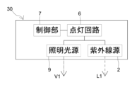
- FIG. 14 is a block diagram showing a schematic configuration of the lighting device 30. As shown in FIG. 14, the lighting device 30 includes a lighting circuit 6 and a control unit 7.
- the ultraviolet light source 2 and the illumination light source 9 are composed of solid-state light sources such as LED elements.
- the illumination device 30 is capable of emitting ultraviolet light L1 and visible light V1, and therefore illuminates the fossil 15 and irradiates the fossil 15 with ultraviolet light L1.
- the irradiation of ultraviolet light L1 inhibits the growth of algae and the like on the surface of the fossil 15, so there is no risk of damaging the surface of the fossil 15 compared to directly cleaning the surface with a brush or the like.
- the illumination device 30 with both the ultraviolet light source 2 and the illumination light source 9, the space required for installing both can be reduced.
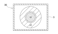
- FIG. 15 is a conceptual diagram showing the arrangement of the ultraviolet light source 2 and the illumination light source 9 when the illumination device 30 shown in FIG. 13 is viewed from a direction perpendicular to the main surface of the ultraviolet light exit window 4.
- the area where the ultraviolet light source 2 is arranged is referred to as the "ultraviolet light source arrangement area 31," and that of the illumination light source 9 is referred to as the "illumination light source arrangement area 32.”
- FIG. 16 corresponds to a drawing of the fossil 15 when viewed from the illumination device 30 in FIG. 12.
- a lighting device 30 is realized in which the range irradiated with ultraviolet light L1 (hereinafter, for convenience, referred to as the "ultraviolet light irradiation range L2") includes the visible light irradiation range V2 inside, as shown in FIG. 16.
- the irradiation ranges of ultraviolet light L1 and visible light V1 are shown diagrammatically. Note that in FIG. 16, the visible light irradiation range V2 and the ultraviolet light irradiation range L2 are illustrated overlapping, and ultraviolet light L1 is also irradiated onto the visible light irradiation range V2. This is because the ultraviolet light L1 emitted from the ultraviolet light source 2 travels while spreading out at a predetermined divergence angle.
- the ultraviolet light L1 is irradiated to an area that includes the visible light irradiation range V2.
- the housing 3 houses the ultraviolet light source 2 and the illumination light source 9 inside.
- the ultraviolet light L1 is extracted to the outside from the ultraviolet light exit window 4 of the housing 3.
- the ultraviolet light exit window 4 also functions as a visible light exit window for extracting the visible light V1 emitted by the illumination light source 9 to the outside of the housing 3.
- an optical filter and a diffusion filter may be mounted on the main surface of the ultraviolet light exit window 4, as described above in the first embodiment.
- the lighting device 30 is installed indoors, so there is a low possibility that moisture will infiltrate the inside of the housing 3. Therefore, there is no need to apply waterproofing treatment to the housing 3.
- the lighting circuit 6 shown in FIG. 14 is an electrical circuit that supplies the power required for lighting to the ultraviolet light source 2 and the illumination light source 9.
- the control unit 7 is a control means that transmits a control signal to the lighting circuit 6.
- the control unit 7 is configured to turn on the ultraviolet light source 2 while the illumination light source 9 is off.
- the control unit 7 is preferable to irradiate ultraviolet light L1 during the period when the illumination light source 9 is off.
- the period when the illumination light source 9 is off refers to, for example, the non-operating hours of the museum. In other words, during that time period, there is a low possibility that people will be present within the facility. Therefore, if ultraviolet light L1 is irradiated during that time period, the standard values of the ACGIH and other standards mentioned above can be easily complied with.
- the connector 22 is electrically connected to a power supply terminal provided on the ceiling 23. The necessary power is supplied to the lighting circuit 6 via the connector 22.
- the lighting device 30 may be attached to a ceiling 23, a wall surface, etc. by including the mounting portion 5 described above in the first embodiment.
- FIG. 13 shows an example in which the ultraviolet light exit window 4 also functions as a visible light exit window
- the ultraviolet light source 2 and the illumination light source 9 may be disposed in separate spaces within the housing 3, and the ultraviolet light L1 and the visible light V1 may be emitted to the outside from different locations.
- the arrangement of the ultraviolet light source 2 and the illumination light source 9 may also be designed arbitrarily.
- control unit 7 has been described as turning on the ultraviolet light source 2 while the illumination light source 9 is turned off (see FIG. 14).
- the control unit 7 and the lighting circuit 6 may be configured for each of the ultraviolet light source 2 and the illumination light source 9, and the ultraviolet light source 2 and the illumination light source 9 may be turned on or off individually.
- the lighting device 30 has been described as including an ultraviolet light source 2 and an illumination light source 9.
- an ultraviolet light irradiation device 1 including an ultraviolet light source 2 may be installed separately from the lighting device that illuminates the fossil 15.
- FIG. 17A is a conceptual diagram showing a schematic example of one embodiment of the proliferation inhibition method.
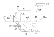
- FIG. 17B is a drawing of FIG. 17A viewed from a different angle, following FIG. 2.
- FIGS. 17A and 17B show a scene in which ultraviolet light L1 emitted by the ultraviolet light irradiation device 1 is irradiated toward the water surface 11 of the lake 10a.
- FIG. 17A shows a habitat area A1 formed on the water surface 11 of the lake 10a.
- oxygen includes the oxygen in the water, so the occurrence of blue-green algae reduces the oxygen concentration in the water.
- cyanobacteria may produce microcystin, which is toxic to living organisms. Therefore, if blue-green algae occurs in lake 10a, the cyanobacteria that form the algae will produce a large amount of microcystin, greatly affecting the ecosystem of lake 10a.
- Lake 10a can be a target for people to view, but if the foul odor becomes too noticeable, it can discourage people from viewing it.
- the water surface 11 it is preferable to irradiate the water surface 11 with ultraviolet light L1 to reduce, i.e., decompose, the cyanobacteria and inhibit their proliferation.
- ultraviolet light L1 decomposes and reduces algae, etc., including cyanobacteria, and inhibits the proliferation of the algae, etc.
- the microcystin produced by the cyanobacteria may flow into lake 10a and remain there. However, as described below, it is possible to decompose the microcystin by irradiation with ultraviolet light L1.
- UV-L1 irradiation can decompose cyanobacteria while suppressing the consumption of oxygen in the water and the generation of foul odors.
- the integrated irradiance of the ultraviolet light L1 at the water surface 11 is 200 mJ/ cm2 or more.
- the integrated irradiance of the ultraviolet light L1 can be adjusted by varying the lighting time of the ultraviolet irradiation device 1 and the irradiance at the water surface 11.
- the irradiance at the water surface 11 can be calculated based on the distance between the ultraviolet light exit window 4 and the water surface 11, for example, using the irradiance at the ultraviolet light exit window 4 of the ultraviolet irradiation device 1 as a reference.
- FIG. 17B shows a schematic diagram of domestic wastewater 36 flowing into lake 10a from land 35.
- the nitrogen concentration or phosphorus concentration is likely to become locally high, particularly near the water's edge 38 of lake 10a, and that cyanobacteria are likely to proliferate and cause blue-green algae.
- the ultraviolet irradiation range L2 of ultraviolet light L1 on the water surface 11 be formed within a distance D1 of 20 m, more preferably 10 m, from the water's edge 38 of lake 10a.
- the configuration of the ultraviolet irradiation device 1 can be discussed in the same manner as described in the first embodiment.
- FIG. 18 is a perspective view showing a modified example of the ultraviolet irradiation device 1. As shown in FIG. 18, the ultraviolet irradiation device 1 may be equipped with a wind vane 50, which will be described later.
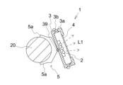
- FIG. 19 is a drawing of the ultraviolet irradiation device 1 viewed from a different direction than FIG. 18.
- the inside of the ultraviolet irradiation device 1 is shown in a transparent manner, and the anemometer 50 is omitted.
- the mounting part 5 of the ultraviolet irradiation device 1 includes a clamping part 5a and an angle adjustment mechanism 39, as shown in FIG. 19. This allows the mounting part 5 to be configured to change the direction of the ultraviolet light L1 emitted by the housing 3.
- the angle adjustment mechanism 39 is fixed to a portion of the housing 3 and is configured to be able to change the position of the housing 3 relative to the pole 20.
- FIG. 19B is a diagram showing a state in which the emission direction of ultraviolet light L1 has been changed from the state of FIG. 19A. As shown in FIG. 19B, the angle adjustment mechanism 39 changes the position of the housing 3 relative to the pole 20 by, for example, driving an electric motor (not shown), thereby changing the emission direction of ultraviolet light L1. Note that the emission direction of ultraviolet light L1 may be a direction perpendicular to the ultraviolet light exit window 4.
- the wind vane 50 comprises a fixed base 51, a body 52, and a support shaft 53 that supports the body 52.
- the body 52 has a shape that extends in one direction, and has wings (52a, 52b) and a tip 52c on the opposite side.
- the support shaft 53 is connected to the fixed base 51 and supports the body 52 in a rotatable state within a horizontal plane.
- the anemometer 50 detects the wind direction by detecting the orientation of the body 52 with a sensor (not shown) built into the fixed base 51.
- the emission direction of ultraviolet light L1 may be changed based on the wind direction detected by the anemometer 50.
- FIG. 20 is a block diagram that, following FIG. 5, shows a schematic configuration of the ultraviolet irradiation device 1 according to FIG. 18.
- the control unit 7 is configured to be able to transmit a signal d2 for driving the angle adjustment mechanism 39 to the angle adjustment mechanism 39 based on a signal d1 from the wind vane 50.
- the angle adjustment mechanism 39 changes the position of the housing 3 relative to the pole 20, for example as described with reference to FIG. 19B, to change the emission direction of the ultraviolet light L1.
- the emission direction of ultraviolet rays L1 set for each wind direction may be stored in advance in the memory 7b of the control unit 7.
- the control unit 7 reads out the emission direction of ultraviolet rays L1 corresponding to the wind direction measured by the anemometer 50, and transmits it as a signal d2 to the angle adjustment mechanism 39.
- the angle adjustment mechanism 39 changes the position of the housing 3 relative to the pole 20, and changes the emission direction of ultraviolet rays L1 to a predetermined direction.
- the configuration of the angle adjustment mechanism 39 is arbitrary as long as it can change the emission direction of the ultraviolet light L1, and is not limited to the configuration described with reference to Figures 19A and 19B.
- the wind vane 50 can have a conventionally known configuration as long as it can measure the wind direction.
- the control unit 7 that controls the lighting circuit 6 and the angle adjustment mechanism 39 does not have to be a common unit. Also, in the above description, the control unit 7 controls the angle adjustment mechanism 39, but the emission direction of the ultraviolet light L1 may be changed manually.
- the wind direction may be measured by any wind vane.
- information about the wind direction may be sent to any server.
- the control unit 7 may receive information about the wind direction from any server.
- the ultraviolet light irradiation device 1 when changing the emission direction of the ultraviolet light L1 according to the wind direction, the ultraviolet light irradiation device 1 is not limited to being equipped with the wind vane 50.
- control unit 7 may transmit information regarding the emission direction of ultraviolet light L1 from any server.
- the control unit 7 is not limited to a configuration including memory 7b.
- the ultraviolet irradiation device 1 is described as being attached to the poles 20 installed around the lake 10a. However, it is also possible to install the ultraviolet irradiation device 1 above the water of the lake 10a, for example, by driving the poles 20 into the bottom surface 12 of the lake 10a.
- multiple ultraviolet irradiation devices 1 may be placed around the lake 10a or on the water, and information regarding the emission direction of ultraviolet rays L1 may be transmitted from an arbitrary server to each ultraviolet irradiation device 1 based on the wind direction.
- the habitat area A1 has been described as the water surface 11 of the lake 10a.
- a water storage area such as a pond 10, for example.
- Verification 4 The effect of irradiating microcystin with ultraviolet light L1 was verified, and will be described below as Verification 4. In this verification, microcystin was irradiated with ultraviolet light L1 under two conditions, Case 1 and Case 2, and the residual rate of microcystin was evaluated.
- the procedure for preparing the sample subjected to irradiation with ultraviolet light L1 is as follows. First, microcystin (Fujifilm Wako Pure Chemical Industries, Ltd.: 136-12241 Microcystin LR) was dissolved in methanol (Fujifilm Wako Pure Chemical Industries, Ltd.: 131-01826) at a concentration of 250 ⁇ g/mL. Next, this solution was diluted and mixed with pure water to obtain a sample solution with a concentration of approximately 1600 pg/mL. Then, approximately 4 mL of this sample solution was dropped into a petri dish with a diameter of 35 mm to obtain a sample.
- the sample was irradiated with ultraviolet light L1.
- a plurality of samples were prepared, and the reactivity of the samples was evaluated by a known ELISA method with different integrated irradiances (mJ/cm 2 ) of ultraviolet light L1.
- the ELISA method is a method for evaluating the reactivity of microcystin by reacting microcystin with a specific antibody and measuring the absorbance of the reaction product.
- an "ELISA kit Tokiwa Chemical Industry Co., Ltd.: 300-05191 Microcystin ELISA Kit)" for evaluating microcystin was used as the kit for carrying out the ELISA method.
- the residual rate of microcystin was evaluated from the ratio of the absorbance of the sample after UV-L1 irradiation to the absorbance of the sample before UV-L1 irradiation.
- the ultraviolet light L1 was irradiated using an excimer lamp filled with krypton gas and chlorine gas.
- the sample was irradiated with ultraviolet light L1, whose peak wavelength is located near 222 nm.
- the excimer lamp used in this verification has the same specifications as the excimer lamp used in the aforementioned verification 1.
- Results of Verification 4 is a graph showing the results of verification 4.
- the residual rate of microcystin versus the integrated irradiance (mJ/cm 2 ) of ultraviolet light L1 in case 1 and case 2 is shown.
- the residual rate of microcystin decreases as the cumulative irradiance of ultraviolet light L1 increases.
- Fig. 21 clearly shows that irradiation with ultraviolet light L1 decomposes microcystin.
- the cumulative irradiance required for the residual rate to reach, for example, about 0.1 is 200 mJ/ cm2 .
- the residual rate remained at about 0.2 even when the cumulative irradiance reached 1000 mJ/ cm2 .
- irradiation with an excimer lamp is more effective at decomposing microcystin than irradiation with a low-pressure mercury lamp.
- the ultraviolet light emitted by the excimer lamp used in this verification has a peak wavelength near 222 nm, with a dominant wavelength in the range of 200 nm to 230 nm.
- the dominant wavelength of the ultraviolet light L1 it is preferable for the dominant wavelength of the ultraviolet light L1 to be in the range of 200 nm to 230 nm. This point will be reconsidered later, including the results of verification 5.
- microcystin can be decomposed favorably.
- the ultraviolet rays L1 are irradiated so that the integrated irradiance at the time of the lapse of a predetermined period set within 72 hours is 200 mJ/cm 2 or more. Note that the period required for the integrated irradiance to reach 200 mJ/cm 2 after the start of irradiation of the ultraviolet rays L1 can be appropriately adjusted.
- ultraviolet rays may be irradiated so that the integrated irradiance of the ultraviolet rays is 200 mJ/cm 2 or more after 48 hours have elapsed from the start of irradiation of the ultraviolet rays L1, or ultraviolet rays may be irradiated so that the integrated irradiance of the ultraviolet rays is 200 mJ/cm 2 or more after 24 hours have elapsed.
- phase contrast observation was performed. More specifically, the inverted microscope used in Verification 3 and this verification allows switching between phase contrast observation mode and bright field observation mode. In phase contrast observation, the contrast between light and dark allows for more detailed observation of the cell membrane of microorganisms, etc. It should be noted that, just to be clear, in the above Verification 3, sample N1 was observed in bright field observation mode in order to observe the color change exhibited by sample N1.
- cyanobacteria (sample N1) were observed under two different conditions: irradiating ultraviolet light from an excimer lamp, as in verification 3, and irradiating ultraviolet light from the low-pressure mercury lamp used in verification 1, etc.
- Fig. 22A is a phase contrast microscope image of sample N1 before irradiation with ultraviolet light L1.
- Fig. 22B is a phase contrast microscope image of sample N1 at the time when ultraviolet light was irradiated by an excimer lamp having the same specifications as in verification 3 and the integrated irradiance was set to 75 mJ/ cm2 .
- Fig. 22C is a phase contrast microscope image of sample N1 at the time when ultraviolet light was irradiated by a low-pressure mercury lamp and the integrated irradiance was set to 750 mJ/ cm2 .
- FIG. 22B when ultraviolet light emitted by the excimer lamp, i.e., ultraviolet light having a peak wavelength near 222 nm, was irradiated, the outer shape of sample N1 changed compared to the state before ultraviolet light irradiation (Fig. 22A). This is believed to be because the cell membrane of sample N1 was broken by ultraviolet light irradiation. Also, in Fig. 22A, component m1, which is presumed to have flowed out from sample N1, was observed. As described above, in Fig.
- the integrated irradiance of ultraviolet light was set to 75 mJ/ cm2 , and this result is consistent with the point that the color exhibited by sample N1 became lighter at an integrated irradiance of about 50 mJ/ cm2 (see Fig. 11B).
- Fig. 22B more clearly shows that the cell membrane of the cyanobacteria breaks and decomposition starts at an integrated irradiance of about 50 mJ/ cm2 .
- the decomposition of the cyanobacteria causes pigments such as chlorophyll and microcystin to leak out of the cyanobacteria.
- Fig. 22C when ultraviolet light emitted by a low pressure mercury lamp, i.e., ultraviolet light having a peak wavelength near 254 nm, was irradiated, no change was observed in sample N1 compared to the state before ultraviolet light irradiation (Fig. 22A).
- the integrated irradiance is about 10 times that of Fig. 22B.
- ultraviolet light having a peak wavelength near 254 nm was irradiated, it is considered that sample N1 was hardly decomposed even if the integrated irradiance was 750 mJ/ cm2 . This point is consistent with the result of Fig. 10C.
- proteins have a very high absorption coefficient for ultraviolet light in the wavelength range of 200 nm to 230 nm. More specifically, proteins are known to have a high absorption coefficient for ultraviolet light with wavelengths of approximately 240 nm or less. On the other hand, proteins have a relatively low absorption coefficient for ultraviolet light with a wavelength of, for example, 254 nm.
- the cell membrane of cyanobacteria is composed of proteins, it is believed to have a higher absorption coefficient for ultraviolet light with a peak wavelength around 222 nm than for ultraviolet light with a peak wavelength around 254 nm. This is believed to be the reason why irradiation with ultraviolet light from the excimer lamp was more effective at decomposing cyanobacteria.
- microcystin which is composed of proteins, also exhibits a high absorption coefficient for ultraviolet light in the above wavelength range.
- the dominant wavelength of ultraviolet light L1 be in the range of 200 nm to 230 nm.
- the cell membrane is composed of proteins not only in cyanobacteria but also in other algae. Also, since the chlorophyll contained in algae exists in a state bound to a certain protein, the reduction of chlorophyll is promoted by the decomposition of the protein. In other words, from the viewpoint of inhibiting the proliferation of algae and protecting or restoring the beauty of the plant, it is preferable that the dominant wavelength of ultraviolet light falls within the above wavelength range.
- FIG. 22 is a conceptual diagram showing a typical example of an embodiment of the proliferation inhibition method. As shown in Fig. 22, ultraviolet light L1 may be irradiated onto an exterior wall surface 25, such as under the eaves of a building 24.
- an ultraviolet irradiation device 1 may be attached to the exterior wall surface 25.
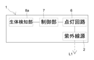
- FIG. 23A is a block diagram showing a schematic diagram of another configuration of the ultraviolet irradiation device 1.
- the ultraviolet irradiation device 1 may be equipped with a living organism detection unit 8a that detects the presence of a living organism such as a human in the vicinity.
- the living organism detection unit 8a is an infrared sensor that detects the surrounding heat.
- the living organism detection unit 8a issues a signal to the control unit 7 that it has detected the presence of a living organism in the vicinity.
- the control unit 7 then issues a signal to the lighting circuit 6 to turn off the ultraviolet ray source 2.
- the above-mentioned ACGIH and other regulations prescribe standard values for the amount of ultraviolet radiation irradiated to the human body.
- Ultraviolet radiation L1 which has a wavelength in the range of 200 nm to 230 nm, has an extremely low impact on the human body, but from the perspective of protecting the ecosystem, it is desirable to give some consideration to the amount of ultraviolet radiation irradiated to animals other than humans.
- the above-mentioned configuration makes it easy to irradiate ultraviolet radiation L1 in accordance with the above-mentioned ACGIH and other regulations.
- FIG. 23B is a block diagram showing a schematic diagram of another configuration of the lighting device 30.
- the control unit 7 receives the above signal from the biological detection unit 8a, it issues a signal to the lighting circuit 6 to turn off the ultraviolet light source 2 and turn on the illumination light source 9.
- the period during which the ultraviolet irradiation device 1 or the lighting device 30 irradiates the habitat area A1 with ultraviolet light L1 is not limited. Therefore, although the above description assumes that the ultraviolet irradiation device 1 or the lighting device 30 includes a control unit 7, it is optional whether or not the ultraviolet irradiation device 1 or the lighting device 30 includes a control unit 7.
- the detection unit 8 is not required.
- UV irradiation device 2 UV source 3: Housing 3a: Joint 3b: Sealing section 3c: Waterproof cover 4: UV exit window 5: Mounting section 6: Lighting circuit 7: Control section 7a: Processor 7b: Memory 8: Detection section 8a: Living organism detection section 9: Illumination light source 10: Pond 10a: Lake 11: Water surface 12: Bottom surface 14: Stone 15: Fossil 16: Display stand 20: Pole 21, 30: Illumination device 22: Connector 23: Ceiling 24: Building 25: Exterior wall surface 31: UV source placement area 32: Illumination light source placement area 35: Land 36: Domestic wastewater 37: Drain outlet 38: Water's edge 39: Angle adjustment mechanism 40: Cell 41: Sample liquid 42: End face 43: Optical path length 50: Wind vane 51: Fixed base 52: Body 52a, 52b: Wings 52c: Tip 53: Support axis A1: Habitat area C1: Sunlight C2: Sun L1: Ultraviolet light L2
Landscapes
- Life Sciences & Earth Sciences (AREA)
- Health & Medical Sciences (AREA)
- Epidemiology (AREA)
- Environmental Sciences (AREA)
- Veterinary Medicine (AREA)
- Engineering & Computer Science (AREA)
- Public Health (AREA)
- General Health & Medical Sciences (AREA)
- Animal Behavior & Ethology (AREA)
- Hydrology & Water Resources (AREA)
- Organic Chemistry (AREA)
- Chemical & Material Sciences (AREA)
- Water Supply & Treatment (AREA)
- Environmental & Geological Engineering (AREA)
- Toxicology (AREA)
- Marine Sciences & Fisheries (AREA)
- Animal Husbandry (AREA)
- Biodiversity & Conservation Biology (AREA)
- General Engineering & Computer Science (AREA)
- Micro-Organisms Or Cultivation Processes Thereof (AREA)
- Apparatus Associated With Microorganisms And Enzymes (AREA)
Abstract
容易に実行できる藻類又は微生物の増殖抑制方法を提供する。さらに、藻類等の増殖を容易に抑制できる紫外線照射装置、及び、周囲を照らすとともに、藻類等の増殖を容易に抑制できる照明装置を提供することを目的とする。 本発明に係る増殖抑制方法は、藻類又は光合成を行う微生物が生息している生息領域に対して、波長200nm~230nmの範囲に属する紫外線を照射することを特徴とする。
Description
本発明は、藻類又は光合成を行う微生物の増殖を抑制する、増殖抑制方法及び紫外線照射装置に関する。また、周囲を照らすとともに、藻類又は光合成を行う微生物の増殖を抑制する照明装置に関する。
従来、観光地や庭園等の人が鑑賞に訪れる場所、博物館において展示されている化石等において、藻類又は光合成を行う微生物が増殖することで、景観又は美観が損なわれるという問題がある。例えば、池などでは、藻類又は光合成を行う微生物が増殖すると、水が濁ったように見えてしまい、美観が損なわれる。
なお、「藻類」とは、例えば、ミドリムシ藻類、緑藻類又は珪藻類であり、その他に黄緑藻類、渦鞭毛藻類、紅藻類、褐藻類が挙げられる。また、「微生物」とは、例えば、真正細菌又は真核生物である。以下において、「藻類又は光合成を行う微生物」を「藻類等」と総称することがある。
上記の問題に対して、例えば下記特許文献1は、対象物に対して、藻類を防除又は藻類の発生を予防する塗料を塗布する方法を提案している。
上記特許文献1に係る方法を適用できれば、対象物における藻類等の増殖が抑制されると考えられる。しかし、この方法は、藻類等の増殖を抑制する塗料を塗布する方法であるため、池の水面や水中に存在する藻類等の増殖を抑制する場合には適用できない。また、新たに藻類等の発生が見られた場合には、その都度刷毛やノズル等を用いて塗料を塗布する作業を行う必要がある。さらに、作業者の手が届きにくい場所では、効率的に作業が行えない。
本発明は、上記事情に鑑み、容易に実行できる藻類等の増殖抑制方法を提供することを目的とする。また、本発明は、藻類等の増殖を容易に抑制できる紫外線照射装置、及び、周囲を照らすとともに、藻類等の増殖を容易に抑制できる照明装置を提供することを目的とする。
本発明に係る増殖抑制方法は、
藻類又は光合成を行う微生物が生息している生息領域に対して、主波長が波長200nm~230nmの範囲に属する紫外線を照射することを特徴とする。
藻類又は光合成を行う微生物が生息している生息領域に対して、主波長が波長200nm~230nmの範囲に属する紫外線を照射することを特徴とする。
藻類等は、池などの水面又は水中に浮遊した状態、又は物体表面に根付いた状態で生息する。そして、藻類等の光合成には可視光、水、及び二酸化炭素が利用される。つまり、藻類等の「生息領域」とは、水面、水中又は物体の表面であって、可視光、水、及び二酸化炭素が存在する領域を指す。また、本明細書において、「増殖を抑制する」とは、藻類や光合成を行う微生物を死滅させる又は繁殖力を失わせることを包括する概念を指す。
本発明者は、鋭意検討の結果、上記波長範囲に属する紫外線の照射によって、藻類等による変色を改善できることを見出した。これは、上記紫外線の照射によって、藻類等が含むクロロフィル等が分解されるためと考えられる。
また、クロロフィルは光合成において必要な色素であるため、クロロフィルを分解することにより、藻類等の活動は低下する。つまり、上記波長範囲の紫外線は、藻類等の増殖を抑制することができ、藻類等の生息領域に対して、上記紫外線を照射することで、藻類等の増殖を抑制できる。なお、上記紫外線の照射によって、藻類等による変色が改善される点は、後段の「発明を実施するための形態」における「検証」の項で詳述される。
また、波長200nm~230nmの範囲に属する紫外線は、例えば波長254nmの紫外線と比べてタンパク質の吸収係数が非常に高く、大部分が人の皮膚表面(例えば角質層)でほとんどが吸収される。このため、上記波長範囲に属する紫外線は、皮膚内部まで浸透し難く、人体に対する影響が極めて低いという特徴がある。この特徴は、人間以外の動物や魚類等の生物についても同様と推察される。さらに、虫が視認できる光の波長範囲は250nm~600nmとされることから、上記波長範囲の紫外線は、虫を誘引するという懸念が少ない。つまり、上記波長範囲の紫外線は、紫外線が照射される領域周辺の生態系に対する影響が少ないという利点がある。
さらに、紫外線の照射によれば、藻類等の生息領域が存在する対象に直接触れずに、藻類等の増殖が抑制できる。また、紫外線は、作業者の手が届きにくい場所に対しても照射が可能である。
一例として、物体表面に藻類等が増殖した場合、当該表面が緑色に変色して、物体が有する美観が損なわれる。また、物体表面に藻類等が存在することで、当該表面が滑りやすくなる等の弊害も起きる。物体表面の藻類等を除去する方法として、当該表面をブラシ等で直接洗浄する、又は当該表面に藻類等を防除する塗料(薬剤)を塗布する方法(上記特許文献1も参照。)が考えられる。しかし、これらの方法は、物体の表面を必要以上に傷つけてしまう、又は薬剤によっては周囲の生態系に悪影響を及ぼすという懸念がある。一方で、上記増殖抑制方法は、前述の通り、藻類等の生息領域が存在する物体表面に直接触れずに、藻類等の増殖が抑制でき、さらに、周囲の生態系への影響が少ないという特徴がある。
上記増殖抑制方法において、
照明装置が発する可視光が照射されている状態の前記生息領域に対して、前記紫外線を照射しても構わない。
照明装置が発する可視光が照射されている状態の前記生息領域に対して、前記紫外線を照射しても構わない。
上記構成によれば、照明装置から可視光が照射される生息領域においても、藻類等の増殖が抑制される。照明装置から可視光が照射される生息領域では、夜間であっても藻類等の増殖が進行する。これは、夜間などの太陽光の照射が少ない時間帯に照明装置が点灯して、可視光が藻類等の生息領域に対して照射される結果、藻類等が光合成を行う時間帯が長くなることによる。したがって、照明装置が発する可視光が照射されている状態の生息領域に対して上記紫外線を照射することが好ましい。
上記増殖抑制方法において、
照明装置が発する可視光が照射される前記生息領域に対して、前記照明装置が消灯している間に、前記紫外線を照射しても構わない。
照明装置が発する可視光が照射される前記生息領域に対して、前記照明装置が消灯している間に、前記紫外線を照射しても構わない。
前記照明装置が消灯している間は、前記照明装置の周囲に存在する人が少ないと考えられる。前述のとおり、波長200nm~230nmの範囲に属する紫外線は、人体に対する影響が極めて低い。しかし、本願出願日の時点では、人体に対して1日(8時間)あたりの紫外線の照射量に関して、ACGIH(American Conference of Governmental Industrial Hygienists:米国産業衛生専門家会議)やJIS Z 8812(有害紫外放射の測定方法)等によって、波長ごとの許容限界値(TLV:Threshold Limit Value)が定められている。つまり、人間が存在する環境下で紫外線が利用される場合には、所定の時間内に照射される紫外線の積算照射量がTLVの基準値以内となるように、紫外線源の放射強度や点灯時間を決定することが推奨されている。
照明装置が消灯している間は、照明装置の周囲に人が存在する可能性が低い。したがって、上記ACGIH等の基準を遵守する観点から、上記増殖抑制方法は、照明装置が消灯している間に紫外線を照射する方法とすることが好適である。
また、上記藻類又は微生物の増殖抑制方法において、
前記照明装置が発する前記可視光が照射される可視光照射範囲を内側に含む領域に対して、前記紫外線を照射しても構わない。
前記照明装置が発する前記可視光が照射される可視光照射範囲を内側に含む領域に対して、前記紫外線を照射しても構わない。
「可視光照射範囲」とは、照明装置が発する可視光が照射される範囲のうち、最大の照度を示す領域に対して、50%以上の照度を示す領域をいう。また、後述する「紫外線照射範囲」とは、紫外線が照射される領域のうち、最大の放射照度に対して、50%以上の放射照度を示す領域をいう。これは、水面や水中に対して、紫外線又は可視光を照射する場合も同様である。
前述した通り、照明装置から可視光が照射される生息領域では、夜間においても藻類等の増殖が進行する結果、藻類等が増殖しやすい。したがって、紫外線の照射範囲(紫外線照射範囲)の外側で藻類が増殖することを防いで、より効率的に藻類等の増殖を抑制する観点から、上記増殖抑制方法は、当該可視光が照射される範囲(可視光照射範囲)を内側に含む領域に対して、上記紫外線を照射する方法とすることが好適である。
上記藻類又は微生物の増殖抑制方法において、
シアノバクテリアが生息する前記生息領域に対して、前記紫外線を照射しても構わない。
シアノバクテリアが生息する前記生息領域に対して、前記紫外線を照射しても構わない。
本明細書における「光合成を行う微生物」には、例えば、真正細菌であるシアノバクテリア(「藍藻」ともいわれることがある。)が含まれる。シアノバクテリアはいわゆる「アオコ」の発生原因となり、池などの美観を損ねるだけでなく、水質を悪化させる問題をも生じる。したがって、増殖抑制方法は、シアノバクテリアの生息領域に対して紫外線を照射する方法とすることで、美観だけでなく、水質の悪化をも抑制することができる。
上記藻類又は微生物の増殖抑制方法において、
水面に向かって前記紫外線を照射しても構わない。
水面に向かって前記紫外線を照射しても構わない。
上記方法によれば、水面に浮遊する藻類等を分解して、当該水面における藻類等の増殖を抑制できる。ここで、藻類等にはシアノバクテリアが含まれるため、シアノバクテリアが分解した際に、生体に対して有毒なミクロシスチンが流出する場合がある。これに対し、詳細は後述するが、紫外線の照射によって、シアノバクテリアと共にミクロシスチンを分解することが可能である。このため、上記方法は生態系への影響を抑制しながら、シアノバクテリアを含む藻類等の増殖を抑制でき、好適である。
また、上記藻類又は微生物の増殖抑制方法において、
前記紫外線の前記水面における積算放射照度が、200 mJ/cm2以上となるように、前記紫外線を照射しても構わない。
前記紫外線の前記水面における積算放射照度が、200 mJ/cm2以上となるように、前記紫外線を照射しても構わない。
詳細は後述するが、増殖抑制方法は、水面における積算放射照度が、200 mJ/cm2以上となるように、上記紫外線を照射する方法とすることが好ましい。これにより、ミクロシスチンを分解する効果がより顕著となる。
さらに、上記藻類又は微生物の増殖抑制方法において、
前記紫外線の前記生息領域における積算放射照度が、1 J/cm2以上となるように、前記紫外線を照射しても構わない。
前記紫外線の前記生息領域における積算放射照度が、1 J/cm2以上となるように、前記紫外線を照射しても構わない。
詳細は後述するが、増殖抑制方法は、生息領域における積算放射照度が、1 J/cm2以上となるように、上記紫外線を照射する方法とすることが好ましい。これにより、藻類等の増殖を抑制する効果がより顕著となる。
上記増殖抑制方法において、
展示物又は建築物上の前記生息領域に対して、前記紫外線を照射しても構わない。
展示物又は建築物上の前記生息領域に対して、前記紫外線を照射しても構わない。
藻類等は、照射装置が発する可視光によって屋内でも増殖する。また、藻類等は、屋外の建築物の軒下等においても増殖する。したがって、増殖抑制方法は、屋内又は屋外で展示される自然史標本などの展示物や、住宅、神社、仏閣、及び城郭などの建築物に対して紫外線を照射する方法とすることが好ましい。
より具体的な例を挙げると、増殖抑制方法は、庭園における石や灯篭などの造形物や、城郭などの堀を構成する石垣に対して、前記紫外線を照射する方法としても構わない。
本発明にかかる、紫外線照射装置は、
藻類又は光合成を行う微生物の生息領域に対して紫外線を照射する装置であって、
主波長が波長200nm~230nmの範囲に属する紫外線を発する紫外線源と、
前記紫外線源を収容する筐体と、
前記紫外線源から発せられた前記紫外線を、前記筐体の外側へと取り出すための紫外線出射窓と、
前記紫外線出射窓から取り出された前記紫外線が、前記生息領域に対して照射される状態で、前記筐体を固定するための取付部とを備えることを特徴とする。
藻類又は光合成を行う微生物の生息領域に対して紫外線を照射する装置であって、
主波長が波長200nm~230nmの範囲に属する紫外線を発する紫外線源と、
前記紫外線源を収容する筐体と、
前記紫外線源から発せられた前記紫外線を、前記筐体の外側へと取り出すための紫外線出射窓と、
前記紫外線出射窓から取り出された前記紫外線が、前記生息領域に対して照射される状態で、前記筐体を固定するための取付部とを備えることを特徴とする。
藻類等の生息領域に対する紫外線の照射は、上記紫外線照射装置を用いることで容易に実現できる。さらに、紫外線照射装置を生息領域の周囲に設置した場合には、紫外線を照射してから、一旦照射を停止した場合に新たに藻類等が増殖しても、紫外線の照射を容易に再開できるという特徴がある。
前述した通り、上記紫外線を藻類等の生息領域に対して照射することで、藻類等の増殖を抑制できる。藻類等の生息領域は、岩肌や建造物の壁面等である場合が多い。このため、紫外線照射装置を地面に置いた状態で藻類等の生息領域に紫外線を照射することが難しい場合が多々ある。上記紫外線照射装置は、上記紫外線が生息領域に対して照射される状態で、筐体を固定する取付部を備えるため、建造物の壁面や岩肌、又はその周辺に存在する照明装置等に固定することができ、上述したような藻類等の生息領域に紫外線を照射することができる。
上記紫外線照射装置は、
前記紫外線源の点灯状態を制御する制御部と、
前記生息領域における照度が、所定の基準値以上であるか否かを、直接的又は間接的に検知する検知部とを備え、
前記基準値は1600[lx]以上の照度値から設定され、
前記検知部が前記生息領域における照度が基準値以上であることを検知すると、前記制御部は前記紫外線源を消灯しても構わない。
前記紫外線源の点灯状態を制御する制御部と、
前記生息領域における照度が、所定の基準値以上であるか否かを、直接的又は間接的に検知する検知部とを備え、
前記基準値は1600[lx]以上の照度値から設定され、
前記検知部が前記生息領域における照度が基準値以上であることを検知すると、前記制御部は前記紫外線源を消灯しても構わない。
生息領域における明るさの照度[lx]が高い場合には、藻類等の活動が低下する場合がある。例えば、藻類等においては、1600[lx]以上の照度で可視光が照射される領域で増殖が鈍化するものもあれば、2000[lx]以上の照度環境で増殖が鈍化するものもある。例えば、シアノバクテリアは、5000[lx]以上の照度の可視光が照射されている環境下では、増殖が鈍化する傾向があり、この傾向は10000[lx]以上でより顕著となる。上記に鑑みれば、紫外線源の長寿命化や消費電力の抑制等の観点から、生息領域における照度が1600[lx]以上である場合には、上記紫外線源を消灯することが好ましい。これにより、藻類等の活動が活発な時間帯又は領域において、上記紫外線が照射される。なお、多くの藻類等の増殖を抑制する観点から、前記基準値は、2000[lx]以上、5000[lx]以上、更には10000[lx]以上に設定しても構わない。
同様に、前述した増殖抑制方法において、生息領域の照度が1600[lx]以上である場合には紫外線の照射を停止しても構わない。またこの際の基準値は、2000[lx]以上、5000[lx]以上、更には10000[lx]以上に設定されても構わない。
上記紫外線照射装置において、
前記筐体は、前記紫外線源が収容されている空間内に、水分が侵入することを抑制するための防水処理が施されていても構わない。
前記筐体は、前記紫外線源が収容されている空間内に、水分が侵入することを抑制するための防水処理が施されていても構わない。
紫外線照射装置に搭載される紫外線源は、紫外線を発するために高電圧が印加される場合がある。このため、筐体内への水分の侵入は、紫外線源、又は紫外線源に接続された回路において漏電やショートを発生させてしまうおそれがある。これに対し、上記構成によれば、防水処理によって、筐体内部への水分の侵入が抑制される結果、紫外線照射装置の不具合が低減され、好適である。
本発明に係る照射装置は、
周囲を照らすとともに、藻類又は光合成を行う微生物の生息領域に対して紫外線を照射する照明装置であって、
可視光を発する照明光源と、
主波長が波長200nm~230nmの範囲に属する紫外線を発する紫外線源と、
前記紫外線源を収容する筐体と、
前記紫外線源から発せられた前記紫外線を、前記筐体の外側へと取り出すための紫外線出射窓と、
前記可視光が照射される前記生息領域に対して、前記紫外線出射窓から取り出された前記紫外線が照射される状態で、前記筐体を固定するための取付部とを備えることを特徴とする。
周囲を照らすとともに、藻類又は光合成を行う微生物の生息領域に対して紫外線を照射する照明装置であって、
可視光を発する照明光源と、
主波長が波長200nm~230nmの範囲に属する紫外線を発する紫外線源と、
前記紫外線源を収容する筐体と、
前記紫外線源から発せられた前記紫外線を、前記筐体の外側へと取り出すための紫外線出射窓と、
前記可視光が照射される前記生息領域に対して、前記紫外線出射窓から取り出された前記紫外線が照射される状態で、前記筐体を固定するための取付部とを備えることを特徴とする。
前述した通り、周囲を照明するための照明装置が発する可視光によって、藻類等が増殖してしまうという事情がある。これに対し、上記照明装置は、主波長が波長200nm~230nmの範囲に属する紫外線を発する紫外線源を備える。つまり、上記照明装置は、照明光源によって周囲を照明しつつ、紫外線源が発する上記紫外線によって、藻類等の増殖を抑制できる。
上記照明装置は、
前記照明光源が消灯している間に、前記紫外線源を点灯する制御部を備えても構わない。
前記照明光源が消灯している間に、前記紫外線源を点灯する制御部を備えても構わない。
上記照明装置において、
前記照明光源は前記筐体に収容され、
前記紫外線出射窓が、前記可視光を前記筐体の外側へと取り出すための可視光出射窓としての機能を兼ねても構わない。
前記照明光源は前記筐体に収容され、
前記紫外線出射窓が、前記可視光を前記筐体の外側へと取り出すための可視光出射窓としての機能を兼ねても構わない。
上記構成によれば、周囲を照明するための照明光源と、藻類等の増殖を抑制するための紫外線源の設置に要するスペースが低減できるため、好適である。
本発明によって、容易に実行できる藻類等の増殖抑制方法が提供される。また、本発明によれば、藻類等の増殖を容易に抑制できる紫外線照射装置、及び、周囲を照らすとともに、藻類等の増殖を容易に抑制できる照明装置が提供される。
本発明に係る藻類等の増殖抑制方法、紫外線照射装置、及び照明装置の実施形態について、適宜図面を参照しつつ説明する。以下では、藻類等の生息領域に対して、紫外線照射装置によって紫外線を照射する複数の態様の例を挙げながら、増殖抑制方法、紫外線照射装置、及び照明装置について説明する。
[第一実施形態]
図1Aは、増殖抑制方法を実施する一態様例を模式的に示す概念図である。図1Aでは、石14等で区画された池10に対し、紫外線照射装置1から出射される紫外線L1を照射している場面が図示されている。
図1Aは、増殖抑制方法を実施する一態様例を模式的に示す概念図である。図1Aでは、石14等で区画された池10に対し、紫外線照射装置1から出射される紫外線L1を照射している場面が図示されている。
本実施形態では、池10の周囲に、例えば夜間における照明を目的として照明装置21が設置されている。図1Bは、図1Aと異なる場面を模式的に示す概念図である。図1Bに示すように、例えば夜間など、太陽光C1が照射されない場面では、周囲の照明等を目的に、照明装置21から可視光V1が照射される。
図2は、図1Aを異なる角度から見た際の図面である。なお、前述の通り、太陽光C1が照射される時間帯では、照明装置21は消灯されることが想定されるが、図2では、図示の便宜上、照明装置21が発する可視光V1及び太陽光C1の双方が図示されている。
図1Aに示すように、池10に対して太陽光C1が照射される。また、例えば夜間には、図1Bに示すように、池10に対して可視光V1が照射される。池10では、水と、大気中及び水中に二酸化炭素が存在する。したがって、池10では藻類等が生息し、増殖する。より詳細には、石14の表面、池10の水面11、及び水中では、例えばシアノバクテリアなどの微生物が生息し、増殖している。また、池10の底面12では、石14などに根付いた藻類が生息し、増殖している。図1A、図1B及び図2においては、池10における藻類等の生息領域A1が模式的に図示され、生息領域A1に対応する領域にハッチングが施されている。
石14や、池10の水面11等に藻類等が発生すると、藻類等によって緑色に変色した領域が増えて池10の水が濁ったように見えてしまい、池10の美観が損なわれる。
本実施形態では、図1A及び図1Bに示すように、石14と、石14の近傍の水面11に対して、紫外線L1を照射する。石14の表面に藻類等が増殖すると、石14の表面が滑りやすくなるという事情もある。したがって、池10の観覧に訪れた人への安全性の観点からも、石14に対して紫外線L1を照射することが好適である。
なお、紫外線L1の照射範囲はあくまで例示である。生息領域A1は、石14や池10の水面11に限られず、池10の底面12を形成している石14の表面や、砂や小石の表面等も含まれるため、これらに対して紫外線L1を照射しても構わない。
紫外線照射装置1が発する紫外線L1は、波長200nm~230nmの範囲に属する。後述するとおり、上記波長範囲に属する紫外線L1を、藻類等の生息領域A1に対して照射することにより、藻類等の増殖が抑制される。また、十分な紫外線の照射により、池10内に存在する藻類等のクロロフィルが分解されるため、藻類等によって緑色に変色した部分が減少し、池10の美観が回復される。
また、池10の水は、自然に発生する風や水中の温度勾配によって対流する。したがって、図1Aに示すように、紫外線L1の照射範囲が水面11の一部であっても、池10の水が対流することで、水面11の広範囲に亘って、藻類等の増殖を抑制することが期待できる。なお、当然ながら、水面11の全体に対して、紫外線L1を照射しても構わない。
詳細は後述するが、クロロフィルが分解されるのは、紫外線L1の照射によって藻類等が分解され、藻類等からクロロフィルが流出し、当該クロロフィルに対しても紫外線L1が照射されるためと推察される。ここで、池10や湖等の貯水領域では、水の対流によってクロロフィルの流出が促進され、クロロフィルに対する紫外線L1が照射されやすくなる。また、クロロフィルは、水の対流によって広範囲に流出することで希釈される。このように、貯水領域に対する紫外線L1の照射は、美観の回復効果が大きく、好適である。
本実施形態では、池10の周囲に照明装置21が設置された例が示されるが、少なくとも太陽光C1に含まれる可視光によって、藻類等は増殖する。つまり、池10の周囲に照明装置21が設置されるか否かは任意である。
以下、紫外線照射装置1の構成について説明する。
図3は、図1Aにおける紫外線照射装置1の周辺を拡大した図面である。また、図4Aは、後述する紫外線源2を構成するランプの管軸方向から見た際の、紫外線照射装置1の構成を示す模式図である。さらに、図4Bは、紫外線出射窓4の主面に直交する方向から見た際の、紫外線照射装置1の構成を示す模式図である。図4A及び図4Bでは、図示の便宜上、紫外線照射装置1の内部が透過されて示されている。図4A及び図4Bに示すように、紫外線照射装置1は、紫外線源2と、筐体3と、紫外線出射窓4と、取付部5とを備える。
図5は、紫外線照射装置1の構成を模式的に示すブロック図である。図5に示すように、紫外線照射装置1は、点灯回路6と、制御部7と、検知部8とを備える。
紫外線源2は、発光ガスとしてクリプトンガスと塩素ガスを含む、直管状のエキシマランプで構成され、波長200nm~230nmに属する紫外線L1を発する。
池10には、魚類などの生物が存在する(不図示)が、前述の通り、上記波長範囲の紫外線L1を用いれば、生態系への影響を低減しつつ、池10に対する紫外線の照射が可能である。なお、紫外線源2は、上記波長の紫外線L1を出射可能な構成であればよく、LED、LD等の固体光源で構成されても構わない。
200nm~230nmの範囲の紫外線が藻類等の増殖を抑制しつつ、生態系への影響が少ないという観点から、紫外線L1の主波長が上記波長範囲に属するか否かには限定されない。ここで、「主波長」とは、発光スペクトル上における最大強度を示す波長(ピーク波長)の光強度に対して、40%以上の光強度を示す波長域を指し、ピーク波長を含む。
筐体3は、内側に紫外線源2を収容する。そして、筐体3の紫外線出射窓4から、紫外線L1が外部に取り出される(図4A参照)。紫外線L1の照射範囲を広げる観点から、紫外線出射窓4の主面には、入射された紫外線L1を拡散して透過する拡散フィルタが搭載されても構わない。拡散フィルタとしては、例えばPTFEなどのフッ素系樹脂シートが利用できる。
また、生物に対する照射の影響を低減する観点から、紫外線出射窓4の主面には、波長230nmより長波長側の紫外線の透過を抑制する光学フィルタが搭載されても構わない。例えば、波長240nm~300nmに属する紫外線の透過を抑制する光学フィルタが用いられる。ここで、「透過を抑制する」とは、光学フィルタを通過した紫外線のうち、波長200nm~230nmの波長範囲内の紫外線の光強度に対して、波長230nmより長波長の紫外線の光強度の比率を低下させることを指す。
光学フィルタは、例えば、シリカ(SiO2)の薄膜層とハフニア(HfO2)の薄膜層とが積層された誘電体多層膜である。
また、本実施形態における筐体3は、防水処理が施されている。より詳細には、筐体3は、周囲に継ぎ目部分3aを有するため、当該継ぎ目部分3aが、シリコーンなどの樹脂で構成されるシール部3bによってシーリングされる(図4B参照)。継ぎ目部分3aがシーリングされるため、筐体3内部への水分の侵入が抑制される。
図6Aは、紫外線源2を構成するランプの管軸方向から見た際の、紫外線照射装置1の別構成例を示す模式図である。また、図6Bは、紫外線出射窓4の主面に直交する方向から見た際の、紫外線照射装置1の別構成例を示す模式図である。防水処理の別の例として、図6A及び図6Bに示すように、紫外線照射装置1は、筐体3の周囲を取り囲む防水カバー3cを含んで構成されても構わない。
防水カバー3cは、例えば樹脂材料又は金属材料を主材料として構成できる。ここで「主材料」とは、最も成分比率の高い材料をいう。より具体的には、樹脂材料として、ポリエチレン、ポリプロピレン、ポリ塩化ビニル、ポリスチレン、アクリロニトリル-ブタジェン-スチレン共重合合成樹脂(ABS)、アクリル、ポリアミド、ポリアセタール、ポリカーボネート、ポリエチレンテレフタレート、ポリフェニレンスルフィド、ポリスルホン、ポリアリレート、フッ素樹脂などの樹脂材料が利用できる。また、樹脂材料として、FRP、カーボンなどの非導電性の繊維強化樹脂材料を利用してもよい。さらに、金属材料として、アルミニウム、鉄、ステンレスが利用できる。
図7Aは、紫外線照射装置1をポール20に取り付ける際の模式図である。また、図7Bは、紫外線照射装置1を池10の周囲に設置されたポール20に取り付けた状態の模式図である。本実施形態では、取付部5は、挟持部5aを備え、ポール20を挟持部5aが挟持することで、筐体3がポール20に対して固定される。
なお、挟持部5aは、ポール20と接する面に弾性部材を含んで構成されても構わない。弾性部材としては、ニトリルゴム、クロロプレンゴム、エチレンプロピレンジエンゴム(EPDM)、フッ素ゴムなどのゴム部材が挙げられる。挟持部5aが弾性部材で構成されることで、挟持部5aがポール20を挟持した際に、挟持部5aは弾性力によってポール20を挟持する。この構成によれば、取付部5は、ポール20を容易に挟持できるため、好適である。
また、取付部5は、ポール20に対してねじ止めが可能なように構成されても構わない。さらに、取付部5は、地面に対して貫入可能なアンカーを備え、当該アンカーを地面に対して貫入することで筐体3を固定するように構成されても構わない。加えて、取付部5は、紫外線出射窓4の高さを調整するための脚部を備えても構わない。
本実施形態の点灯回路6は、紫外線源2であるエキシマランプが備える一対の電極(2a,2b)間に、電圧を印加するように構成された電気回路である(図4Bも参照)。
制御部7は、点灯回路6に対して制御信号を送信する制御手段であり、例えばCPU等のプロセッサ7aと、情報を記憶するためのメモリ7bを含んで構成される。制御部7は、点灯回路6に対して、紫外線源2を点灯させるための電圧の印加を制御する制御信号を出力する(図5参照)。
検知部8は、池10における照度を測定する照度計である。検知部8は、例えば水面11における照度が所定の基準値以上であると検知した信号を、制御部7に対して発する。そして、制御部7が、当該信号に基づいて点灯回路6を制御することにより、紫外線源2が消灯される。検知部8は、例えば、半導体受光素子で構成される照度センサであっても構わない。検知部8は、石14や水面11で反射された可視光V1を受光することで、石14又は水面11における照度を測定する。
また、検知部8は、筐体3の外部に独立して配置され、測定した照度データを無線通信によって制御部7に送信するように構成されても構わない。
池10に生息する光合成を行う微生物は、例えばシアノバクテリアである。シアノバクテリアは、5000[lx]以上の照度の可視光が照射されている環境下では、活動が鈍化する傾向がある。本実施形態では、紫外線源2の消費電力の低減の観点から、照度の基準値を5000[lx]と設定し、石14に対して、照度が5000[lx]以上の照度で可視光が照射されている場合には、紫外線源2が消灯されて、紫外線L1の照射が停止される。なお、シアノバクテリアは、10000[lx]以上の照度の可視光が照射されている環境下では、活動が著しく鈍化する。この観点から、上記基準値は、10000[lx]と設定されても構わない。
なお、石14に対して、照度が5000[lx]以上の照度で可視光が照射されている場合に、紫外線源2が点灯されても構わない。
また、検知部8は、制御部7が含むメモリ7bに記憶された情報に基づいて、照度を演算するように構成されても構わない。メモリ7bには、紫外線照射装置1の周囲の照度と、石14における照度の関係に関する情報が予め記憶され、検知部8は、紫外線照射装置1の周囲の照度を測定して、前記情報に基づいて石14における照度を演算してもよい。
さらに、例えば池10の底面12における照度を検知する場合、メモリ7bは、紫外線照射装置1の周囲の照度と池10の底面12における照度の関係に関する情報が予め記憶されても構わない。検知部8は、紫外線照射装置1の周囲の照度を測定して、前記情報に基づいて底面12の照度を演算する。
紫外線L1の照射範囲は、紫外線照射装置1の設置位置を変更する、又は紫外線L1の出射方向を変更することで容易に調整できる。つまり、紫外線L1の照射範囲を調整することで、広範囲の藻類等の増殖が容易に抑制される。なお、本実施形態では、紫外線照射装置1が、ポール20に取り付けられた例が示されているが、紫外線照射装置1の設置位置は任意である。例えば、紫外線照射装置1は、照明装置21の支柱に対して取り付けられても構わない。
[検証]
次に、波長200nm~230nmに属する紫外線が、藻類等の増殖を抑制することの検証とその検証結果について説明する。
次に、波長200nm~230nmに属する紫外線が、藻類等の増殖を抑制することの検証とその検証結果について説明する。
(検証1)
図8は、本検証で使用した実験系を模式的に示す概念図である。図8に示すように、検証対象となる試料液41を、光路長43が10mmである石英製のセル40に投入した。そして、セル40中の試料液41に対して、後述する紫外線照射装置44を用いて紫外線L1を照射した。本検証において、紫外線L1は、セル40の紫外線照射装置44側の端面42における放射照度が1mW/cm2となるように照射された。
図8は、本検証で使用した実験系を模式的に示す概念図である。図8に示すように、検証対象となる試料液41を、光路長43が10mmである石英製のセル40に投入した。そして、セル40中の試料液41に対して、後述する紫外線照射装置44を用いて紫外線L1を照射した。本検証において、紫外線L1は、セル40の紫外線照射装置44側の端面42における放射照度が1mW/cm2となるように照射された。
そして、紫外線L1を試料液41に対して任意の時間に亘って照射した後、吸光光度計(サーモフィッシャーサイエンティフィック社製:Nanodrop)を用いて、セル40中の試料液41の吸光度を測定した。このように、紫外線L1の積算放射照度に対する、試料液41の吸光度の変化を確認することで、試料液41に対する紫外線L1の照射の影響を評価した。
本検証では、検証の対象として、クロロフィルA(富士フィルム和光純薬社製:型番034-21361)を採用した。
試料液41は、アセトニトリル(富士フィルム和光純薬社製:型番019-08631)を溶媒として、クロロフィルAの濃度が10μg/mLとなるように調整した。セル40には、3mLの試料液41を投入した。
また、本検証では、紫外線L1を照射する紫外線照射装置44を異ならせることで、紫外線L1の波長を異ならせ、それぞれの紫外線L1の照射によるクロロフィルAに対する効果を検討した。つまり、本検証は、紫外線照射装置44として、クリプトンガスと塩素ガスを含むエキシマランプ(ウシオ電機社製:UXFL70-222B4-UIA)と、比較例として低圧水銀灯(アズワン社製:SUV-6)とで行われた。なお、本検証に用いたエキシマランプは、240nm~300nmの範囲に属する紫外線の透過を制限する光学フィルタを備える。
図9は、本検証に用いたエキシマランプと低圧水銀灯の発光スペクトルを示すグラフである。なお、図9に示す発光スペクトルは、それぞれの発光スペクトルにおける最大の発光強度を基準に規格化されている。図9に示すように、本検証で用いたエキシマランプでは、最大の発光強度を示す波長(ピーク波長)は222nm近傍に位置する。また、低圧水銀灯では、ピーク波長は254nm近傍に位置する。なお、ここでの「近傍」とは、紫外線照射装置44の個体差によって生じ得る1nm~5nm程度の誤差範囲を含むことを意図している。
(検証2)
検証の対象として、微生物であるシアノバクテリアが採用された点が、検証1と異なる。また、シアノバクテリアは石14の表面等で増殖することに鑑みて(図1A等参照)、本検証では、光路長43が2mmのセル40が用いられた。セル40に対して投入された試料液41は0.3mLである。
検証の対象として、微生物であるシアノバクテリアが採用された点が、検証1と異なる。また、シアノバクテリアは石14の表面等で増殖することに鑑みて(図1A等参照)、本検証では、光路長43が2mmのセル40が用いられた。セル40に対して投入された試料液41は0.3mLである。
検証に用いたシアノバクテリアは、種々の微生物を保存している国立環境研究所微生物系統保存施設(NIESコレクション)から分譲により入手した。より詳細には、株番号がNIES-44、学名がMicrocystis aeruginosaである。
試料液41を調整するために、上記シアノバクテリア(以下、便宜上、「サンプルN1」という。)を培養した。サンプルN1の培養には、同じくNIESコレクションより入手したCB培地が用いられた。培養した試料は、1日あたり10時間に亘って1200[lx]の照度環境に置かれ、残りの14時間は100[lx]以下の照度環境に置かれた。また、培養中の温度は25度とされた。この条件下で、20日間培養したものが試料液41として用いられた。
その他、紫外線L1の照射条件等は、検証1と同様である。
(検証3)
本検証では、倒立顕微鏡(ライカ マイクロシステムズ社製:DMi8)を用いて、試料液41の様子を撮影しながら、試料液41に対して紫外線L1を照射した。より詳細には、検証2と同様に調整した試料液41を、厚さが1mmの合成石英プレート上に30μL滴下した。その後、当該プレートにカバーガラスを被せることで、観察用の試料を作製した。この観察用の試料を倒立顕微鏡にセットして、当該試料に紫外線L1を照射した。なお、本検証では、検証2と同じ仕様のエキシマランプが紫外線照射装置として用いられた。
本検証では、倒立顕微鏡(ライカ マイクロシステムズ社製:DMi8)を用いて、試料液41の様子を撮影しながら、試料液41に対して紫外線L1を照射した。より詳細には、検証2と同様に調整した試料液41を、厚さが1mmの合成石英プレート上に30μL滴下した。その後、当該プレートにカバーガラスを被せることで、観察用の試料を作製した。この観察用の試料を倒立顕微鏡にセットして、当該試料に紫外線L1を照射した。なお、本検証では、検証2と同じ仕様のエキシマランプが紫外線照射装置として用いられた。
[検証結果]
各検証の結果について、以下説明する。
各検証の結果について、以下説明する。
(検証1)
図10Aは、横軸に紫外線L1の積算放射照度、縦軸に試料液41の吸光度を示したグラフである。なお、吸光度は紫外線L1の照射を開始する前の、試料液41の吸光度で規格化された値である。図10Aでは、紫外線照射装置44として、エキシマランプを用いた場合と、低圧水銀灯を用いた場合の結果が示されている。また、図10Aでは、参照例として、紫外線L1を照射していない状態(照射なし)の吸光度が示されている。照射なしのデータは、紫外線L1が照射された場合の他のデータの吸光度の測定時点に対応する位置にプロットされている。なお、クロロフィルAは670nm近傍に吸光ピークを有するため、図10Aでは、670nmの光に対する吸光度が示されている。
図10Aは、横軸に紫外線L1の積算放射照度、縦軸に試料液41の吸光度を示したグラフである。なお、吸光度は紫外線L1の照射を開始する前の、試料液41の吸光度で規格化された値である。図10Aでは、紫外線照射装置44として、エキシマランプを用いた場合と、低圧水銀灯を用いた場合の結果が示されている。また、図10Aでは、参照例として、紫外線L1を照射していない状態(照射なし)の吸光度が示されている。照射なしのデータは、紫外線L1が照射された場合の他のデータの吸光度の測定時点に対応する位置にプロットされている。なお、クロロフィルAは670nm近傍に吸光ピークを有するため、図10Aでは、670nmの光に対する吸光度が示されている。
図10Aに示すように、紫外線L1の照射によって、クロロフィルAを含む試料液41の吸光度が低下した。つまり、紫外線L1の照射によって、クロロフィルAが減少することが確認された。クロロフィルAは、藻類や、シアノバクテリアなどの光合成を行う微生物が有する色素のひとつである。また、クロロフィルAは、光合成において、可視光V1を吸収して、その光エネルギーを変換するなどの役割を担う。したがって、クロロフィルAが減少することにより、藻類等の活動は低下すると考えられる。つまり、紫外線L1の照射によって、藻類等の増殖が抑制されるといえる。
また、エキシマランプを用いた場合では、積算放射照度が15 J/cm2となった時点で、試料液41の吸光度が0程度を示した。一方で、低圧水銀灯の場合では、積算放射照度が30 J/cm2となった時点で、試料液41の吸光度が0程度を示した。つまり、エキシマランプによる照射の方が、低圧水銀灯による照射よりも、クロロフィルAを減少させる効果が大きく、前者の効果は後者のおよそ2倍であることが示された。
(検証2)
図10Bは、本検証に用いたサンプルN1の試料液41の吸収スペクトルである。図10Bでは、紫外線L1の照射前(照射なし)と、紫外線L1の積算放射照度が16 J/cm2とされた時点の試料液41の吸収スペクトルが示されている。また、図10Cは、図10Aに倣って、検証2の結果を示したグラフである。図10Bに示すように、サンプルN1は690nm近傍に特徴的な吸光度の吸収ピークを有する。また、当該吸収ピークは、サンプルN1が含むクロロフィルに関連する吸収帯と推定され、紫外線L1の照射による減少が顕著であった。したがって、図10Cでは、690nmの光に対する吸光度が示されている。
図10Bは、本検証に用いたサンプルN1の試料液41の吸収スペクトルである。図10Bでは、紫外線L1の照射前(照射なし)と、紫外線L1の積算放射照度が16 J/cm2とされた時点の試料液41の吸収スペクトルが示されている。また、図10Cは、図10Aに倣って、検証2の結果を示したグラフである。図10Bに示すように、サンプルN1は690nm近傍に特徴的な吸光度の吸収ピークを有する。また、当該吸収ピークは、サンプルN1が含むクロロフィルに関連する吸収帯と推定され、紫外線L1の照射による減少が顕著であった。したがって、図10Cでは、690nmの光に対する吸光度が示されている。
図10Bに示すように、紫外線L1の照射によって、可視光(350nm~800nm)に対する、試料液41の吸光度が低下した。この結果から、試料液41中のサンプルN1の可視光に対する透過率が増大していると考えられる。つまり、紫外線L1の照射は、サンプルN1が呈する色を薄める効果を奏する。また、この吸光度の低下は、低圧水銀灯を用いた紫外線L1の照射よりも、エキシマランプを用いた紫外線L1の照射の方が顕著であった。
図10Cについて、図10Aと同様の議論が可能である。つまり、クロロフィルAと同様に、紫外線L1の照射によって、サンプルN1が減少することが確認された。より詳細には、図10Cから、エキシマランプを用いた場合では、紫外線L1の照射の開始から、積算放射照度が1 J/cm2となるまでに吸光度が急激に低下し、他の場合よりも大幅に吸光度が低下することがわかる。一方で、低圧水銀灯を用いた場合では、吸光度の低下は緩やかであり、積算放射照度が10 J/cm2となっても吸光度の低下が小さいことがわかる。紫外線L1の照射前の状態に対して吸光度が0.1を示す積算放射照度を例にとると、エキシマランプの場合は0.5 J/cm2であるのに対し、低圧水銀灯の場合は、12 J/cm2である。つまり、後者は前者の20倍以上の積算放射照度を要するといえる。
なお、念のため付言すると、照射なしの場合で吸光度が増加しているのは、吸光度の測定誤差の範囲である。この点は、低圧水銀灯を用いた場合も同様である。
(検証3)
図11Aは、紫外線L1を照射する前の試料液41に含まれるシアノバクテリアの顕微鏡像である。また、図11Bは、積算放射照度が56 mJ/cm2とされた時点の試料液41に含まれるシアノバクテリアの顕微鏡像であり、図11Cは、積算放射照度が1.3 J/cm2とされた時点の顕微鏡像である。
図11Aは、紫外線L1を照射する前の試料液41に含まれるシアノバクテリアの顕微鏡像である。また、図11Bは、積算放射照度が56 mJ/cm2とされた時点の試料液41に含まれるシアノバクテリアの顕微鏡像であり、図11Cは、積算放射照度が1.3 J/cm2とされた時点の顕微鏡像である。
図11A~図11Cに示すように、紫外線L1を照射する前の状態から、紫外線L1の積算放射照度が高まるにつれて、サンプルN1が呈する色が薄くなっていることが確認された。この点は、図10Bを参照して述べた検証2の結果とも整合する。
[考察]
図9を参照して前述したように、本検証に用いたエキシマランプが発する紫外線は、222nm近傍にピーク波長を有し、200nm~230nmの範囲に属する。一方で、本検証に用いた低圧水銀灯の紫外線は、254nm近傍にピーク波長を有し、250~260nmの範囲に属する。つまり、検証1及び検証2の結果に鑑みると、250~260nmの範囲に属する紫外線よりも、200nm~230nmの範囲に属する紫外線の方が、クロロフィルA及びサンプルN1を分解する効果が高いといえる。
図9を参照して前述したように、本検証に用いたエキシマランプが発する紫外線は、222nm近傍にピーク波長を有し、200nm~230nmの範囲に属する。一方で、本検証に用いた低圧水銀灯の紫外線は、254nm近傍にピーク波長を有し、250~260nmの範囲に属する。つまり、検証1及び検証2の結果に鑑みると、250~260nmの範囲に属する紫外線よりも、200nm~230nmの範囲に属する紫外線の方が、クロロフィルA及びサンプルN1を分解する効果が高いといえる。
上記検証2では、株番号がNIES-44で特定される種のシアノバクテリア(サンプルN1)が用いられた。一方で、検証1では、200nm~230nmの範囲に属する紫外線L1が、クロロフィルAを好適に分解することが示された。クロロフィルAは、藻類等の多くが有することに鑑みると、上記紫外線L1の照射によって、検証2に用いたサンプルN1に限らず、ミドリムシ藻類及び緑藻類などの藻類や、光合成を行う他の微生物の増殖が抑制されることが推察される。
また、本検証に用いたエキシマランプは、図9に示すように、主波長が200nm~230nmに属する紫外線L1を発する光源である。しかし、紫外線L1は上記波長範囲に属する紫外線を含んでいればよく、紫外線L1の主波長が上記波長範囲に属するか否かには限定されない。例えば、主波長が上記波長範囲外に位置する場合でも、紫外線L1を発する紫外線照射装置の出力や、紫外線L1の照射時間等を調整することによって、上記波長範囲の紫外線を藻類等の生息領域に十分照射すれば、本検証と同様に、藻類等の増殖が抑制される。
なお、藻類等の増殖を抑制する効果を高める観点からは、主波長が200nm~230nmに属する紫外線L1が、藻類等の生息領域に照射されることが好ましい。
上記検証1及び2では、セル40の端面42において、放射照度が1mW/cm2となるように照射された。しかし、実際に藻類等が増殖した照射対象物に紫外線L1を照射する場合には、紫外線L1の照射による照射対象物に対する影響を考慮して、放射照度は適宜調整されて構わない。
より詳細には、照射対象物の美観を保護するという観点からは、照射対象物において、紫外線L1が照射される領域と、紫外線が未照射の領域とで、美観が急激に変化しないことが好ましい。このため、例えば、紫外線L1の照射開始から1週間の経過時点で、紫外線の積算放射照度が1 J/cm2以上となるように紫外線が照射されても構わないし、12週間の経過時点で紫外線の積算放射照度が1 J/cm2以上となるように紫外線が照射されても構わない。つまり、紫外線L1は、1週間~12週間の期間内で設定された所定期間の経過時点における積算放射照度が、1 J/cm2以上となるように照射されても構わない。また、当該期間において、紫外線が連続で照射されるかには限定されず、紫外線L1は間欠的に照射されても構わない。
一方で、早期に藻類等の増殖を抑制するという観点から、1週間より短い期間内、例えば紫外線L1の照射開始から3日間経過時点の積算放射照度が、1 J/cm2以上となるように紫外線が照射されても構わない。
例えば、紫外線源2に対して供給する電圧及び当該電圧の供給時間などのプログラムが、メモリ7bに記憶されてもよい(図5参照)。当該プログラムは、紫外線L1の照射開始から所定の期間の経過時点までに、予め設定された紫外線L1の積算放射照度に到達するように、紫外線源2を駆動するためのプログラムである。制御部7は、当該プログラムに基づいて、点灯回路6に対して制御信号を出力するように構成されても構わない。
[第二実施形態]
以下、本発明に係る増殖抑制方法の第二実施形態について説明する。なお、第一実施形態と共通の説明は適宜省略される。
以下、本発明に係る増殖抑制方法の第二実施形態について説明する。なお、第一実施形態と共通の説明は適宜省略される。
図12は、増殖抑制方法を実施する一態様例を模式的に示す概念図である。図12では、博物館で展示される、展示台16上の化石15に対し、照明装置30から出射される可視光V1及び紫外線L1を照射している場面が図示されている。
化石15は、採掘前には自然の環境下にあるため、表面に藻類又は微生物が付着している場合がある。また、採掘後の運搬や、長期間の展示の過程で、藻類等が化石15の表面に付着又は発生することも想定される。化石15の表面に藻類等が付着又は発生して増殖すると、当該表面が緑色に変色するため、化石15の美観が損なわれる。また、化石15の保存状態を良好にする観点からも、藻類等の増殖を抑制することが好ましい。
本実施形態では、化石15における生息領域A1に対して、照明装置30が紫外線L1を照射する点が第一実施形態と異なる。
図13は、照明装置30の構成を示す模式図である。図13に示すように、照明装置30は、紫外線源2と、照明光源9と、筐体3と、紫外線出射窓4と、コネクター22を備える。
また、図14は、照明装置30の構成を模式的に示すブロック図である。図14に示すように、照明装置30は、点灯回路6と、制御部7を備える。
紫外線源2及び照明光源9は、LED素子等の固体光源で構成される。このように、照明装置30は、紫外線L1及び可視光V1を出射可能であるため、化石15を照らすとともに、化石15に対して紫外線L1を照射する。紫外線L1の照射によって、化石15の表面における藻類等の増殖が抑制されることで、当該表面をブラシ等で直接洗浄する場合などと比べて、化石15の表面を傷つけてしまうおそれがない。また、照明装置30が、紫外線源2及び照明光源9の両者を備えることにより、両者の設置に要するスペースが低減できる。
図15は、図13に示す照明装置30を、紫外線出射窓4の主面に対して垂直な方向から見た際の、紫外線源2及び照明光源9の配置を模式的に示す概念図である。説明の便宜上、紫外線源2が配置された領域を「紫外線源配置領域31」とし、照明光源9のそれを「照明光源配置領域32」とする。また、図16は、図12において、照明装置30から化石15を見た際の図面に対応する。
図15に示すように、紫外線源配置領域31を、照明光源配置領域32の外側に配置すれば、図16に示すように、紫外線L1が照射される範囲(以下、便宜上、「紫外線照射範囲L2」という。)が可視光照射範囲V2を内側に含む構成の照明装置30が実現される。図16では、紫外線L1と可視光V1の照射範囲が模式的に示されている。なお、図16では、可視光照射範囲V2と紫外線照射範囲L2とが重ねて図示されており、紫外線L1は、可視光照射範囲V2に対しても照射される。これは、紫外線源2から出射される紫外線L1が、所定の発散角で広がりながら進行することによる。
前述の通り、照明装置30の可視光照射範囲V2において、藻類等が増殖する。したがって、図16に示すように、紫外線L1は、可視光照射範囲V2を内側に含む領域に対して照射されることが好ましい。
筐体3は、内側に紫外線源2及び照明光源9を収容する。そして、筐体3の紫外線出射窓4から、紫外線L1が外部に取り出される。また、紫外線出射窓4は、照明光源9が発する可視光V1を、筐体3の外部に取り出すための可視光出射窓としての機能を兼ねる。なお、紫外線出射窓4の主面には、上記第一実施形態において前述したのと同様に、光学フィルタ及び拡散フィルタが搭載されても構わない。
本実施形態では、照明装置30は屋内に設置されるため、筐体3の内側に、水分が浸入する可能性が低い。したがって、筐体3に対する防水処理は施されなくても構わない。
図14に示す点灯回路6は、紫外線源2及び照明光源9に対して点灯に必要な電力を供給する電気回路である。
制御部7は、点灯回路6に対して制御信号を送信する制御手段である。本実施形態では、制御部7は、照明光源9が消灯している間に、紫外線源2を点灯するように構成される。前述のとおり、生息領域A1における照度が高い場合には、藻類等の活動が鈍化する傾向がある。したがって、紫外線源2の消費電力の低減の観点から、照明光源9が消灯している期間に紫外線L1を照射することが好ましい。
また、照明光源9が消灯している間とは、例えば博物館の稼働時間外である。つまり、当該時間帯は、施設内に人が存在する可能性が低い。したがって、当該時間帯に紫外線L1を照射するものとすれば、上述したACGIH等の基準値を容易に遵守できる。
コネクター22は、天井23に備えられた電力供給用の端子に電気的に接続される。コネクター22を介して、点灯回路6に対して必要な電力が供給される。
なお、本実施形態に係る照明装置30は、第一実施形態において上述した取付部5を備えることにより、天井23や壁面等に取り付けられても構わない。
また、図13においては、紫外線出射窓4が可視光出射窓としての機能を兼ねる例が示されたが、この例に限定されない。例えば、筐体3内の別個の空間に紫外線源2と照明光源9が配置されて、紫外線L1と可視光V1がそれぞれ異なる箇所から外部に出射されても構わない。また、紫外線源2及び照明光源9の配置についても、任意の設計が可能である。
本実施形態では、制御部7は、照明光源9が消灯している間に紫外線源2を点灯するものとして説明した(図14参照)。しかし、この例に限られず、例えば紫外線源2と照明光源9のそれぞれに対して、制御部7及び点灯回路6が構成され、紫外線源2と照明光源9が個別に点灯又は消灯されても構わない。
さらに、本実施形態では、照明装置30が、紫外線源2及び照明光源9を含むものとして説明した。しかし、化石15を照らす照明装置とは別に、紫外線源2を含む紫外線照射装置1が設置されても構わない。
[第三実施形態]
次に、本発明に係る増殖抑制方法の第三実施形態について説明する。なお、第一実施形態と共通の説明は適宜省略される。
次に、本発明に係る増殖抑制方法の第三実施形態について説明する。なお、第一実施形態と共通の説明は適宜省略される。
図17Aは、増殖抑制方法を実施する一態様例を模式的に示す概念図である。また、図17Bは、図2に倣って、図17Aを異なる角度から見た際の図面である。図17A及び図17Bでは、湖10aの水面11に向かって、紫外線照射装置1が出射する紫外線L1を照射する場面が図示されている。また、図17Aでは、生息領域A1が、湖10aの水面11に形成されたものとして図示されている。
前述の通り、シアノバクテリアが湖10aの水面11で増殖すると、アオコの発生につながり、湖10aの美観を損ねるだけでなく、湖10aの水質を悪化させる問題をも生じる。
より詳細には、水面11にアオコが発生すると、水面11において太陽光C1の進行が遮られ、水中に照射される太陽光C1が減少する。水中に照射される太陽光C1が減少すると、水中に生息する植物の光合成、及び魚類等の生物が捕食するプランクトンの光合成が妨げられる結果、湖10a内の生態系に悪影響を及ぼす。
また、シアノバクテリアの代謝では酸素が消費される。当該酸素には水中の酸素が含まれるため、アオコが発生することで、水中の酸素濃度が減少してしまう。
さらに、シアノバクテリアはミクロシスチンを生成する場合もある。ミクロシスチンは、生体に対して有毒である。このため、湖10aにアオコが発生すると、当該アオコを形成するシアノバクテリアからミクロシスチンが多量に生成されることで、湖10aの生態系が受ける影響は大きくなる。
加えて、シアノバクテリアは代謝によって悪臭を生成する。湖10aは、人の観覧の対象となり得るが、当該悪臭が顕著になると、人の観覧の意欲を減退させてしまう。
これに対して、水面11に紫外線L1を照射して、シアノバクテリアを減少、すなわち分解させ、シアノバクテリアの増殖を抑制するのが好適である。紫外線L1の照射により、シアノバクテリアを含む藻類等が分解されて減少する点、及び当該藻類等の増殖が抑制される点については、第一実施形態で述べたのと同様の議論が可能である。
ここで、紫外線L1の照射によって、シアノバクテリアが分解される際には、当該シアノバクテリアによって生成されたミクロシスチンが湖10aに流出して、残留する場合も想定される。しかし、後述するように、紫外線L1の照射により、ミクロシスチンを分解することが可能である。
また、紫外線L1の照射によるシアノバクテリアの分解は、シアノバクテリアの代謝とは異なる。このため、紫外線L1の照射によれば、水中における酸素の消費や、悪臭の発生を抑制しながら、シアノバクテリアの分解が可能である。
つまり、水面11に対して紫外線L1を照射することで、ミクロシスチンによる生態系への影響を抑制しながら、シアノバクテリアの増殖を抑制することが可能である。シアノバクテリアの増殖を抑制することで、アオコの発生を防止することができる。
詳細は後段の検証の項で述べるが、水面11における紫外線L1の積算放射照度が200mJ/cm2以上とされるのが好ましい。紫外線L1の積算放射照度は、紫外線照射装置1の点灯時間、及び水面11における放射照度を異ならせることで、調整が可能である。なお、水面11における放射照度は、例えば紫外線照射装置1の紫外線出射窓4における放射照度を基準として、紫外線出射窓4と水面11との離間距離に基づいて算出することが可能である。
また、水中における窒素濃度、又はリン濃度が高い場合では、シアノバクテリアの発生が助長され、アオコが発生しやすくなる。水中における窒素濃度、又はリン濃度が高まる要因の一つとして、湖10aに対する生活排水の流入が挙げられる。生活排水には、家庭で使用される洗剤や、農地で散布される農薬等の成分が含まれるため、窒素濃度、又はリン濃度が高まりやすい。図17Bでは、陸地35側から湖10aに流入する生活排水36が模式的に図示されている。
図17Bに示すように、生活排水36は、任意の排水口37を介して、陸地35側から湖10aに流入する。このため、特に、湖10aの水際38の近傍においては、窒素濃度、又はリン濃度が局所的に高くなりやすく、シアノバクテリアが増殖してアオコが発生しやすいといえる。これに鑑みると、水面11における紫外線L1の紫外線照射範囲L2は、湖10aの水際38からの距離D1が20m以内、より好ましくは10m以内の範囲に形成されるのが好適である。
紫外線照射装置1の構成については、第一実施形態で述べたのと同様の議論が可能である。
また、図18は、紫外線照射装置1の変形例を示す斜視図である。図18に示すように、紫外線照射装置1は、後述する風向計50を備えても構わない。
図19は、図18とは異なる方向から紫外線照射装置1を見た際の図面である。図19では、紫外線照射装置1の内部が透過されて示されており、風向計50の図示は省略されている。本変形例では、紫外線照射装置1の取付部5は、図19に示すように、挟持部5aと角度調整機構39を含む。これにより、取付部5は、筐体3が出射する紫外線L1の方向を変更可能に構成される。
角度調整機構39は、筐体3の一部箇所に固定され、ポール20に対する筐体3の位置を変更可能に構成される。図19Bは、図19Aの状態から、紫外線L1の出射方向が変更された状態を示す図面である。図19Bに示すように、角度調整機構39は、例えば不図示の電動モータ等の駆動によって、ポール20に対する筐体3の位置を変更し、紫外線L1の出射方向を変更する。なお、紫外線L1の出射方向とは、紫外線出射窓4に直交する方向として構わない。
風向計50は、図18に示すように、固定ベース51と、胴体52と、胴体52を支持する支軸53とを備える。胴体52は、一方向に延在する形状を呈し、翼部(52a,52b)と、その反対側に先端部52cを有する。支軸53は固定ベース51に接続され、胴体52を水平面内で回転可能な状態で支持する。
胴体52は、風を受けることで支軸53を中心に回転する。その際、胴体52の先端部52cは、翼部(52a,52b)の作用により、風向を向く。風向計50は、固定ベース51に内蔵された不図示のセンサにより胴体52の向きを検知することで、風向を検知する。
シアノバクテリアは風下に集積しやすいため、湖10aにおいて、風下となる領域ではアオコが形成されやすいといえる。このため、風向計50が検知する風向に基づいて、紫外線L1の出射方向を変更しても構わない。
図20は、図5に倣って、図18に係る紫外線照射装置1の構成を模式的に示すブロック図である。図20に示すように、制御部7は、風向計50からの信号d1に基づいて、角度調整機構39に対して、角度調整機構39を駆動する信号d2を送信可能に構成される。角度調整機構39は、信号d2を受信すると、例えば図19Bを参照して述べたようにポール20に対する筐体3の位置を変更して、紫外線L1の出射方向を変更する。
一例として、制御部7のメモリ7bには、風向毎に設定された、紫外線L1の出射方向が予め記憶されても構わない。制御部7は、信号d1に基づき、風向計50が計測した風向に対応する紫外線L1の出射方向を読み出して、信号d2として角度調整機構39に送信する。角度調整機構39は、信号d2に基づき、ポール20に対する筐体3の位置を変更し、紫外線L1の出射方向を所定の方向に変更する。
風向に応じて、湖10aにおいて風下となりやすい領域を設定可能である。当該領域に紫外線L1が向かうように、紫外線L1の出射方向が予め設定されることで、より効率的に、シアノバクテリアの増殖を抑制することが可能となる。
なお、角度調整機構39の構成は、紫外線L1の出射方向を変更できる限りにおいて任意であり、図19A及び図19Bを参照して述べた構成に限定されない。また、風向計50としては、風向を計測できる限りにおいて、従来公知の構成が利用できる。
点灯回路6と角度調整機構39を制御する制御部7が共通でなくても構わない。また、上記においては、制御部7が、角度調整機構39を制御するものとして説明したが、紫外線L1の出射方向は、手動により変更されても構わない。
また、風向は任意の風向計で測定しても構わない。例えば風向に関する情報を任意のサーバに送信してもよい。制御部7は、任意のサーバから当該風向に関する情報を受信してもよい。つまり、風向に応じて、紫外線L1の出射方向を変更する場合において、紫外線照射装置1が風向計50を備える例に限定されない。
さらに、制御部7に対して、任意のサーバから紫外線L1の出射方向に関する情報を送信しても構わない。つまり、制御部7がメモリ7bを備える構成には限定されない。
本実施形態では、湖10aの周囲に設置されたポール20に対して紫外線照射装置1が取り付けられるものとして説明した。しかし、例えばポール20を湖10aの底面12に打設することで、紫外線照射装置1を湖10aの水上に設置することも可能である。
また、例えば湖10aの周囲、又は水上に複数の紫外線照射装置1を配置した上で、風向に基づいて、任意のサーバからそれぞれの紫外線照射装置1に対して紫外線L1の出射方向に関する情報を送信しても構わない。
本実施形態では、生息領域A1が湖10aの水面11であるものとして説明した。しかし、例えば池10等の貯水領域に対して、上記と同様の議論が可能である。
[検証]
(検証4)
ミクロシスチンに対して紫外線L1を照射する効果を検証したので、以下において、検証4として説明する。本検証では、ミクロシスチンに対してケース1及びケース2の二通りの条件下で紫外線L1を照射して、ミクロシスチンの残存率を評価した。
(検証4)
ミクロシスチンに対して紫外線L1を照射する効果を検証したので、以下において、検証4として説明する。本検証では、ミクロシスチンに対してケース1及びケース2の二通りの条件下で紫外線L1を照射して、ミクロシスチンの残存率を評価した。
(ケース1)
紫外線L1の照射に供された試料の作成手順は以下の通りである。まず、ミクロシスチン(富士フィルム和光純薬社製:136-12241 ミクロシスチンLR)をメタノール(富士フィルム和光純薬社製:131-01826)に対して250μg/mLの濃度で溶解させた。次に、当該溶液と純水とを希釈混合して、濃度が約1600pg/mLの試料液を得た。そして、約4mLの当該試料液を、φ35mmのシャーレに滴下して、試料を得た。
紫外線L1の照射に供された試料の作成手順は以下の通りである。まず、ミクロシスチン(富士フィルム和光純薬社製:136-12241 ミクロシスチンLR)をメタノール(富士フィルム和光純薬社製:131-01826)に対して250μg/mLの濃度で溶解させた。次に、当該溶液と純水とを希釈混合して、濃度が約1600pg/mLの試料液を得た。そして、約4mLの当該試料液を、φ35mmのシャーレに滴下して、試料を得た。
当該試料に対して紫外線L1を照射した。本検証では、複数の試料を準備し、紫外線L1の積算放射照度(mJ/cm2)を異ならせて、公知のELISA法によって試料の反応性を評価した。ELISA法は、ミクロシスチンと所定の抗体とを反応させて、その反応物の吸光度を測定することで、ミクロシスチンの反応性を評価する手法である。本検証では、ELISA法を実行するキットとして、ミクロシスチン評価用の「ELISAキット(常盤化学工業社製:300-05191 ミクロシスチン ELISAキット)」が用いられた。
本検証では、紫外線L1照射前の試料の吸光度に対する、紫外線L1照射後の試料の吸光度の割合から、ミクロシスチンの残存率が評価された。
紫外線L1の照射は、クリプトンガス及び塩素ガスが封入されたエキシマランプを用いて実行された。つまり、ピーク波長が222nm近傍に位置する紫外線L1が、試料に対して照射された。なお、本検証で用いたエキシマランプは、前述の検証1で用いたエキシマランプと同仕様である。
(ケース2)
エキシマランプに代えて、低圧水銀灯が使用され、ピーク波長が254nm近傍に位置する紫外線L1が試料に対して照射された点を除き、ケース1と同様に実行された。なお、本検証で用いた低圧水銀灯は、前述の検証1で用いた低圧水銀灯と同仕様である。
エキシマランプに代えて、低圧水銀灯が使用され、ピーク波長が254nm近傍に位置する紫外線L1が試料に対して照射された点を除き、ケース1と同様に実行された。なお、本検証で用いた低圧水銀灯は、前述の検証1で用いた低圧水銀灯と同仕様である。
(検証4の結果)
図21は、検証4の結果を示すグラフである。図21では、ケース1及びケース2の紫外線L1の積算放射照度(mJ/cm2)に対するミクロシスチンの残存率が示されている。
図21は、検証4の結果を示すグラフである。図21では、ケース1及びケース2の紫外線L1の積算放射照度(mJ/cm2)に対するミクロシスチンの残存率が示されている。
図21に示すように、紫外線L1の積算放射照度が増すことで、ミクロシスチンの残存率が減少している。図21によれば、紫外線L1の照射によって、ミクロシスチンが分解されることが明らかである。また、エキシマランプを用いたケース1では、残存率が例えば約0.1となるのに必要な積算放射照度は200 mJ/cm2である。一方で、低圧水銀灯を用いたケース2では、積算放射照度が1000 mJ/cm2となっても、残存率は約0.2に留まった。つまり、エキシマランプによる照射の方が、低圧水銀灯による照射よりも、ミクロシスチンを分解する効果が大きいことが示された。
図9を参照して前述したように、本検証に用いたエキシマランプが発する紫外線は、222nm近傍にピーク波長を有し、主波長が200nm~230nmの範囲に属する。この点に鑑みると、紫外線L1の主波長は、200nm~230nmの範囲に属するのが好適である。なお、この点については、後段の検証5の結果も含めて、改めて考察する。
また、図21によれば、例えば湖10aの水面11における積算放射照度が200 mJ/cm2以上とされることで、ミクロシスチンを好適に分解できることが理解できる。
水面11に紫外線L1を照射する場合では、シアノバクテリアから流出するミクロシスチンの拡散を抑制する観点から、水面11における積算放射照度がなるべく早期に高められることが好ましい。このため、紫外線L1は、72時間以内で設定された所定期間の経過時点における積算放射照度が、200 mJ/cm2以上となるように照射されるのが好ましい。なお、紫外線L1の照射が開始されてから、積算放射照度が200 mJ/cm2に到達するのに要する期間は適宜調整可能である。例えば紫外線L1の照射開始から48時間の経過時点で、紫外線の積算放射照度が200 mJ/cm2以上となるように紫外線が照射されても構わないし、24時間の経過時点で紫外線の積算放射照度が200 mJ/cm2以上となるように紫外線が照射されても構わない。また、当該期間において、紫外線が連続で照射されるかには限定されず、紫外線L1は間欠的に照射されても構わない。
図11A~図11Cを参照して、検証3の項で前述した通り、約50 mJ/cm2の積算放射照度で、シアノバクテリアが呈する色が薄くなることが確認された。シアノバクテリアが呈する色が薄くなるのは、クロロフィル等の色素がシアノバクテリアから流出したためと推察される。この点に鑑みると、約50 mJ/cm2の積算放射照度で、シアノバクテリアの分解が開始されると考えられる。
シアノバクテリアが分解されると、当該シアノバクテリアが含むミクロシスチンも流出すると考えられるが、主波長が上記波長範囲に属する紫外線L1の照射によれば、例えば積算放射照度が100 mJ/cm2以上、より好ましくは200 mJ/cm2以上とされることで、シアノバクテリアの分解と共に、当該分解によって流出するミクロシスチンの分解が併せて実行され、好適である。
(検証5)
紫外線L1の照射により、シアノバクテリアが分解される点について、より詳細に検討する観点から、位相差観察によりシアノバクテリアを観察したので、以下において説明する。
紫外線L1の照射により、シアノバクテリアが分解される点について、より詳細に検討する観点から、位相差観察によりシアノバクテリアを観察したので、以下において説明する。
本検証の実行手順は、位相差観察を行った点を除き、検証3と同様である。より詳細には、検証3及び本検証で用いた倒立顕微鏡では、位相差観察モードと明視野観察モードとを切り替えることが可能である。位相差観察では、明暗のコントラストにより、微生物の細胞膜等をより詳細に観察することができる。なお、念のため付言すると、上記検証3では、サンプルN1が呈する色の変化を観察する観点から、明視野観察モードによりサンプルN1の観察が行われたものである。
本検証では、検証3と同様にエキシマランプで紫外線を照射した場合と、検証1等で用いた低圧水銀灯で紫外線を照射した場合との二通りの条件で、シアノバクテリア(サンプルN1)の観察が行われた。
図22Aは、紫外線L1を照射する前のサンプルN1の位相差顕微鏡像である。図22Bは、検証3と同仕様のエキシマランプによって紫外線が照射され、積算放射照度が75 mJ/cm2とされた時点のサンプルN1の位相差顕微鏡像である。図22Cは、低圧水銀灯によって紫外線が照射され、積算放射照度が750 mJ/cm2とされた時点のサンプルN1の位相差顕微鏡像である。
図22Bに示すように、上記エキシマランプが発する紫外線、すなわち222nm近傍にピーク波長を有する紫外線が照射された場合では、紫外線を照射する前の状態(図22A)と比較して、サンプルN1の外形が変化した。これは、紫外線の照射によって、サンプルN1の細胞膜が破れたためと考えられる。また、図22Aでは、サンプルN1から流出したと推察される、成分m1が観察された。前述の通り、図22Bでは、紫外線の積算放射照度が75 mJ/cm2とされたものであり、この結果は、約50 mJ/cm2の積算放射照度で、サンプルN1が呈する色が薄くなった点とも整合する(図11B参照)。
すなわち、図11Bに加えて、図22Bにより、約50 mJ/cm2の積算放射照度で、シアノバクテリアの細胞膜が破れ、分解が開始されることがより明確に示された。シアノバクテリアの分解により、クロロフィル等の色素、及びミクロシスチンがシアノバクテリアから流出する。
一方で、図22Cに示すように、低圧水銀灯が発する紫外線、すなわち254nm近傍にピーク波長を有する紫外線が照射された場合では、紫外線を照射する前の状態(図22A)と比較しても、サンプルN1の変化が見られなかった。図22Cでは、積算放射照度は、図22Bに対して約10倍とされている。つまり、254nm近傍にピーク波長を有する紫外線の照射では、積算放射照度が750 mJ/cm2とされても、サンプルN1はほとんど分解されないと考えられる。この点は、図10Cの結果とも整合する。
前述の通り、波長200nm~230nmの範囲に属する紫外線は、タンパク質の吸収係数が非常に高い。より詳細には、タンパク質は、波長が約240nm以下の紫外線に対して高い吸収係数を示すことが知られている。一方で、タンパク質は、例えば254nmの紫外線に対しては、吸収係数が比較的低くなる。
シアノバクテリアの細胞膜はタンパク質から構成されるため、254nm近傍にピーク波長を有する紫外線よりも、222nm近傍にピーク波長を有する紫外線に対してより高い吸収係数を示すと考えられる。これが、上記エキシマランプによる紫外線の照射の方が、シアノバクテリアの分解の効果が高くなった理由であると考えられる。
上記の検証では、222nm近傍にピーク波長を有する紫外線が照射されたが、タンパク質が240nm以下の紫外線に対して高い吸収係数を示すことに鑑みると、主波長が200nm~230nmの範囲に属する紫外線の照射によれば、上記と同様に、シアノバクテリアの分解の効果が高くなると推察される。
また、上記波長範囲の紫外線に対して、高い吸収係数を示す点は、タンパク質から構成されるミクロシスチンにおいても同様と考えられる。つまり、ミクロシスチンの分解という観点からも、紫外線L1の主波長は、200nm~230nmの範囲に属するのが好ましい。
なお、細胞膜がタンパク質から構成されるのは、シアノバクテリアのみならず、その他の藻類等においても同様である。また、藻類等が有するクロロフィルは所定のタンパク質と結合した状態で存在するため、当該タンパク質が分解されることでクロロフィルの減少が促進される。すなわち、藻類等の増殖を抑制し、美観を保護、又は回復するという観点からも、紫外線の主波長が上記波長範囲に属することが好適である。
[別実施形態]
〈1〉 図22は、増殖抑制方法を実施する一態様例を模式的に示す概念図である。図22に示すように、建築物24の軒下等の外壁面25に対して、紫外線L1が照射されても構わない。
〈1〉 図22は、増殖抑制方法を実施する一態様例を模式的に示す概念図である。図22に示すように、建築物24の軒下等の外壁面25に対して、紫外線L1が照射されても構わない。
建築物24の外壁面25に藻類等が発生すると、外壁面25が緑色に変色して、建築物24が有する美観が損なわれる。特に、建築物24が神社、仏閣又は城郭などの、歴史的価値が高いものである場合、外壁面25をブラシ等で直接洗浄する、又は塗料等を塗布することが困難であるため、紫外線L1の照射によって、藻類等の増殖を抑制することが好適である。なお、建築物24の例に応じて、外壁面25に対して、紫外線照射装置1が取り付けられても構わない。
〈2〉 図23Aは、紫外線照射装置1の別構成を模式的に示すブロック図である。図23Aに示すように、紫外線照射装置1は、周囲における人などの生物の存在を検知する生体検知部8aを備えても構わない。例えば生体検知部8aは、周囲の熱を感知する赤外線センサである。生体検知部8aは、周囲に生物がいることを検知した信号を、制御部7に対して発する。そして、制御部7が、点灯回路6に対して紫外線源2を消灯する信号を発する。
上述したACGIH等の規定は、人体に対する紫外線の照射量の基準値を定めるものである。波長200nm~230nmの範囲に属する紫外線L1は、人体に対する影響が極めて低いが、生態系の保護の観点から、人以外の動物に対する紫外線の照射量についても、一定の配慮が望まれる。この点、上記構成によれば、上述したACGIH等の規定に準じた、紫外線L1の照射が容易に実現できる。
図23Bは、照明装置30の別構成を模式的に示すブロック図である。例えば、制御部7は、生体検知部8aから上記信号を受信すると、点灯回路6に対して紫外線源2を消灯し、照明光源9を点灯する信号を発する。
〈3〉 紫外線照射装置1又は照明装置30が生息領域A1に対して紫外線L1を照射する期間は限定されない。したがって、上記では、紫外線照射装置1又は照明装置30が制御部7を備えるものとして説明したが、紫外線照射装置1又は照明装置30が制御部7を備えるか否かは任意である。
同様に、例えば紫外線照射装置1の周囲の照度に応じた制御が不要の場合には、検知部8は不要である。
〈4〉 上記第二実施形態に係る照明装置30と同様に、紫外線照射装置1の筐体3の内部に、水分が浸入する可能性が低い場合には、筐体3に対する防水処理は施されなくても構わない。
〈5〉 上述した紫外線照射装置1又は照明装置30が備える構成は、あくまで一例であり、本発明は、図示された各構成に限定されない。
1,44 : 紫外線照射装置
2 : 紫外線源
3 : 筐体
3a : 継ぎ目部分
3b : シール部
3c : 防水カバー
4 : 紫外線出射窓
5 : 取付部
6 : 点灯回路
7 : 制御部
7a : プロセッサ
7b : メモリ
8 : 検知部
8a : 生体検知部
9 : 照明光源
10 : 池
10a : 湖
11 : 水面
12 : 底面
14 : 石
15 : 化石
16 : 展示台
20 : ポール
21,30 : 照明装置
22 : コネクター
23 : 天井
24 : 建築物
25 : 外壁面
31 : 紫外線源配置領域
32 : 照明光源配置領域
35 : 陸地
36 : 生活排水
37 : 排水口
38 : 水際
39 : 角度調整機構
40 : セル
41 : 試料液
42 : 端面
43 : 光路長
50 : 風向計
51 : 固定ベース
52 : 胴体
52a,52b :翼部
52c : 先端部
53 : 支軸
A1 : 生息領域
C1 : 太陽光
C2 : 太陽
L1 : 紫外線
L2 : 紫外線照射範囲
V1 : 可視光
V2 : 可視光照射範囲
2 : 紫外線源
3 : 筐体
3a : 継ぎ目部分
3b : シール部
3c : 防水カバー
4 : 紫外線出射窓
5 : 取付部
6 : 点灯回路
7 : 制御部
7a : プロセッサ
7b : メモリ
8 : 検知部
8a : 生体検知部
9 : 照明光源
10 : 池
10a : 湖
11 : 水面
12 : 底面
14 : 石
15 : 化石
16 : 展示台
20 : ポール
21,30 : 照明装置
22 : コネクター
23 : 天井
24 : 建築物
25 : 外壁面
31 : 紫外線源配置領域
32 : 照明光源配置領域
35 : 陸地
36 : 生活排水
37 : 排水口
38 : 水際
39 : 角度調整機構
40 : セル
41 : 試料液
42 : 端面
43 : 光路長
50 : 風向計
51 : 固定ベース
52 : 胴体
52a,52b :翼部
52c : 先端部
53 : 支軸
A1 : 生息領域
C1 : 太陽光
C2 : 太陽
L1 : 紫外線
L2 : 紫外線照射範囲
V1 : 可視光
V2 : 可視光照射範囲
Claims (15)
- 藻類又は光合成を行う微生物が生息している生息領域に対して、主波長が波長200nm~230nmの範囲に属する紫外線を照射することを特徴とする、藻類又は微生物の増殖抑制方法。
- 照明装置が発する可視光が照射されている状態の前記生息領域に対して、前記紫外線を照射することを特徴とする、請求項1に記載の藻類又は微生物の増殖抑制方法。
- 照明装置が発する可視光が照射される前記生息領域に対して、前記照明装置が消灯している間に、前記紫外線を照射することを特徴とする、請求項1に記載の藻類又は微生物の増殖抑制方法。
- 前記照明装置が発する前記可視光が照射される可視光照射範囲を内側に含む領域に対して、前記紫外線を照射することを特徴とする、請求項2又は3に記載の藻類又は微生物の増殖抑制方法。
- シアノバクテリアが生息する前記生息領域に対して、前記紫外線を照射することを特徴とする、請求項1に記載の藻類又は微生物の増殖抑制方法。
- 水面に向かって前記紫外線を照射することを特徴とする、請求項5に記載の藻類又は微生物の増殖抑制方法。
- 前記紫外線の前記水面における積算放射照度が、200 mJ/cm2以上となるように、前記紫外線を照射することを特徴とする、請求項6に記載の藻類又は微生物の増殖抑制方法。
- 前記紫外線の前記生息領域における積算放射照度が、1 J/cm2以上となるように、前記紫外線を照射することを特徴とする、請求項1に記載の藻類又は微生物の増殖抑制方法。
- 展示物又は建築物上の前記生息領域に対して、前記紫外線を照射することを特徴とする請求項1に記載の藻類又は微生物の増殖抑制方法。
- 藻類又は光合成を行う微生物の生息領域に対して紫外線を照射する装置であって、
主波長が波長200nm~230nmの範囲に属する紫外線を発する紫外線源と、
前記紫外線源を収容する筐体と、
前記紫外線源から発せられた前記紫外線を、前記筐体の外側へと取り出すための紫外線出射窓と、
前記紫外線出射窓から取り出された前記紫外線が、前記生息領域に対して照射される状態で、前記筐体を固定するための取付部とを備えることを特徴とする紫外線照射装置。 - 前記紫外線源の点灯状態を制御する制御部と、
前記生息領域における照度が、所定の基準値以上であるか否かを、直接的又は間接的に検知する検知部とを備え、
前記基準値は1600[lx]以上の照度値から設定され、
前記検知部が前記生息領域における照度が基準値以上であることを検知すると、前記制御部は前記紫外線源を消灯することを特徴とする請求項10に記載の紫外線照射装置。 - 前記筐体は、前記紫外線源が収容されている空間内に、水分が侵入することを抑制するための防水処理が施されていることを特徴とする請求項10に記載の紫外線照射装置。
- 周囲を照らすとともに、藻類又は光合成を行う微生物の生息領域に対して紫外線を照射する照明装置であって、
可視光を発する照明光源と、
主波長が波長200nm~230nmの範囲に属する紫外線を発する紫外線源と、
前記紫外線源を収容する筐体と、
前記紫外線源から発せられた前記紫外線を、前記筐体の外側へと取り出すための紫外線出射窓と、
前記可視光が照射される前記生息領域に対して、前記紫外線出射窓から取り出された前記紫外線が照射される状態で、前記筐体を固定するための取付部とを備えることを特徴とする照明装置。 - 前記照明光源が消灯している間に、前記紫外線源を点灯する制御部を備えることを特徴とする、請求項13に記載の照明装置。
- 前記照明光源は前記筐体に収容され、
前記紫外線出射窓が、前記可視光を前記筐体の外側へと取り出すための可視光出射窓としての機能を兼ねていることを特徴とする、請求項13に記載の照明装置。
Priority Applications (1)
| Application Number | Priority Date | Filing Date | Title |
|---|---|---|---|
| JP2024570076A JPWO2024150554A1 (ja) | 2023-01-11 | 2023-12-01 |
Applications Claiming Priority (2)
| Application Number | Priority Date | Filing Date | Title |
|---|---|---|---|
| JP2023002577 | 2023-01-11 | ||
| JP2023-002577 | 2023-01-11 |
Publications (1)
| Publication Number | Publication Date |
|---|---|
| WO2024150554A1 true WO2024150554A1 (ja) | 2024-07-18 |
Family
ID=91896766
Family Applications (1)
| Application Number | Title | Priority Date | Filing Date |
|---|---|---|---|
| PCT/JP2023/043101 Ceased WO2024150554A1 (ja) | 2023-01-11 | 2023-12-01 | 藻類又は微生物の増殖抑制方法、紫外線照射装置、及び照明装置 |
Country Status (2)
| Country | Link |
|---|---|
| JP (1) | JPWO2024150554A1 (ja) |
| WO (1) | WO2024150554A1 (ja) |
Cited By (1)
| Publication number | Priority date | Publication date | Assignee | Title |
|---|---|---|---|---|
| WO2026042330A1 (ja) * | 2024-08-23 | 2026-02-26 | ウシオ電機株式会社 | 紫外光照射装置 |
Citations (8)
| Publication number | Priority date | Publication date | Assignee | Title |
|---|---|---|---|---|
| JPH0252086A (ja) * | 1988-05-09 | 1990-02-21 | Furuno Electric Co Ltd | 浄水装置 |
| JP2003519009A (ja) * | 2000-01-04 | 2003-06-17 | フォーリノーバ、アクティーゼルスカブ | 水生系中で大増殖する微生物の防止方法および手段 |
| JP2009000494A (ja) * | 2007-05-23 | 2009-01-08 | Noritsu Koki Co Ltd | ポルフィリン検出方法、ポルフィリンの表示方法、およびポルフィリン検出装置 |
| JP2020092968A (ja) * | 2018-12-14 | 2020-06-18 | ウシオ電機株式会社 | 紫外線照射装置 |
| JP2021185991A (ja) * | 2020-05-26 | 2021-12-13 | コイズミ照明株式会社 | 照明器具 |
| JP2022043880A (ja) * | 2020-09-04 | 2022-03-16 | ウシオライティング株式会社 | スポットライト型光源、及びスポットライト型照明用光源 |
| JP2022089195A (ja) * | 2020-12-03 | 2022-06-15 | ショット アクチエンゲゼルシャフト | 病原体の根絶方法 |
| JP2022125487A (ja) * | 2021-02-17 | 2022-08-29 | ウシオ電機株式会社 | 菌又はウイルスの不活化方法 |
-
2023
- 2023-12-01 WO PCT/JP2023/043101 patent/WO2024150554A1/ja not_active Ceased
- 2023-12-01 JP JP2024570076A patent/JPWO2024150554A1/ja not_active Abandoned
Patent Citations (8)
| Publication number | Priority date | Publication date | Assignee | Title |
|---|---|---|---|---|
| JPH0252086A (ja) * | 1988-05-09 | 1990-02-21 | Furuno Electric Co Ltd | 浄水装置 |
| JP2003519009A (ja) * | 2000-01-04 | 2003-06-17 | フォーリノーバ、アクティーゼルスカブ | 水生系中で大増殖する微生物の防止方法および手段 |
| JP2009000494A (ja) * | 2007-05-23 | 2009-01-08 | Noritsu Koki Co Ltd | ポルフィリン検出方法、ポルフィリンの表示方法、およびポルフィリン検出装置 |
| JP2020092968A (ja) * | 2018-12-14 | 2020-06-18 | ウシオ電機株式会社 | 紫外線照射装置 |
| JP2021185991A (ja) * | 2020-05-26 | 2021-12-13 | コイズミ照明株式会社 | 照明器具 |
| JP2022043880A (ja) * | 2020-09-04 | 2022-03-16 | ウシオライティング株式会社 | スポットライト型光源、及びスポットライト型照明用光源 |
| JP2022089195A (ja) * | 2020-12-03 | 2022-06-15 | ショット アクチエンゲゼルシャフト | 病原体の根絶方法 |
| JP2022125487A (ja) * | 2021-02-17 | 2022-08-29 | ウシオ電機株式会社 | 菌又はウイルスの不活化方法 |
Cited By (1)
| Publication number | Priority date | Publication date | Assignee | Title |
|---|---|---|---|---|
| WO2026042330A1 (ja) * | 2024-08-23 | 2026-02-26 | ウシオ電機株式会社 | 紫外光照射装置 |
Also Published As
| Publication number | Publication date |
|---|---|
| JPWO2024150554A1 (ja) | 2024-07-18 |
Similar Documents
| Publication | Publication Date | Title |
|---|---|---|
| KR101173348B1 (ko) | 식물병해 방제용 조명장치 | |
| AU749515B2 (en) | Cultivating apparatus with sterilizing lamp | |
| CN102573454B (zh) | 害虫引诱照明方法以及害虫引诱照明系统 | |
| US20130102076A1 (en) | Systems and methods for growing photosynthetic organisms | |
| KR101051607B1 (ko) | 식물 재배를 위한 양액 순환 방식의 식물 공장 | |
| GB2402037B (en) | Plant treatment method and means therefor | |
| US20130145688A1 (en) | Method for cultivating plant and plant cultivation device | |
| CN104803445A (zh) | 水下紫外线杀菌器 | |
| JP2012165727A (ja) | 環境配慮型養殖栽培システム | |
| US20240397927A1 (en) | Plant withering/killing method and plant withering/killing system | |
| JP2018027052A (ja) | 病害虫防除装置 | |
| JP2011217732A (ja) | グリーン建築 | |
| US20220008572A1 (en) | Frequency Selective Viral Inactivation through Bond Breaking | |
| JP5424372B1 (ja) | 雑草や虫用の除去装置およびその方法 | |
| KR20110010470A (ko) | 엘이디 자외선 램프 및 오존을 이용한 살균기능을 구비한 어항 | |
| CN204625248U (zh) | 水下紫外线杀菌器 | |
| ITTV20100075A1 (it) | Apparato per l'incubazione di uova e/o embrioni di organismi acquatici | |
| EP3538637A1 (fr) | Système d'illumination d'un dispositif, notamment d'un élément décoratif, d'une façade d'un bâtiment ou d'un élément de mobilier urbain par bioluminescence | |
| KR20140017935A (ko) | 자연광을 이용하는 식물 공장 | |
| JP2016077264A (ja) | 植物栽培装置 | |
| KR100840616B1 (ko) | 광촉매를 이용한 저온창고 시스템 | |
| JP2011101619A (ja) | 植物栽培装置 | |
| EP4306136A1 (en) | Apparatus for inactivating bacteria or viruses, and system for inactivating bacteria or viruses | |
| KR200401512Y1 (ko) | 발광다이오드를 이용한 어항 | |
| WO2006106363A3 (en) | Fluid disinfection apparatus and system |
Legal Events
| Date | Code | Title | Description |
|---|---|---|---|
| 121 | Ep: the epo has been informed by wipo that ep was designated in this application |
Ref document number: 23916170 Country of ref document: EP Kind code of ref document: A1 |
|
| WWE | Wipo information: entry into national phase |
Ref document number: 2024570076 Country of ref document: JP |
|
| NENP | Non-entry into the national phase |
Ref country code: DE |
|
| 122 | Ep: pct application non-entry in european phase |
Ref document number: 23916170 Country of ref document: EP Kind code of ref document: A1 |