WO2024150548A1 - 多孔質セラミックス積層体及び分離膜 - Google Patents
多孔質セラミックス積層体及び分離膜 Download PDFInfo
- Publication number
- WO2024150548A1 WO2024150548A1 PCT/JP2023/041982 JP2023041982W WO2024150548A1 WO 2024150548 A1 WO2024150548 A1 WO 2024150548A1 JP 2023041982 W JP2023041982 W JP 2023041982W WO 2024150548 A1 WO2024150548 A1 WO 2024150548A1
- Authority
- WO
- WIPO (PCT)
- Prior art keywords
- porous ceramic
- ceramic laminate
- less
- cumulative
- substrate
- Prior art date
- Legal status (The legal status is an assumption and is not a legal conclusion. Google has not performed a legal analysis and makes no representation as to the accuracy of the status listed.)
- Ceased
Links
Classifications
-
- B—PERFORMING OPERATIONS; TRANSPORTING
- B01—PHYSICAL OR CHEMICAL PROCESSES OR APPARATUS IN GENERAL
- B01D—SEPARATION
- B01D69/00—Semi-permeable membranes for separation processes or apparatus characterised by their form, structure or properties; Manufacturing processes specially adapted therefor
- B01D69/10—Supported membranes; Membrane supports
-
- B—PERFORMING OPERATIONS; TRANSPORTING
- B01—PHYSICAL OR CHEMICAL PROCESSES OR APPARATUS IN GENERAL
- B01D—SEPARATION
- B01D69/00—Semi-permeable membranes for separation processes or apparatus characterised by their form, structure or properties; Manufacturing processes specially adapted therefor
- B01D69/12—Composite membranes; Ultra-thin membranes
-
- B—PERFORMING OPERATIONS; TRANSPORTING
- B01—PHYSICAL OR CHEMICAL PROCESSES OR APPARATUS IN GENERAL
- B01D—SEPARATION
- B01D71/00—Semi-permeable membranes for separation processes or apparatus characterised by the material; Manufacturing processes specially adapted therefor
- B01D71/02—Inorganic material
-
- C—CHEMISTRY; METALLURGY
- C04—CEMENTS; CONCRETE; ARTIFICIAL STONE; CERAMICS; REFRACTORIES
- C04B—LIME, MAGNESIA; SLAG; CEMENTS; COMPOSITIONS THEREOF, e.g. MORTARS, CONCRETE OR LIKE BUILDING MATERIALS; ARTIFICIAL STONE; CERAMICS; REFRACTORIES; TREATMENT OF NATURAL STONE
- C04B35/00—Shaped ceramic products characterised by their composition; Ceramics compositions; Processing powders of inorganic compounds preparatory to the manufacturing of ceramic products
- C04B35/01—Shaped ceramic products characterised by their composition; Ceramics compositions; Processing powders of inorganic compounds preparatory to the manufacturing of ceramic products based on oxide ceramics
- C04B35/10—Shaped ceramic products characterised by their composition; Ceramics compositions; Processing powders of inorganic compounds preparatory to the manufacturing of ceramic products based on oxide ceramics based on aluminium oxide
-
- C—CHEMISTRY; METALLURGY
- C04—CEMENTS; CONCRETE; ARTIFICIAL STONE; CERAMICS; REFRACTORIES
- C04B—LIME, MAGNESIA; SLAG; CEMENTS; COMPOSITIONS THEREOF, e.g. MORTARS, CONCRETE OR LIKE BUILDING MATERIALS; ARTIFICIAL STONE; CERAMICS; REFRACTORIES; TREATMENT OF NATURAL STONE
- C04B38/00—Porous mortars, concrete, artificial stone or ceramic ware; Preparation thereof
Definitions
- the present invention relates to a porous ceramic laminate and a separation membrane.
- Porous ceramic bodies are used in a variety of fields as membranes with functions such as separating, concentrating, or filtering gaseous or liquid fluids, such as microfiltration membranes, ultrafiltration membranes, nanofiltration membranes, reverse osmosis membranes, ion exchange membranes, and gas separation membranes.
- gaseous or liquid fluids such as microfiltration membranes, ultrafiltration membranes, nanofiltration membranes, reverse osmosis membranes, ion exchange membranes, and gas separation membranes.
- Patent Document 1 discloses an alumina porous body having a porosity of 20-50% and an average pore diameter of 5-15 ⁇ m, which contains a predetermined amount of at least one metal oxide selected from the group consisting of titanium, manganese, and copper
- Patent Document 2 discloses an alumina porous body having a porosity of 15-45% and an average pore diameter of 2-15 ⁇ m, which contains a predetermined amount of titanium oxide and a predetermined amount of at least one element selected from the group consisting of copper, manganese, calcium, and strontium.
- the alumina porous body disclosed in Patent Documents 1 and 2 can be laminated on its surface with a porous ceramic membrane having an average pore diameter smaller than the average pore diameter of the alumina porous body to produce a ceramic filter that is a laminate of two or more layers, and it is described that by using the above-mentioned alumina porous body as the base material of the filter, it exhibits excellent corrosion resistance against alkaline and acidic solutions and can maintain high strength for a long period of time.
- Patent Documents 1 and 2 do not discuss porous ceramic laminates that can reduce the pressure loss of the fluid.
- the present invention aims to provide a porous ceramic laminate that can reduce fluid pressure loss.
- the inventors have conducted research and found that by measuring the cumulative log differential pore volume for two specific pore size ranges and appropriately adjusting the ratio between them, it is possible to reduce the pressure loss of the fluid.
- the present invention which has achieved the above object, is as follows.
- a porous ceramic laminate in which two or more layers containing a metal oxide are laminated A porous ceramic laminate in which the ratio Vb 1 /Va of the cumulative log differential pore volume Vb 1 of pores having diameters of 0.0909 ⁇ m to 0.216 ⁇ m to the cumulative log differential pore volume Va of pores having diameters of 0.51 ⁇ m to 13.35 ⁇ m is less than 0.256.
- Vb 1 /Va the cumulative log differential pore volume
- the present invention provides a porous ceramic laminate with reduced fluid pressure loss.
- the present invention relates to a porous ceramic laminate having two or more layers containing a metal oxide laminated therein, in which a ratio Vb 1 /Va of a cumulative log differential pore volume Vb 1 of pores having diameters of 0.0909 ⁇ m to 0.216 ⁇ m to a cumulative log differential pore volume Va of pores having diameters of 0.51 ⁇ m to 13.35 ⁇ m is less than 0.256.
- the log differential pore volume is expressed as dV/d(logD), where V is the pore volume, D is the pore diameter, dV is the difference in pore volumes between measurement points, and d(logD) is the difference in logarithms of pore diameters.
- the cumulative log differential pore volume Va of pores with a pore diameter of 0.51 ⁇ m to 13.35 ⁇ m is mainly derived from the pores of the substrate (first porous layer), and the cumulative log differential pore volume Vb 1 of pores with a pore diameter of 0.0909 ⁇ m to 0.216 ⁇ m is mainly derived from the second porous layer laminated on the substrate. If the ratio of these values, Vb 1 /Va, is 0.256 or more, the gas flow path of the second porous layer relative to the substrate (first porous layer) becomes longer, and the permeation performance decreases. Vb 1 /Va is preferably 0.2 or less, more preferably 0.14 or less.
- Vb1 is preferably 0.0200 mL/g or more and 0.250 mL/g or less, more preferably 0.0250 mL/g or more and 0.250 mL/g or less, and even more preferably 0.0280 mL/g or more and 0.120 mL/g or less.
- Va is preferably 0.900 mL/g or more and 1.2 mL/g or less, and more preferably 0.900 mL/g or more and 1.100 mL/g or less.
- Vb1 /Va is preferably 0.0255 or more, and more preferably greater than 0.028.
- Vb 1 /Va is preferably 0.0255 or more and less than 0.256, more preferably 0.0255 or more and 0.2 or less, and further preferably more than 0.028 and 0.14 or less.
- the cumulative pore area of the small pore diameter range derived from the second porous layer is adjusted to a predetermined range. More specifically, it is preferable that at least one of the requirements that the cumulative pore area Ab 1 of the pores having a pore diameter of 0.0909 ⁇ m to 0.216 ⁇ m is 0.010 m 2 /g or more and 0.180 m 2 /g or less, and the cumulative pore area Ab 2 of the pores having a pore diameter of 0.050 ⁇ m to 0.101 ⁇ m is 0.030 m 2 /g or more and 0.160 m 2 /g or less is satisfied, it is more preferable that at least the requirement Ab 1 is satisfied, and it is even more preferable that both the requirements Ab 1 and Ab 2 are satisfied simultaneously.
- the cumulative pore area Ab1 of pores having a pore diameter of 0.0909 ⁇ m to 0.216 ⁇ m is more preferably 0.020 m2 /g or more, more preferably 0.150 m2 /g or less, and even more preferably 0.130 m2 /g or less. That is, Ab1 is more preferably 0.020 m2 /g or more and 0.150 m2 /g or less, and particularly preferably 0.020 m2 /g or more and 0.130 m2 /g or less.
- the cumulative pore area Ab2 of pores having a pore diameter of 0.050 ⁇ m to 0.101 ⁇ m is more preferably 0.150 m2 /g or less, even more preferably 0.10 m2 /g or less, even more preferably 0.075 m2 /g or less, and particularly preferably 0.060 m2 /g or less.
- the Ab2 is more preferably 0.030 m2 /g or more and 0.150 m2 /g or less, even more preferably 0.030 m2 /g or more and 0.075 m2 /g or less, and particularly preferably 0.030 m2 /g or more and 0.060 m2 /g or less.
- the preferable upper and lower limits of Ab 1 and the preferable upper and lower limits of Ab 2 can be appropriately combined, and it is also preferable that Ab 1 is 0.020 m 2 /g or more and 0.130 m 2 /g or less, and Ab 2 is 0.030 m 2 /g or more and 0.075 m 2 /g or less.
- the above log differential pore volume and its cumulative value, as well as the cumulative pore area, can be obtained by measuring the porous ceramic laminate using the mercury intrusion method.
- the porous ceramic laminate is a laminate of two or more layers containing a metal oxide, and preferably includes two layers: a layer a (first porous layer) serving as a base material, which has a pore diameter D LD-max of 4 to 25 ⁇ m (preferably 5 to 15 ⁇ m) at which the log differential pore volume value is maximum, and a layer b (second porous layer) having a D LD-max of 0.05 to 0.3 ⁇ m smaller than that of layer a.
- the layers a and b are preferably laminated directly without any other layer.
- the layer b (second porous layer) may be composed of one layer, or may be composed of two or more layers.
- metal oxides contained in the porous ceramic laminate include Li2O , BeO, B2O3 , Na2O , MgO, Al2O3 , SiO2 , K2O , CaO, ScO2 , TiO2 , V2O5 , Cr2O3, ZnO, Ga2O3, GeO2, As2O5, Rb2O, SrO, Y2O3 , ZrO2 , Nb2O5 , Ag2O , CdO , In2O3 , SnO2 , Sb2O5 , TeO2 , Cs2O , BaO , La2O3 , Ta2O5 , WO.
- the metal oxide it is preferable that at least one of Al 2 O 3 , ZrO 2 , MgO , Cr 2 O 3 , and Y 2 O 3 is included, and it is more preferable that Al 2 O 3 is included.
- the term "metal" is used to include semimetals such as Si.
- both the layer a and the layer b preferably contain Al 2 O 3 (alumina), and it is more preferable that the layer a contains Al 2 O 3 and one or more metal oxides other than Al 2 O 3.
- the one or more metal oxides other than Al 2 O 3 that are preferably contained in the layer a can be arbitrarily selected from the metal oxides exemplified above, and it is particularly preferable that the layer a is a glass containing Al 2 O 3 and SiO 2 .
- the shape of the porous ceramic laminate is not particularly limited, and may be, for example, a plate, a tube, or a monolith, and is preferably a tube or monolith.
- the term "monolithic" means a columnar (cylindrical, rectangular, elliptical, etc.) shape having a plurality of holes passing through in the axial direction.
- the layer b is formed only on the inner peripheral surface, only on the outer peripheral surface, or on both the inner peripheral surface and the outer peripheral surface of the tube, more preferably only on the inner peripheral surface or only on the outer peripheral surface, and even more preferably only on the inner peripheral surface.
- the porous ceramic laminate is monolithic and includes the layers a and b, it is preferable that the layer b is formed only on the inner surface of each through hole of the monolith shape.
- the thickness (average value) of the porous ceramic laminate is, for example, 450 ⁇ m to 10,000 ⁇ m, more preferably 500 ⁇ m to 6,000 ⁇ m. When the porous ceramic laminate is monolithic, the thickness may be the average value of the closest distance between adjacent through holes in a plane perpendicular to the axis.
- the thickness of the layer a is preferably 400 to 8,000 ⁇ m, and the thickness of the layer b is preferably 3 ⁇ m to 300 ⁇ m.
- the longitudinal length of the porous ceramic laminate is, for example, 50 mm to 5,000 mm.
- the longitudinal length means, for example, the length of the long side in the case of a plate shape, and the length in the axial direction in the case of a tube shape or monolith shape.
- the porous ceramic laminate can reduce fluid pressure loss, and can achieve a permeance evaluated in the examples described below of 1.25 ⁇ 10 ⁇ 4 m 3 /(m 2 ⁇ sec ⁇ Pa) or more, preferably 1.5 ⁇ 10 ⁇ 4 m 3 /(m 2 ⁇ sec ⁇ Pa) or more, more preferably 3.0 ⁇ 10 ⁇ 4 m 3 /(m 2 ⁇ sec ⁇ Pa) or more, and even more preferably 3.4 ⁇ 10 ⁇ 4 m 3 /(m 2 ⁇ sec ⁇ Pa) or more, with no particular upper limit, and for example, it may be 9.0 ⁇ 10 ⁇ 4 m 3 /(m 2 ⁇ sec ⁇ Pa).
- the permeance increase rate (percentage) obtained by dividing the permeance when the flow rate of the fluid flowing through the porous ceramic laminate is 0.5 m3 /h by the permeance when the flow rate is 2.0 m3 /h is preferably 98% or more and 102% or less, and more preferably 98.7% or more and 101.3% or less.
- the porous ceramic laminate of the present invention can be produced by performing a water- and oil-repellent treatment on a porous substrate having a pore diameter of 0.51 to 200 ⁇ m and a cumulative pore area of 0.050 to 0.070 m 2 /g, and then preparing a slurry containing metal oxide particles having a difference between a cumulative 50% equivalent diameter D 50 and a cumulative 10% equivalent diameter D 10 on a volume basis of 0.27 ⁇ m to 0.95 ⁇ m and a dispersant, the slurry having a metal oxide particle concentration of 3 mass % to 7 mass %, and applying the slurry to the water- and oil-repellent treated surface of the substrate and heat treating (firing) the slurry once.
- the slurry By subjecting a porous substrate to a water- and oil-repellent treatment and applying a slurry to the water- and oil-repellent treated surface, the slurry can be prevented from entering the pores of the substrate, and the Vb 1 /Va can be appropriately adjusted.
- Methods of the water- and oil-repellent treatment include spray coating, dip coating, bar coating, suction coating, ultrasonic spraying, brush coating, squeegee coating, and spray coating.
- the composition of the water- and oil-repellent agent is not limited, and for example, a paraffin-based water- and oil-repellent agent, a fluorine-based water- and oil-repellent agent, and a polysiloxane-based water- and oil-repellent agent can be used.
- a paraffin-based water- and oil-repellent agent e.g., a paraffin-based water- and oil-repellent agent
- fluorine-based water- and oil-repellent agent e.g., a fluorine-based water- and oil-repellent agent
- a polysiloxane-based water- and oil-repellent agent e.g., a perfluoropolyether structure.
- a porous substrate having a cumulative pore area of 0.050 to 0.070 m 2 /g with a pore diameter of 0.51 to 200 ⁇ m is used.
- the cumulative log differential pore volume Va can be appropriately adjusted, and as a result, Vb 1 /Va can be made less than 0.256.
- a commercially available substrate containing alumina and SiO 2 can be used, and an example of such a substrate is alumina substrate A-12 manufactured by Hagi Glass Co., Ltd.
- a slurry containing metal oxide particles having a difference between a volume-based cumulative 50% equivalent diameter D50 and a cumulative 10% equivalent diameter D10 of 0.27 ⁇ m to 0.95 ⁇ m and a dispersant is prepared on the surface of the water- and oil-repellent treated porous substrate.
- the cumulative log differential pore volume Vb1 of the pores of 0.0909 to 0.216 ⁇ m can be appropriately adjusted, and as a result, Vb1 /Va can be made less than 0.256.
- metal oxide particles commercially available products may be used, and when the metal oxide is alumina, commercially available ⁇ -alumina such as AKP-700 and AES-11 manufactured by Sumitomo Chemical Co., Ltd. can be used.
- commercially available metal oxide particles may be adjusted by sieving so that the difference between D50 and D10 is 0.27 ⁇ m or more and 0.95 ⁇ m or less.
- the particle size distribution of metal oxides can be measured, for example, using a laser diffraction/scattering particle size distribution measuring device.
- ⁇ -alumina having a difference between D50 and D10 of 0.27 ⁇ m or more and 0.95 ⁇ m or less, which is obtained by crushing an ⁇ -alumina precursor in a jet mill so that the BET specific surface area is 0.1 m 2 /g to 0.3 m 2 / g , and then calcining the precursor at 1150 ° C. to 1300° C. for 1 to 4 hours, may be used.
- the ⁇ -alumina precursor is a compound that gives ⁇ -alumina after calcination at, for example, 1000° C. or higher (preferably 1150° C.
- alumina whose crystal phase is ⁇ -phase may be intermediate alumina such as crystalline intermediate alumina whose crystal phase is ⁇ -phase, ⁇ -phase, ⁇ -phase, ⁇ -phase, or ⁇ -phase, or amorphous intermediate alumina.
- Aluminum hydroxide such as crystalline aluminum hydroxide whose crystal phase is gibbsite, boehmite, pseudoboehmite, bayerite, norstrandite, diaspore, or amorphous aluminum hydroxide may also be used.
- the firing temperature of the jet mill pulverized ⁇ -alumina precursor is usually 1150° C. or higher, preferably 1170° C. or higher, and for example, 1300° C.
- the firing time is 60 minutes or longer, preferably 2 hours or longer, and for example, 4 hours or shorter, preferably 3 hours or shorter.
- the dispersant can suppress the aggregation of metal oxide particles in the slurry.
- the dispersant may be any of cationic surfactants, anionic surfactants, nonionic surfactants, and amphoteric surfactants. Among them, anionic surfactants such as ammonium polycarboxylates and amine polycarboxylates are preferred, and SN Dispersant 5020, SN Dispersant 5023, SN Dispersant 5027, SN Dispersant 5468, Noparfa D-6010, Nopcol 5200, Nopcosant RFA, Nopcosperse 6100, and Nopcosperse 6150 manufactured by San Nopco Ltd. may be used.
- the concentration of the dispersant in the slurry is, for example, 0.1% by mass or more and 3% by mass or less, and preferably 0.3% by mass or more and 1% by mass or less.
- the metal oxide contained in the slurry can be selected from those exemplified as the metal oxide contained in the porous ceramic laminate of the present invention, and in particular, it is preferable that at least one of Al 2 O 3 , ZrO 2 , MgO, Cr 2 O 3 , and Y 2 O 3 is contained, and it is more preferable that Al 2 O 3 is contained.
- the metal oxide concentration in the slurry is 3 mass % or more and 7 mass % or less, and by setting it at such a concentration, the Vb 1 /Va can be appropriately adjusted.
- the slurry preferably contains a solvent and a thickener in addition to the metal oxide and the dispersant.
- the solvent may be water or an organic solvent.
- the thickener include methyl cellulose, hydroxyethyl methyl cellulose, hydroxyethyl cellulose, hydroxypropyl methyl cellulose, polyalkylene oxide, polyvinyl alcohol, sodium polyacrylate, polyvinylpyrrolidone, polyacrylamide, polydimethylaminoethyl methacrylate, etc.
- the concentration of the thickener in the slurry is, for example, 0.5% by mass or more and 5% by mass or less, and preferably 1% by mass or more and 3% by mass or less.
- Examples of methods for applying the slurry to the water- and oil-repellent treated surface of the porous substrate include dip coating, spray coating, roll coating, bar coating, spin coating, slit coating, brush coating, etc.
- heat treatment (firing) is performed.
- the heat treatment temperature is, for example, 1000° C. or higher and 1500° C. or lower
- the heat treatment time is, for example, 1 hour or higher and 8 hours or lower.
- the series of steps of applying the slurry and heat treatment is performed only once. By applying the slurry and performing the heat treatment only once, the above-mentioned Vb 1 /Va can be appropriately adjusted.
- the porous ceramic laminate of the present invention can be used as a microfiltration membrane, ultrafiltration membrane, nanofiltration membrane, reverse osmosis membrane, ion exchange membrane, gas separation membrane, etc. by laminating a functional membrane as necessary.
- the functional membrane described above can be appropriately selected from zeolite, MOF (Metal Organic Frameworks), porous silica membranes, etc.
- Example 1 As the first porous layer (layer a), an alumina substrate A-12 containing alumina and SiO 2 manufactured by Hagi Glass Co., Ltd. was used.
- the substrate A-12 had a cylindrical shape with an inner diameter of 7.0 mm, an outer diameter of 9.5 mm, and a length of 10 cm, and the cumulative pore area of pores with diameters of 200 to 0.51 ⁇ m was 0.060 m 2 /g (a value obtained by measuring only the substrate A-12 in the same manner as in the measurement method in (3) below).
- the substrate A-12 was dipped in a water repellent SH Conc (containing a fluororesin and a petroleum-based hydrocarbon) manufactured by Columbus Co., Ltd., and dried at room temperature for 12 hours or more.
- SH Conc containing a fluororesin and a petroleum-based hydrocarbon
- alumina powder AKP-700 manufactured by Sumitomo Chemical Co., Ltd., hydroxypropyl methylcellulose 65SH-30000 manufactured by Shin-Etsu Chemical Co., Ltd. as a thickener, and SN Dispersant 5468 as a dispersant were mixed in water at concentrations of 5 wt%, 1.5 wt%, and 0.5 wt%, respectively, to prepare a slurry for forming layer b.
- the difference between D 50 and D 10 of the alumina powder AKP-700 was 0.65 ⁇ m.
- the upper and lower ends of the substrate A-12 were sealed so that the slurry would not enter the inner peripheral surface of the substrate A-12, and the substrate A-12 was dip-coated with the slurry. Thereafter, the substrate A-12 with the slurry applied to the outer peripheral surface was heat-treated (fired) at 1000 ° C. for 3 hours. That is, the dip-coat treatment and heat treatment of the slurry were performed once.
- Example 2 A porous ceramic laminate of Example 2 was obtained in the same manner as in Example 1, except that the alumina powder was AES-11 and the heat treatment temperature was 1200° C. The difference between D 50 and D 10 of the AES-11 was 0.27 ⁇ m.
- Example 3 Aluminum oxide was pulverized using a jet mill to a specific surface area of 0.21 m2 /g, and then fired at 1170°C for 3 hours to obtain ⁇ -alumina (1) with a difference between D50 and D10 in the particle size distribution of 0.92 ⁇ m.
- a porous ceramic laminate of Example 3 was obtained in the same manner as in Example 2, except that the alumina powder was changed to the above ⁇ -alumina (1).
- Example 4 A porous ceramic laminate of Example 4 was obtained in the same manner as in Example 3, except that the heat treatment temperature of the substrate A-12 on which the slurry was applied was set to 1000°C.
- Comparative Example 1 The same alumina substrate A-12 as in Example 1 was used as the first porous layer.
- the substrate A-12 was dipped in a water repellent SH Conc. manufactured by Columbus Co., Ltd., and dried at room temperature for 12 hours or more.
- ⁇ -alumina (1) described in Example 3 and hydroxypropyl methylcellulose 65SH-30000 manufactured by Shin-Etsu Chemical Co., Ltd. as a thickener were mixed in water at concentrations of 5 wt% and 1.5 wt%, respectively, to prepare a slurry.
- the upper and lower ends of the substrate A-12 were sealed so that the slurry would not enter the inner peripheral surface of the substrate A-12, and the substrate A-12 was dip-coated with the slurry.
- the substrate A-12 with the slurry applied to the outer peripheral surface was heat-treated at 1200°C for 3 hours.
- the substrate A-12 that had been subjected to the heat treatment was once cooled to room temperature, and then the slurry was dip-coated and heat-treated again under the same conditions. That is, the dip-coating treatment and heat treatment were performed twice.
- porous ceramic laminates obtained in the above examples and comparative examples were evaluated using the following methods.
- the particle size distribution was measured using a laser diffraction/scattering type particle size distribution measuring device (Microtrac MT3000II manufactured by Microtrac, 0.2 wt % aqueous solution of sodium hexametaphosphate), and the difference between the volume-based cumulative 50% equivalent diameter D50 and the cumulative 10% equivalent diameter D10 was calculated.
- a laser diffraction/scattering type particle size distribution measuring device Microtrac MT3000II manufactured by Microtrac, 0.2 wt % aqueous solution of sodium hexametaphosphate
- the D LD-max of the substrate (layer a) was evaluated by the peak observed in the measurement of the substrate A-12 alone, and the D LD-max of the layer (layer b) formed by the slurry was evaluated by the peak on the lower pore diameter side of the two peaks observed in the observation of the substrate A-12 to which the slurry was applied.
- the D LD-max of the layer (layer b) formed from the slurry containing alumina powder was 0.081 ⁇ m in Example 1, 0.24 ⁇ m in Example 2, 0.16 ⁇ m in Example 3, 0.16 ⁇ m in Example 4, and 0.22 ⁇ m in Comparative Example 1.
- the D LD-max of layer a was 14.7 ⁇ m.
Landscapes
- Chemical & Material Sciences (AREA)
- Engineering & Computer Science (AREA)
- Ceramic Engineering (AREA)
- Chemical Kinetics & Catalysis (AREA)
- Materials Engineering (AREA)
- Structural Engineering (AREA)
- Organic Chemistry (AREA)
- Manufacturing & Machinery (AREA)
- Inorganic Chemistry (AREA)
- Separation Using Semi-Permeable Membranes (AREA)
- Porous Artificial Stone Or Porous Ceramic Products (AREA)
Abstract
流体の圧力損失を低減可能な多孔質セラミックス積層体を提供することを目的とする。本発明は、金属酸化物を含む2以上の層が積層された多孔質セラミックス積層体であって、細孔径が0.51~13.35μmの細孔の累積log微分細孔容量Vaに対する、細孔径が0.0909~0.216μmの細孔の累積log微分細孔容量Vb1の比:Vb1/Vaが0.256未満である多孔質セラミックス積層体である。前記Vb1/Vaは0.0255以上であることが好ましい。
Description
本発明は、多孔質セラミックス積層体及び分離膜に関する。
多孔質セラミックス体は、精密濾過膜、限外濾過膜、ナノ濾過膜、逆浸透膜、イオン交換膜、ガス分離膜などの、気体又は液体である流体の分離、濃縮または濾過等の機能を有する膜として様々な分野で利用されている。
例えば、特許文献1には、気孔率が20~50%、平均気孔径が5~15μmであるアルミナ質多孔体であって、チタン、マンガン及び銅からなる群より選択される少なくとも一種の金属酸化物を所定量含有するアルミナ質多孔体が開示されており、また、特許文献2には、気孔率が15~45%、平均気孔径が2~15μmであるアルミナ質多孔体であって、所定量の酸化チタンと、所定量の銅、マンガン、カルシウム及びストロンチウムからなる群より選択される少なくとも一種の元素とを含有するアルミナ質多孔質体が開示されている。特許文献1、2に開示されるアルミナ質多孔体は、その表面に当該アルミナ質多孔体の平均気孔径より小さな平均気孔径を有する多孔質セラミック膜を積層し、二層以上の積層体であるセラミックフィルターを製造することができ、上記のアルミナ質多孔体をフィルターの基材として用いることで、アルカリ性溶液や酸性溶液に対して優れた耐食性を発揮し、長期間に渡って高い強度が維持できることが記載される。
ところで、多孔質セラミックス積層体を用いて流体の分離等を行う場合、多孔質セラミックス積層体に流体が流れやすいこと、すなわち流体の圧力損失が小さいことが重要である。しかし、上記特許文献1、2では、流体の圧力損失を低減できる多孔質セラミックス積層体について検討されていない。
そこで、本発明は、流体の圧力損失を低減可能な多孔質セラミックス積層体を提供することを目的とする。
本発明者が検討したところ、所定の2つの細孔径範囲について累積log微分細孔容量を測定し、これらの比を適切に調整することで、流体の圧力損失を低減できることを見出した。上記課題を達成した本発明は以下の通りである。
[1]金属酸化物を含む2以上の層が積層された多孔質セラミックス積層体であって、
細孔径が0.51μm~13.35μmの細孔の累積log微分細孔容量Vaに対する、細孔径が0.0909μm~0.216μmの細孔の累積log微分細孔容量Vb1の比:Vb1/Vaが0.256未満である多孔質セラミックス積層体。
[2]前記Vb1/Vaが0.0255以上である[1]に記載の多孔質セラミックス積層体。
[3]細孔径が0.0909μm~0.216μmの細孔の累積細孔面積Ab1が0.010m2/g以上、0.180m2/g以下である[1]または[2]に記載の多孔質セラミックス積層体。
[4]細孔径が0.050μm~0.101μmの細孔の累積細孔面積Ab2が0.030m2/g以上、0.160m2/g以下である[1]~[3]のいずれかに記載の多孔質セラミックス積層体。
[5]前記Vb1/Vaが0.028超、0.14以下である[1]~[4]のいずれかに記載の多孔質セラミックス積層体。
[6]前記金属酸化物がアルミナを含む[1]~[5]のいずれかに記載の多孔質セラミックス積層体。
[7]チューブ状またはモノリス状である[1]~[6]のいずれかに記載の多孔質セラミックス積層体。
[8][1]~[7]のいずれかに記載の多孔質セラミックス積層体を含む分離膜。
本発明によれば、流体の圧力損失が低減された多孔質セラミックス積層体を提供できる。
本発明は、金属酸化物を含む2以上の層が積層された多孔質セラミックス積層体であって、細孔径が0.51μm~13.35μmの細孔の累積log微分細孔容量Vaに対する、細孔径が0.0909μm~0.216μmの細孔の累積log微分細孔容量Vb1の比:Vb1/Vaが0.256未満である多孔質セラミックス積層体である。log微分細孔容量は、Vを細孔容量、Dを細孔径、dVを測定ポイント間の細孔容量の差分値、d(logD)を細孔径の対数の差分値と表した場合に、dV/d(logD)で表わされる。
細孔径が0.51μm~13.35μmの細孔の累積log微分細孔容量Vaは主に基材(第1多孔質層)の細孔に由来し、細孔径が0.0909μm~0.216μmの細孔の累積log微分細孔容量Vb1は主に基材上に積層される第2多孔質層に由来する値である。当該数値の比であるVb1/Vaが0.256以上であると、基材(第1多孔質層)に対する第2多孔質層のガスの流路が長くなり、透過性能が低下する。Vb1/Vaは、0.2以下が好ましく、0.14以下がより好ましい。Vb1は0.0200mL/g以上、0.250mL/g以下が好ましく、0.0250mL/g以上、0.250mL/g以下がより好ましく、0.0280mL/g以上、0.120mL/g以下が更に好ましい。Vaは0.900mL/g以上、1.2mL/g以下が好ましく、0.900mL/g以上、1.100mL/g以下がより好ましい。
一方、Vb1/Vaが小さくなりすぎると、基材(第1多孔質層)に対する第2多孔質層のガス流路が少なくなり、透過性能が低下しやすくなるため、Vb1/Vaは0.0255以上であることが好ましく、0.028超であることがより好ましい。
すなわちVb1/Vaは、0.0255以上、0.256未満であることが好ましく、0.0255以上、0.2以下がより好ましく、0.028超、0.14以下であることが更に好ましい。
本発明の多孔質セラミックス積層体は、第2多孔質層に由来する細孔径の小さい範囲の累積細孔面積が所定範囲に調整されていることも好ましい。より具体的には、細孔径が0.0909μm~0.216μmの細孔の累積細孔面積Ab1が0.010m2/g以上、0.180m2/g以下であること、及び細孔径が0.050μm~0.101μmの細孔の累積細孔面積Ab2が0.030m2/g以上、0.160m2/g以下であることの少なくともいずれかの要件を満たすことが好ましく、少なくとも前記Ab1の要件を満たすことがより好ましく、前記Ab1及びAb2の両方の要件を同時に満たすことが更に好ましい。上記累積細孔面積Ab1の要件及びAb2の少なくともいずれかが、前記の範囲であると、前記多孔質セラミックス積層体に流れる流体の流速を、高流速から低流速に切り替えた際の透過性能の低下を抑制できる。
細孔径が0.0909μm~0.216μmの細孔の累積細孔面積Ab1は、0.020m2/g以上がより好ましく、また0.150m2/g以下がより好ましく、0.130m2/g以下が更に好ましい。すなわち前記Ab1は、0.020m2/g以上、0.150m2/g以下であることがより好ましく、0.020m2/g以上、0.130m2/g以下が特に好ましい。
細孔径が0.050μm~0.101μmの細孔の累積細孔面積Ab2は、0.150m2/g以下がより好ましく、0.10m2/g以下が更に好ましく、0.075m2/g以下が一層好ましく、0.060m2/g以下が特に好ましい。前記Ab2は、0.030m2/g以上、0.150m2/g以下がより好ましく、0.030m2/g以上、0.075m2/g以下が更に好ましく、0.030m2/g以上、0.060m2/g以下が特に好ましい。
前記Ab1の好ましい上限及び好ましい下限並びに前記Ab2の好ましい上限及び好ましい下限は適宜組み合わせることができ、前記Ab1が0.020m2/g以上、0.130m2/g以下であり、かつ前記Ab2は、0.030m2/g以上、0.075m2/g以下であることも好ましい。
上記したlog微分細孔容量及びその累積値、並びに累積細孔面積は、前記多孔質セラミックス積層体を水銀圧入法で測定することにより得ることができる。
上記多孔質セラミックス積層体は、上述の通り、金属酸化物を含む2以上の層が積層されており、基材となる層a(第1多孔質層)であって、log微分細孔容量の値が最大となる細孔径DLD-maxが4~25μm(好ましくは5~15μm)の層aと、層aよりもDLD-maxが小さくDLD-maxが0.05~0.3μmである層b(第2多孔質層)の、これら2層を含むことが好ましい。前記層aと層bは、他の層を介することなく、直接積層されていることが好ましい。層b(第2多孔質層)は1層で構成されていてもよく、2層以上の複数の層で構成されていてもよい。
多孔質セラミックス積層体に含まれる金属酸化物は、例えばLi2O、BeO、B2O3、Na2O、MgO、Al2O3、SiO2、K2O、CaO、ScO2、TiO2、V2O5、Cr2O3、ZnO、Ga2O3、GeO2、As2O5、Rb2O、SrO、Y2O3、ZrO2、Nb2O5、Ag2O、CdO、In2O3、SnO2、Sb2O5、TeO2、Cs2O、BaO、La2O3、Ta2O5、WO3、HgO、Tl2O、PbO、PbO2、及びThO2よりなる群から選ばれる少なくとも1種であり、金属酸化物としてAl2O3、ZrO2、MgO、Cr2O3、及びY2O3の少なくとも1種が含まれることが好ましく、Al2O3が含まれることがより好ましい。なお、本明細書における「金属」とは、Si等の半金属も含む意味で用いる。
前記多孔質セラミックス積層体が、前記層a及び層bを含む場合、層a及び層bのいずれにも、Al2O3(アルミナ)が含まれていることが好ましく、層aにはAl2O3と、Al2O3以外の1種以上の金属酸化物が含まれていることがより好ましい。層aに含まれることが好ましいAl2O3以外の1種以上の金属酸化物は、上記で例示した金属酸化物から任意に選択することができ、層aはAl2O3とSiO2を含むガラスであることが特に好ましい。
前記多孔質セラミックス積層体の形状は特に限定されず、例えば板状、チューブ状、又はモノリス状などが挙げられ、特にチューブ状又はモノリス状であることが好ましい。なお、モノリス状とは、軸方向に貫通した孔を複数有する柱(円柱、角柱、楕円柱など)形状を意味する。前記多孔質セラミックス積層体がチューブ状であって前記層a及び層bを含む場合、層bはチューブの内周面のみ、外周面のみ、又は内周面と外周面の両方に形成されていることが好ましく、内周面のみ又は外周面のみに形成されていることがより好ましく、内周面のみに形成されていることが更に好ましい。前記多孔質セラミックス積層体がモノリス状であって前記層a及び層bを含む場合、モノリス形状が有する各貫通孔の内部表面のみに層bが形成されていることが好ましい。
前記多孔質セラミックス積層体の厚み(平均値)は、例えば450μm~10000μmであり、より好ましくは500μm~6000μmである。前記多孔質セラミックス積層体がモノリス状である場合の厚みとは、軸に垂直な平面での、隣り合う貫通孔の最近接距離の平均値であってもよい。前記層aの厚みは400~8000μmであることが好ましく、層bの厚みは3μm~300μmであることが好ましい。
また、前記多孔質セラミックス積層体の長手方向の長さは例えば50mm~5000mmである。長手方向の長さとは、例えば板状の場合には長辺の長さ、チューブ状またはモノリス状の場合には軸方向の長さを意味する。
また、前記多孔質セラミックス積層体の長手方向の長さは例えば50mm~5000mmである。長手方向の長さとは、例えば板状の場合には長辺の長さ、チューブ状またはモノリス状の場合には軸方向の長さを意味する。
前記多孔質セラミックス積層体は、流体の圧力損失を低減することができ、後記する実施例で評価されるパーミアンスを1.25×10⁻⁴m3/(m2・sec・Pa)以上にすることができ、好ましくは1.5×10-4m3/(m2・sec・Pa)以上であり、より好ましくは3.0×10-4m3/(m2・sec・Pa)以上であり、更に好ましくは3.4×10-4m3/(m2・sec・Pa)以上であり、上限は特に限定されないが、例えば9.0×10-4m3/(m2・sec・Pa)であってもよい。
また、後記する実施例に従って、前記多孔質セラミックス積層体を流れる流体の流速が0.5m3/hの時のパーミアンスを、2.0m3/hの時のパーミアンスで除して得られるパーミアンス上昇率(百分率)は、98%以上102%以下が好ましく、より好ましくは98.7%以上101.3%以下である。
次に、本発明の多孔質セラミックス積層体の製造方法について説明する。本発明の多孔質セラミックス積層体は、細孔径0.51~200μmの累積細孔面積が0.050~0.070m2/gである多孔質基材を撥水撥油処理し、次に体積基準の累積50%相当径D50と累積10%相当径D10との差が0.27μm以上0.95μm以下の金属酸化物粒子と、分散剤を含み、金属酸化物粒子の濃度が3質量%以上、7質量%以下であるスラリーを用意し、該スラリーを前記基材の撥水撥油処理された表面に塗布し熱処理(焼成)するという塗布及び熱処理の工程を1回行うことで製造できる。
多孔質基材を撥水撥油処理し、撥水撥油処理面にスラリーを塗布することで、基材の孔にスラリーが入りこむことを防止でき、前記Vb1/Vaを適切に調整できる。撥水撥油処理の方法は、スプレーコート、ディップコート、バーコート、吸引コート、超音波噴霧、刷毛塗り、スキージ塗布、吹き付け塗布等が挙げられる。撥水剤及び撥油剤の組成は限定されないが、例えばパラフィン系撥水撥油剤、フッ素系撥水撥油剤、ポリシロキサン系撥水撥油剤を用いることができる。フッ素系撥水撥油剤としては、パーフルオロアルキル基を有するもの、パーフルオロポリエーテル構造を有するものなどが挙げられる。
多孔質基材としては、細孔径0.51~200μmの累積細孔面積が0.050~0.070m2/gである多孔質基材を用いる。前記範囲の累積細孔面積を有する多孔質基材を用いることで、前記累積log微分細孔容量Vaを適切に調整できる結果、Vb1/Vaを0.256未満にできる。このような基材は、例えばアルミナとSiO2を含む市販品の基材を用いることができ、萩ガラス社製のアルミナ基材A-12などが挙げられる。
次に、撥水撥油処理された多孔質基材の表面に、体積基準の累積50%相当径D50と累積10%相当径D10との差が0.27μm以上0.95μm以下の金属酸化物粒子と、分散剤を含むスラリーを用意する。
金属酸化物粒子の微粒側の状態を適切に調整する、より詳細にはD50とD10との差が0.27μm以上0.95μm以下の金属酸化物粒子を用いることで、前記0.0909~0.216μmの細孔の累積log微分細孔容量Vb1を適切に調整できる結果、Vb1/Vaを0.256未満にできる。このような金属酸化物粒子として市販品を用いてもよく、金属酸化物がアルミナである場合には、住友化学株式会社製AKP-700、AES-11などの市販のαアルミナを用いることができる。また、市販の金属酸化物粒子を篩によってD50とD10との差が0.27μm以上0.95μm以下となるように調整してもよい。
金属酸化物の粒度分布は、例えばレーザ回折・散乱式粒度分布測定装置により測定することができる。
金属酸化物がαアルミナである場合には、αアルミナの前駆体をジェットミルでBET比表面積が0.1m2/g~0.3m2/gとなるように粉砕した後、1150℃~1300℃で1~4時間焼成して得られる、D50とD10との差が0.27μm以上0.95μm以下であるαアルミナを用いてもよい。
αアルミナ前駆体とは、例えば1000℃以上(好ましくは1150℃以上)の焼成後にαアルミナが得られる化合物であり、具体的には結晶相がα相のアルミナでもよく、γ相、χ相、θ相、δ相、ρ相、κ相である結晶質の中間アルミナ、非晶質の中間アルミナなどの中間アルミナなどがある。結晶相がギブサイト、ベーマイト、擬ベーマイト、バイヤライト、ノルストランダイト、ダイアスポアなどである結晶質の水酸化アルミニウム、非晶質の水酸化アルミニウムなどの水酸化アルミニウムなどを用いることもできる。
ジェットミル粉砕後のαアルミナ前駆体の焼成温度は、通常1150℃以上、好ましくは1170℃以上であり、また例えば1300℃以下であり、好ましくは1200℃以下である。焼成時間は、60分以上、好ましくは2時間以上であり、また例えば4時間以内であり、好ましくは3時間以内である。上記条件で焼成処理を行うことで、ジェットミルにより粉砕されたαアルミナ前駆体の表面のアモルファス層を、凝集を抑制しながら焼結させ、D50-D10が0.27μm以上0.95μm以下に調整されたαアルミナを得ることができる。
前記分散剤は、スラリー中の金属酸化物粒子同士の凝集を抑制できる。分散剤は、カチオン系界面活性剤、アニオン系界面活性剤、ノニオン系界面活性剤、両性界面活性剤のいずれを用いてもよい。中でも、ポリカルボン酸アンモニウム塩、ポリカルボン酸アミン塩などのアニオン系界面活性剤が好ましく、サンノプコ社製のSNディスパーサント5020、SNディスパーサント5023、SNディスパーサント5027、SNディスパーサント5468、ノパルファD-6010、ノプコール5200、ノプコサントRFA、ノプコスパース6100、ノプコスパース6150などを用いることができる。前記分散剤のスラリー中の濃度は、例えば0.1質量%以上、3質量%以下であり、0.3質量%以上、1質量%以下であることが好ましい。
スラリーに含まれる金属酸化物は、本発明の多孔質セラミックス積層体に含まれる金属酸化物として例示したものから選択することができ、特にAl2O3、ZrO2、MgO、Cr2O3、及びY2O3の少なくとも1種が含まれることが好ましく、Al2O3が含まれることがより好ましい。スラリー中の金属酸化物濃度は、3質量%以上、7質量%以下であり、このような濃度とすることで前記Vb1/Vaを適切に調整できる。
スラリーには、金属酸化物及び分散剤の他、溶剤及び増粘剤が含まれることが好ましい。
溶剤としては、水または有機系溶剤が挙げられる。
増粘剤としては、メチルセルロース、ヒドロキシエチルメチルセルロース、ヒドロキシエチルセルロース、ヒドロキシプロピルメチルセルロース、ポリアルキレンオキサイド、ポリビニルアルコール、ポリアクリル酸ナトリウム、ポリビニルピロリドン、ポリアクリルアミド、ポリジメチルアミノエチルメタクリレート等が挙げられる。前記増粘剤のスラリー中の濃度は、例えば0.5質量%以上、5質量%以下であり、好ましくは1質量%以上、3質量%以下である。
溶剤としては、水または有機系溶剤が挙げられる。
増粘剤としては、メチルセルロース、ヒドロキシエチルメチルセルロース、ヒドロキシエチルセルロース、ヒドロキシプロピルメチルセルロース、ポリアルキレンオキサイド、ポリビニルアルコール、ポリアクリル酸ナトリウム、ポリビニルピロリドン、ポリアクリルアミド、ポリジメチルアミノエチルメタクリレート等が挙げられる。前記増粘剤のスラリー中の濃度は、例えば0.5質量%以上、5質量%以下であり、好ましくは1質量%以上、3質量%以下である。
スラリーを、多孔質基材の撥水撥油処理面に塗布する方法としては、ディップコート法、スプレーコート法、ロールコート法、バーコート法、スピンコート法、スリットコート法、刷毛塗り等が挙げられる。スラリーを塗布した後は、熱処理(焼成)を行う。熱処理温度は例えば1000℃以上、1500℃以下であり、熱処理時間は例えば1時間以上、8時間以下である。スラリーの塗布及び熱処理の一連の工程は1回のみ行う。スラリーの塗布及び熱処理を1回のみで行うことで、前記したVb1/Vaを適切に調整できる。
本発明の多孔質セラミックス積層体は、必要に応じて更に機能膜を積層して、精密濾過膜、限外濾過膜、ナノ濾過膜、逆浸透膜、イオン交換膜、ガス等の分離膜として用いることができる。
上記記載の機能膜は、ゼオライト、MOF(Metal Organic Frameworks)、多孔質シリカ膜等の機能膜を適宜選択して用いることができる。
本願は、2023年1月11日に出願された日本国特許出願第2023-002563号に基づく優先権の利益を主張するものである。2023年1月11日に出願された日本国特許出願第2023-002563号の明細書の全内容が、本願に参考のため援用される。
以下、実施例を挙げて本発明をより具体的に説明する。本発明は以下の実施例によって制限を受けるものではなく、前記、後記の趣旨に適合し得る範囲で適当に変更を加えて実施することも勿論可能であり、それらはいずれも本発明の技術的範囲に包含される。
実施例1
第1多孔質層(層a)として、アルミナとSiO2を含む萩ガラス社製アルミナ基材A-12を用いた。前記基材A-12の形状は、内径が7.0mm、外径が9.5mm、長さが10cmの円筒形であり、細孔径200~0.51μmの累積細孔面積は0.060m2/g(下記(3)の測定方法と同様にして、基材A-12のみを測定して得られた値)であった。株式会社コロンブス製の撥水剤SHコンク(フッ素樹脂と石油系炭化水素を含む)に前記基材A-12をディップし、常温で12時間以上乾燥させた。次に、住友化学株式会社製のアルミナ粉末AKP-700と、増粘剤として信越化学工業株式会社製のヒドロキシプロピルメチルセルロース65SH-30000と、分散剤としてSNディスパーサント5468をそれぞれ、5wt%、1.5wt%、0.5wt%の濃度で水に混合して層b形成用のスラリーを用意した。なお、前記アルミナ粉末AKP-700のD50とD10との差は0.65μmであった。前記基材A-12の内周面に前記スラリーが入り込まないように、前記基材A-12の上端及び下端を封止して、前記スラリーで前記基材A-12をディップコートした。その後、前記外周面に前記スラリーが塗布された前記基材A-12を1000℃で3時間熱処理(焼成)した。すなわち、前記スラリーのディップコート処理及び熱処理は1回行った。
第1多孔質層(層a)として、アルミナとSiO2を含む萩ガラス社製アルミナ基材A-12を用いた。前記基材A-12の形状は、内径が7.0mm、外径が9.5mm、長さが10cmの円筒形であり、細孔径200~0.51μmの累積細孔面積は0.060m2/g(下記(3)の測定方法と同様にして、基材A-12のみを測定して得られた値)であった。株式会社コロンブス製の撥水剤SHコンク(フッ素樹脂と石油系炭化水素を含む)に前記基材A-12をディップし、常温で12時間以上乾燥させた。次に、住友化学株式会社製のアルミナ粉末AKP-700と、増粘剤として信越化学工業株式会社製のヒドロキシプロピルメチルセルロース65SH-30000と、分散剤としてSNディスパーサント5468をそれぞれ、5wt%、1.5wt%、0.5wt%の濃度で水に混合して層b形成用のスラリーを用意した。なお、前記アルミナ粉末AKP-700のD50とD10との差は0.65μmであった。前記基材A-12の内周面に前記スラリーが入り込まないように、前記基材A-12の上端及び下端を封止して、前記スラリーで前記基材A-12をディップコートした。その後、前記外周面に前記スラリーが塗布された前記基材A-12を1000℃で3時間熱処理(焼成)した。すなわち、前記スラリーのディップコート処理及び熱処理は1回行った。
実施例2
アルミナ粉末をAES-11とし、熱処理温度を1200℃とした以外は実施例1と同様の方法で実施例2の多孔質セラミックス積層体を得た。なお、前記AES-11のD50とD10との差は0.27μmであった。
アルミナ粉末をAES-11とし、熱処理温度を1200℃とした以外は実施例1と同様の方法で実施例2の多孔質セラミックス積層体を得た。なお、前記AES-11のD50とD10との差は0.27μmであった。
実施例3
酸化アルミニウムを、ジェットミルを用いて比表面積が0.21m2/gとなるように粉砕した後、1170℃3hで焼成し、粒度分布のD50とD10との差が0.92μmのαアルミナ(1)を得た。アルミナ粉末を上記αアルミナ(1)とした以外は実施例2と同様の方法で実施例3の多孔質セラミックス積層体を得た。
酸化アルミニウムを、ジェットミルを用いて比表面積が0.21m2/gとなるように粉砕した後、1170℃3hで焼成し、粒度分布のD50とD10との差が0.92μmのαアルミナ(1)を得た。アルミナ粉末を上記αアルミナ(1)とした以外は実施例2と同様の方法で実施例3の多孔質セラミックス積層体を得た。
実施例4
スラリーが塗布された前記基材A-12の熱処理温度を1000℃とした以外は実施例3と同様の方法で実施例4の多孔質セラミックス積層体を得た。
スラリーが塗布された前記基材A-12の熱処理温度を1000℃とした以外は実施例3と同様の方法で実施例4の多孔質セラミックス積層体を得た。
比較例1
第1多孔質層として、実施例1と同じアルミナ基材A-12を用いた。株式会社コロンブス製の撥水剤SHコンクに前記基材A-12をディップし、常温で12時間以上乾燥させた。次に、実施例3に記載のαアルミナ(1)と、増粘剤として信越化学工業株式会社製のヒドロキシプロピルメチルセルロース65SH-30000を、それぞれ、5wt%、1.5wt%の濃度で水に混合したのち、スラリーを用意した。前記基材A-12の内周面に前記スラリーが入り込まないように、前記基材A-12の上端及び下端を封止して、前記スラリーで前記基材A-12をディップコートした。その後、前記外周面に前記スラリーが塗布された前記基材A-12を1200℃で3時間熱処理した。前記の熱処理を行った基材A-12を一旦室温まで冷却した後、再び同じ条件でスラリーのディップコート及び熱処理を行った。すなわち、ディップコート処理及び熱処理を2回行った。
第1多孔質層として、実施例1と同じアルミナ基材A-12を用いた。株式会社コロンブス製の撥水剤SHコンクに前記基材A-12をディップし、常温で12時間以上乾燥させた。次に、実施例3に記載のαアルミナ(1)と、増粘剤として信越化学工業株式会社製のヒドロキシプロピルメチルセルロース65SH-30000を、それぞれ、5wt%、1.5wt%の濃度で水に混合したのち、スラリーを用意した。前記基材A-12の内周面に前記スラリーが入り込まないように、前記基材A-12の上端及び下端を封止して、前記スラリーで前記基材A-12をディップコートした。その後、前記外周面に前記スラリーが塗布された前記基材A-12を1200℃で3時間熱処理した。前記の熱処理を行った基材A-12を一旦室温まで冷却した後、再び同じ条件でスラリーのディップコート及び熱処理を行った。すなわち、ディップコート処理及び熱処理を2回行った。
上記実施例及び比較例で得られた多孔質セラミックス積層体を以下の方法で評価した。
(1)パーミアンスの測定
円筒形の多孔質セラミックス積層体試料の外側から空気を1.0m3/hの一定流速で流し、試料の内側から透過した空気を下流に流した。この時、上流側と下流側の圧力差を測定した。測定した結果を下記の式で変換し、パーミアンスを得た。なお、パーミアンスの値が高い程、圧力損失が低いことを意味する。
円筒形の多孔質セラミックス積層体試料の外側から空気を1.0m3/hの一定流速で流し、試料の内側から透過した空気を下流に流した。この時、上流側と下流側の圧力差を測定した。測定した結果を下記の式で変換し、パーミアンスを得た。なお、パーミアンスの値が高い程、圧力損失が低いことを意味する。

(2)流体の流速低下時のパーミアンス維持率評価
円筒形の試料の外側から空気を0.5m3/h、及び2.0m3/hの一定流速で流し、試料の内側から透過した空気を下流に流した。この時、上流側と下流側の圧力差を測定した。測定した結果から上記(1)と同様の式を用いてそれぞれのパーミアンスを得た。0.5m3/hの低流速の際のパーミアンスを、2.0m3/hの際の高流速のパーミアンスで除して、パーミアンスの維持率(百分率)を評価した。維持率の値が100%に近い程、高流速から低流速に切り替えた際の透過性能のバラツキを抑制できる。
円筒形の試料の外側から空気を0.5m3/h、及び2.0m3/hの一定流速で流し、試料の内側から透過した空気を下流に流した。この時、上流側と下流側の圧力差を測定した。測定した結果から上記(1)と同様の式を用いてそれぞれのパーミアンスを得た。0.5m3/hの低流速の際のパーミアンスを、2.0m3/hの際の高流速のパーミアンスで除して、パーミアンスの維持率(百分率)を評価した。維持率の値が100%に近い程、高流速から低流速に切り替えた際の透過性能のバラツキを抑制できる。
(3)細孔分布の測定
まず、試料を120℃で4時間乾燥後、オートポアIV9520(micromeritics社製)を用いて水銀圧入法により測定した。
測定条件の詳細は以下の通りである。
Hg Surface Tension:480.000dynes/cm
Hg Density:13.5335g/mL
Adv. Contact Angle:140.000degrees
Rec. Contact Angle:140.000degrees
Pen. Constant:11.007μL/pF
Pen. Weight:1.0000g
Stem Volume:0.3920mL
Max. Head Pressure:4.4500psia
Pen. Volume:1.0000mL
Assembly Weight:141.0000g
Low Pressure(Evacuation Pressure):50μmHg
Evacuation Time:10secs
Mercury Filling Pressure:1.03psia
Equilibration Time:10secs
High Pressure(Evacuation Time):10secs
Maximum Intrusion Volume:0mL/g
(3-1)累積log微分細孔容量の測定
細孔径0.0909μmから0.216μmまでの各細孔径におけるlog微分細孔容量(dV/d(logD):Log Differential Intrusion、単位:mL/g)を、細孔径0.0909μmから細孔径0.216μmまで合計した累積log微分細孔容量Vb1と、細孔径0.51~13.35μmまでの各細孔径におけるlog微分細孔容量を合計した累積log微分細孔容量Vaを測定し、Vb1/Vaの値を求めた。
(3-2)累積細孔面積の測定
細孔径0.216μm~0.0909μmの累積細孔面積Ab1(Cumulative pore area、単位:m2/g)は、細孔径0.0909~200μmまでの累積細孔面積から、細孔径0.216~200μmまでの累積細孔面積を差し引くことにより算出した。
また、細孔径0.101μm~0.050μmの累積細孔面積は、細孔径0.050μm~200μmまでの累積細孔面積から、細孔径0.101μm~200μmまでの累積細孔面積を差し引くことにより算出した。
(4)粒度分布測定
実施例および比較例で使用したアルミナについて、粒度分布を、レーザ回折・散乱式粒度分布測定装置(マイクロトラック社製 マイクロトラックMT3000II、ヘキサメタリン酸ナトリウム0.2wt%水溶液)を用いて測定し、体積基準の累積50%相当径D50と累積10%相当径D10との差を算出した。
実施例および比較例で使用したアルミナについて、粒度分布を、レーザ回折・散乱式粒度分布測定装置(マイクロトラック社製 マイクロトラックMT3000II、ヘキサメタリン酸ナトリウム0.2wt%水溶液)を用いて測定し、体積基準の累積50%相当径D50と累積10%相当径D10との差を算出した。
結果を表1に示す。
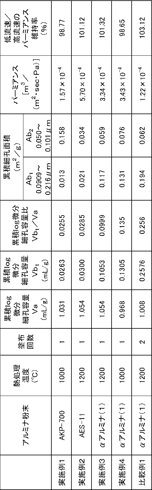
更に、実施例及び比較例について以下の測定も行った。
(5)層aと層bのDLD-maxの測定
なお、水銀圧入法による測定では、スラリーが塗布された後の基材A-12を測定した他、基材A-12のみも測定した。横軸を細孔径とするlog微分細孔容量分布において、基材A-12のみの測定では1つのピークが観測され、スラリーが塗布された基材A-12の測定では2つのピークが観察された。基材A-12のみの測定で観測されたピークにより基材(層a)のDLD-maxを評価し、スラリーが塗布された基材A-12の観測において観察された2つのピークのうち、低細孔径側のピークにより、スラリーにより形成された層(層b)のDLD-maxが評価した。
なお、水銀圧入法による測定では、スラリーが塗布された後の基材A-12を測定した他、基材A-12のみも測定した。横軸を細孔径とするlog微分細孔容量分布において、基材A-12のみの測定では1つのピークが観測され、スラリーが塗布された基材A-12の測定では2つのピークが観察された。基材A-12のみの測定で観測されたピークにより基材(層a)のDLD-maxを評価し、スラリーが塗布された基材A-12の観測において観察された2つのピークのうち、低細孔径側のピークにより、スラリーにより形成された層(層b)のDLD-maxが評価した。
上記(5)に従って測定した結果、アルミナ粉末を含むスラリーにより形成された層(層b)のDLD-maxは、実施例1:0.081μm、実施例2:0.24μm、実施例3:0.16μm、実施例4:0.16μm、比較例1:0.22μmであった。また、層aのDLD-maxは14.7μmであった。
Claims (8)
- 金属酸化物を含む2以上の層が積層された多孔質セラミックス積層体であって、
細孔径が0.51~13.35μmの細孔の累積log微分細孔容量Vaに対する、細孔径が0.0909~0.216μmの細孔の累積log微分細孔容量Vb1の比:Vb1/Vaが0.256未満である多孔質セラミックス積層体。 - 前記Vb1/Vaが0.0255以上である請求項1に記載の多孔質セラミックス積層体。
- 細孔径が0.0909μm~0.216μmの細孔の累積細孔面積Ab1が0.010m2/g以上、0.180m2/g以下である請求項1または2に記載の多孔質セラミックス積層体。
- 細孔径が0.050μm~0.101μmの細孔の累積細孔面積Ab2が0.030m2/g以上、0.160m2/g以下である請求項3記載の多孔質セラミックス積層体。
- 前記Vb1/Vaが0.028超、0.14以下である請求項4に記載の多孔質セラミックス積層体。
- 前記金属酸化物がアルミナを含む請求項1または2に記載の多孔質セラミックス積層体。
- チューブ状またはモノリス状である請求項1または2に記載の多孔質セラミックス積層体。
- 請求項1または2に記載の多孔質セラミックス積層体を含む分離膜。
Applications Claiming Priority (2)
| Application Number | Priority Date | Filing Date | Title |
|---|---|---|---|
| JP2023-002563 | 2023-01-11 | ||
| JP2023002563A JP2024098825A (ja) | 2023-01-11 | 2023-01-11 | 多孔質セラミックス積層体及び分離膜 |
Publications (1)
| Publication Number | Publication Date |
|---|---|
| WO2024150548A1 true WO2024150548A1 (ja) | 2024-07-18 |
Family
ID=91896880
Family Applications (1)
| Application Number | Title | Priority Date | Filing Date |
|---|---|---|---|
| PCT/JP2023/041982 Ceased WO2024150548A1 (ja) | 2023-01-11 | 2023-11-22 | 多孔質セラミックス積層体及び分離膜 |
Country Status (2)
| Country | Link |
|---|---|
| JP (1) | JP2024098825A (ja) |
| WO (1) | WO2024150548A1 (ja) |
Citations (3)
| Publication number | Priority date | Publication date | Assignee | Title |
|---|---|---|---|---|
| US5773103A (en) * | 1995-07-31 | 1998-06-30 | Media And Process Technology Inc. | Inorganic membranes using porous cordierite support |
| JP2013529132A (ja) * | 2010-05-25 | 2013-07-18 | コーニング インコーポレイテッド | コージエライトモノリスにおけるコージエライト膜 |
| WO2020080225A1 (ja) * | 2018-10-15 | 2020-04-23 | 住友化学株式会社 | 多孔質セラミックス積層体及びその製造方法 |
-
2023
- 2023-01-11 JP JP2023002563A patent/JP2024098825A/ja active Pending
- 2023-11-22 WO PCT/JP2023/041982 patent/WO2024150548A1/ja not_active Ceased
Patent Citations (3)
| Publication number | Priority date | Publication date | Assignee | Title |
|---|---|---|---|---|
| US5773103A (en) * | 1995-07-31 | 1998-06-30 | Media And Process Technology Inc. | Inorganic membranes using porous cordierite support |
| JP2013529132A (ja) * | 2010-05-25 | 2013-07-18 | コーニング インコーポレイテッド | コージエライトモノリスにおけるコージエライト膜 |
| WO2020080225A1 (ja) * | 2018-10-15 | 2020-04-23 | 住友化学株式会社 | 多孔質セラミックス積層体及びその製造方法 |
Also Published As
| Publication number | Publication date |
|---|---|
| JP2024098825A (ja) | 2024-07-24 |
Similar Documents
| Publication | Publication Date | Title |
|---|---|---|
| EP2689828B1 (en) | Honeycomb-shaped ceramic separation-membrane structure | |
| EP2832429B1 (en) | Honeycomb shaped porous ceramic body, manufacturing method for same, and honeycomb shaped ceramic separation membrane structure | |
| JP7514183B2 (ja) | 多孔質セラミックス積層体及びその製造方法 | |
| CN103874536B (zh) | 陶瓷过滤器 | |
| EP2594329B1 (en) | Ceramic filter | |
| EP2832430B1 (en) | Honeycomb shaped porous ceramic body, manufacturing method for same, and honeycomb shaped ceramic separation membrane structure | |
| JP4607634B2 (ja) | セラミックフィルタ | |
| CN115073202A (zh) | 一种基于粘结剂喷射的梯度孔结构陶瓷膜及其制备方法和应用 | |
| WO2024150547A1 (ja) | 多孔質セラミックス体及び分離膜 | |
| JP2024098825A (ja) | 多孔質セラミックス積層体及び分離膜 | |
| WO2021215205A1 (ja) | 多孔質セラミックス積層体及びその製造方法 | |
| CN101316648B (zh) | 用于气体分离的功能化无机膜 | |
| EP3778002A1 (en) | Base material for membrane filter and method for producing same | |
| RU2579713C2 (ru) | Способ изготовления фильтрующего материала | |
| WO2025028550A1 (ja) | 多孔質セラミックス積層体及び分離膜 | |
| WO2025053016A1 (ja) | 多孔質セラミックス積層体及び分離膜 | |
| WO2025053017A1 (ja) | 多孔質セラミックス積層体及び分離膜 | |
| JP2025037436A (ja) | 多孔質セラミックス積層体及び分離膜 | |
| JP2025022448A (ja) | セラミックス多孔質積層体の製造方法 | |
| Kagramanov et al. | Ceramic membranes with selective layers based on SiO2, TiO2, and ZrO2 | |
| WO2024185441A1 (ja) | 多孔質セラミックス層、多孔質セラミックス積層体及び分離膜 | |
| WO2024185442A1 (ja) | 多孔質セラミックス層、多孔質セラミックス積層体及び分離膜 | |
| JP2005177693A (ja) | フィルタ及びその製造方法 | |
| WO2017061382A1 (ja) | ハニカムフィルタ |
Legal Events
| Date | Code | Title | Description |
|---|---|---|---|
| 121 | Ep: the epo has been informed by wipo that ep was designated in this application |
Ref document number: 23916165 Country of ref document: EP Kind code of ref document: A1 |
|
| NENP | Non-entry into the national phase |
Ref country code: DE |
|
| 122 | Ep: pct application non-entry in european phase |
Ref document number: 23916165 Country of ref document: EP Kind code of ref document: A1 |