WO2024150407A1 - 空調システム及び空調システムの制御方法 - Google Patents
空調システム及び空調システムの制御方法 Download PDFInfo
- Publication number
- WO2024150407A1 WO2024150407A1 PCT/JP2023/000776 JP2023000776W WO2024150407A1 WO 2024150407 A1 WO2024150407 A1 WO 2024150407A1 JP 2023000776 W JP2023000776 W JP 2023000776W WO 2024150407 A1 WO2024150407 A1 WO 2024150407A1
- Authority
- WO
- WIPO (PCT)
- Prior art keywords
- air conditioning
- conditioning system
- air
- controller
- terminal device
- Prior art date
- Legal status (The legal status is an assumption and is not a legal conclusion. Google has not performed a legal analysis and makes no representation as to the accuracy of the status listed.)
- Ceased
Links
Images



Classifications
-
- F—MECHANICAL ENGINEERING; LIGHTING; HEATING; WEAPONS; BLASTING
- F24—HEATING; RANGES; VENTILATING
- F24F—AIR-CONDITIONING; AIR-HUMIDIFICATION; VENTILATION; USE OF AIR CURRENTS FOR SCREENING
- F24F11/00—Control or safety arrangements
- F24F11/50—Control or safety arrangements characterised by user interfaces or communication
- F24F11/56—Remote control
-
- F—MECHANICAL ENGINEERING; LIGHTING; HEATING; WEAPONS; BLASTING
- F24—HEATING; RANGES; VENTILATING
- F24F—AIR-CONDITIONING; AIR-HUMIDIFICATION; VENTILATION; USE OF AIR CURRENTS FOR SCREENING
- F24F11/00—Control or safety arrangements
- F24F11/30—Control or safety arrangements for purposes related to the operation of the system, e.g. for safety or monitoring
-
- F—MECHANICAL ENGINEERING; LIGHTING; HEATING; WEAPONS; BLASTING
- F24—HEATING; RANGES; VENTILATING
- F24F—AIR-CONDITIONING; AIR-HUMIDIFICATION; VENTILATION; USE OF AIR CURRENTS FOR SCREENING
- F24F11/00—Control or safety arrangements
- F24F11/50—Control or safety arrangements characterised by user interfaces or communication
- F24F11/56—Remote control
- F24F11/58—Remote control using Internet communication
-
- F—MECHANICAL ENGINEERING; LIGHTING; HEATING; WEAPONS; BLASTING
- F24—HEATING; RANGES; VENTILATING
- F24F—AIR-CONDITIONING; AIR-HUMIDIFICATION; VENTILATION; USE OF AIR CURRENTS FOR SCREENING
- F24F11/00—Control or safety arrangements
- F24F11/62—Control or safety arrangements characterised by the type of control or by internal processing, e.g. using fuzzy logic, adaptive control or estimation of values
-
- F—MECHANICAL ENGINEERING; LIGHTING; HEATING; WEAPONS; BLASTING
- F24—HEATING; RANGES; VENTILATING
- F24F—AIR-CONDITIONING; AIR-HUMIDIFICATION; VENTILATION; USE OF AIR CURRENTS FOR SCREENING
- F24F11/00—Control or safety arrangements
- F24F11/50—Control or safety arrangements characterised by user interfaces or communication
- F24F11/52—Indication arrangements, e.g. displays
Definitions
- This disclosure relates to an air conditioning system equipped with an air conditioner operated by a terminal device and a method for controlling the air conditioning system.
- Patent Document 1 discloses such an air conditioning system in which the air conditioning unit closest to the user is the operation target and controlled via a management device.
- the air conditioning system of Patent Document 1 estimates the distance between the multiple air conditioning units and the terminal device based on the strength of electromagnetic waves received by the terminal device from multiple electromagnetic wave emitters arranged on the ceiling corresponding to the multiple air conditioning units.
- the present disclosure has been made to solve the problems described above, and aims to provide an air conditioning system and a method for controlling an air conditioning system that allows a user to easily operate the air conditioning device of their choice.
- the air conditioning system comprises a plurality of air conditioning devices that condition a target space, a plurality of remote controllers each linked to the plurality of air conditioning devices, and a plurality of identification means each linked to the plurality of remote controllers, and a target controller, which is one of the plurality of remote controllers identified using the identification means, controls the air conditioning device linked to the target controller based on an operation signal input from a terminal device.
- the method of controlling an air conditioning system is a method of controlling an air conditioning system that includes a plurality of air conditioning devices that condition a space to be air-conditioned, a plurality of remote controllers each linked to the plurality of air conditioning devices, and a plurality of identification means each linked to the plurality of remote controllers, and includes a step of identifying one of the plurality of remote controllers as a target controller using the identification means, and a step of controlling the air conditioning device linked to the target controller based on an operation signal input from a terminal device via the target controller.
- the air conditioning system has a plurality of identification means each associated with a plurality of remote controllers, and the target controller is identified using the identification means. Therefore, in the air conditioning system, the user can easily operate the air conditioner of his/her choice.
- FIG. 1 is a schematic configuration diagram showing an air conditioning system according to a first embodiment.
- 1 is a functional block diagram showing an air conditioning system according to a first embodiment.
- 3 is a diagram for explaining a connection method between a terminal device and a remote controller according to the first embodiment.
- FIG. 2 is a hardware configuration diagram showing a control device of a terminal device according to the first embodiment.
- FIG. 4 is a flowchart showing a control method for the air conditioning system according to the first embodiment.
- FIG. 1 is a schematic diagram showing the air conditioning system 100 according to the first embodiment.
- the air conditioning system 100 has air conditioners 1a to 1d, remote controllers 2a to 2d, environmental sensors 3a to 3d, and a terminal device 4.
- Each device of the air conditioning system 100 is provided in, for example, the same room.
- four air conditioners 1a to 1d, remote controllers 2a to 2d, and environmental sensors 3a to 3d are illustrated as an example, but the number of these may be two, three, or five or more. In addition, these do not have to be provided in the same room.
- FIG. 1 only the indoor units of the air conditioners 1a to 1d are shown, and the outdoor units are omitted.
- Air conditioning unit 1a is a device that conditions the air of the conditioned space Sa in which air conditioning unit 1a is installed, among the indoor spaces of a room.
- the configuration, arrangement, and functions of air conditioning units 1b, 1c, and 1d are also similar to air conditioning unit 1a.
- air conditioning units 1b to 1d are devices that condition the air of the conditioned spaces Sb to Sd in which air conditioning units 1b to 1d are installed, among the indoor spaces of a room.
- air conditioning unit 1 when there is no need to distinguish between air conditioning units 1a to 1d, they will simply be referred to as air conditioning unit 1.
- the remote controller 2a is connected by wire to a corresponding air conditioning device 1a among the multiple air conditioning devices 1, and controls the air conditioning device 1a.
- the wiring connecting the remote controller 2a to the air conditioning device 1a is hidden, for example, behind a wall, and the user cannot visually confirm the connection between the remote controller 2a and the air conditioning device 1a.
- the user can operate the remote controller 2a to check a unique ID and the like for identifying the remote controller 2a from the other remote controllers 2b to 2d.
- the configuration, arrangement, and functions of the remote controllers 2b to 2d are similar to those of the remote controller 2a. That is, the remote controllers 2b to 2d are connected by wire to the corresponding air conditioning units 1b to 1d among the multiple air conditioning units 1, and control the air conditioning units 1b to 1d.
- the remote controller 2 when there is no need to distinguish between the remote controllers 2a to 2d, they will be simply referred to as the remote controller 2.
- the multiple remote controllers 2 may be provided in locations unrelated to the corresponding air-conditioned spaces, for example by being arranged together on a wall in a room.
- the remote controllers 2 and the air conditioning units 1 may also be connected wirelessly.
- the environmental sensor 3a measures the environmental state of the air-conditioned space Sa in which the environmental sensor 3a is installed.
- the environmental state is, for example, the temperature, humidity, CO2 concentration, or PM2.5 concentration in the air-conditioned space Sa.
- the environmental sensor 3a also wirelessly communicates with a corresponding remote controller 2a among the multiple remote controllers 2 to transmit information indicating the measured environmental state to the remote controller 2a.
- the communication between the environmental sensor 3a and the remote controller 2a is performed by a wireless LAN such as Wi-Fi (registered trademark; omitted below), or Bluetooth (registered trademark; omitted below), etc.
- the environmental sensor 3a is installed in the air-conditioned space Sa so that its position can be changed.
- the environmental sensor 3a is installed in the air-conditioned space Sa except for the ceiling space in the room.
- the environmental sensor 3a is, for example, a free-standing or wall-mounted type, and is portable, so that the user can easily change the installation position.
- the environmental sensor 3a is placed closer to the corresponding air conditioner 1a than the other environmental sensors 3b to 3d.
- the configuration, arrangement, and functions of the environmental sensors 3b to 3d are the same as those of the environmental sensor 3a.
- the environmental sensors 3b to 3d are installed under the same conditions as the environmental sensor 3a, and measure the environmental conditions of the air-conditioned spaces Sb to Sd in which they are installed.
- the environmental sensor 3 corresponds to the "identification means" of this disclosure.
- the terminal device 4 is, for example, a device owned by the user U, such as a smartphone, tablet, or PC terminal.
- An application for operating the air conditioning device 1 is installed on the terminal device 4.
- the application for operating the air conditioning device 1 will be referred to as an air conditioning app.
- the air conditioning app enables the terminal device 4 to realize a function for controlling the air conditioning device 1 linked to the remote controller 2 via the remote controller 2.
- the terminal device 4 wirelessly communicates with the remote controller 2 and the environmental sensor 3, for example, via a wireless LAN such as Wi-Fi or a communication standard such as Bluetooth.
- the air conditioning system 100 identifies the destination controller associated with the air conditioning apparatus 1 that the user wishes to operate, without going through any settings by the user.
- the destination controller is the remote controller 2 associated with the air conditioning apparatus 1 closest to the user. The user can operate the air conditioning apparatus 1 closest to the user via the destination controller.
- the air conditioning system 100 may also have a system controller that provides integrated control of the air conditioning device 1.
- FIG. 2 is a functional block diagram showing the air conditioning system 100 according to the first embodiment.
- the remote controller 2 has an operation and display device 21, a control device 22, and a communication device 23.
- the operation and display device 21 is made up of a display unit (not shown) and an operation unit (not shown).
- the display unit is, for example, an LCD screen, and displays the operation details of the air conditioning device 1 linked to the remote controller 2.
- the operation details include whether the air conditioning device 1 is operating, the operation mode, the set temperature, the indoor temperature, the air direction, and the air volume.
- the operation unit is, for example, a physical button, and can input the operation details for the air conditioning device 1 linked to the remote controller 2.
- the operation details include starting and stopping the operation of the air conditioning device 1, and changing the operation mode, the set temperature, the air direction, and the air volume.
- the control device 22 generates an operation signal indicating the operation content input from the operation display device 21, and instructs the communication device 23 to send this operation signal to the air conditioning device 1.
- the control device 22 also generates a first advertisement signal, and instructs the communication device 23 to transmit the first advertisement signal to the terminal device 4.
- the first advertisement signal includes identification information indicating the remote controller 2 that transmits the information, and identification information of the environmental sensor 3 linked to the remote controller 2 that transmits the information.
- the identification information is information unique to the remote controller 2 and the environmental sensor 3, and is, for example, the BD address or unique ID of the device.
- the communication device 23 transmits an operation signal to the corresponding air conditioning device 1 in response to an instruction from the control device 22. Similarly, when the communication device 23 receives an operation signal from the terminal device 4, it transmits this to the corresponding air conditioning device 1. Furthermore, when the communication device 23 receives environmental information (described below) from the environmental sensor 3, it transmits this to the corresponding air conditioning device 1. The communication device 23 also transmits a first advertising signal to the terminal device 4. The first advertising signal is transmitted periodically. Furthermore, the communication devices 23 of all remote controllers 2 transmit the first advertising signal with equal strength.
- the environmental sensor 3 has an environmental measuring device 31, a control device 32, and a communication device 33.
- the environmental measuring device 31 measures the environmental state in the space to be air-conditioned.
- the control device 32 generates environmental information indicating the measured environmental state, and instructs the communication device 33 to transmit this environmental information to the remote controller 2.
- the control device 32 also generates a second advertising signal, and instructs the communication device 33 to transmit the second advertising signal to the terminal device 4.
- the second advertising signal includes identification information of the environmental sensor 3 transmitting the information.
- the communication device 33 transmits environmental information to the corresponding remote controller 2 in response to an instruction from the control device 32.
- the communication device 33 transmits a second advertising signal to the terminal device 4.
- the second advertising signal is transmitted periodically.
- the communication devices 33 of all the environmental sensors 3 transmit the second advertising signal with the same strength.
- the terminal device 4 has an operation display device 41, a control device 42, and a communication device 43.
- the operation display device 41 is, for example, a touch panel.
- the control device 42 causes the operation display device 41 to display an operation screen for operating the air conditioning device 1.
- the control device 42 also controls the content displayed on the operation screen based on the operation content input from the operation screen.
- the control device 42 then generates an operation signal indicating the operation content input from the operation screen, and instructs the communication device 43 to transmit the operation signal to the remote controller 2 identified as the target controller.
- the control device 42 determines the target controller based on the first advertising signal and the second advertising signal.
- a specific connection method between the terminal device 4 and the remote controller 2 will be described with reference to FIG. 3.
- FIG. 3 is a diagram for explaining the connection method between the terminal device 4 and the remote controller 2 according to the first embodiment.
- the control device 42 determines the environmental sensor 3 indicated by the second advertising signal received with the highest strength among the second advertising signals received by the communication device 43 as the target sensor linked to the target controller, and stores the identification information of this target sensor. This utilizes the principle that the strength of radio waves decreases the farther the distance from the source of transmission.
- the communication devices 33 of all environmental sensors 3 transmit second advertising signals with the same strength, so that it can be determined that the higher the strength of the received radio waves, the closer the radio waves are to the terminal device 4.
- the strength of the received radio wave is, for example, RSSI (Received Signal Strength Indicator) [dBm].
- RSSI Receiveived Signal Strength Indicator
- the purpose sensor corresponds to the "purpose identification means" of this disclosure.
- the control device 42 searches for a first advertising signal including identification information of the target sensor among the first advertising signals received by the communication device 43. When a first advertising signal including the target identification information is found, it determines that the remote controller 2 indicated by this first advertising signal is the target controller, and stores the identification information indicating this remote controller 2. As described above, since the environmental sensor 3 corresponds to the air conditioning device 1 and is provided near the environmental sensor 3, the target controller identified by the above means is the device linked to the air conditioning device 1 that is closest to the user. The terminal device 4 then establishes communication with the target controller based on the identification information indicating the target controller, and transmits an operation signal to the air conditioning device 1 via the target controller.
- the terminal device 4 first receives the second advertising signal with the highest strength from the environmental sensor 3c among the multiple environmental sensors 3.
- the size of the arrow corresponds to the radio wave strength when the terminal device 4 receives the signal.
- the second advertising signal from the environmental sensor 3 contains the identification information of the environmental sensor 3c, "AA:BB:CC”. Therefore, the terminal device 4 next searches for a first advertising signal that contains the information "AA:BB:CC" as the identification information of the environmental sensor 3c among the first advertising signals transmitted from the multiple remote controllers 2. At this time, the terminal device 4 finds that the first advertising signal transmitted from the remote controller 2c linked to the environmental sensor 3c contains the information "AA:BB:CC" as the identification information of the environmental sensor 3c.
- the terminal device 4 then stores the identification information "XX:YY:ZZ" transmitted by the remote controller 2c as the identification information of the target controller, connects to the remote controller 2c based on this identification information, and transmits an operation signal to the air conditioning device 1c via the remote controller 2c.
- the air conditioning device 1 When the air conditioning device 1 receives an operation signal from the remote controller 2, it performs an operation based on the operation content indicated by the received operation signal and the environmental state indicated by the environmental information.
- FIG. 4 is a hardware configuration diagram showing the control device 42 of the terminal device 4 according to the first embodiment.
- the control device 42 has a processor 101 such as a CPU and a memory 102. Each function of the control device 42 is realized by the processor 101 and the memory 102.
- FIG. 4 shows that the processor 101 and the memory 102 are connected to each other so as to be able to communicate with each other via a bus 103.
- the air conditioning app is written as a program and stored in memory 102.
- the processor 101 realizes the functions of the control device 42 by reading and executing the air conditioning app stored in memory 102.
- the control device 22 of the remote controller 2 and the control device 32 of the environmental sensor 3 also consist of a processor and memory, similar to the control device 42 of the terminal device 4.
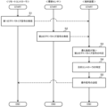
- FIG. 5 is a flowchart showing a method for controlling the air conditioning system 100 according to the first embodiment.
- the communication device 23 of the remote controller 2 transmits a first advertising signal (step S1)
- the communication device 33 of the environmental sensor 3 transmits a second advertising signal (step S2).
- the first advertising signal and the second advertising signal are each transmitted periodically, and may be transmitted simultaneously, or the second advertising signal may be transmitted first.
- the control device 42 of the terminal device 4 determines which second advertising signal has the highest intensity (step S3). Next, the control device 42 of the terminal device 4 identifies the remote controller 2 linked to the environmental sensor 3 that emitted the second advertising signal with the highest intensity as the target controller (step S4). Then, the control device 42 of the terminal device 4 transmits an operation signal to the target controller (step S5).
- the air conditioning system 100 of the first embodiment has a plurality of identification means each associated with a plurality of remote controllers 2, and the target controller is identified using the identification means. Therefore, in the air conditioning system 100, the user can easily operate the air conditioning device 1 that he or she desires.
- the environmental sensor 3 of the air conditioning system 100 of embodiment 1 is installed in a position that can be changed in the space to be air conditioned. Therefore, even if the user wants to retrofit the environmental sensor 3 so that it can be operated by the terminal device 4 when only the air conditioning unit 1 is already installed, the installation of the terminal device 4 can be easily performed without the need for construction work. Therefore, the air conditioning system 100 of embodiment 1 can be easily constructed by the user.
- the air conditioning system 100 of the first embodiment can be constructed by adding only a relatively inexpensive remote controller 2 and an environmental sensor 3 to an existing air conditioning device 1, thereby reducing costs and construction labor.
- conventional terminal devices that do not communicate with the environmental sensor 3 are unable to identify the air conditioning device 1 located in the closest position.
- the remote controllers 2 may be placed regardless of the location of the air conditioning device 1, and the terminal device is therefore unable to identify the remote controller 2 linked to the air conditioning device 1 located in the closest position.
- the user had to search for the remote controller 2 to operate the air conditioning device 1 closest to him/her, and then check the identification information of this remote controller 2.
- the user had to operate the operation display device 21 of the remote controller 2, which was time-consuming for the user.
- the air conditioning system 100 of the first embodiment uses an environmental sensor 3 provided in correspondence with the air conditioning unit 1 to have the terminal device 4 automatically recognize the identification information of the remote controller 2 for operating the air conditioning unit 1 closest to the user. Therefore, the user can operate the air conditioning unit 1 closest to him or her on the spot. For example, even if an office employs a free address system in which the seat where work is done varies from day to day, and the air conditioning unit 1 that the user wants to use also varies from day to day, the user does not need to search for the remote controller 2 or check its identification information each time. In this way, the air conditioning system 100 of the first embodiment improves the convenience of using the air conditioning unit 1.
- the air conditioning device 1 is controlled based on the environmental state measured by the environmental sensor 3.
- the environmental sensor 3 is arranged in the air-conditioned space, it is possible to measure the environmental state according to the environment in which the user is spending time by comparing it with a sensor provided inside the air conditioning device 1 or inside the remote controller 2.
- the air conditioning device 1 is controlled based on the temperature measured by the environmental sensor 3. Therefore, in such a case, the air conditioning device 1 in the air-conditioned space where the user is spending time can lower the temperature of the air blown out and increase the air volume compared to other air conditioning devices 1. In this way, the air conditioning system 100 of the first embodiment can improve the accuracy of air conditioning and further improve the comfort for the user.
- the target controller is identified by the environmental sensor 3. Since the installation position of the environmental sensor 3 can be changed, if the environmental sensor 3 is installed at a lower position than the air conditioning device 1 installed at a high position on the ceiling or wall, the distance to the terminal device 4 will be closer. Therefore, the distance for each environmental sensor 3 can be estimated with higher accuracy.
- the environmental sensor 3 may be placed anywhere in the space to be air-conditioned, so long as it is placed closer to the corresponding air conditioning device 1 than other environmental sensors 3. For example, placing the environmental sensor 3 closer to the user can improve comfort for the user, as already explained. Also, placing the environmental sensor 3 closer to the air conditioning device 1, such as by attaching it directly to the air conditioning device 1, can reduce the possibility of operating an air conditioning device 1 other than the one the user wants to operate.
- the present disclosure is not limited to the configuration of the above embodiments, and various modifications or combinations are possible within the scope of the technical concept.
- other small digital devices with wireless communication capabilities may be provided in place of the environmental sensor 3.
- a beacon or the like that has only wireless communication capabilities may be used.
- the terminal device 4 can be automatically made to recognize the identification information of the remote controller 2 for operating the air conditioning device 1 closest to the user.
- a sticker or the like on which a two-dimensional code is printed may be used.
- the two-dimensional code is, for example, a QR code (registered trademark) and indicates the identification information of the remote controller 2. Therefore, the medium on which the two-dimensional code is printed also corresponds to the "identification means" of this disclosure.
- the sticker on which the two-dimensional code is printed is provided in the space to be air-conditioned, and the installation position can be changed. Specifically, for example, it is affixed to the main body of the air conditioning device 1 linked to the remote controller 2 or to a desk or the like close to the air conditioning device 1.
- the two-dimensional code is read by the terminal device 4 using the camera function of the terminal device 4.
- the terminal device 4 can obtain the identification information indicated by the two-dimensional code and control the air conditioning device 1 as the target controller via the remote controller 2 indicated by the obtained identification information.
- the environmental sensor 3 can be omitted.
- the procedure by which the terminal device 4 identifies the target controller is not limited to the above-mentioned form.
- the terminal device 4 may identify the target controller as follows. First, the environmental sensor 3 is caused to acquire identification information of the corresponding remote controller 2. This process may be performed when the environmental sensor 3 is installed. Then, the second advertising signal is made to include identification information indicating the environmental sensor 3 that transmits the information, and identification information of the remote controller 2 linked to the environmental sensor 3 that transmits the information, and the information is transmitted from the environmental sensor 3 to the terminal device 4. In this case as well, the terminal device 4 can identify the target controller based on the identification information of the remote controller 2 indicated by the second advertising signal received with the highest strength among the second advertising signals received from the environmental sensor 3.
- the terminal device 4 may be allowed to operate the air conditioning device 1 only when the radio wave strength exceeds a threshold.
- the threshold is, for example, the minimum strength that can be obtained when the terminal device 4 is present in a room.
- the air conditioning system 100 can restrict operation of the air conditioning device 1 by third parties who should not operate the air conditioning device 1, improving security.
- the terminal device 4 may receive not only the identification state but also the environmental state measured by the environmental sensor 3. At this time, for example, the measured temperature, humidity, CO2 concentration, or PM2.5 concentration may be displayed on the operation screen of the terminal device 4. In this case, the user can refer to the displayed information when operating the air conditioning device 1.
- the terminal device 4 may display an option on the operation screen of the terminal device 4 for selecting which air conditioning device 1 to operate.
- the terminal device 4 may also be configured to operate multiple air conditioning devices 1.
Landscapes
- Engineering & Computer Science (AREA)
- Chemical & Material Sciences (AREA)
- Combustion & Propulsion (AREA)
- Mechanical Engineering (AREA)
- General Engineering & Computer Science (AREA)
- Human Computer Interaction (AREA)
- Physics & Mathematics (AREA)
- Fuzzy Systems (AREA)
- Mathematical Physics (AREA)
- Signal Processing (AREA)
- Air Conditioning Control Device (AREA)
Priority Applications (3)
| Application Number | Priority Date | Filing Date | Title |
|---|---|---|---|
| DE112023005559.9T DE112023005559T5 (de) | 2023-01-13 | 2023-01-13 | Klimatisierungssystem und verfahren zum steuern eines klimatisierungssystems |
| JP2024569975A JP7843865B2 (ja) | 2023-01-13 | 2023-01-13 | 空調システム及び空調システムの制御方法 |
| PCT/JP2023/000776 WO2024150407A1 (ja) | 2023-01-13 | 2023-01-13 | 空調システム及び空調システムの制御方法 |
Applications Claiming Priority (1)
| Application Number | Priority Date | Filing Date | Title |
|---|---|---|---|
| PCT/JP2023/000776 WO2024150407A1 (ja) | 2023-01-13 | 2023-01-13 | 空調システム及び空調システムの制御方法 |
Publications (1)
| Publication Number | Publication Date |
|---|---|
| WO2024150407A1 true WO2024150407A1 (ja) | 2024-07-18 |
Family
ID=91896692
Family Applications (1)
| Application Number | Title | Priority Date | Filing Date |
|---|---|---|---|
| PCT/JP2023/000776 Ceased WO2024150407A1 (ja) | 2023-01-13 | 2023-01-13 | 空調システム及び空調システムの制御方法 |
Country Status (3)
| Country | Link |
|---|---|
| JP (1) | JP7843865B2 (https=) |
| DE (1) | DE112023005559T5 (https=) |
| WO (1) | WO2024150407A1 (https=) |
Citations (3)
| Publication number | Priority date | Publication date | Assignee | Title |
|---|---|---|---|---|
| WO2015111178A1 (ja) * | 2014-01-24 | 2015-07-30 | 日立アプライアンス株式会社 | 空気調和機操作システム |
| WO2018127993A1 (ja) * | 2017-01-05 | 2018-07-12 | 三菱電機株式会社 | 無線通信システム |
| WO2019229800A1 (ja) * | 2018-05-28 | 2019-12-05 | 三菱電機株式会社 | センサ連携設備システム |
-
2023
- 2023-01-13 DE DE112023005559.9T patent/DE112023005559T5/de active Pending
- 2023-01-13 WO PCT/JP2023/000776 patent/WO2024150407A1/ja not_active Ceased
- 2023-01-13 JP JP2024569975A patent/JP7843865B2/ja active Active
Patent Citations (3)
| Publication number | Priority date | Publication date | Assignee | Title |
|---|---|---|---|---|
| WO2015111178A1 (ja) * | 2014-01-24 | 2015-07-30 | 日立アプライアンス株式会社 | 空気調和機操作システム |
| WO2018127993A1 (ja) * | 2017-01-05 | 2018-07-12 | 三菱電機株式会社 | 無線通信システム |
| WO2019229800A1 (ja) * | 2018-05-28 | 2019-12-05 | 三菱電機株式会社 | センサ連携設備システム |
Also Published As
| Publication number | Publication date |
|---|---|
| DE112023005559T5 (de) | 2025-10-30 |
| JP7843865B2 (ja) | 2026-04-10 |
| JPWO2024150407A1 (https=) | 2024-07-18 |
Similar Documents
| Publication | Publication Date | Title |
|---|---|---|
| JP4989702B2 (ja) | 設備制御端末、設備制御システム、設備制御方法並びにプログラム | |
| WO2012101762A1 (ja) | 制御装置、制御方法及びプログラム | |
| US20220178570A1 (en) | Air conditioning system, and an information providing method using air conditioning system | |
| JP6470918B2 (ja) | 空気調和システム | |
| US11703245B2 (en) | Ventilation system | |
| US12038186B2 (en) | Air-conditioning system with signal intensity adjustment | |
| CN109405193B (zh) | 空调系统及其遥控器配对方法 | |
| KR101367126B1 (ko) | 시스템 에어컨과 리모컨의 바인딩장치 그 방법 | |
| WO2020066017A1 (ja) | 空気調和システムおよびアプリケーションプログラム | |
| JP7843865B2 (ja) | 空調システム及び空調システムの制御方法 | |
| WO2017208344A1 (ja) | 空調システム | |
| JP2007078270A (ja) | 空調システム | |
| WO2017081721A1 (ja) | 空調制御システム | |
| US12031740B2 (en) | Facility device management system | |
| KR100791928B1 (ko) | 시스템 에어컨의 통신에러 진단방법 | |
| KR102450686B1 (ko) | 복수의 단말들간의 무선 연결 자동 전환 시스템 및 방법 | |
| US12584649B2 (en) | Air conditioner system and control method | |
| WO2023219062A1 (ja) | 冷媒検知装置、及び空調システム | |
| JP7621550B2 (ja) | 空調制御システム、無線端末、空調制御方法及びプログラム | |
| JP2020198498A (ja) | 遠隔制御システム | |
| JP2020051668A (ja) | 空気調和装置、情報処理装置及びプログラム | |
| JP2023086385A (ja) | 空気調和システム | |
| JP2022134276A (ja) | 環境制御システム、環境制御装置、および環境制御方法 | |
| JP2012021661A (ja) | 存在位置検出システム | |
| JP2006228034A (ja) | 計測管理システム |
Legal Events
| Date | Code | Title | Description |
|---|---|---|---|
| 121 | Ep: the epo has been informed by wipo that ep was designated in this application |
Ref document number: 23916028 Country of ref document: EP Kind code of ref document: A1 |
|
| WWE | Wipo information: entry into national phase |
Ref document number: 2024569975 Country of ref document: JP |
|
| WWE | Wipo information: entry into national phase |
Ref document number: 112023005559 Country of ref document: DE |
|
| WWP | Wipo information: published in national office |
Ref document number: 112023005559 Country of ref document: DE |
|
| 122 | Ep: pct application non-entry in european phase |
Ref document number: 23916028 Country of ref document: EP Kind code of ref document: A1 |