WO2024150281A1 - 状態検知システム、検知装置、状態検知方法及び状態検知プログラム - Google Patents
状態検知システム、検知装置、状態検知方法及び状態検知プログラム Download PDFInfo
- Publication number
- WO2024150281A1 WO2024150281A1 PCT/JP2023/000340 JP2023000340W WO2024150281A1 WO 2024150281 A1 WO2024150281 A1 WO 2024150281A1 JP 2023000340 W JP2023000340 W JP 2023000340W WO 2024150281 A1 WO2024150281 A1 WO 2024150281A1
- Authority
- WO
- WIPO (PCT)
- Prior art keywords
- correlation
- signal
- unit
- time correlation
- propagation path
- Prior art date
- Legal status (The legal status is an assumption and is not a legal conclusion. Google has not performed a legal analysis and makes no representation as to the accuracy of the status listed.)
- Ceased
Links
Images



Classifications
-
- G—PHYSICS
- G01—MEASURING; TESTING
- G01P—MEASURING LINEAR OR ANGULAR SPEED, ACCELERATION, DECELERATION, OR SHOCK; INDICATING PRESENCE, ABSENCE, OR DIRECTION, OF MOVEMENT
- G01P13/00—Indicating or recording presence, absence, or direction, of movement
Definitions
- the present invention relates to a condition detection system, a detection device, a condition detection method, and a condition detection program.
- CSI Channel state information
- Non-Patent Document 1 discloses an object detection system that uses wireless LAN propagation channel information to detect the direction of movement of an object even in an environment where there are many changes in the wireless propagation environment other than the detection target and there is little multipath.
- the present invention has been made in consideration of the above-mentioned problems, and aims to provide a condition detection system, detection device, condition detection method, and condition detection program that can accurately detect the condition of an object without prior learning.
- a condition detection system is a condition detection system including a transmitting device that transmits a predetermined signal, and a detecting device that detects the condition of an object on the propagation path of the signal transmitted by the transmitting device.
- the detecting device is characterized by having a receiving unit that receives, via the propagation path, a wireless frame that includes a known signal sequence and is repeatedly transmitted by the transmitting device, an extracting unit that extracts a corresponding signal that corresponds to the known signal sequence from the wireless frame received by the receiving unit, a correlation signal calculating unit that calculates a correlation signal that indicates the correlation between the corresponding signal extracted by the extracting unit and the known signal sequence, a time correlation calculating unit that calculates the time correlation of the correlation signal calculated by the correlation signal calculating unit, and a determining unit that determines that the object is in a stationary state when the time correlation calculated by the time correlation calculating unit is equal to or greater than a predetermined threshold value.
- the detection device is characterized by having a receiving unit that receives a wireless frame, some of which includes a known signal sequence, repeatedly transmitted by a transmitting device via a propagation path of the wireless frame transmitted by the transmitting device, an extracting unit that extracts a corresponding signal corresponding to the known signal sequence from the wireless frame received by the receiving unit, a correlation signal calculating unit that calculates a correlation signal indicating a correlation between the corresponding signal extracted by the extracting unit and the known signal sequence, a time correlation calculating unit that calculates a time correlation of the correlation signal calculated by the correlation signal calculating unit, and a determining unit that determines that an object on the propagation path is stationary when the time correlation calculated by the time correlation calculating unit is equal to or greater than a predetermined threshold value.
- a state detection method for detecting the state of an object on a propagation path of a signal transmitted by a transmitting device that transmits a predetermined signal, the state detection method including a receiving step of receiving, via the propagation path, a wireless frame that includes a known signal sequence in part and is repeatedly transmitted by the transmitting device, an extraction step of extracting a corresponding signal corresponding to the known signal sequence from the wireless frame received by the receiving step, a correlation signal calculation step of calculating a correlation signal that indicates a correlation between the corresponding signal extracted by the extraction step and the known signal sequence, a time correlation calculation step of calculating a time correlation of the correlation signal calculated by the correlation signal calculation step, and a determination step of determining that the object is in a stationary state when the time correlation calculated by the time correlation calculation step is equal to or greater than a predetermined threshold value.
- the state of an object can be detected with high accuracy even without prior learning.
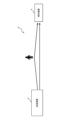
- FIG. 1 is a diagram showing an overview of a condition detection system according to an embodiment
- FIG. 2 is a functional block diagram illustrating functions of a detection device according to an embodiment.
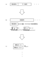
- 1A is a diagram illustrating a radio frame including a known signal sequence in a part of the radio frame repeatedly transmitted by a transmitting device
- FIG. 1B is a diagram illustrating a correlation signal calculated by a correlation signal calculation unit
- FIG. 1C is a diagram illustrating a time correlation calculated by a time correlation calculation unit.
- FIG. 2 is a diagram illustrating an example of a hardware configuration of a detection device according to an embodiment.
- 1A is a diagram showing a schematic diagram of a state detection system detecting a person in a house in a state of motion
- FIG. 1B is a diagram showing a schematic diagram of a state detection system detecting a person in a house in a state of motion
- FIG. 1 is a diagram showing an overview of a condition detection system 1 according to one embodiment.
- a condition detection system 1 includes, for example, a transmitting device 2 that transmits a predetermined signal, and a detecting device 3 that detects the condition of an object on the propagation path of the signal transmitted by the transmitting device 2.
- the transmitting device 2 is a communication device used for, for example, local 5G, Wi-Fi (registered trademark), Bluetooth (registered trademark), and other wireless systems, and the system type and frequency may be any type.
- the detection device 3 has a function of receiving radio waves transmitted by the transmission device 2, and may be, for example, a software radio device having a function of observing the waveform of the received radio waves and a function of analyzing the observed waveform.
- the objects whose states are detected by the state detection system 1 include people and the like.
- the state detection system 1 is also configured to be able to detect whether a person is in a moving state (motion state) or a stationary state (stationary state).
- FIG. 2 is a functional block diagram illustrating the functions possessed by the detection device 3 according to one embodiment.
- the detection device 3 has, for example, a receiving unit 30, an extracting unit 31, a correlation signal calculating unit 32, a time correlation calculating unit 33, a determining unit 34, a learning unit 35, a distinguishing unit 36, and an output unit 37.
- the receiving unit 30 receives the wireless frame, which includes a known signal sequence in part and is repeatedly transmitted by the transmitting device 2, via the propagation path of the signal transmitted by the transmitting device 2, and outputs it to the extracting unit 31.
- the length of the known signal sequence is set to be longer than the maximum delay wavelength in the propagation path of the signal transmitted by the transmitting device 2.
- the signal sequence of the signal transmitted by the transmitting device 2 may be unknown as long as the repetition period is known.
- the extraction unit 31 extracts a corresponding signal corresponding to the known signal sequence of the signal transmitted by the transmission device 2 from the wireless frame received by the reception unit 30, and outputs it to the correlation signal calculation unit 32. For example, the extraction unit 31 sequentially slides the known signal sequence for the received signal (the signal transmitted by the transmission device 2) to extract a corresponding signal corresponding to the known signal sequence. More specifically, since peaks occur in the radio signal at regular intervals when the reception unit 30 receives the known signal sequence, the extraction unit 31 extracts a corresponding signal of the known signal portion where the peak occurs.
- the correlation signal calculation unit 32 calculates a correlation signal (correlation output) indicating the correlation between the corresponding signal extracted by the extraction unit 31 and the known signal sequence of the signal transmitted by the transmission device 2, and outputs the signal to the time correlation calculation unit 33.
- the time correlation calculation unit 33 calculates the time correlation of the correlation signal calculated by the correlation signal calculation unit 32, and outputs it to the judgment unit 34 and the learning unit 35.
- the determination unit 34 determines that an object on the propagation path of the signal transmitted by the transmission device 2 is in a stationary state. If the time correlation calculated by the time correlation calculation unit 33 is less than a predetermined threshold, the determination unit 34 determines that an object on the propagation path of the signal transmitted by the transmission device 2 is in a moving state. Then, the determination unit 34 outputs the determination result to the learning unit 35 and the output unit 37.
- the learning unit 35 learns the amount of variation in the time correlation calculated by the time correlation calculation unit 33, and outputs the learned result to the discrimination unit 36. For example, the learning unit 35 learns the level of time correlation calculated by the time correlation calculation unit 33 and the amount of variation in the delay spread.
- the discrimination unit 36 discriminates whether a change has occurred due to a change in the state of an object on the propagation path of the signal transmitted by the transmitting device 2 or a change in the environment on the propagation path based on the amount of variation learned by the learning unit 35, and outputs the discrimination result to the output unit 37.
- the output unit 37 is, for example, an alarm or a display that outputs sound or an image, and outputs the results of the determination by the determination unit 34 and the results of the distinction by the distinction unit 36 in the form of sound or an image.
- the output unit 37 may also be configured to transmit and output the results of the determination by the determination unit 34 and the results of the distinction by the distinction unit 36 via communication.
- FIG. 3 is a diagram illustrating signals in each processing executed by the status detection system 1.
- FIG. 3(a) is a diagram illustrating a wireless frame repeatedly transmitted by the transmitting device 2, part of which includes a known signal sequence (known signal A).
- FIG. 3(b) is a diagram illustrating a correlation signal (correlation output #t, #t+1) calculated by the correlation signal calculation unit 32.
- FIG. 3(c) is a diagram illustrating a time correlation calculated by the time correlation calculation unit 33.
- the transmitting device 2 repeatedly transmits a radio frame that includes a known signal sequence in part.
- the length of the known signal sequence is set to be longer than the maximum delay wavelength in the propagation path of the signal transmitted by the transmitting device 2.
- the correlation signal calculation unit 32 calculates a correlation signal (correlation output #t, #t+1) that indicates the correlation between the signal transmitted by the transmitting device 2 and the known signal sequence.
- the time correlation calculation unit 33 calculates the time correlation (R 1, t+ 1 ) of the correlation signal (correlation output #t, #t+1) calculated by the correlation signal calculation unit 32 .
- the determination unit 34 determines that an object on the propagation path of the signal transmitted by the transmission device 2 is in a stationary state. Also, when the time correlation (R1 ,t+1 ) calculated by the time correlation calculation unit 33 is less than the predetermined threshold value ⁇ (e.g., R1 ,t+1 ⁇ ), the determination unit 34 determines that an object on the propagation path of the signal transmitted by the transmission device 2 is in a moving state.
- a predetermined threshold value ⁇ e.g., R1 ,t+1
- the condition detection system 1 may be configured to extract a known signal (e.g., a control signal such as a synchronization signal or a signal for estimating a communication channel) that is inserted into a part of a general wireless frame transmitted by the transmitting device 2, and calculate the time correlation.
- a known signal e.g., a control signal such as a synchronization signal or a signal for estimating a communication channel
- condition detection system 1 calculates a correlation signal indicating the correlation between the corresponding signal extracted by the extraction unit 31 and a known signal sequence, calculates the time correlation of the calculated correlation signal, and if the time correlation is equal to or greater than a predetermined threshold, determines that an object on the propagation path of the signal transmitted by the transmission device 2 is in a stationary state. Therefore, the condition of the object can be detected with high accuracy even without prior learning.
- each function possessed by the transmitting device 2 and the detecting device 3 may be configured in whole or in part by hardware such as a PLD (Programmable Logic Device) or an FPGA (Field Programmable Gate Array), or may be configured as a program executed by a processor such as a CPU.
- the detection device 3 can be realized using a computer and a program, and the program can be recorded on a storage medium or provided via a network.
- FIG. 4 is a diagram showing an example of the hardware configuration of the detection device 3 according to one embodiment.
- the detection device 3 has an input unit 50, an output unit 51, a communication unit 52, a CPU 53, a memory 54, and a HDD 55 connected via a bus 56, and has the functions of a computer.
- the detection device 3 is also capable of inputting and outputting data to and from a computer-readable storage medium 57.
- the input unit 50 is, for example, a keyboard and a mouse.
- the output unit 51 is, for example, a display device such as an alarm or a display corresponding to the output unit 37 described above.
- the communication unit 52 is, for example, a communication interface that performs wireless communication via a wireless LAN or the like.
- the CPU 53 controls each component of the detection device 3 and performs predetermined processing.
- the memory 54 and HDD 55 are storage units that store data, etc.
- the storage medium 57 is capable of storing programs and the like that execute the functions of the detection device 3. Note that the architecture that constitutes the detection device 3 is not limited to the example shown in FIG. 4.
- Figure 5 is a diagram illustrating an example of the detection result obtained when the status detection system 1 is installed in a house inhabited by elderly people or the like.
- Figure 5(a) is a diagram showing a schematic diagram of the result of the status detection system 1 detecting that a person in the house is in an active state.
- Figure 5(b) is a diagram showing a schematic diagram of the result of the status detection system 1 detecting that a person in the house is in a stationary state.
Landscapes
- Physics & Mathematics (AREA)
- General Physics & Mathematics (AREA)
- Train Traffic Observation, Control, And Security (AREA)
- Geophysics And Detection Of Objects (AREA)
- Near-Field Transmission Systems (AREA)
Priority Applications (2)
| Application Number | Priority Date | Filing Date | Title |
|---|---|---|---|
| JP2024569699A JPWO2024150281A1 (https=) | 2023-01-10 | 2023-01-10 | |
| PCT/JP2023/000340 WO2024150281A1 (ja) | 2023-01-10 | 2023-01-10 | 状態検知システム、検知装置、状態検知方法及び状態検知プログラム |
Applications Claiming Priority (1)
| Application Number | Priority Date | Filing Date | Title |
|---|---|---|---|
| PCT/JP2023/000340 WO2024150281A1 (ja) | 2023-01-10 | 2023-01-10 | 状態検知システム、検知装置、状態検知方法及び状態検知プログラム |
Publications (1)
| Publication Number | Publication Date |
|---|---|
| WO2024150281A1 true WO2024150281A1 (ja) | 2024-07-18 |
Family
ID=91896595
Family Applications (1)
| Application Number | Title | Priority Date | Filing Date |
|---|---|---|---|
| PCT/JP2023/000340 Ceased WO2024150281A1 (ja) | 2023-01-10 | 2023-01-10 | 状態検知システム、検知装置、状態検知方法及び状態検知プログラム |
Country Status (2)
| Country | Link |
|---|---|
| JP (1) | JPWO2024150281A1 (https=) |
| WO (1) | WO2024150281A1 (https=) |
Citations (5)
| Publication number | Priority date | Publication date | Assignee | Title |
|---|---|---|---|---|
| JP2002217811A (ja) * | 2001-01-15 | 2002-08-02 | Hitachi Ltd | 状態検知方法、状態検知装置、移動端末装置及び移動状態観察システム |
| JP2013192107A (ja) * | 2012-03-14 | 2013-09-26 | Mitsubishi Electric Corp | 等化装置、受信装置及び等化方法 |
| JP2019523858A (ja) * | 2016-05-11 | 2019-08-29 | コグニティヴ システムズ コーポレイション | 基準信号送信に基づく動き検出 |
| US20190271774A1 (en) * | 2018-03-01 | 2019-09-05 | Qualcomm Incorporated | Method and apparatus for motion detection systems |
| CN112596024A (zh) * | 2020-12-04 | 2021-04-02 | 华中科技大学 | 一种基于环境背景无线射频信号的运动识别方法 |
-
2023
- 2023-01-10 WO PCT/JP2023/000340 patent/WO2024150281A1/ja not_active Ceased
- 2023-01-10 JP JP2024569699A patent/JPWO2024150281A1/ja active Pending
Patent Citations (5)
| Publication number | Priority date | Publication date | Assignee | Title |
|---|---|---|---|---|
| JP2002217811A (ja) * | 2001-01-15 | 2002-08-02 | Hitachi Ltd | 状態検知方法、状態検知装置、移動端末装置及び移動状態観察システム |
| JP2013192107A (ja) * | 2012-03-14 | 2013-09-26 | Mitsubishi Electric Corp | 等化装置、受信装置及び等化方法 |
| JP2019523858A (ja) * | 2016-05-11 | 2019-08-29 | コグニティヴ システムズ コーポレイション | 基準信号送信に基づく動き検出 |
| US20190271774A1 (en) * | 2018-03-01 | 2019-09-05 | Qualcomm Incorporated | Method and apparatus for motion detection systems |
| CN112596024A (zh) * | 2020-12-04 | 2021-04-02 | 华中科技大学 | 一种基于环境背景无线射频信号的运动识别方法 |
Also Published As
| Publication number | Publication date |
|---|---|
| JPWO2024150281A1 (https=) | 2024-07-18 |
Similar Documents
| Publication | Publication Date | Title |
|---|---|---|
| JP7499045B2 (ja) | 融合された閾値/位相変調検出を使用してパルスを検出するためのシステムおよび方法 | |
| Zhou et al. | LiFi: Line-of-sight identification with WiFi | |
| US20220408400A1 (en) | System and method for facilitating localizing an external object | |
| CN105158727A (zh) | 一种增强型室内无源被动人体定位方法 | |
| CN107241696B (zh) | 基于信道状态信息的多径效应辨别方法和距离估计方法 | |
| KR101394603B1 (ko) | 침입 감지 장치 및 방법 | |
| KR20140107799A (ko) | 영상 전환 감지 장치를 이용한 레이더 장치 및 이의 동작 방법 | |
| WO2024047897A1 (ja) | 検出システム、センサ装置、及び検出方法 | |
| US11077826B2 (en) | Method of processing ambient radio frequency data for activity recognition | |
| WO2024150281A1 (ja) | 状態検知システム、検知装置、状態検知方法及び状態検知プログラム | |
| Jain et al. | Performance analysis of energy and eigenvalue based detection for spectrum sensing in cognitive radio network | |
| CN101116258A (zh) | 用于确定相关最大值的设备和方法 | |
| KR102400641B1 (ko) | 거리 측정 장치 및 방법 | |
| WO2024150280A1 (ja) | 状態検知システム、検知装置、状態検知方法及び状態検知プログラム | |
| CN119355763B (zh) | 基于同相支路输出与pcs融合的gnss欺骗检测方法及系统 | |
| KR20150042348A (ko) | 무선 센서 네트워크에서 TOA(time of arrival)를 이용한 무선 측위 장치 및 그 방법 | |
| RU175190U1 (ru) | Устройство оценки вероятности ошибки на бит для сигналов с шестнадцатипозиционной фазовой модуляцией по двухпозиционным сигналам | |
| KR101755240B1 (ko) | 압축 센싱 기반의 신호 검출 장치 및 그 방법 | |
| KR101455927B1 (ko) | 침입자 감지 방법 및 장치 | |
| KR101022369B1 (ko) | 초광대역 신호 추출 방법 및 이를 이용한 초광대역 측정 장치 | |
| KR101347885B1 (ko) | 무선 인지 장치 및 무선 인지 방법 | |
| RU2292114C2 (ru) | Способ управления порогом в оптимальном обнаружителе | |
| Bolisetti et al. | Subspace compressive glrt detector for mimo radar in the presence of clutter | |
| KR102852025B1 (ko) | WiFi CSI 기반의 행동 예측 모델 시스템 및 이의 실행 방법 | |
| KR102068201B1 (ko) | 비동기 양상태 소나 시스템에서의 직접파 탐지 방법 및 장치 |
Legal Events
| Date | Code | Title | Description |
|---|---|---|---|
| 121 | Ep: the epo has been informed by wipo that ep was designated in this application |
Ref document number: 23915905 Country of ref document: EP Kind code of ref document: A1 |
|
| ENP | Entry into the national phase |
Ref document number: 2024569699 Country of ref document: JP Kind code of ref document: A |
|
| WWE | Wipo information: entry into national phase |
Ref document number: 2024569699 Country of ref document: JP |
|
| NENP | Non-entry into the national phase |
Ref country code: DE |
|
| 122 | Ep: pct application non-entry in european phase |
Ref document number: 23915905 Country of ref document: EP Kind code of ref document: A1 |