WO2024150271A1 - 船舶 - Google Patents
船舶 Download PDFInfo
- Publication number
- WO2024150271A1 WO2024150271A1 PCT/JP2023/000299 JP2023000299W WO2024150271A1 WO 2024150271 A1 WO2024150271 A1 WO 2024150271A1 JP 2023000299 W JP2023000299 W JP 2023000299W WO 2024150271 A1 WO2024150271 A1 WO 2024150271A1
- Authority
- WO
- WIPO (PCT)
- Prior art keywords
- fire control
- area
- fire
- control location
- location
- Prior art date
- Legal status (The legal status is an assumption and is not a legal conclusion. Google has not performed a legal analysis and makes no representation as to the accuracy of the status listed.)
- Ceased
Links
Images

Classifications
-
- B—PERFORMING OPERATIONS; TRANSPORTING
- B63—SHIPS OR OTHER WATERBORNE VESSELS; RELATED EQUIPMENT
- B63B—SHIPS OR OTHER WATERBORNE VESSELS; EQUIPMENT FOR SHIPPING
- B63B15/00—Superstructures, deckhouses, wheelhouses or the like; Arrangements or adaptations of masts or spars, e.g. bowsprits
-
- A—HUMAN NECESSITIES
- A62—LIFE-SAVING; FIRE-FIGHTING
- A62C—FIRE-FIGHTING
- A62C3/00—Fire prevention, containment or extinguishing specially adapted for particular objects or places
- A62C3/07—Fire prevention, containment or extinguishing specially adapted for particular objects or places in vehicles, e.g. in road vehicles
- A62C3/10—Fire prevention, containment or extinguishing specially adapted for particular objects or places in vehicles, e.g. in road vehicles in ships
-
- A—HUMAN NECESSITIES
- A62—LIFE-SAVING; FIRE-FIGHTING
- A62C—FIRE-FIGHTING
- A62C37/00—Control of fire-fighting equipment
-
- B—PERFORMING OPERATIONS; TRANSPORTING
- B63—SHIPS OR OTHER WATERBORNE VESSELS; RELATED EQUIPMENT
- B63B—SHIPS OR OTHER WATERBORNE VESSELS; EQUIPMENT FOR SHIPPING
- B63B11/00—Interior subdivision of hulls
-
- B—PERFORMING OPERATIONS; TRANSPORTING
- B63—SHIPS OR OTHER WATERBORNE VESSELS; RELATED EQUIPMENT
- B63B—SHIPS OR OTHER WATERBORNE VESSELS; EQUIPMENT FOR SHIPPING
- B63B25/00—Load-accommodating arrangements, e.g. stowing, trimming; Vessels characterised thereby
- B63B25/02—Load-accommodating arrangements, e.g. stowing, trimming; Vessels characterised thereby for bulk goods
- B63B25/08—Load-accommodating arrangements, e.g. stowing, trimming; Vessels characterised thereby for bulk goods fluid
- B63B25/12—Load-accommodating arrangements, e.g. stowing, trimming; Vessels characterised thereby for bulk goods fluid closed
- B63B25/16—Load-accommodating arrangements, e.g. stowing, trimming; Vessels characterised thereby for bulk goods fluid closed heat-insulated
Definitions
- This disclosure relates to ships.
- Patent Document 1 discloses a liquefied gas carrier.
- the distance from the location of the fire to the fire control location where the fire control devices are operated may be long. In such cases, it may take time for workers to reach the fire control location after confirming the occurrence of a fire, which may delay the start of firefighting operations.
- the present disclosure therefore aims to provide a ship that can quickly begin firefighting operations.
- a ship comprises a hull including three areas: a bow area, a stern area, and a central area; a plurality of fire control devices located on the hull; a first fire control location capable of operating at least a portion of the plurality of fire control devices and located in one of the three areas; and a second fire control location capable of operating at least a portion of the plurality of fire control devices and located in an area of the three areas other than the area in which the first fire control location is located, and the plurality of fire control devices include a fire control device capable of operating both the first fire control location and the second fire control location.
- This configuration allows firefighting operations to begin quickly.
- FIG. 1 is a schematic diagram of a ship.
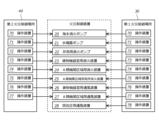
- FIG. 2 is a block diagram of a control system of the ship.
- FIG. 1 is a schematic diagram of the ship 100. As shown in FIG. 1, the ship 100 includes a hull 10, a plurality of fire control devices 20-28, a first fire control location 30, and a second fire control location 40. Below, these components will be described in order.
- the hull 10 includes three areas: a bow area 11 which is the front part of the hull 10; a stern area 12 which is the rear part of the hull 10; and a central area 13 located between the bow area 11 and the stern area 12.
- the bow area 11 contains the living quarters 51 where the crew works and lives.
- the A-class machinery space 52 refers to a place that houses any of the following: (1) an internal combustion engine used for main propulsion, (2) an internal combustion engine with a total output of 375 kW or more used for purposes other than main propulsion, or (3) an oil-fired boiler or fuel oil device, or an inert gas generating device, an incinerator, or other oil-fired equipment other than a boiler, and includes trunks leading to these places.
- the A-class machinery space 52 includes an engine room.
- the A-class machinery space 52 has an engine room lower part 56 located below the upper deck 14 of the stern area 12, and an engine room upper part 57 located above the upper deck 14 of the stern area 12.
- the cargo equipment room 53 is a place where a cargo compressor, a cargo pump, or a cargo process unit (including those that supply gas fuel to the engine room) is located.
- the cargo equipment room 53 is located above the A-class machinery space 52. More precisely, the cargo equipment room 53 is located above the lower engine room 56 of the A-class engine space 52.
- the stern superstructure 54 is located above the lower engine room 56 of the A-class engine space 52, and between the cargo equipment room 53 and the upper engine room 57 of the A-class engine space 52. In other words, the stern superstructure 54 is located aft of the cargo equipment room 53.
- Storage tanks 59 that store liquefied gas are located in the central area 13.
- the number of storage tanks 59 located in the central area 13 is four, but the number of storage tanks 59 located in the central area 13 is not limited.
- equipment other than the storage tanks 59 may be placed in the central area 13.
- the fire control devices 20 to 28 are devices that protect the ship 100 from fire. As shown in Fig. 2, the fire control devices 20 to 28 of this embodiment include a seawater fire pump 20, a water spray pump 21, an emergency fire pump 22, a cargo equipment room fire extinguishing device 23, an A-class machinery space fire extinguishing device 24, an A-class machinery space local fire extinguishing device 25, a cargo equipment room ventilation device 26, an A-class machinery space ventilation device 27, and an accommodation space ventilation device 28.
- the fire control devices are not limited to those described above.
- the seawater fire pump 20 is located in the stern area 12 and supplies seawater via seawater piping 61 to fire hydrants 62 located in the bow area 11, stern area 12, and central area 13. Therefore, the seawater fire pump 20 is a fire control device that protects the equipment located in the bow area 11, stern area 12, and central area 13.
- the water spray pump 21 is located in the stern area 12 and is a pump that supplies seawater or fresh water to the water spray device 64 via the water spray piping 63.
- the water spray device 64 sprays water into the accommodation space 51 located in the bow area 11, the cargo equipment room 53 located in the stern area 12, and the storage tank 59 located in the central area 13. Therefore, the water spray pump 21 is a fire control device that protects the equipment located in the bow area 11, the stern area 12, and the central area 13.
- the emergency fire pump 22 is located in the bow area 11 and supplies water to the water spray device 64 via the water spray piping 63 in the event of an emergency, such as when the seawater fire pump 20 breaks down. Therefore, like the water spray pump 21, the emergency fire pump 22 is also a fire control device that protects the equipment located in the bow area 11, stern area 12, and center area 13.
- the cargo equipment room fire extinguishing system 23 is located in the cargo equipment room 53, and is a device that extinguishes a fire in the cargo equipment room 53 in the event of a fire. Therefore, the cargo equipment room fire extinguishing system 23 is a fire control device that protects equipment located in the stern area 12. Note that the cargo equipment room fire extinguishing system 23 in this embodiment is, for example, a carbon dioxide fire extinguishing system, but the type of cargo equipment room fire extinguishing system 23 is not limited.
- the Class A machinery space fire extinguishing system 24 is a system that is partially located within the Class A machinery space 52 and extinguishes a fire within the Class A machinery space 52 in the event of a fire. Therefore, the Class A machinery space fire extinguishing system 24 is a fire control system that protects equipment located in the stern area 12. Note that the Class A machinery space fire extinguishing system 24 in this embodiment is, for example, a high expansion foam fire extinguishing system, but the type of Class A machinery space fire extinguishing system 24 is not limited.
- the local fire extinguishing system 25 for the A-class machinery space is located in the A-class machinery space 52, and in the event of a fire, extinguishes fires in areas of the A-class machinery space 52 where there is a risk of fire, such as the internal combustion engine, boiler, and furnace. Therefore, the local fire extinguishing system 25 for the A-class machinery space is a fire control device that protects equipment located in the stern area 12.
- the local fire extinguishing system 25 for the A-class machinery space in this embodiment is, for example, a fresh water fire extinguishing system, but the type of the local fire extinguishing system 25 for the A-class machinery space is not limited.
- the cargo equipment room ventilation device 26 is located inside or outside the cargo equipment room 53, and normally ventilates the cargo equipment room 53 by replacing the air inside the cargo equipment room 53 through ventilation openings, and in the event of a fire, blocks the gas inside the cargo equipment room 53 from leaking out to the outside, facilitating fire extinguishing. Therefore, the cargo equipment room ventilation device 26 is a fire control device that protects the equipment located in the stern area 12. Note that the cargo equipment room ventilation device 26 in this embodiment is, for example, an exhaust fan, but the type of cargo equipment room ventilation device 26 is not limited.
- the Class A machinery space ventilation device 27 is located inside or outside the Class A machinery space 52, and is a device that cuts off the air supply to the Class A machinery space 52 in the event of a fire, facilitating fire extinguishing. Therefore, the Class A machinery space ventilation device 27 is a fire control device that protects the equipment located in the stern area 12. Note that the Class A machinery space ventilation device 27 in this embodiment is, for example, an air supply fan, but the type of Class A machinery space ventilation device 27 is not limited.
- the accommodation ventilation device 28 is located inside or outside the accommodation space 51, and is a device that cuts off the air supply to the accommodation space 51 in the event of a fire or gas being detected within the accommodation space 51, and encourages fire extinguishing. Therefore, the accommodation ventilation device 28 is a fire control device that protects the equipment located in the bow area 11. Note that the accommodation ventilation device 28 in this embodiment is, for example, an air supply fan, but the type of accommodation ventilation device 28 is not limited.
- the first fire control location 30 is a control location capable of operating at least some of the fire control devices 20 to 28. In the first fire control location 30 of this embodiment, all of the above-mentioned fire control devices 20 to 28 can be operated. As shown in Fig. 2, operation devices 70 to 78 corresponding to the fire control devices 20 to 28 are installed in the first fire control location 30. When an operator operates each operation device 70 to 78, a control signal is transmitted from each operation device 70 to 78 to the corresponding fire control device 20 to 28, and each fire control device 20 to 28 can be operated.
- the first fire control location 30 in this embodiment is located in the bow area 11, and more specifically, in the accommodation area 51.
- the second fire control location 40 is a control location where at least some of the fire control devices 20 to 28 can be operated. At the second fire control location 40 of this embodiment, the above-mentioned fire control devices 20 to 27 excluding the living space ventilation device 28 can be operated. As shown in Fig. 2, operation devices 70 to 77 corresponding to the fire control devices 20 to 27 are installed at the second fire control location 40. When an operator operates each of the operation devices 70 to 77, a control signal is transmitted from each of the operation devices 70 to 77 to the corresponding fire control device 20 to 27, and each of the fire control devices 20 to 27 can be operated.
- the second fire control location 40 in this embodiment is located in the stern area 12, and more specifically, in the stern superstructure 54.
- the fire control devices 20-28 can be operated from either the first fire control location 30 or the second fire control location 40.
- the fire control devices 20-27 can be operated from multiple fire control locations 30, 40. Therefore, after recognizing the occurrence of a fire, an operator need only head to the nearest fire control location 30, 40, and the time it takes for an operator to confirm the occurrence of a fire and reach the fire control location 30, 40 can be shortened. As a result, fire extinguishing operations can be started promptly.
- the second fire control location 40 located in the stern area 12 it is not possible to operate the above-mentioned fire control devices 20-28, i.e., the accommodation ventilation device 28, that is, the fire control device that only protects the equipment located in the bow area 11, and only the fire control devices 20-27 that protect the equipment located in the stern area 12 can be operated. If a fire breaks out in the bow area 11, a worker who confirms the occurrence of the fire will head to the first fire control location 30 located in the bow area 11, rather than the second fire control location 40 located in the stern area 12. Therefore, even if the second fire control location 40 is configured to be able to operate only the fire control devices 20-27 that protect the equipment located in the stern area 12, there is no delay in the start of fire extinguishing work.
- the second fire control location 40 may be simplified by configuring it to be able to operate only the fire control devices 20-27 whose protection targets include equipment located in the stern area 12.
- the second fire control location 40 may be configured to be able to operate only the fire control devices whose protection targets include at least equipment located in the stern area 12 or the central area 13, rather than being able to operate only the fire control devices 20-27 whose protection targets include equipment located in the stern area 12. Even in this case, the second fire control location 40 can be simplified.
- the first fire control location 30 is located in the bow area 11, and the second fire control location 40 is located in the stern area 12.
- the first fire control location 30 may be located in any of the three areas 11 to 13, and the second fire control location 40 may be located in an area among the three areas 11 to 13 other than the area in which the first fire control location 30 is located.
- the first fire control location 30 may be located in the stern area 12, and the second fire control location 40 may be located in the bow area 11.
- the second fire control location 40 may be able to operate only fire control devices that include in their protected objects at least equipment located in the bow area 11 or the central area 13.
- the ship 100 described above is equipped with a first fire control location 30 and a second fire control location 40, but may also be equipped with a third fire control location in addition to these fire control locations.
- each fire control location may be located in a different area among the three areas 11 to 13 described above.
- the first item disclosed in this specification is a ship comprising a hull including three areas: a bow area, a stern area, and a central area; a plurality of fire control devices located on the hull; a first fire control location capable of operating at least a portion of the plurality of fire control devices and located in any of the three areas; and a second fire control location capable of operating at least a portion of the plurality of fire control devices and located in an area of the three areas other than the area in which the first fire control location is located, wherein the plurality of fire control devices include fire control devices that can be operated from either the first fire control location or the second fire control location.
- This configuration shortens the time it takes for workers to reach the fire control location after confirming the occurrence of a fire, allowing firefighting operations to begin quickly.
- the second item disclosed in this specification is the vessel described in the first item, in which the first fire control location is located in the bow area and the second fire control location is located in the stern area.
- the first and second fire control locations are separated into the bow and stern areas, allowing workers to quickly reach the fire control locations after confirming that a fire has broken out.
- the third item disclosed in this specification is the vessel described in the first item, in which the first fire control location is located in the stern area and the second fire control location is located in the bow area.
- the fourth item disclosed in this specification is the ship described in the second item, in which only the fire control device among the plurality of fire control devices whose protected objects include at least the equipment located in the stern area or the central area can be operated from the second fire control location.
- This configuration allows the second fire control location to be simplified.
- the fifth item disclosed in this specification is the ship described in the third item, in which only the fire control device among the plurality of fire control devices whose protected objects include at least equipment located in the bow area or the central area can be operated from the second fire control location.
- This configuration allows the second fire control location to be simplified.
- the sixth item disclosed in this specification is a vessel as described in the second or fourth item, comprising an accommodation space located in the bow area and an aft superstructure located in the aft area, the first fire control location being located within the accommodation space, and the second fire control location being located within the aft superstructure.
- both the first and second fire control locations are easily accessible to workers, so workers can quickly reach the fire control locations after confirming that a fire has occurred.
- the first item disclosed in this specification is a ship described in any one of the second, fourth, and sixth items, which comprises a storage tank located in the central area for storing liquefied gas, an A-class machinery space located in the stern area and including a propulsion engine, and a cargo equipment room located above the A-class machinery space and including a compressor for compressing vaporized gas, and the second fire control location is located above the A-class machinery space and aft of the cargo equipment room.
- the second fire control location is located near equipment that is likely to cause a large fire in the event of a fire. This makes it possible to prevent the fire from growing larger.
Landscapes
- Engineering & Computer Science (AREA)
- Ocean & Marine Engineering (AREA)
- Chemical & Material Sciences (AREA)
- Combustion & Propulsion (AREA)
- Mechanical Engineering (AREA)
- Health & Medical Sciences (AREA)
- Public Health (AREA)
- Business, Economics & Management (AREA)
- Emergency Management (AREA)
- Fire-Extinguishing By Fire Departments, And Fire-Extinguishing Equipment And Control Thereof (AREA)
Abstract
Description
以下、実施形態に係る船舶100について説明する。はじめに、船舶100の全体構成について説明する。本実施形態の船舶100は、液化ガスを運搬する液化ガス運搬船である。ただし、船舶100は液化ガス運搬船に限定されない。図1は、船舶100の概略図である。図1に示すように、船舶100は、船体10と、複数の火災制御装置20~28と、第1火災制御場所30と、第2火災制御場所40と、を備えている。以下、これらの構成要素について順に説明する。
船体10は、船体10の前方部分にあたる船首エリア11、船体10の後方部分にあたる船尾エリア12、及び、船首エリア11と船尾エリア12の間に位置する中央エリア13の3エリアを含んでいる。
火災制御装置20~28は、火災から船舶100を保護する装置である。図2に示すように、本実施形態の火災制御装置20~28は、海水消火ポンプ20、水噴霧ポンプ21、非常用消火ポンプ22、貨物機器室用消火装置23、A類機関区域用消火装置24、A類機関区域用局所消火装置25、貨物機器室用通風装置26、A類機関区域用通風装置27、及び、居住区用通風装置28を含んでいる。ただし、火災制御装置は、上記のものに限定されない。
第1火災制御場所30は、火災制御装置20~28の少なくとも一部を操作可能な制御場所である。本実施形態の第1火災制御場所30では、上述した火災制御装置20~28の全てを操作することができる。図2に示すように、第1火災制御場所30には、火災制御装置20~28に対応する操作装置70~78が設置されている。作業者が各操作装置70~78を操作することにより、各操作装置70~78から対応する火災制御装置20~28に制御信号が送信され、各火災制御装置20~28を操作することができる。
第2火災制御場所40は、火災制御装置20~28の少なくとも一部を操作可能な制御場所である。本実施形態の第2火災制御場所40では、上述した火災制御装置20~28のうち居住区用通風装置28を除く火災制御装置20~27を操作することができる。図2に示すように、第2火災制御場所40には、火災制御装置20~27に対応する操作装置70~77が設置されている。作業者が各操作装置70~77を操作することにより、各操作装置70~77から対応する火災制御装置20~27に制御信号が送信され、各火災制御装置20~27を操作することができる。
上記の実施形態では、第1火災制御場所30が船首エリア11に位置しており、第2火災制御場所40が船尾エリア12に位置している。ただし、第1火災制御場所30は、3つのエリア11~13のうちのいずれかのエリアに位置し、第2火災制御場所40は、3つのエリア11~13のうち第1火災制御場所30が位置するエリア以外のエリアに位置していてもよい。例えば、第1火災制御場所30が船尾エリア12に位置し、第2火災制御場所40が船首エリア11に位置していてもよい。この場合、第2火災制御場所40は、少なくとも船首エリア11又は中央エリア13に位置する設備を保護対象に含む火災制御装置のみ操作可能であってもよい。
本明細書で開示する第1の項目は、船首エリア、船尾エリア、及び、中央エリアの3エリアを含む船体と、前記船体に位置する複数の火災制御装置と、前記複数の火災制御装置の少なくとも一部を操作可能であって、前記3つのエリアのうちのいずれかのエリアに位置する第1火災制御場所と、前記複数の火災制御装置の少なくとも一部を操作可能であって、前記3つのエリアのうち前記第1火災制御場所が位置するエリア以外のエリアに位置する第2火災制御場所と、を備えており、前記複数の火災制御装置は、前記第1火災制御場所及び前記第2火災制御場所のいずれからでも操作可能な火災制御装置を含む、船舶である。
11 船首エリア
12 船尾エリア
13 中央エリア
20 海水消火ポンプ(火災制御装置)
21 水噴霧ポンプ(火災制御装置)
22 非常用消火ポンプ(火災制御装置)
23 貨物機器室用消火装置(火災制御装置)
24 A類機関区域用消火装置(火災制御装置)
25 A類機関区域用局所消火装置(火災制御装置)
26 貨物機器室用通風装置(火災制御装置)
27 A類機関区域用通風装置(火災制御装置)
28 居住区用通風装置(火災制御装置)
30 第1火災制御場所
40 第2火災制御場所
51 居住区
52 A類機関区域
53 貨物機器室
54 船尾上部構造物
59 貯蔵タンク
100 船舶
Claims (7)
- 船首エリア、船尾エリア、及び、中央エリアの3エリアを含む船体と、
前記船体に位置する複数の火災制御装置と、
前記複数の火災制御装置の少なくとも一部を操作可能であって、前記3つのエリアのうちのいずれかのエリアに位置する第1火災制御場所と、
前記複数の火災制御装置の少なくとも一部を操作可能であって、前記3つのエリアのうち前記第1火災制御場所が位置するエリア以外のエリアに位置する第2火災制御場所と、を備えており、
前記複数の火災制御装置は、前記第1火災制御場所及び前記第2火災制御場所のいずれからでも操作可能な火災制御装置を含む、船舶。 - 前記第1火災制御場所は前記船首エリアに位置しており、
前記第2火災制御場所は前記船尾エリアに位置している、請求項1に記載の船舶。 - 前記第1火災制御場所は前記船尾エリアに位置しており、
前記第2火災制御場所は前記船首エリアに位置している、請求項1に記載の船舶。 - 前記第2火災制御場所からは、前記複数の火災制御装置のうち少なくとも前記船尾エリア又は前記中央エリアに位置する設備を保護対象に含む火災制御装置のみ操作可能である、請求項2に記載の船舶。
- 前記第2火災制御場所からは、前記複数の火災制御装置のうち少なくとも前記船首エリア又は前記中央エリアに位置する設備を保護対象に含む火災制御装置のみ操作可能である、請求項3に記載の船舶。
- 前記船首エリアに位置する居住区と、
前記船尾エリアに位置する船尾上部構造物と、を備え、
前記第1火災制御場所は前記居住区内に位置しており、
前記第2火災制御場所は前記船尾上部構造物内に位置している、請求項2に記載の船舶。 - 前記中央エリアに位置し液化ガスを貯蔵する貯蔵タンクと、
前記船尾エリアに位置し推進機関を含むA類機関区域と、
前記A類機関区域の上方に位置し気化ガスを圧縮する圧縮機を含む貨物機器室と、を備え、
前記第2火災制御場所は前記A類機関区域の上方であって前記貨物機器室の後方に位置している、請求項2に記載の船舶。
Priority Applications (4)
| Application Number | Priority Date | Filing Date | Title |
|---|---|---|---|
| KR1020257020898A KR20250113467A (ko) | 2023-01-10 | 2023-01-10 | 선박 |
| CN202380089163.9A CN120418151A (zh) | 2023-01-10 | 2023-01-10 | 船舶 |
| JP2024569689A JP7909043B2 (ja) | 2023-01-10 | 船舶 | |
| PCT/JP2023/000299 WO2024150271A1 (ja) | 2023-01-10 | 2023-01-10 | 船舶 |
Applications Claiming Priority (1)
| Application Number | Priority Date | Filing Date | Title |
|---|---|---|---|
| PCT/JP2023/000299 WO2024150271A1 (ja) | 2023-01-10 | 2023-01-10 | 船舶 |
Publications (1)
| Publication Number | Publication Date |
|---|---|
| WO2024150271A1 true WO2024150271A1 (ja) | 2024-07-18 |
Family
ID=91896579
Family Applications (1)
| Application Number | Title | Priority Date | Filing Date |
|---|---|---|---|
| PCT/JP2023/000299 Ceased WO2024150271A1 (ja) | 2023-01-10 | 2023-01-10 | 船舶 |
Country Status (3)
| Country | Link |
|---|---|
| KR (1) | KR20250113467A (ja) |
| CN (1) | CN120418151A (ja) |
| WO (1) | WO2024150271A1 (ja) |
Citations (6)
| Publication number | Priority date | Publication date | Assignee | Title |
|---|---|---|---|---|
| JPH07285496A (ja) * | 1994-04-18 | 1995-10-31 | Osaka Shosen Mitsui Senpaku Kk | ばら積船における防災システム |
| US20040099195A1 (en) * | 2002-11-26 | 2004-05-27 | Searle Ronald G. | Shipping methanol for a methanol to olefin unit in non-methanol carriers |
| CN203620122U (zh) * | 2013-11-29 | 2014-06-04 | 大连船舶重工集团有限公司 | 集装箱船应急消防泵系统 |
| JP2015181546A (ja) * | 2014-03-20 | 2015-10-22 | 三井造船株式会社 | 船舶 |
| JP2019189172A (ja) * | 2018-04-27 | 2019-10-31 | 三井E&S造船株式会社 | 洋上浮体構造物 |
| JP2021187190A (ja) * | 2020-05-26 | 2021-12-13 | 三井E&S造船株式会社 | 貨物船 |
-
2023
- 2023-01-10 KR KR1020257020898A patent/KR20250113467A/ko active Pending
- 2023-01-10 WO PCT/JP2023/000299 patent/WO2024150271A1/ja not_active Ceased
- 2023-01-10 CN CN202380089163.9A patent/CN120418151A/zh active Pending
Patent Citations (6)
| Publication number | Priority date | Publication date | Assignee | Title |
|---|---|---|---|---|
| JPH07285496A (ja) * | 1994-04-18 | 1995-10-31 | Osaka Shosen Mitsui Senpaku Kk | ばら積船における防災システム |
| US20040099195A1 (en) * | 2002-11-26 | 2004-05-27 | Searle Ronald G. | Shipping methanol for a methanol to olefin unit in non-methanol carriers |
| CN203620122U (zh) * | 2013-11-29 | 2014-06-04 | 大连船舶重工集团有限公司 | 集装箱船应急消防泵系统 |
| JP2015181546A (ja) * | 2014-03-20 | 2015-10-22 | 三井造船株式会社 | 船舶 |
| JP2019189172A (ja) * | 2018-04-27 | 2019-10-31 | 三井E&S造船株式会社 | 洋上浮体構造物 |
| JP2021187190A (ja) * | 2020-05-26 | 2021-12-13 | 三井E&S造船株式会社 | 貨物船 |
Also Published As
| Publication number | Publication date |
|---|---|
| KR20250113467A (ko) | 2025-07-25 |
| JPWO2024150271A1 (ja) | 2024-07-18 |
| CN120418151A (zh) | 2025-08-01 |
Similar Documents
| Publication | Publication Date | Title |
|---|---|---|
| JP7656599B2 (ja) | 二元燃料バルクキャリア | |
| CN113047994A (zh) | 一种甲醇燃油双燃料船舶 | |
| KR20180012304A (ko) | 선박 | |
| JP2017023735A (ja) | 火災抑制システム、および航空機の火災抑制システムにおける火災抑制剤の放出の制御方法 | |
| JP2008126829A (ja) | 船舶 | |
| JP2015181546A (ja) | 船舶 | |
| JP2019189172A (ja) | 洋上浮体構造物 | |
| KR20110138056A (ko) | 선박의 음성 경보장치 | |
| KR20250113467A (ko) | 선박 | |
| KR102919986B1 (ko) | 선박 | |
| KR20210128528A (ko) | 컨테이너선의 연료가스 공급시스템 | |
| KR102862974B1 (ko) | 선박의 소화 시스템 | |
| JP2008149798A (ja) | 船舶 | |
| Darwin et al. | The development of water mist fire protection systems for US Navy ships | |
| Etemad | Hazard identification (HAZID) of LNG dual-fueled ships operating between the Korean port of Busan and the Iranian port of Bandar Abbas | |
| JP7754702B2 (ja) | 液化ガス運搬船 | |
| Arvidson et al. | Literature study: The performance of carbon dioxide systems on ro-ro vehicle carriers | |
| KR101788754B1 (ko) | 부유 저장식 가스 발전플랜트의 배치구조 | |
| KR20150021300A (ko) | 주소화설비실 및 이를 가지는 lng fpso | |
| KR20210033130A (ko) | 화재 진압 시스템 및 이를 구비하는 부유식 구조물 | |
| KR102527867B1 (ko) | 선박용 소방 시스템 및 이를 구비한 선박 | |
| WO2024157380A1 (ja) | 液化ガス運搬船の消火設備 | |
| KR20250144247A (ko) | 선박 | |
| Casale et al. | Is Your Passive Emergency Fire Protection System Too Passive? | |
| KR20250060274A (ko) | 액화 가스 탱크를 구비한 선박 |
Legal Events
| Date | Code | Title | Description |
|---|---|---|---|
| 121 | Ep: the epo has been informed by wipo that ep was designated in this application |
Ref document number: 23915895 Country of ref document: EP Kind code of ref document: A1 |
|
| WWE | Wipo information: entry into national phase |
Ref document number: 2024569689 Country of ref document: JP |
|
| WWE | Wipo information: entry into national phase |
Ref document number: 1020257020898 Country of ref document: KR |
|
| WWE | Wipo information: entry into national phase |
Ref document number: 202380089163.9 Country of ref document: CN |
|
| WWP | Wipo information: published in national office |
Ref document number: 1020257020898 Country of ref document: KR |
|
| WWP | Wipo information: published in national office |
Ref document number: 202380089163.9 Country of ref document: CN |
|
| NENP | Non-entry into the national phase |
Ref country code: DE |
|
| 122 | Ep: pct application non-entry in european phase |
Ref document number: 23915895 Country of ref document: EP Kind code of ref document: A1 |