WO2024147243A1 - 内視鏡および内視鏡の製造方法 - Google Patents
内視鏡および内視鏡の製造方法 Download PDFInfo
- Publication number
- WO2024147243A1 WO2024147243A1 PCT/JP2023/042532 JP2023042532W WO2024147243A1 WO 2024147243 A1 WO2024147243 A1 WO 2024147243A1 JP 2023042532 W JP2023042532 W JP 2023042532W WO 2024147243 A1 WO2024147243 A1 WO 2024147243A1
- Authority
- WO
- WIPO (PCT)
- Prior art keywords
- light
- resin member
- transparent resin
- endoscope
- emitting unit
- Prior art date
- Legal status (The legal status is an assumption and is not a legal conclusion. Google has not performed a legal analysis and makes no representation as to the accuracy of the status listed.)
- Ceased
Links
Images





Classifications
-
- A—HUMAN NECESSITIES
- A61—MEDICAL OR VETERINARY SCIENCE; HYGIENE
- A61B—DIAGNOSIS; SURGERY; IDENTIFICATION
- A61B1/00—Instruments for performing medical examinations of the interior of cavities or tubes of the body by visual or photographical inspection, e.g. endoscopes; Illuminating arrangements therefor
- A61B1/04—Instruments for performing medical examinations of the interior of cavities or tubes of the body by visual or photographical inspection, e.g. endoscopes; Illuminating arrangements therefor combined with photographic or television appliances
- A61B1/05—Instruments for performing medical examinations of the interior of cavities or tubes of the body by visual or photographical inspection, e.g. endoscopes; Illuminating arrangements therefor combined with photographic or television appliances characterised by the image sensor, e.g. camera, being in the distal end portion
-
- A—HUMAN NECESSITIES
- A61—MEDICAL OR VETERINARY SCIENCE; HYGIENE
- A61B—DIAGNOSIS; SURGERY; IDENTIFICATION
- A61B1/00—Instruments for performing medical examinations of the interior of cavities or tubes of the body by visual or photographical inspection, e.g. endoscopes; Illuminating arrangements therefor
- A61B1/06—Instruments for performing medical examinations of the interior of cavities or tubes of the body by visual or photographical inspection, e.g. endoscopes; Illuminating arrangements therefor with illuminating arrangements
-
- A—HUMAN NECESSITIES
- A61—MEDICAL OR VETERINARY SCIENCE; HYGIENE
- A61B—DIAGNOSIS; SURGERY; IDENTIFICATION
- A61B1/00—Instruments for performing medical examinations of the interior of cavities or tubes of the body by visual or photographical inspection, e.g. endoscopes; Illuminating arrangements therefor
- A61B1/06—Instruments for performing medical examinations of the interior of cavities or tubes of the body by visual or photographical inspection, e.g. endoscopes; Illuminating arrangements therefor with illuminating arrangements
- A61B1/07—Instruments for performing medical examinations of the interior of cavities or tubes of the body by visual or photographical inspection, e.g. endoscopes; Illuminating arrangements therefor with illuminating arrangements using light-conductive means, e.g. optical fibres
Definitions
- Endoscopes have been available for some time, equipped with an objective lens and an illumination lens at the tip, and inserted into the human body to observe the inside of a body cavity while introducing treatment tools to perform treatments inside the body cavity via a treatment tool insertion channel that runs from the proximal side to the tip.
- treatments that use such endoscopes include ESD (endoscopic submucosal dissection) and EMR (endoscopic mucosal resection).
- Patent Document 2 describes an electronic endoscope that includes a hub, a shaft extending from the hub, an expandable distal tip extending from the shaft, an image sensor within the distal tip and having a field of view outside the endoscope, an illumination element within the distal tip and configured to emit light within the field of view of the image sensor, and at least one variable-shape working channel within the distal tip, the working channel adapted to change from an overall non-circular cross-sectional shape to a different cross-sectional shape to accommodate the passage of an instrument.
- the endoscopes described in Patent Documents 1 to 4 have the problem that the illumination provided by the endoscope is not bright enough, making it difficult to observe inside body cavities such as the digestive tract.
- the present invention was made in consideration of the above circumstances, and its purpose is to provide an endoscope and a method for manufacturing an endoscope that can brightly illuminate the inside of a body cavity and make it easy to observe the inside of the body cavity.
- the endoscope according to the embodiment of the present invention that can solve the above problems is as follows.
- An endoscope having an image sensor and a light emitting unit, a transparent resin member fixed to the imaging element and the light emitting unit and through which light irradiated from the light emitting unit can pass;
- the transparent resin member has 1 to 10 bubbles with a major axis of 50 ⁇ m or more and 500 ⁇ m or less in an area of 0.1 mm in length in the longitudinal axis direction of the endoscope.
- the transparent resin member has a central portion which is a circular region whose center is the centroid of the outline of the transparent resin member and whose diameter is half the length of the minor axis of the outline of the transparent resin member, and a peripheral portion which is a region excluding the central portion,
- the imaging device further includes a cylindrical body capable of accommodating the imaging element, the transparent resin member, and the light emitting unit in an inner cavity, An endoscope according to any one of [1] to [4], wherein when the imaging element, the transparent resin member, and the light-emitting section are exposed from the tubular body, the transparent resin member has a contact surface on its outer surface that is capable of coming into contact with a wall of a lumen within a living body.
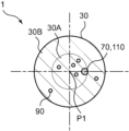
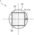
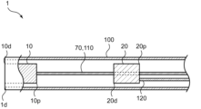
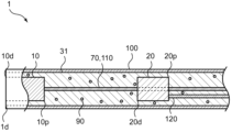
- FIG. 1 illustrates an enlarged plan view of a distal portion of an endoscope in one embodiment of the present invention.
- 2 shows a cross-sectional view of the endoscope shown in FIG. 1 along line II-II.
- 3 shows a cross-sectional view of the endoscope shown in FIG. 1 taken along line III-III.
- 4 shows a cross-sectional view of the endoscope shown in FIG. 1 taken along line IV-IV.
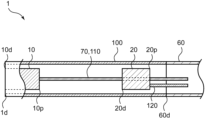
- 5A to 5C are schematic diagrams (partial cross-sectional views) illustrating a process of placing an imaging element and a light emitting unit in an inner cavity of a heat shrink tube according to an embodiment of the present invention.
- FIG. 2 is a schematic diagram (partial cross-sectional view) showing a process of heating a heat shrink tube in one embodiment of the present invention
- FIG. 3A to 3C are schematic diagrams (partial cross-sectional views) illustrating a process of filling a transparent liquid resin into an inner cavity of a heat shrink tube according to an embodiment of the present invention.
- 3A to 3C are schematic diagrams (partial cross-sectional views) illustrating a process for forming bubbles in a transparent liquid resin according to an embodiment of the present invention.
- 5A to 5C are schematic diagrams illustrating a process for removing a heat shrink tube according to an embodiment of the present invention.
- 13A to 13C are schematic diagrams (partial cross-sectional views) illustrating a process of arranging wiring for an imaging element and wiring for a light-emitting unit in an inner cavity of a covering tube according to an embodiment of the present invention.
- the proximal side refers to the side closest to the user in the extension direction of the endoscope 1
- the distal side refers to the side opposite the proximal side, i.e., the side to be treated.
- the extension direction of the endoscope 1 is also referred to as the longitudinal axis direction.
- the right side of the figure is the proximal side
- the left side of the figure is the distal side.
- the endoscope 1 of the present invention has an image sensor 10 and a light emitting unit 20, and has a transparent resin member 30 that is fixed to the image sensor 10 and the light emitting unit 20 and allows the light irradiated from the light emitting unit 20 to pass through.
- the endoscope 1 is a disposable endoscope.
- a disposable endoscope 1 it is possible to prevent infection of the person being observed through the endoscope 1, and it is possible to improve safety.
- the imaging element 10 converts the light of the subject into an electrical signal and outputs it.
- Examples of the imaging element 10 include a CCD (Charge Coupled Device) and a CMOS (Complementary Metal-Oxide Semiconductor).
- the imaging element 10 is preferably provided with a lens. If the imaging element 10 is provided with a lens, it is preferable that the lens of the imaging element 10 is located at the distal end 1d of the endoscope 1. Providing a lens in the imaging element 10 makes it easier to collect light from the subject, making it easier to observe the intravital lumen using the endoscope 1.
- a power supply device that supplies electricity to the light-emitting unit 20 can be connected to the light-emitting unit 20 via wiring 120 of the light-emitting unit 20.
- electricity is supplied from the power supply device via the wiring 120 to the light source that is the light-emitting unit 20, causing the light source to emit light, making it possible for the light-emitting unit 20 to irradiate light.
- the distal end 30d of the transparent resin member 30 is preferably located distal to the proximal end 10p of the imaging element 10. In other words, it is preferable that the transparent resin member 30 is present outside the imaging element 10.
- the transparent resin member 30 is present around the imaging element 10 at the proximal end 10p of the imaging element 10. Therefore, it is possible to increase the contact area between the outer surface of the imaging element 10 and the transparent resin member 30, making it easier to increase the bonding strength, and to provide an endoscope 1 in which the imaging element 10 is less likely to fall off.
- the transparent resin member 30 When the imaging element 10, the transparent resin member 30, and the light-emitting unit 20 are exposed from the cylindrical body 40, the transparent resin member 30 has a contact surface on its outer surface that can come into contact with the tubular wall of the lumen in the living body, so that the imaging element 10, the transparent resin member 30, and the light-emitting unit 20 are exposed. Because the imaging element 10, the transparent resin member 30, and the light emitting unit 20 are exposed, when the endoscope 1 is placed in a body lumen, there is no foreign object between the imaging element 10, the transparent resin member 30, and the light emitting unit 20 and the wall of the body lumen. As a result, the light emitted from the light emitting unit 20 is less likely to be blocked by foreign objects, and the wall of the body lumen can be brightly illuminated, making it easier to observe the inside of the body lumen using the imaging element 10.
- the lower limit of the amount of ultraviolet light contained in the light irradiated from the light-emitting unit 20 is not particularly limited, but can be, for example, 0 ⁇ W/cm 2 or more (including 0 ⁇ W/cm 2 ).
- the amount of ultraviolet light contained in the light irradiated from the light-emitting unit 20 being 0 ⁇ W/cm 2 means that the light irradiated from the light-emitting unit 20 does not contain ultraviolet light.
- the cross-sectional shapes of the imaging element 10 and the light-emitting section 20 are preferably rectangular, and the cross-sectional shape of the transparent resin member 30 is preferably circular.
- the cross-sectional shapes of the imaging element 10 and the light-emitting section 20 rectangular, the contact area between the surfaces of the imaging element 10 and the light-emitting section 20 and the transparent resin member 30 can be increased.
- the bonding strength between the imaging element 10 and the light-emitting section 20 and the transparent resin member 30 can be increased, making it difficult for the imaging element 10 and the light-emitting section 20 to fall off from the transparent resin member 30.
- the average value of the surface roughness Ra of the transparent resin member 30 is preferably 25 ⁇ m or less, more preferably 23 ⁇ m or less, and even more preferably 20 ⁇ m or less.
- the upper limit of the average value of the surface roughness Ra of the transparent resin member 30 is within the above range, the surface of the transparent resin member 30 can be made smooth.
- the lower limit of the average value of the surface roughness Ra of the transparent resin member 30 is not particularly limited, but can be, for example, 0 ⁇ m or more, 0.5 ⁇ m or more, or 1 ⁇ m or more.
- the method for manufacturing the endoscope 1 includes a step of heating the heat shrink tube 100.
- this step may be referred to as the heating step.
- the heating step By heating the heat shrink tube 100, the diameter of the heat shrink tube 100 is reduced.
- the heating step is preferably performed after the positioning step. That is, the heat shrink tube 100 is heated after the image sensor 10 and the light emitting unit 20 are positioned in the inner cavity of the heat shrink tube 100. By performing the heating step after the positioning step, it becomes easier to temporarily fix the positions of the image sensor 10 and the light emitting unit 20 by the reduced diameter heat shrink tube 100.
- the method of manufacturing the endoscope 1 includes a step of filling the inner cavity of the heat shrink tube 100 with a transparent liquid resin 31 that hardens when exposed to ultraviolet light.
- this step may be referred to as the filling step.
- the image sensor 10 and the light emitting section 20 arranged in the inner cavity of the heat shrink tube 100 come into contact with the transparent liquid resin 31.
- the filling step is preferably performed after the heating step. By performing the filling step after the heating step, it is possible to prevent the transparent liquid resin 31 from flowing into unintended locations, and it is possible to improve the manufacturing efficiency of the endoscope 1.
- the process of moving the heat-shrink tube 100 toward the imaging element 10 before the filling process makes it easier to fill the inner cavity of the covering tube 60 with the transparent liquid resin 31.
- the method for manufacturing the endoscope 1 includes a process for forming air bubbles 90 in the transparent liquid resin 31.
- this process may be referred to as the air bubble process.
- the air bubbles 90 are shown enlarged to explain the air bubble process.
- the air bubble forming process may be performed after the filling process or before the filling process.
- the inner cavity of the heat shrink tube 100 may be filled with the transparent liquid resin 31, and then the air bubbles 90 may be formed in the transparent liquid resin 31 in the inner cavity of the heat shrink tube 100, or the air bubbles 90 may be formed in the transparent liquid resin 31, and then the transparent liquid resin 31 containing the air bubbles 90 may be filled into the inner cavity of the heat shrink tube 100.
- the bubble forming process it becomes easier to pour the transparent liquid resin 31 into every corner of the inner cavity of the heat shrink tube 100, and it becomes easier to fill the heat shrink tube 100 sufficiently. As a result, it becomes easier to spread the transparent liquid resin 31 throughout the inner cavity of the heat shrink tube 100, and molding defects of the transparent resin member 30 become less likely to occur.
- Methods for forming bubbles 90 in the transparent liquid resin 31 include, for example, stirring the transparent liquid resin 31 with a rod-shaped object having a blade-shaped portion like a propeller or an implement shaped like a whisk to incorporate gas such as air into the transparent liquid resin 31, inserting a syringe or an air pump to inject gas into the transparent liquid resin 31, and adding a foaming agent to the transparent liquid resin 31 to cause foaming.
- a method for forming bubbles 90 in the transparent liquid resin 31 is preferably stirring the transparent liquid resin 31 with an implement such as a rod-shaped object to incorporate air.
- the method of manufacturing the endoscope 1 includes a step of irradiating the transparent liquid resin 31 with ultraviolet light to form the transparent resin member 30.
- this step may be referred to as the forming step.
- the forming step is carried out after the filling step.
- the transparent liquid resin 31 is filled into the inner cavity of the heat shrink tube 100, and then irradiated with ultraviolet light, whereby the transparent liquid resin 31 hardens and the transparent resin member 30 can be formed.
- the method for manufacturing the endoscope 1 includes a step of removing the heat shrink tube 100.
- this step may be referred to as the removal step.
- the removal step is performed after the formation step.
- the transparent liquid resin 31 filled in the inner cavity of the heat shrink tube 100 is cured by ultraviolet irradiation to form the transparent resin member 30.
- the heat shrink tube 100 is present outside the transparent resin member 30 formed in the formation step.
- the heat shrink tube 100 is present outside the transparent resin member 30, it may be difficult for the light irradiated from the light emitting unit 20 to pass through the transparent resin member 30, or the sliding property of the outer surface of the transparent resin member 30 may be reduced, thereby reducing the passability to the lumen inside the living body. Therefore, in the removal step, the heat shrink tube 100 present outside the transparent resin member 30 is removed.
- Methods for removing the heat shrink tube 100 in the removal process include, for example, making an incision in the heat shrink tube 100 using a knife or the like to remove the heat shrink tube 100, scraping off the heat shrink tube 100 using a file or the like, and removing the heat shrink tube 100 by contacting the heat shrink tube 100 with a fluid that melts the heat shrink tube 100.
- the heat shrink tube 100 allows ultraviolet light to pass through, and in the process of irradiating the transparent liquid resin 31 with ultraviolet light to form the transparent resin member 30, it is preferable to irradiate the heat shrink tube 100 with ultraviolet light from the outside.
- By irradiating the heat shrink tube 100 with ultraviolet light from the outside in the forming process it becomes easier to irradiate the transparent liquid resin 31 filled in the inner cavity of the heat shrink tube 100 with ultraviolet light. As a result, it becomes easier to form the transparent resin member 30, and it becomes possible to improve the efficiency of the forming process.
- the heat shrink tube 100 is preferably capable of transmitting 50% or more of the irradiated ultraviolet light, more preferably 60% or more, and even more preferably 70% or more.
- the lower limit of the percentage of ultraviolet light that can be transmitted through the heat shrink tube 100 is not particularly limited, and can be, for example, 100% or less.
- a core material 70 is disposed in the inner cavity of the heat shrink tube 100, and in the process of forming bubbles 90 in the transparent liquid resin 31, it is preferable to move the core material 70.
- the core material 70 is disposed in the inner cavity of the heat shrink tube 100, and in the bubble process, the core material 70 disposed in the inner cavity of the heat shrink tube 100 is moved, whereby bubbles 90 can be formed in the transparent liquid resin 31 in the inner cavity of the heat shrink tube 100 by the movement of the core material 70. Therefore, the bubble process can be performed efficiently, and the manufacturing efficiency of the endoscope 1 can be improved.
- the movement of the core material 70 in the bubble process may be in the longitudinal direction of the heat shrink tube 100, in the radial direction of the heat shrink tube 100, or in the circumferential direction of the heat shrink tube 100.
- the direction of movement of the core material 70 in the bubble process may be any one of these directions, or a combination of two or more of these directions.
- the movement of the core material 70 in the bubble process is preferably in a direction including at least one of the radial and circumferential components of the heat shrink tube 100.
- the manufacturing method of the endoscope 1 includes a step of arranging the covering tube 60 proximal to the light emitting unit 20 and a step of inserting the wiring 110 of the image sensor 10 and the wiring 120 of the light emitting unit 20 into the cavity of the covering tube 60 before the step of filling the cavity of the heat shrink tube 100 with the transparent liquid resin 31, and preferably includes a step of filling the cavity of the distal end 60d of the covering tube 60 with the transparent liquid resin 31 before the step of irradiating the transparent liquid resin 31 with ultraviolet light to form the transparent resin member 30.
- the step of arranging the covering tube 60 proximal to the light emitting unit 20 is sometimes referred to as the covering tube arrangement step
- the step of inserting the wiring 110 of the image sensor 10 and the wiring 120 of the light emitting unit 20 into the cavity of the covering tube 60 is sometimes referred to as the wiring insertion step
- the step of filling the cavity of the distal end 60d of the covering tube 60 with the transparent liquid resin 31 is sometimes referred to as the covering tube filling step.
- the manufacturing method of the endoscope 1 it is preferable to perform the covering tube arrangement step and the wiring insertion step, and then the filling step of filling the inner cavity of the heat shrink tube 100 with the transparent liquid resin 31, and it is preferable to perform the covering tube filling step of filling the inner cavity of the distal end 60d of the covering tube 60 with the transparent liquid resin 31, and then the forming step.
- the covering tube arrangement step and the wiring insertion step it is easy to align the positions of the wiring 110 of the image sensor 10 and the wiring 120 of the light emitting unit 20, and it is easy to fill the inner cavity of the heat shrink tube 100 with the transparent liquid resin 31.
- the transparent resin member 30 extends to the inner cavity of the distal end 60d of the covering tube 60, and the bonding strength between the transparent resin member 30 and the covering tube 60 can be increased, making it difficult for the transparent resin member 30 to come off the covering tube 60.
- Both the covering tube positioning step and the wiring insertion step are preferably performed before the filling step.
- the covering tube positioning step may be performed before or after the wiring insertion step.
- a step of placing the covering tube 60 proximal to the light-emitting unit 20 may be performed after a step of inserting the wiring 110 of the imaging element 10 and the wiring 120 of the light-emitting unit 20 into the inner cavity of the covering tube 60, or a step of inserting the wiring 110 of the imaging element 10 and the wiring 120 of the light-emitting unit 20 into the inner cavity of the covering tube 60 may be performed after a step of placing the covering tube 60 proximal to the light-emitting unit 20.
- the step of filling the inside of the covering tube may be performed before or after the filling step.
- the step of filling the cavity of the distal end 60d of the covering tube 60 with the transparent liquid resin 31 may be performed after the step of filling the cavity of the heat shrink tube 100 with the transparent liquid resin 31, or the step of filling the cavity of the heat shrink tube 100 with the transparent liquid resin 31 may be performed after the step of filling the cavity of the distal end 60d of the covering tube 60 with the transparent liquid resin 31.
- the inner cavity of the distal end 60d of the covering tube 60 is filled with the transparent liquid resin 31 while the wiring 110 of the imaging element 10 and the wiring 120 of the light emitting unit 20 are inserted into the inner cavity of the covering tube 60, so that the transparent liquid resin 31 can be easily retained in the inner cavity of the distal end 60d of the covering tube 60.
- the process of filling the inner cavity of the heat shrink tube 100 with the transparent liquid resin 31 and the process of irradiating the transparent liquid resin 31 with ultraviolet light to form the transparent resin member 30 are preferably carried out under negative pressure conditions.
- By carrying out the filling process and the forming process under negative pressure conditions it becomes easier to adjust the number and size of the air bubbles 90 in the transparent liquid resin 31, making it easier to obtain a transparent resin member 30 with the desired structure.
Landscapes
- Health & Medical Sciences (AREA)
- Life Sciences & Earth Sciences (AREA)
- Surgery (AREA)
- Nuclear Medicine, Radiotherapy & Molecular Imaging (AREA)
- Biomedical Technology (AREA)
- Optics & Photonics (AREA)
- Pathology (AREA)
- Radiology & Medical Imaging (AREA)
- Biophysics (AREA)
- Engineering & Computer Science (AREA)
- Physics & Mathematics (AREA)
- Heart & Thoracic Surgery (AREA)
- Medical Informatics (AREA)
- Molecular Biology (AREA)
- Animal Behavior & Ethology (AREA)
- General Health & Medical Sciences (AREA)
- Public Health (AREA)
- Veterinary Medicine (AREA)
- Endoscopes (AREA)
Abstract
Description
[1]撮像素子と発光部とを有する内視鏡であって、
前記撮像素子および前記発光部に固定されており、前記発光部から照射される光が通過可能である透明樹脂部材を有し、
前記透明樹脂部材は、前記内視鏡の長手軸方向における長さが0.1mmの領域において、長径が50μm以上500μm以下である気泡を1個以上10個以下有している内視鏡。
[2]前記内視鏡の長手軸方向における前記透明樹脂部材の長さの中点での前記長手軸方向に垂直な断面において、前記透明樹脂部材は、前記透明樹脂部材の外形の図心を中心とし、前記透明樹脂部材の外形の短径の長さの半分を直径とした円の領域である中央部と、前記中央部を除いた領域である周縁部と、を有しており、
前記中央部が有している前記気泡の数は、前記周縁部が有している気泡の数よりも多い[1]に記載の内視鏡。
[3]前記透明樹脂部材は、前記撮像素子の遠位端よりも近位側であって、前記発光部の近位端よりも遠位側にあり、
前記透明樹脂部材は、前記撮像素子側に位置する遠位領域と、前記発光部側に位置する近位領域と、前記遠位領域よりも近位側かつ前記近位領域よりも遠位側に位置する中間領域と、を有しており、
前記中間領域が有している前記気泡の数は、前記遠位領域が有している前記気泡の数よりも多く、
前記近位領域が有している前記気泡の数は、前記中間領域が有している前記気泡の数よりも多い[1]または[2]に記載の内視鏡。
[4]前記透明樹脂部材を構成する材料は、紫外線硬化樹脂を含んでいる[1]~[3]のいずれかに記載の内視鏡。
[5]前記撮像素子、前記透明樹脂部材、および前記発光部を内腔に収容可能である筒状体をさらに有し、
前記撮像素子、前記透明樹脂部材、および前記発光部が前記筒状体から露出した状態において、前記透明樹脂部材は、外表面に生体内管腔の管壁と接触可能である接触面を有している[1]~[4]のいずれかに記載の内視鏡。
[6]前記透明樹脂部材の内部であって、前記撮像素子よりも近位側かつ前記発光部よりも遠位側に、前記発光部から照射される光を反射する反射材が配置されている[1]~[5]のいずれかに記載の内視鏡。
[7]前記発光部から照射される光に含まれる紫外線量は、1μW/cm2以下である[1]~[6]のいずれかに記載の内視鏡。
[8]前記発光部の遠位端よりも近位側に被覆チューブをさらに有し、
前記透明樹脂部材の内部に芯材が配置されており、
前記芯材は、少なくとも前記撮像素子の近位端から前記被覆チューブの遠位端よりも近位側まで延在している[1]~[7]のいずれかに記載の内視鏡。
[9]前記撮像素子および前記発光部の少なくとも一方は、前記内視鏡の長手軸方向に垂直な方向へ延在する溝が形成されている[1]~[8]のいずれかに記載の内視鏡。
[10]前記内視鏡の長手軸方向に垂直な断面において、前記撮像素子および前記発光部の断面形状は、矩形であり、前記透明樹脂部材の断面形状は、円形である[1]~[9]のいずれかに記載の内視鏡。
[11]前記透明樹脂部材の表面粗さRaの平均値は、25μm以下である[1]~[10]のいずれかに記載の内視鏡。
[12]撮像素子と、発光部と、前記発光部から照射される光が通過可能であって長手軸方向における長さが0.1mmの領域において長径が50μm以上500μm以下の気泡を1個以上10個以下有している透明樹脂部材と、を有する内視鏡を製造する方法であって、
熱収縮チューブの内腔に前記撮像素子および前記発光部を配置する工程と、
前記熱収縮チューブを加熱する工程と、
前記熱収縮チューブの内腔に、紫外線照射によって硬化する透明液状樹脂を充填する工程と、
前記透明液状樹脂内に気泡を形成する工程と、
前記透明液状樹脂に紫外線を照射して前記透明樹脂部材を形成する工程と、
前記熱収縮チューブを除去する工程と、を有する製造方法。
[13]前記熱収縮チューブは、紫外線が通過可能であり、
前記透明液状樹脂に紫外線を照射して前記透明樹脂部材を形成する工程において、前記熱収縮チューブの外方から紫外線の照射を行う[12]に記載の製造方法。
[14]前記熱収縮チューブの内腔に前記透明液状樹脂を充填する工程において、前記熱収縮チューブの内腔に芯材が配置されており、
前記透明液状樹脂内に気泡を形成する工程において、前記芯材を移動させる[12]または[13]に記載の製造方法。
[15]前記熱収縮チューブの内腔に前記透明液状樹脂を充填する工程の前に、前記発光部よりも近位側に被覆チューブを配置する工程と、前記被覆チューブの内腔に前記撮像素子の配線および前記発光部の配線を挿通する工程と、を有し、
前記透明液状樹脂に紫外線を照射して前記透明樹脂部材を形成する工程の前に、前記被覆チューブの遠位端の内腔に前記透明液状樹脂を充填する工程を有している[12]~[14]のいずれかに記載の製造方法。
1d:内視鏡の遠位端
10:撮像素子
10d:撮像素子の遠位端
10p:撮像素子の近位端
20:発光部
20d:発光部の遠位端
20p:発光部の近位端
30:透明樹脂部材
30d:透明樹脂部材の遠位端
30p:透明樹脂部材の近位端
30A:中央部
30B:周縁部
30C:遠位領域
30D:近位領域
30E:中間領域
31:透明液状樹脂
40:筒状体
40d:筒状体の遠位端
50:反射材
60:被覆チューブ
60d:被覆チューブの遠位端
70:芯材
80:溝
90:気泡
100:熱収縮チューブ
110:撮像素子の配線
120:発光部の配線
A1:内視鏡の長手軸方向における長さが0.1mmの領域
P1:透明樹脂部材の外形の図心
Claims (15)
- 撮像素子と発光部とを有する内視鏡であって、
前記撮像素子および前記発光部に固定されており、前記発光部から照射される光が通過可能である透明樹脂部材を有し、
前記透明樹脂部材は、前記内視鏡の長手軸方向における長さが0.1mmの領域において、長径が50μm以上500μm以下である気泡を1個以上10個以下有している内視鏡。 - 前記内視鏡の長手軸方向における前記透明樹脂部材の長さの中点での前記長手軸方向に垂直な断面において、前記透明樹脂部材は、前記透明樹脂部材の外形の図心を中心とし、前記透明樹脂部材の外形の短径の長さの半分を直径とした円の領域である中央部と、前記中央部を除いた領域である周縁部と、を有しており、
前記中央部が有している前記気泡の数は、前記周縁部が有している気泡の数よりも多い請求項1に記載の内視鏡。 - 前記透明樹脂部材は、前記撮像素子の遠位端よりも近位側であって、前記発光部の近位端よりも遠位側にあり、
前記透明樹脂部材は、前記撮像素子側に位置する遠位領域と、前記発光部側に位置する近位領域と、前記遠位領域よりも近位側かつ前記近位領域よりも遠位側に位置する中間領域と、を有しており、
前記中間領域が有している前記気泡の数は、前記遠位領域が有している前記気泡の数よりも多く、
前記近位領域が有している前記気泡の数は、前記中間領域が有している前記気泡の数よりも多い請求項1または2に記載の内視鏡。 - 前記透明樹脂部材を構成する材料は、紫外線硬化樹脂を含んでいる請求項1または2に記載の内視鏡。
- 前記撮像素子、前記透明樹脂部材、および前記発光部を内腔に収容可能である筒状体をさらに有し、
前記撮像素子、前記透明樹脂部材、および前記発光部が前記筒状体から露出した状態において、前記透明樹脂部材は、外表面に生体内管腔の管壁と接触可能である接触面を有している請求項1または2に記載の内視鏡。 - 前記透明樹脂部材の内部であって、前記撮像素子よりも近位側かつ前記発光部よりも遠位側に、前記発光部から照射される光を反射する反射材が配置されている請求項1または2に記載の内視鏡。
- 前記発光部から照射される光に含まれる紫外線量は、1μW/cm2以下である請求項1または2に記載の内視鏡。
- 前記発光部の遠位端よりも近位側に被覆チューブをさらに有し、
前記透明樹脂部材の内部に芯材が配置されており、
前記芯材は、少なくとも前記撮像素子の近位端から前記被覆チューブの遠位端よりも近位側まで延在している請求項1または2に記載の内視鏡。 - 前記撮像素子および前記発光部の少なくとも一方は、前記内視鏡の長手軸方向に垂直な方向へ延在する溝が形成されている請求項1または2に記載の内視鏡。
- 前記内視鏡の長手軸方向に垂直な断面において、前記撮像素子および前記発光部の断面形状は、矩形であり、前記透明樹脂部材の断面形状は、円形である請求項1または2に記載の内視鏡。
- 前記透明樹脂部材の表面粗さRaの平均値は、25μm以下である請求項1または2に記載の内視鏡。
- 撮像素子と、発光部と、前記発光部から照射される光が通過可能であって長手軸方向における長さが0.1mmの領域において長径が50μm以上500μm以下の気泡を1個以上10個以下有している透明樹脂部材と、を有する内視鏡を製造する方法であって、
熱収縮チューブの内腔に前記撮像素子および前記発光部を配置する工程と、
前記熱収縮チューブを加熱する工程と、
前記熱収縮チューブの内腔に、紫外線照射によって硬化する透明液状樹脂を充填する工程と、
前記透明液状樹脂内に気泡を形成する工程と、
前記透明液状樹脂に紫外線を照射して前記透明樹脂部材を形成する工程と、
前記熱収縮チューブを除去する工程と、を有する製造方法。 - 前記熱収縮チューブは、紫外線が通過可能であり、
前記透明液状樹脂に紫外線を照射して前記透明樹脂部材を形成する工程において、前記熱収縮チューブの外方から紫外線の照射を行う請求項12に記載の製造方法。 - 前記熱収縮チューブの内腔に前記透明液状樹脂を充填する工程において、前記熱収縮チューブの内腔に芯材が配置されており、
前記透明液状樹脂内に気泡を形成する工程において、前記芯材を移動させる請求項12または13に記載の製造方法。 - 前記熱収縮チューブの内腔に前記透明液状樹脂を充填する工程の前に、前記発光部よりも近位側に被覆チューブを配置する工程と、前記被覆チューブの内腔に前記撮像素子の配線および前記発光部の配線を挿通する工程と、を有し、
前記透明液状樹脂に紫外線を照射して前記透明樹脂部材を形成する工程の前に、前記被覆チューブの遠位端の内腔に前記透明液状樹脂を充填する工程を有している請求項12または13に記載の製造方法。
Priority Applications (2)
| Application Number | Priority Date | Filing Date | Title |
|---|---|---|---|
| CN202380088728.1A CN120417826A (zh) | 2023-01-05 | 2023-11-28 | 内窥镜以及内窥镜的制造方法 |
| JP2024568705A JPWO2024147243A1 (ja) | 2023-01-05 | 2023-11-28 |
Applications Claiming Priority (2)
| Application Number | Priority Date | Filing Date | Title |
|---|---|---|---|
| JP2023000667 | 2023-01-05 | ||
| JP2023-000667 | 2023-01-05 |
Publications (1)
| Publication Number | Publication Date |
|---|---|
| WO2024147243A1 true WO2024147243A1 (ja) | 2024-07-11 |
Family
ID=91803860
Family Applications (1)
| Application Number | Title | Priority Date | Filing Date |
|---|---|---|---|
| PCT/JP2023/042532 Ceased WO2024147243A1 (ja) | 2023-01-05 | 2023-11-28 | 内視鏡および内視鏡の製造方法 |
Country Status (3)
| Country | Link |
|---|---|
| JP (1) | JPWO2024147243A1 (ja) |
| CN (1) | CN120417826A (ja) |
| WO (1) | WO2024147243A1 (ja) |
Citations (5)
| Publication number | Priority date | Publication date | Assignee | Title |
|---|---|---|---|---|
| JPH0759727A (ja) * | 1993-08-26 | 1995-03-07 | Olympus Optical Co Ltd | 内視鏡カバー方式の内視鏡 |
| JP2009125528A (ja) * | 2007-11-28 | 2009-06-11 | Chinontec Kk | 内視鏡および内視鏡の製造方法 |
| US20170176660A1 (en) * | 2015-12-18 | 2017-06-22 | Novartis Ag | Diverging Light from Fiber Optics Illumination Delivery System |
| WO2020070862A1 (ja) * | 2018-10-04 | 2020-04-09 | オリンパス株式会社 | 内視鏡の先端部 |
| CN211357333U (zh) * | 2019-12-31 | 2020-08-28 | 李羿贤 | 可发光导尿管 |
-
2023
- 2023-11-28 CN CN202380088728.1A patent/CN120417826A/zh active Pending
- 2023-11-28 WO PCT/JP2023/042532 patent/WO2024147243A1/ja not_active Ceased
- 2023-11-28 JP JP2024568705A patent/JPWO2024147243A1/ja active Pending
Patent Citations (5)
| Publication number | Priority date | Publication date | Assignee | Title |
|---|---|---|---|---|
| JPH0759727A (ja) * | 1993-08-26 | 1995-03-07 | Olympus Optical Co Ltd | 内視鏡カバー方式の内視鏡 |
| JP2009125528A (ja) * | 2007-11-28 | 2009-06-11 | Chinontec Kk | 内視鏡および内視鏡の製造方法 |
| US20170176660A1 (en) * | 2015-12-18 | 2017-06-22 | Novartis Ag | Diverging Light from Fiber Optics Illumination Delivery System |
| WO2020070862A1 (ja) * | 2018-10-04 | 2020-04-09 | オリンパス株式会社 | 内視鏡の先端部 |
| CN211357333U (zh) * | 2019-12-31 | 2020-08-28 | 李羿贤 | 可发光导尿管 |
Also Published As
| Publication number | Publication date |
|---|---|
| CN120417826A (zh) | 2025-08-01 |
| JPWO2024147243A1 (ja) | 2024-07-11 |
Similar Documents
| Publication | Publication Date | Title |
|---|---|---|
| EP2987450B1 (en) | Medical device light source | |
| US20220226665A1 (en) | Light therapy diagnostic device and method for operating the same | |
| JP7384814B2 (ja) | 光照射医療装置 | |
| WO2006038739A1 (ja) | 光により過屈曲する細管 | |
| CN114173691B (zh) | 光照射医疗装置 | |
| JP2010529885A (ja) | 可撓赤外線供給装置および方法 | |
| JP2022516171A (ja) | 徹照による管腔内でのチューブの位置決め | |
| JP2024125144A (ja) | 光照射デバイスおよび光照射システム | |
| WO2024147243A1 (ja) | 内視鏡および内視鏡の製造方法 | |
| US12239416B2 (en) | Light therapy diagnostic device and method for operating the same | |
| JP2024097237A (ja) | 内視鏡および内視鏡の製造方法 | |
| CN210055945U (zh) | 一种带有一次性护套管的内窥镜 | |
| JP7773481B2 (ja) | 光照射医療装置 | |
| JP2024051066A (ja) | バルーンカテーテル | |
| WO2023047711A1 (ja) | 光照射医療装置 | |
| JP7718934B2 (ja) | 光照射医療装置 | |
| JP7687889B2 (ja) | 光照射医療装置 | |
| JP7807329B2 (ja) | 光照射医療装置 | |
| WO2023281918A1 (ja) | 光照射医療装置 | |
| JP2024136907A (ja) | 光照射医療装置 | |
| WO2026079111A1 (ja) | 内視鏡の製造方法、及び内視鏡 | |
| JP7807328B2 (ja) | 光照射医療装置 | |
| JP2024136905A (ja) | 光照射医療装置 | |
| WO2022181133A1 (ja) | 内視鏡用光照射装置 | |
| JP2024136906A (ja) | 光照射医療装置 |
Legal Events
| Date | Code | Title | Description |
|---|---|---|---|
| 121 | Ep: the epo has been informed by wipo that ep was designated in this application |
Ref document number: 23914731 Country of ref document: EP Kind code of ref document: A1 |
|
| WWE | Wipo information: entry into national phase |
Ref document number: 2024568705 Country of ref document: JP |
|
| WWE | Wipo information: entry into national phase |
Ref document number: 202380088728.1 Country of ref document: CN |
|
| WWP | Wipo information: published in national office |
Ref document number: 202380088728.1 Country of ref document: CN |
|
| NENP | Non-entry into the national phase |
Ref country code: DE |
|
| 122 | Ep: pct application non-entry in european phase |
Ref document number: 23914731 Country of ref document: EP Kind code of ref document: A1 |