WO2024147237A1 - 電波センサの設定装置、電波センサ、電波センサの設定方法、及びコンピュータプログラム - Google Patents
電波センサの設定装置、電波センサ、電波センサの設定方法、及びコンピュータプログラム Download PDFInfo
- Publication number
- WO2024147237A1 WO2024147237A1 PCT/JP2023/042105 JP2023042105W WO2024147237A1 WO 2024147237 A1 WO2024147237 A1 WO 2024147237A1 JP 2023042105 W JP2023042105 W JP 2023042105W WO 2024147237 A1 WO2024147237 A1 WO 2024147237A1
- Authority
- WO
- WIPO (PCT)
- Prior art keywords
- area
- radio wave
- wave sensor
- crosswalk
- movement trajectory
- Prior art date
- Legal status (The legal status is an assumption and is not a legal conclusion. Google has not performed a legal analysis and makes no representation as to the accuracy of the status listed.)
- Ceased
Links
Images





Classifications
-
- G—PHYSICS
- G01—MEASURING; TESTING
- G01S—RADIO DIRECTION-FINDING; RADIO NAVIGATION; DETERMINING DISTANCE OR VELOCITY BY USE OF RADIO WAVES; LOCATING OR PRESENCE-DETECTING BY USE OF THE REFLECTION OR RERADIATION OF RADIO WAVES; ANALOGOUS ARRANGEMENTS USING OTHER WAVES
- G01S13/00—Systems using the reflection or reradiation of radio waves, e.g. radar systems; Analogous systems using reflection or reradiation of waves whose nature or wavelength is irrelevant or unspecified
- G01S13/88—Radar or analogous systems specially adapted for specific applications
- G01S13/91—Radar or analogous systems specially adapted for specific applications for traffic control
-
- G—PHYSICS
- G01—MEASURING; TESTING
- G01S—RADIO DIRECTION-FINDING; RADIO NAVIGATION; DETERMINING DISTANCE OR VELOCITY BY USE OF RADIO WAVES; LOCATING OR PRESENCE-DETECTING BY USE OF THE REFLECTION OR RERADIATION OF RADIO WAVES; ANALOGOUS ARRANGEMENTS USING OTHER WAVES
- G01S13/00—Systems using the reflection or reradiation of radio waves, e.g. radar systems; Analogous systems using reflection or reradiation of waves whose nature or wavelength is irrelevant or unspecified
- G01S13/88—Radar or analogous systems specially adapted for specific applications
- G01S13/93—Radar or analogous systems specially adapted for specific applications for anti-collision purposes
- G01S13/931—Radar or analogous systems specially adapted for specific applications for anti-collision purposes of land vehicles
-
- G—PHYSICS
- G08—SIGNALLING
- G08G—TRAFFIC CONTROL SYSTEMS
- G08G1/00—Traffic control systems for road vehicles
- G08G1/01—Detecting movement of traffic to be counted or controlled
- G08G1/042—Detecting movement of traffic to be counted or controlled using inductive or magnetic detectors
Definitions
- a computer program is a computer program for setting up a radio wave sensor that detects objects on a crosswalk, and causes a computer to execute the steps of acquiring detection results of an object moving on the crosswalk by the radio wave sensor, generating a movement trajectory of the object in a coordinate space preset in the radio wave sensor based on the detection results, and determining a detection area corresponding to the crosswalk in the coordinate space based on the movement trajectory of the object, the detection area including a first area including the crosswalk, and the determining step including determining a boundary line between the first area and a second area where pedestrians wait to cross the crosswalk based on a movement trajectory of a vehicle traveling on a first roadway that partially overlaps with the crosswalk.
- a corner may be cut at the connection point of two roadways. Therefore, the boundary between the pedestrian crossing area overlapping the roadway and the waiting area overlapping the sidewalk is not necessarily a straight line. If the boundary between the pedestrian crossing area and the waiting area is not accurately determined in the detection area of the radio wave sensor, it is not possible to accurately distinguish between pedestrians crossing the crosswalk and pedestrians waiting in the waiting area.
- the determination unit may further include the second area. With this configuration, the boundary between the first area and the second area can be determined more accurately.
- the movement trajectory of a vehicle turning right or left on the incoming lane to enter the second roadway has a shape that follows the outer edge of the connection point between the second roadway and the incoming lane. Therefore, the boundary line between the first area and the first waiting area can be correctly determined.
- the movement trajectory of a vehicle turning right or left on the second roadway and entering the exit lane follows the outer edge of the connection between the second roadway and the exit lane. Therefore, the boundary between the first area and the second waiting area can be correctly determined.
- the setting device may further include an identification unit that identifies an object whose moving direction is indefinite based on the multiple detection results acquired by the acquisition unit from the radio wave sensor, and the determination unit may determine the boundary line based on the position of the object identified by the identification unit.
- the identification unit may determine the boundary line based on the position of the object identified by the identification unit.
- Pedestrians waiting to cross a pedestrian crossing tend to stop in a fixed position or frequently change their moving direction. Therefore, an object whose moving direction is not fixed (i.e., indefinite) is likely to be a pedestrian waiting to cross a pedestrian crossing. Therefore, the boundary line between the first area and the second area can be accurately determined based on the position of the object whose moving direction is indefinite.
- the determination unit may determine the position of the boundary line based on the position of the object identified by the identification unit. A pedestrian waiting to cross the crosswalk is likely to remain within the second area. Therefore, the position of the boundary line between the first area and the second area can be accurately determined based on the position of an object whose moving direction is uncertain.
- the setting device may further include a display control unit that causes a display device to display the boundary line determined by the determination unit and the movement trajectory of the object generated by the generation unit. This allows the user to check whether the boundary line has been accurately determined based on the movement trajectory.
- the method of setting the radio wave sensor includes the steps of acquiring detection results of an object moving on a crosswalk by the radio wave sensor, generating a movement trajectory of the object in a coordinate space set in the radio wave sensor based on the detection results, and determining a detection area corresponding to the crosswalk in the coordinate space based on the movement trajectory of the object, the detection area including a first area including the crosswalk, and the determining step including determining a boundary line between the first area and a second area where pedestrians wait to cross the crosswalk based on a movement trajectory of a vehicle traveling on a first roadway that partially overlaps with the crosswalk.
- the boundary line between the first area and the second area can be correctly determined based on a movement trajectory that has a shape that follows the boundary line between the first area included in the roadway and the second area included in the sidewalk.
- a computer program is a computer program for setting a radio wave sensor that detects an object on a crosswalk, and causes a computer to execute the steps of acquiring detection results of an object moving on the crosswalk by the radio wave sensor, generating a movement trajectory of the object in a coordinate space preset in the radio wave sensor based on the detection results, and determining a detection area corresponding to the crosswalk in the coordinate space based on the movement trajectory of the object, the detection area including a first area including the crosswalk, and the determining step including determining a boundary line between the first area and a second area where pedestrians wait to cross the crosswalk based on a movement trajectory of a vehicle traveling on a first roadway that partially overlaps with the crosswalk.
- the boundary line between the first area and the second area can be correctly determined based on a movement trajectory that has a shape that follows the boundary line between the first area included in the roadway and the second area included in the sidewalk.
- the detection area may further include the second area.
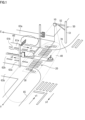
- An infrastructure radio wave sensor 10 is a radio wave radar for monitoring traffic.
- the infrastructure radio wave sensor 10 detects objects (pedestrians, bicycles, vehicles) on a crosswalk 20.
- the infrastructure radio wave sensor 10 is, for example, a millimeter wave radar.
- the radio wave irradiation range 40 does not have to include a range in which the infrastructure radio wave sensor 10 cannot detect an object even if it can irradiate radio waves.
- the radio wave irradiation range 40 is not limited to this, and may be the entire range in which the infrastructure radio wave sensor 10 can irradiate radio waves.
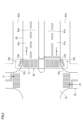
- the incoming lane 61a which is close to the sidewalk 63a, is a lane for going straight and turning left. Vehicles traveling on the incoming lane 61a in the x1 direction either go straight through the intersection 70 or turn left (changing their direction of travel in the y1 direction) to enter the roadway 65.
- the incoming lane 61b which is away from the sidewalk, is a lane for going straight and turning right. Vehicles traveling on the incoming lane 61b in the x1 direction either go straight through the intersection 70 or turn right (changing their direction of travel in the y2 direction) to enter the roadway 65.
- the crosswalk 20 is provided in the range from the straight portion of the roadway 60 to the middle of the corner cuttings 61c and 62c. In other words, the crosswalk 20 includes a part of each of the corner cuttings 61c and 62c.
- the boundary line 33a between the zebra area 31 and the waiting area 32a is set to a shape that follows the boundary line between the roadway 60 and the sidewalk 63a.
- the boundary line 33b between the zebra area 31 and the waiting area 32b is set to a shape that follows the boundary line between the roadway 60 and the sidewalk 63b.
- the boundary line 33a has a shape that follows the boundary line between the incoming lane 61a and the sidewalk 63a, and includes a straight portion parallel to the incoming lane 61a and a sloping portion corresponding to the corner cutting 61c.
- the X-axis is an axis perpendicular to the Y-axis.
- the X-axis is an axis parallel to the ground.
- the setting device determines the detection area 30 in the unique coordinate space of the infrastructure radio wave sensor 10.
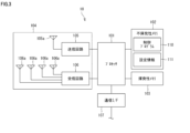
- the infrastructure radio wave sensor 10 includes a processor 101, a non-volatile memory 102, a volatile memory 103, a transmitting/receiving unit 104, and a communication interface (communication I/F) 107.
- the processor 101 is, for example, a CPU (Central Processing Unit). However, the processor 101 is not limited to a CPU.
- the processor 101 may be a GPU (Graphics Processing Unit).
- the processor 101 may be, for example, an ASIC (Application Specific Integrated Circuit), or a programmable logic device such as a gate array or FPGA (Field Programmable Gate Array). In this case, the ASIC or programmable logic device is configured to be capable of executing the same processing as the control program 110.
- ASIC Application Specific Integrated Circuit
- FPGA Field Programmable Gate Array
- the transceiver unit 104 includes a transmission circuit 105 and a reception circuit 106.
- the volatile memory 203 is, for example, a semiconductor memory such as an SRAM or a DRAM.
- the non-volatile memory 202 is, for example, a flash memory, a hard disk, a ROM, etc.
- the non-volatile memory 202 stores a setting program 210, which is a computer program, and data used to execute the setting program 210.
- Each function of the setting device 200 is realized by the processor 201 executing the setting program 210.
- the setting program 210 can be stored in a recording medium such as a flash memory, a ROM, or a CD-ROM.
- the processor 201 determines the detection area 30 of the infrastructure radio wave sensor 10 using the setting program 210.
- the processor 201 is, for example, a CPU. However, the processor 201 is not limited to a CPU.
- the processor 201 may be a GPU.
- the processor 201 may be, for example, an ASIC, or a programmable logic device such as a gate array or FPGA. In this case, the ASIC or programmable logic device is configured to be able to execute the same processing as the setting program 210.
- the communication I/F 206 can communicate with an external device.
- the communication I/F 206 is connected to the infrastructure radio wave sensor 10 by a communication cable and can communicate with the infrastructure radio wave sensor 10.
- the communication I/F 206 is a wireless communication interface and may be able to communicate with the infrastructure radio wave sensor 10 wirelessly.
- the communication I/F 206 may be able to communicate with the infrastructure radio wave sensor 10 via a wide area communication network.
- the detection unit 121 detects the position and speed of an object based on the reflected waves that are generated when radio waves are irradiated onto the object and reflected by the object.
- the tracking unit 122 tracks the detected objects. Specifically, the tracking unit 122 assigns an ID to each object detected by the detection unit 121. The detection unit 121 outputs the detection results of the object's position and speed at regular time intervals. The tracking unit 122 identifies the currently detected objects that are the same as the previously detected object. For example, the tracking unit 122 estimates the current position of object a based on the previous movement direction and speed of object a. Among the currently detected objects, the tracking unit 122 identifies the object closest to the position estimated from the previous movement direction and speed of object a as object a. An object identified as the same as the previously detected object inherits the ID of the previously detected object.
- the acquisition unit 221 acquires the object detection results output from the infrastructure radio wave sensor 10.
- the acquisition unit 221 acquires the detection results at regular time intervals.
- the acquisition unit 221 accumulates the acquired detection results of the object. Specifically, the acquisition unit 221 registers the acquired detection results in a database (not shown) provided in the non-volatile memory 102. In this way, the detection results are accumulated in the database.
- the generating unit 222 generates a movement trajectory of the object in the unique coordinate space based on the detection results acquired by the acquiring unit 221.
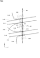
- the movement trajectory 321A of a moving pedestrian may include the movement trajectories 320A, 320B of a waiting pedestrian.
- the generation unit 222 can separate the movement trajectories 320A, 320B of the waiting pedestrian from the movement trajectory 321A of a passing pedestrian based on the detected position of an object included in the movement trajectory.
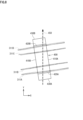
- Vehicle movement trajectories 311A, 311B, 311C, 311D, 312A, 312B, 312C, 312D include movement trajectories 311A, 311B, 311C, 311D of vehicles going straight through intersection 70, and movement trajectories 312A, 312B, 312C, 312D of vehicles turning right or left at the intersection.
- Movement trajectory 311A is the movement trajectory of a vehicle traveling straight through the intersection 70 in the x1 direction in the incoming lane 61a.
- Movement trajectory 311B is the movement trajectory of a vehicle traveling straight through the intersection 70 in the x1 direction in the incoming lane 61b.
- Movement trajectory 311C is the movement trajectory of a vehicle traveling straight through the intersection 70 in the x2 direction in the outgoing lane 62a.
- Movement trajectory 311D is the movement trajectory of a vehicle traveling straight through the intersection 70 in the x2 direction in the outgoing lane 62b.
- the identification unit 223 identifies a movement trajectory 312A of a vehicle in group B2 that travels on the roadway 65 in the y1 direction and turns left at the intersection 70 to enter the exit lane 62a.
- the identification unit 223 identifies a movement trajectory 312B of a vehicle that travels on the roadway 65 in the y2 direction and turns right at the intersection 70 to enter the exit lane 62b.
- the identification unit 223 identifies a movement trajectory 312C of a vehicle that travels on the entrance lane 61b in the x1 direction and turns right at the intersection 70 to enter the roadway 65.
- the identification unit 223 identifies the movement trajectory of the pedestrian waiting to cross the crosswalk. Specifically, the identification unit 223 identifies a movement trajectory with an indefinite movement direction (i.e., a movement trajectory with little movement or with a movement direction that changes frequently). For example, the identification unit 223 identifies the movement trajectory of an object that exists for a certain period of time in a certain area (the area around both ends of the movement trajectory 321A). In this way, the movement trajectories 320A and 320B are identified.
- group C the group of the movement trajectories 320A and 320B is referred to as "group C".
- the determination unit 224 may determine the median strip area as a sub-area of the detection area 400 based on the movement trajectory of the vehicle traveling on the roadway 60.
- the transmitting circuit 105 generates a modulated wave and transmits the generated modulated wave from the transmitting antenna 105a.
- the transmitted modulated wave hits an object (pedestrian, bicycle, vehicle), and the reflected wave from the object is received by the receiving antenna 106a.
- the receiving circuit 106 processes the reflected wave signal and generates reflected wave data.
- the processor 101 accepts the reflected wave data (step S101).
- the processor 101 outputs the detection result including the object's position, speed, and ID (step S104), and returns to step S101.
- the infrastructure radio wave sensor 10 outputs the detection result at regular intervals.
- the processor 201 generates a movement trajectory of the object from the detection results obtained from the infrastructure radio wave sensor 10 (step S202).
- the processor 201 identifies each of the groups A, B1, B2, and C from the multiple movement trajectories generated (step S203).
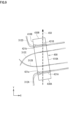
- the processor 201 provisionally determines the third definition line 430A, the fourth definition line 430B, and the first boundary line 420A and the second boundary line 420B of the detection area 400 based on the group B1 (step S205).
- the processor 201 determines the shapes of the first boundary line 421A and the second boundary line 421B based on group B2 (step S206).
- the processor 201 determines the positions of the third boundary line 440A and the fourth boundary line 440B based on the group B1 (step S208).
- the processor 201 superimposes and displays the determined detection area 400 and the object's movement path on the display device 212 (step S209).
- the user compares the position and shape of the displayed detection area 400 with the position and shape of the movement path, and determines whether the detection area 400 is appropriate. If the detection area 400 is appropriate, the user inputs approval of the detection area 400 to the setting device 200 via the input device 211, and if the detection area 400 is not appropriate, the user inputs rejection of the detection area 400 to the setting device 200 via the input device 211 (step S210).
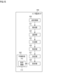
- the infrastructure radio wave sensor 10A has the functions of a generating unit 125, an identifying unit 126, a determining unit 127, and a setting unit 128 in addition to a detecting unit 121 and a tracking unit 122.
- the generation unit 125 generates a movement trajectory of an object based on the detection result of the object to which an ID has been assigned by the tracking unit 122.
- the detailed functions of the generation unit 125 are the same as those of the generation unit 222, so a description thereof will be omitted.
- the identification unit 126 identifies each of the groups A, B1, B2, and C from the movement trajectories generated by the generation unit 125.
- the detailed functions of the identification unit 126 are the same as those of the identification unit 223, and therefore will not be described.
Landscapes
- Engineering & Computer Science (AREA)
- Radar, Positioning & Navigation (AREA)
- Remote Sensing (AREA)
- Physics & Mathematics (AREA)
- General Physics & Mathematics (AREA)
- Electromagnetism (AREA)
- Computer Networks & Wireless Communication (AREA)
- Traffic Control Systems (AREA)
Abstract
Description
交差点では、2つの車道の接続箇所に隅切りが設けられることがある。したがって、車道に重複する横断歩道エリアと、歩道に重複する待機エリアとの境界線が直線状であるとは限らない。電波センサの検知エリアにおいて、横断歩道エリアと待機エリアとの境界線を正確に決定しなければ、横断歩道を通行する歩行者と、待機エリアで待機する歩行者とを正確に識別することができない。
本開示によれば、電波センサの検知エリアにおける横断歩道エリアと待機エリアとの境界線を正しく決定することができる。
以下、本開示の実施形態の概要を列記して説明する。
以下、図面を参照しつつ、本開示の実施形態の詳細を説明する。なお、以下に記載する実施形態の少なくとも一部を任意に組み合わせてもよい。
図1が参照される。電波センサの一例としての本実施形態に係るインフラ電波センサ10は、交通監視用の電波レーダである。インフラ電波センサ10は、横断歩道20における物体(歩行者、自転車、車両)を検知する。インフラ電波センサ10は、例えばミリ波レーダである。
図3が参照される。インフラ電波センサ10は、プロセッサ101と、不揮発性メモリ102と、揮発性メモリ103と、送受信部104と、通信インタフェース(通信I/F)107とを含む。
図4は、実施形態に係る設定装置のハードウェア構成の一例を示すブロック図である。本実施形態に係る設定装置200は、インフラ電波センサ10の検知エリア30の設定に用いられる。設定装置200は、プロセッサ201と、不揮発性メモリ202と、揮発性メモリ203と、入出力インタフェース(I/O)204と、グラフィックコントローラ205と、通信インタフェース(通信I/F)206とを含む。設定装置200は、入力装置211と、表示装置212とをさらに含む。なお、入力装置211及び表示装置212の少なくとも1つは、設定装置200に接続された外部装置であってもよい。
図5が参照される。プロセッサ101が制御プログラム110を実行することにより、インフラ電波センサ10は、検知部121と、追跡部122と、出力部123と、入力部124として機能する。プロセッサ201が設定プログラム210を実行することにより、設定装置200は、取得部221と、生成部222と、特定部223と、決定部224と、表示制御部225と、設定部226として機能する。
以下、インフラ電波センサ10に検知エリアを設定するためのインフラ電波センサ10及び設定装置200の動作について説明する。
設定装置200の検知エリアを決定するための各機能をインフラ電波センサに設けてもよい。図15は、実施形態に係るインフラ電波センサの機能の1つの変形例を示す機能ブロック図である。
20 横断歩道
30,400 検知エリア
31,401 ゼブラエリア
32a,32b,402A,402B 待機エリア
33a,33b 境界線
40 電波照射範囲
50 構造物
51 ポール
52 アーム
63a,63b 歩道
60,65 車道
61a,61b 流入車線
62a,62b 流出車線
61c,62c 隅切り
70 交差点
101 プロセッサ
102 不揮発性メモリ
103 揮発性メモリ
104 送受信部
105 送信回路
106 受信回路
105a 送信アンテナ
106a 受信アンテナ
107 通信インタフェース(通信I/F)
110 制御プログラム
111 設定情報
121 検知部
122 追跡部
123 出力部
124 入力部
200 設定装置
201 プロセッサ
202 不揮発性メモリ
203 揮発性メモリ
204 入出力インタフェース(I/O)
205 グラフィックコントローラ
206 通信インタフェース(通信I/F)
210 設定プログラム
211 入力装置
212 表示装置
221 取得部
222,125 生成部
223,126 特定部
224,127 決定部
225 表示制御部
226,128 設定部
311A,311B,311C,311D,312A,312B,312C,312D,320A,320B,321A 移動軌跡
450 電波照射方向
401A 第1ゼブラエリア
401B 第2ゼブラエリア
410A 第1定義線
410B 第2定義線
420A,421A,422A 第1境界線
420B,421B,422B 第2境界線
421a,421b 傾斜部分
430A,431A 第3定義線
430B,431B 第4定義線
440 中央分離帯エリア
440A 第3境界線
440B 第4境界線
500 確認画面
Claims (15)
- 横断歩道を移動する物体を電波センサにより検知した検知結果を取得する取得部と、
前記検知結果に基づいて、前記電波センサに予め設定された座標空間における前記物体の移動軌跡を生成する生成部と、
前記物体の移動軌跡に基づいて、前記座標空間において前記横断歩道に対応する検知エリアを決定する決定部と、
を備え、
前記検知エリアは、前記横断歩道を含む第1エリアを含み、
前記決定部は、前記横断歩道と一部において重なる第1車道を走行する車両の移動軌跡に基づいて、前記第1エリアと通行者が前記横断歩道の通行を待機するための第2エリアとの境界線を決定する、
電波センサの設定装置。 - 前記検知エリアは、さらに前記第2エリアを含む、
請求項1に記載の電波センサの設定装置。 - 前記決定部は、前記第1車道と、前記第1車道に交差する第2車道との交差点において右折又は左折する車両の移動軌跡に基づいて、前記境界線を決定する、
請求項1または請求項2に記載の電波センサの設定装置。 - 前記決定部は、前記交差点において右折又は左折する車両の移動軌跡に基づいて、前記境界線の形状を決定する、
請求項3に記載の電波センサの設定装置。 - 前記検知エリアは、前記第2エリアとして、前記第1車道において前記交差点へ車両が流入する流入車線に接する第1待機エリアと、前記第1車道において前記交差点から車両が流出する流出車線に接する第2待機エリアとを含み、
前記決定部は、
前記流入車線を左折又は右折して前記第2車道へ進入する車両の移動軌跡である第1移動軌跡に基づいて、前記第1エリアと前記第1待機エリアとの境界線である第1境界線を決定し、
前記第2車道を左折又は右折して前記流出車線へ進入する車両の移動軌跡である第2移動軌跡に基づいて、前記第1エリアと前記第2待機エリアとの境界線である第2境界線を決定する、
請求項3または請求項4に記載の電波センサの設定装置。 - 前記決定部は、前記横断歩道の通行を待機する通行者の前記電波センサによる検知位置にさらに基づいて、前記境界線を決定する、
請求項1から請求項5のいずれか1項に記載の電波センサの設定装置。 - 前記取得部が前記電波センサから取得した複数の前記検知結果に基づいて、移動方向が不定の物体を特定する特定部をさらに備え、
前記決定部は、前記特定部によって特定された前記物体の位置に基づいて、前記境界線を決定する、
請求項6に記載の電波センサの設定装置。 - 前記決定部は、前記特定部によって特定された前記物体の位置に基づいて、前記境界線の位置を決定する、
請求項7に記載の電波センサの設定装置。 - 前記設定装置は、前記決定部によって決定された境界線と、前記生成部によって生成された前記物体の移動軌跡とを表示装置に表示させる表示制御部をさらに備える、
請求項1から請求項8のいずれか1項に記載の電波センサの設定装置。 - 電波センサであって、
横断歩道を含むエリアへ電波を送信し、物体による前記電波の反射波を受信する送受信部と、
前記送受信部によって受信された前記反射波に基づいて、横断歩道を移動する物体の位置を検知する検知部と、
前記物体の位置に基づいて、前記電波センサに予め設定された座標空間における前記物体の移動軌跡を生成する生成部と、
前記物体の移動軌跡に基づいて、前記座標空間において前記横断歩道に対応する検知エリアを決定する決定部と、
を備え、
前記検知エリアは、前記横断歩道を含む第1エリアを含み、
前記決定部は、前記横断歩道と一部において重なる第1車道を走行する車両の移動軌跡に基づいて、前記第1エリアと通行者が前記横断歩道の通行を待機するための第2エリアとの境界線を決定する、
電波センサ。 - 前記検知エリアは、さらに前記第2エリアを含む、
請求項10に記載の電波センサ。 - 横断歩道を移動する物体の電波センサによる検知結果を取得するステップと、
前記検知結果に基づいて、前記電波センサに予め設定された座標空間における前記物体の移動軌跡を生成するステップと、
前記物体の移動軌跡に基づいて、前記座標空間において前記横断歩道に対応する検知エリアを決定するステップと、
を含み、
前記検知エリアは、前記横断歩道を含む第1エリアを含み、
前記決定するステップは、前記横断歩道と一部において重なる第1車道を走行する車両の移動軌跡に基づいて、前記第1エリアと通行者が前記横断歩道の通行を待機するための第2エリアとの境界線を決定することを含む、
電波センサの設定方法。 - 前記検知エリアは、さらに前記第2エリアを含む、
請求項12に記載の電波センサの設定方法。 - 横断歩道上の物体を検知する電波センサを設定するためのコンピュータプログラムであって、
コンピュータに、
横断歩道を移動する物体の電波センサによる検知結果を取得するステップと、
前記検知結果に基づいて、前記電波センサに予め設定された座標空間における前記物体の移動軌跡を生成するステップと、
前記物体の移動軌跡に基づいて、前記座標空間において前記横断歩道に対応する検知エリアを決定するステップと、を実行させ、
前記検知エリアは、前記横断歩道を含む第1エリアを含み、
前記決定するステップは、前記横断歩道と一部において重なる第1車道を走行する車両の移動軌跡に基づいて、前記第1エリアと通行者が前記横断歩道の通行を待機するための第2エリアとの境界線を決定することを含む、
コンピュータプログラム。 - 前記検知エリアは、さらに前記第2エリアを含む、
請求項14に記載のコンピュータプログラム。
Priority Applications (1)
| Application Number | Priority Date | Filing Date | Title |
|---|---|---|---|
| JP2024568701A JPWO2024147237A1 (ja) | 2023-01-06 | 2023-11-24 |
Applications Claiming Priority (2)
| Application Number | Priority Date | Filing Date | Title |
|---|---|---|---|
| JP2023000968 | 2023-01-06 | ||
| JP2023-000968 | 2023-01-06 |
Publications (1)
| Publication Number | Publication Date |
|---|---|
| WO2024147237A1 true WO2024147237A1 (ja) | 2024-07-11 |
Family
ID=91803825
Family Applications (1)
| Application Number | Title | Priority Date | Filing Date |
|---|---|---|---|
| PCT/JP2023/042105 Ceased WO2024147237A1 (ja) | 2023-01-06 | 2023-11-24 | 電波センサの設定装置、電波センサ、電波センサの設定方法、及びコンピュータプログラム |
Country Status (2)
| Country | Link |
|---|---|
| JP (1) | JPWO2024147237A1 (ja) |
| WO (1) | WO2024147237A1 (ja) |
Citations (2)
| Publication number | Priority date | Publication date | Assignee | Title |
|---|---|---|---|---|
| JP2017090078A (ja) * | 2015-11-04 | 2017-05-25 | 住友電気工業株式会社 | 電波センサ、検知方法および検知プログラム |
| JP2020087191A (ja) * | 2018-11-29 | 2020-06-04 | 株式会社Soken | 車線境界設定装置、車線境界設定方法 |
-
2023
- 2023-11-24 WO PCT/JP2023/042105 patent/WO2024147237A1/ja not_active Ceased
- 2023-11-24 JP JP2024568701A patent/JPWO2024147237A1/ja active Pending
Patent Citations (2)
| Publication number | Priority date | Publication date | Assignee | Title |
|---|---|---|---|---|
| JP2017090078A (ja) * | 2015-11-04 | 2017-05-25 | 住友電気工業株式会社 | 電波センサ、検知方法および検知プログラム |
| JP2020087191A (ja) * | 2018-11-29 | 2020-06-04 | 株式会社Soken | 車線境界設定装置、車線境界設定方法 |
Also Published As
| Publication number | Publication date |
|---|---|
| JPWO2024147237A1 (ja) | 2024-07-11 |
Similar Documents
| Publication | Publication Date | Title |
|---|---|---|
| US11703335B2 (en) | Coordinating and learning maps dynamically | |
| US11592566B2 (en) | Vehicle systems and methods utilizing LIDAR data for road condition estimation | |
| JP4345832B2 (ja) | 道路状況検出システム | |
| US20200250439A1 (en) | Automated Road Edge Boundary Detection | |
| RU2629433C2 (ru) | Устройство обнаружения трехмерных объектов | |
| EP2674778B1 (en) | Monitoring device, monitoring method and program | |
| JP4086298B2 (ja) | 物体検出方法及び装置 | |
| JP5868586B2 (ja) | ビデオ画像に基づく道路特性分析、車線検出、および車線逸脱防止方法および装置 | |
| JP2005222538A (ja) | 車道上のマークの認識方法 | |
| US20230065727A1 (en) | Vehicle and vehicle control method | |
| WO2023135985A1 (ja) | 電波センサの設置支援装置、コンピュータプログラム、及び電波センサの設置位置決定方法 | |
| JPH0844999A (ja) | 接近予測装置 | |
| JP3786113B2 (ja) | 接近予測装置 | |
| JP7815771B2 (ja) | 電波センサの設置支援装置、コンピュータプログラム、電波センサの設置位置決定方法、及び電波センサの設置支援方法 | |
| WO2024147237A1 (ja) | 電波センサの設定装置、電波センサ、電波センサの設定方法、及びコンピュータプログラム | |
| KR102622937B1 (ko) | 보행자 사고 예방 시스템 및 방법 | |
| JP4230373B2 (ja) | 検知装置及び検知方法 | |
| JP4279302B2 (ja) | 検知装置 | |
| JP3607841B2 (ja) | 障害物検出装置 | |
| JP4365282B2 (ja) | 障害物検出システム及び障害物検出方法 | |
| WO2026028665A1 (ja) | 電波センサの設定支援装置、電波センサの設定支援方法、及びコンピュータプログラム | |
| WO2026053775A1 (ja) | 電波センサ、電波センサの設定支援方法、及びコンピュータプログラム | |
| JP7811092B2 (ja) | 検知装置 | |
| EP1038189A1 (en) | Method for predicting the existence of a curve in a road portion | |
| WO2025258444A1 (ja) | 設定支援装置、電波センサ、設定支援方法、及び設定支援プログラム |
Legal Events
| Date | Code | Title | Description |
|---|---|---|---|
| 121 | Ep: the epo has been informed by wipo that ep was designated in this application |
Ref document number: 23914725 Country of ref document: EP Kind code of ref document: A1 |
|
| ENP | Entry into the national phase |
Ref document number: 2024568701 Country of ref document: JP Kind code of ref document: A |
|
| WWE | Wipo information: entry into national phase |
Ref document number: 2024568701 Country of ref document: JP |
|
| NENP | Non-entry into the national phase |
Ref country code: DE |
|
| 122 | Ep: pct application non-entry in european phase |
Ref document number: 23914725 Country of ref document: EP Kind code of ref document: A1 |