WO2024143512A1 - 電気化学セル、電気化学セル装置、モジュールおよびモジュール収容装置 - Google Patents
電気化学セル、電気化学セル装置、モジュールおよびモジュール収容装置 Download PDFInfo
- Publication number
- WO2024143512A1 WO2024143512A1 PCT/JP2023/047119 JP2023047119W WO2024143512A1 WO 2024143512 A1 WO2024143512 A1 WO 2024143512A1 JP 2023047119 W JP2023047119 W JP 2023047119W WO 2024143512 A1 WO2024143512 A1 WO 2024143512A1
- Authority
- WO
- WIPO (PCT)
- Prior art keywords
- solid electrolyte
- electrochemical cell
- electrolyte layer
- module
- metal plate
- Prior art date
- Legal status (The legal status is an assumption and is not a legal conclusion. Google has not performed a legal analysis and makes no representation as to the accuracy of the status listed.)
- Ceased
Links
Images




Classifications
-
- H—ELECTRICITY
- H01—ELECTRIC ELEMENTS
- H01M—PROCESSES OR MEANS, e.g. BATTERIES, FOR THE DIRECT CONVERSION OF CHEMICAL ENERGY INTO ELECTRICAL ENERGY
- H01M8/00—Fuel cells; Manufacture thereof
- H01M8/24—Grouping of fuel cells, e.g. stacking of fuel cells
- H01M8/2465—Details of groupings of fuel cells
- H01M8/247—Arrangements for tightening a stack, for accommodation of a stack in a tank or for assembling different tanks
- H01M8/2475—Enclosures, casings or containers of fuel cell stacks
-
- C—CHEMISTRY; METALLURGY
- C25—ELECTROLYTIC OR ELECTROPHORETIC PROCESSES; APPARATUS THEREFOR
- C25B—ELECTROLYTIC OR ELECTROPHORETIC PROCESSES FOR THE PRODUCTION OF COMPOUNDS OR NON-METALS; APPARATUS THEREFOR
- C25B1/00—Electrolytic production of inorganic compounds or non-metals
- C25B1/01—Products
- C25B1/02—Hydrogen or oxygen
- C25B1/04—Hydrogen or oxygen by electrolysis of water
- C25B1/042—Hydrogen or oxygen by electrolysis of water by electrolysis of steam
-
- C—CHEMISTRY; METALLURGY
- C25—ELECTROLYTIC OR ELECTROPHORETIC PROCESSES; APPARATUS THEREFOR
- C25B—ELECTROLYTIC OR ELECTROPHORETIC PROCESSES FOR THE PRODUCTION OF COMPOUNDS OR NON-METALS; APPARATUS THEREFOR
- C25B13/00—Diaphragms; Spacing elements
- C25B13/04—Diaphragms; Spacing elements characterised by the material
- C25B13/05—Diaphragms; Spacing elements characterised by the material based on inorganic materials
- C25B13/07—Diaphragms; Spacing elements characterised by the material based on inorganic materials based on ceramics
-
- C—CHEMISTRY; METALLURGY
- C25—ELECTROLYTIC OR ELECTROPHORETIC PROCESSES; APPARATUS THEREFOR
- C25B—ELECTROLYTIC OR ELECTROPHORETIC PROCESSES FOR THE PRODUCTION OF COMPOUNDS OR NON-METALS; APPARATUS THEREFOR
- C25B9/00—Cells or assemblies of cells; Constructional parts of cells; Assemblies of constructional parts, e.g. electrode-diaphragm assemblies; Process-related cell features
- C25B9/17—Cells comprising dimensionally-stable non-movable electrodes; Assemblies of constructional parts thereof
- C25B9/19—Cells comprising dimensionally-stable non-movable electrodes; Assemblies of constructional parts thereof with diaphragms
- C25B9/23—Cells comprising dimensionally-stable non-movable electrodes; Assemblies of constructional parts thereof with diaphragms comprising ion-exchange membranes in or on which electrode material is embedded
-
- C—CHEMISTRY; METALLURGY
- C25—ELECTROLYTIC OR ELECTROPHORETIC PROCESSES; APPARATUS THEREFOR
- C25B—ELECTROLYTIC OR ELECTROPHORETIC PROCESSES FOR THE PRODUCTION OF COMPOUNDS OR NON-METALS; APPARATUS THEREFOR
- C25B9/00—Cells or assemblies of cells; Constructional parts of cells; Assemblies of constructional parts, e.g. electrode-diaphragm assemblies; Process-related cell features
- C25B9/60—Constructional parts of cells
-
- C—CHEMISTRY; METALLURGY
- C25—ELECTROLYTIC OR ELECTROPHORETIC PROCESSES; APPARATUS THEREFOR
- C25B—ELECTROLYTIC OR ELECTROPHORETIC PROCESSES FOR THE PRODUCTION OF COMPOUNDS OR NON-METALS; APPARATUS THEREFOR
- C25B9/00—Cells or assemblies of cells; Constructional parts of cells; Assemblies of constructional parts, e.g. electrode-diaphragm assemblies; Process-related cell features
- C25B9/60—Constructional parts of cells
- C25B9/65—Means for supplying current; Electrode connections; Electric inter-cell connections
-
- C—CHEMISTRY; METALLURGY
- C25—ELECTROLYTIC OR ELECTROPHORETIC PROCESSES; APPARATUS THEREFOR
- C25B—ELECTROLYTIC OR ELECTROPHORETIC PROCESSES FOR THE PRODUCTION OF COMPOUNDS OR NON-METALS; APPARATUS THEREFOR
- C25B9/00—Cells or assemblies of cells; Constructional parts of cells; Assemblies of constructional parts, e.g. electrode-diaphragm assemblies; Process-related cell features
- C25B9/70—Assemblies comprising two or more cells
- C25B9/73—Assemblies comprising two or more cells of the filter-press type
- C25B9/77—Assemblies comprising two or more cells of the filter-press type having diaphragms
-
- H—ELECTRICITY
- H01—ELECTRIC ELEMENTS
- H01M—PROCESSES OR MEANS, e.g. BATTERIES, FOR THE DIRECT CONVERSION OF CHEMICAL ENERGY INTO ELECTRICAL ENERGY
- H01M8/00—Fuel cells; Manufacture thereof
- H01M8/02—Details
- H01M8/0202—Collectors; Separators, e.g. bipolar separators; Interconnectors
- H01M8/0204—Non-porous and characterised by the material
- H01M8/0206—Metals or alloys
-
- H—ELECTRICITY
- H01—ELECTRIC ELEMENTS
- H01M—PROCESSES OR MEANS, e.g. BATTERIES, FOR THE DIRECT CONVERSION OF CHEMICAL ENERGY INTO ELECTRICAL ENERGY
- H01M8/00—Fuel cells; Manufacture thereof
- H01M8/02—Details
- H01M8/0202—Collectors; Separators, e.g. bipolar separators; Interconnectors
- H01M8/0258—Collectors; Separators, e.g. bipolar separators; Interconnectors characterised by the configuration of channels, e.g. by the flow field of the reactant or coolant
-
- H—ELECTRICITY
- H01—ELECTRIC ELEMENTS
- H01M—PROCESSES OR MEANS, e.g. BATTERIES, FOR THE DIRECT CONVERSION OF CHEMICAL ENERGY INTO ELECTRICAL ENERGY
- H01M8/00—Fuel cells; Manufacture thereof
- H01M8/02—Details
- H01M8/0271—Sealing or supporting means around electrodes, matrices or membranes
- H01M8/0273—Sealing or supporting means around electrodes, matrices or membranes with sealing or supporting means in the form of a frame
-
- H—ELECTRICITY
- H01—ELECTRIC ELEMENTS
- H01M—PROCESSES OR MEANS, e.g. BATTERIES, FOR THE DIRECT CONVERSION OF CHEMICAL ENERGY INTO ELECTRICAL ENERGY
- H01M8/00—Fuel cells; Manufacture thereof
- H01M8/24—Grouping of fuel cells, e.g. stacking of fuel cells
- H01M8/241—Grouping of fuel cells, e.g. stacking of fuel cells with solid or matrix-supported electrolytes
- H01M8/2425—High-temperature cells with solid electrolytes
- H01M8/2432—Grouping of unit cells of planar configuration
-
- H—ELECTRICITY
- H01—ELECTRIC ELEMENTS
- H01M—PROCESSES OR MEANS, e.g. BATTERIES, FOR THE DIRECT CONVERSION OF CHEMICAL ENERGY INTO ELECTRICAL ENERGY
- H01M8/00—Fuel cells; Manufacture thereof
- H01M8/10—Fuel cells with solid electrolytes
- H01M8/12—Fuel cells with solid electrolytes operating at high temperature, e.g. with stabilised ZrO2 electrolyte
- H01M2008/1293—Fuel cells with solid oxide electrolytes
-
- Y—GENERAL TAGGING OF NEW TECHNOLOGICAL DEVELOPMENTS; GENERAL TAGGING OF CROSS-SECTIONAL TECHNOLOGIES SPANNING OVER SEVERAL SECTIONS OF THE IPC; TECHNICAL SUBJECTS COVERED BY FORMER USPC CROSS-REFERENCE ART COLLECTIONS [XRACs] AND DIGESTS
- Y02—TECHNOLOGIES OR APPLICATIONS FOR MITIGATION OR ADAPTATION AGAINST CLIMATE CHANGE
- Y02E—REDUCTION OF GREENHOUSE GAS [GHG] EMISSIONS, RELATED TO ENERGY GENERATION, TRANSMISSION OR DISTRIBUTION
- Y02E60/00—Enabling technologies; Technologies with a potential or indirect contribution to GHG emissions mitigation
- Y02E60/30—Hydrogen technology
- Y02E60/50—Fuel cells
Definitions
- This disclosure relates to electrochemical cells, electrochemical cell devices, modules, and module housing devices.
- a fuel cell is a type of electrochemical cell that can generate electricity using a fuel gas such as a hydrogen-containing gas and an oxygen-containing gas such as air.
- the electrochemical cell includes a metal plate and an element portion.
- the metal plate has a first surface and a second surface located opposite the first surface.
- the element portion is located on the first surface and has a first electrode layer, a solid electrolyte layer, and a second electrode layer.
- the metal plate has a first portion that allows gas to flow between the first surface and the second surface, and a second portion located around the first portion.
- the solid electrolyte layer is located so as to overlap the first portion in a plan view.
- the electrochemical cell includes a metal plate and an element portion.
- the metal plate has a first surface and a second surface located opposite the first surface.
- the element portion is located on the first surface and has a first electrode layer, a solid electrolyte layer, and a second electrode layer.
- the metal plate has a first portion that allows gas to flow between the first surface and the second surface, and a second portion located around the first portion.
- the outline of the first portion in a planar view is located inside the outline of the solid electrolyte layer in a planar view.
- the module housing device of the present disclosure also includes the module described above, ancillary equipment for operating the module, and an exterior case that houses the module and the auxiliaries.
- FIG. 1A is a cross-sectional view illustrating an example of an electrochemical cell according to a first embodiment.
- FIG. 1B is a side view of an example of the electrochemical cell according to the first embodiment, as viewed from the air electrode side.
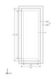
- FIG. 2 is a plan view showing an example of the arrangement of the solid electrolyte layer and the metal plate of the electrochemical cell according to the first embodiment.
- FIG. 3A is a plan view illustrating an example of the first portion.
- FIG. 3B is a plan view showing another example of the first portion.
- FIG. 4 is a plan view showing another example of the arrangement of the solid electrolyte layer and the metal plate of the electrochemical cell according to the first embodiment.
- FIG. 1A is a cross-sectional view illustrating an example of an electrochemical cell according to a first embodiment.
- FIG. 1B is a side view of an example of the electrochemical cell according to the first embodiment, as viewed from the air electrode side.
- FIG. 2 is a plan view showing
- FIG. 5A is a perspective view showing an example of an electrochemical cell device according to the first embodiment.
- FIG. 5B is a cross-sectional view taken along line XX shown in FIG. 5A.
- FIG. 5C is a top view illustrating an example of the electrochemical cell device according to the first embodiment.
- FIG. 6 is an external perspective view illustrating an example of a module according to the first embodiment.
- FIG. 7 is an exploded perspective view illustrating an example of a module housing device according to the first embodiment.
- FIG. 8 is a cross-sectional view illustrating an example of an electrochemical cell according to the second embodiment.
- FIG. 9 is a plan view showing an example of the arrangement of the solid electrolyte layer and the metal plate of the electrochemical cell according to the second embodiment.
- FIG. 10 is a plan view showing another example of the arrangement of the solid electrolyte layer and the metal plate of the electrochemical cell according to the second embodiment.
- the above-mentioned fuel cell stack device had room for improvement in terms of durability.
- the electrochemical cell device may include a cell stack having a plurality of electrochemical cells.
- An electrochemical cell device having a plurality of electrochemical cells will be simply referred to as a cell stack device.
- FIG. 1A is a cross-sectional view showing an example of an electrochemical cell according to the first embodiment.
- FIG. 1B is a side view of an example of an electrochemical cell according to the first embodiment, viewed from the air electrode side. Note that FIGS. 1A and 1B show enlarged views of parts of each component of the electrochemical cell.
- the electrochemical cell may also be simply referred to as a cell.
- the cell 1 has an element section 3 in which a fuel electrode layer 5, which is a first electrode layer, a solid electrolyte layer 6, and an air electrode layer 8, which is a second electrode layer, are stacked, and a metal plate 2.
- the metal plate 2 is a plate-shaped member made of a metal containing chromium.
- the metal plate 2 is also electrically conductive.
- the metal plate 2 may be, for example, a stainless steel with high heat resistance, such as ferritic stainless steel or austenitic stainless steel.
- the metal plate 2 may be, for example, a nickel-chromium alloy or an iron-chromium alloy.
- the metal plate 2 may contain, for example, a metal oxide.
- the metal plate 2 may be, for example, composed of one or more members.
- the metal plate 2 electrically connects the cells 1 adjacent to each other in the X-axis direction.
- the metal plate 2 has a first surface n1 and a second surface n2 located on the opposite side of the first surface n1.
- the metal plate 2 is a support that supports the element portion 3, and the element portion 3 is located on the first surface n1 side.
- the second surface n2 side has a gas flow path 2a that extends in the Z-axis direction and a member 32 located outside the gas flow path 2a.
- the metal plate 2 has a first portion 201 and a second portion 202.
- the first portion 201 is positioned so as to face the element portion 3.
- the first portion 201 has, for example, a plurality of openings 2b (see Figures 3A and 3B) penetrating in the X-axis direction, and is a portion through which gas can flow between the first surface n1 and the second surface n2.
- the second portion 202 is positioned around the first portion 201, and is an airtight portion that does not allow gas to flow between the first surface n1 and the second surface n2.
- the element portion 3 is located on the first surface n1 of the metal plate 2.
- the element portion 3 has a fuel electrode layer 5, a solid electrolyte layer 6, and an air electrode layer 8.
- the fuel electrode layer 5 is the first electrode layer that comes into contact with the fuel gas, which is a reducing gas.
- the fuel electrode layer 5 has gas permeability.
- the open porosity of the fuel electrode layer 5 may be, for example, in the range of 30% to 50%, particularly 35% to 45%.
- the open porosity of the fuel electrode layer 5 may also be referred to as the porosity or void ratio of the fuel electrode layer 5.
- the material of the fuel electrode layer 5 may be a generally known material.
- the fuel electrode layer 5 may be made of a porous conductive ceramic, such as a ceramic containing calcium oxide, magnesium oxide, or ZrO 2 in which a rare earth element oxide is dissolved, and Ni and/or NiO.
- the rare earth element oxide may contain a plurality of rare earth elements selected from Sc, Y, La, Nd, Sm, Gd, Dy, and Yb. Calcium oxide, magnesium oxide, or ZrO 2 in which a rare earth element oxide is dissolved may be referred to as stabilized zirconia.
- the stabilized zirconia may include partially stabilized zirconia.
- the solid electrolyte layer 6 is an electrolyte and transfers ions between the fuel electrode layer 5 and the air electrode layer 8. At the same time, the solid electrolyte layer 6 has gas barrier properties, making it difficult for leakage of fuel gas and oxygen-containing gas to occur.
- the material of the solid electrolyte layer 6 may be, for example, ZrO 2 in which 3 mol % to 15 mol % of a rare earth element oxide is dissolved.
- the rare earth element oxide may include, for example, one or more rare earth elements selected from Sc, Y, La, Nd, Sm, Gd, Dy, and Yb.
- the solid electrolyte layer 6 may include, for example, ZrO 2 in which Yb, Sc, or Gd is dissolved, CeO 2 in which La, Nd, or Yb is dissolved, BaZrO 3 in which Sc or Yb is dissolved, or BaCeO 3 in which Sc or Yb is dissolved.
- the air electrode layer 8 is a second electrode layer that is in contact with the oxygen-containing gas.
- the air electrode layer 8 has gas permeability.
- the open porosity of the air electrode layer 8 may be in the range of, for example, 20% to 50%, particularly 30% to 50%.
- the material of the air electrode layer 8 may be, for example, a conductive ceramic such as a so-called ABO3 -type perovskite oxide.
- the material of the air electrode layer 8 may be, for example, a composite oxide in which Sr (strontium ) and La ( lanthanum ) coexist at the A site.
- composite oxides include LaxSr1 -xCoyFe1-yO3, LaxSr1-xMnO3 , LaxSr1 - xFeO3 , and LaxSr1 - xCoO3 , where x is 0 ⁇ x ⁇ 1 and y is 0 ⁇ y ⁇ 1.
- the element unit 3 may have an intermediate layer located between the solid electrolyte layer 6 and the air electrode layer 8.
- the intermediate layer may function as, for example, a diffusion suppression layer.
- Sr Strontium
- SrZrO3 a resistance layer of SrZrO3 is formed in the solid electrolyte layer 6.
- the intermediate layer makes it difficult for Sr to diffuse, thereby making it difficult for SrZrO3 to be formed.
- the material of the intermediate layer is not particularly limited as long as it generally prevents diffusion of elements between the air electrode layer 8 and the solid electrolyte layer 6.
- the material of the intermediate layer may contain, for example, cerium oxide (CeO 2 ) in which a rare earth element other than Ce (cerium) is dissolved. Examples of such rare earth elements include Gd (gadolinium) and Sm (samarium).
- sealing material 9 is located, for example, outside the solid electrolyte layer 6 and has a portion that overlaps with the outline of the solid electrolyte layer 6 in a planar view. This seals the portion of the first part 201 of the metal plate 2 where the element portion 3 is not located on the first surface n1, blocking the flow of fuel gas.
- the sealing material 9 may have electrical insulation properties.
- the material of the sealing material 9 may be, for example, glass or ceramics.
- FIG. 2 is a plan view showing an example of the arrangement of the solid electrolyte layer and the metal plate of the electrochemical cell according to the first embodiment. Note that in Fig. 2, some components, such as the air cathode layer 8 and the seal material 9, are omitted.
- the outline of the solid electrolyte layer 6 in a planar view is located inside the outline of the first portion 201 in a planar view.
- the outline of the solid electrolyte layer 6 in a planar view is located so as to overlap with the outline of the first portion 201 in a planar view.
- the outline of the solid electrolyte layer 6 in a planar view may coincide with the outline of the first portion 201 in a planar view.
- L1 and L2 may, for example, satisfy L1/L2 ⁇ 1.
- L3 and L4 may, for example, satisfy L3/L4 ⁇ 1.
- Figure 3A is a plan view showing an example of the first portion.
- Figure 3B is a plan view showing another example of the first portion.
- the metal plate 2 may have a plurality of openings 2b aligned at equal intervals in the vertical and horizontal directions.
- the first portion 201 is defined as a shape in which the length of the polygon formed by connecting the outlines of all the openings 2b is the smallest. As shown in FIG. 3A, the shape of the first portion 201 in a plan view may be rectangular.
- the metal plate 2 may have a plurality of openings 2b arranged at equal intervals in the horizontal direction in a staggered arrangement.
- the shape of the first portion 201 in a plan view may be polygonal.
- FIG. 4 is a plan view showing another example of the arrangement of the solid electrolyte layer and metal plate of the electrochemical cell according to the first embodiment. Note that in FIG. 4, the shape of the first portion 201 is illustrated in a simplified form. The shape of the first portion 201 is determined based on the arrangement of a plurality of openings 2b formed in the central portion of the metal plate 2, for example, as shown in the above-mentioned FIGS. 3A and 3B.
- the positive terminal 19A is the positive electrode when the power generated by the cell stack 11 is output to the outside, and is electrically connected to the positive end current collector 17 of the cell stack 11A.
- the negative terminal 19B is the negative electrode when the power generated by the cell stack 11 is output to the outside, and is electrically connected to the negative end current collector 17 of the cell stack 11B.
- connection terminal 19C electrically connects the end current collecting member 17 on the negative electrode side of the cell stack 11A to the end current collecting member 17 on the positive electrode side of the cell stack 11B.
- the module 100 includes a storage container 101 and a cell stack device 10 stored in the storage container 101.
- a reformer 102 is disposed above the cell stack device 10.
- a sealing material may be provided that is located outside the solid electrolyte layer and has a portion that overlaps the outline of the solid electrolyte layer in a plan view.
Landscapes
- Chemical & Material Sciences (AREA)
- Engineering & Computer Science (AREA)
- Chemical Kinetics & Catalysis (AREA)
- Electrochemistry (AREA)
- Materials Engineering (AREA)
- Metallurgy (AREA)
- Organic Chemistry (AREA)
- Sustainable Energy (AREA)
- Life Sciences & Earth Sciences (AREA)
- Manufacturing & Machinery (AREA)
- Sustainable Development (AREA)
- General Chemical & Material Sciences (AREA)
- Inorganic Chemistry (AREA)
- Ceramic Engineering (AREA)
- Hybrid Cells (AREA)
- Fuel Cell (AREA)
Priority Applications (2)
| Application Number | Priority Date | Filing Date | Title |
|---|---|---|---|
| JP2024567962A JPWO2024143512A1 (https=) | 2022-12-27 | 2023-12-27 | |
| EP23912289.8A EP4621891A4 (en) | 2022-12-27 | 2023-12-27 | ELECTROCHEMICAL CELL, ELECTROCHEMICAL CELL DEVICE, MODULE AND MODULE RECEIVER DEVICE |
Applications Claiming Priority (2)
| Application Number | Priority Date | Filing Date | Title |
|---|---|---|---|
| JP2022210333 | 2022-12-27 | ||
| JP2022-210333 | 2022-12-27 |
Publications (1)
| Publication Number | Publication Date |
|---|---|
| WO2024143512A1 true WO2024143512A1 (ja) | 2024-07-04 |
Family
ID=91717854
Family Applications (1)
| Application Number | Title | Priority Date | Filing Date |
|---|---|---|---|
| PCT/JP2023/047119 Ceased WO2024143512A1 (ja) | 2022-12-27 | 2023-12-27 | 電気化学セル、電気化学セル装置、モジュールおよびモジュール収容装置 |
Country Status (3)
| Country | Link |
|---|---|
| EP (1) | EP4621891A4 (https=) |
| JP (1) | JPWO2024143512A1 (https=) |
| WO (1) | WO2024143512A1 (https=) |
Citations (4)
| Publication number | Priority date | Publication date | Assignee | Title |
|---|---|---|---|---|
| JP2006244913A (ja) * | 2005-03-04 | 2006-09-14 | Nissan Motor Co Ltd | 固体酸化物形燃料電池及びその製造方法 |
| JP2016195029A (ja) * | 2015-03-31 | 2016-11-17 | 大阪瓦斯株式会社 | 電気化学素子、それを備えた電気化学モジュール、電気化学装置およびエネルギーシステム |
| WO2020218431A1 (ja) | 2019-04-24 | 2020-10-29 | 京セラ株式会社 | セル、セルスタック装置、モジュール及びモジュール収容装置 |
| WO2020218334A1 (ja) * | 2019-04-24 | 2020-10-29 | 京セラ株式会社 | セル、セルスタック装置、モジュール及びモジュール収容装置 |
Family Cites Families (2)
| Publication number | Priority date | Publication date | Assignee | Title |
|---|---|---|---|---|
| JP7444683B2 (ja) * | 2020-03-31 | 2024-03-06 | 大阪瓦斯株式会社 | 金属支持体、電気化学素子、電気化学モジュール、電気化学装置、エネルギーシステム、固体酸化物形燃料電池、固体酸化物形電解セル、および金属支持体の製造方法 |
| US20250385278A1 (en) * | 2022-06-30 | 2025-12-18 | Kyocera Corporation | Electrochemical cell, electrochemical cell device, module, and module housing device |
-
2023
- 2023-12-27 EP EP23912289.8A patent/EP4621891A4/en active Pending
- 2023-12-27 WO PCT/JP2023/047119 patent/WO2024143512A1/ja not_active Ceased
- 2023-12-27 JP JP2024567962A patent/JPWO2024143512A1/ja active Pending
Patent Citations (4)
| Publication number | Priority date | Publication date | Assignee | Title |
|---|---|---|---|---|
| JP2006244913A (ja) * | 2005-03-04 | 2006-09-14 | Nissan Motor Co Ltd | 固体酸化物形燃料電池及びその製造方法 |
| JP2016195029A (ja) * | 2015-03-31 | 2016-11-17 | 大阪瓦斯株式会社 | 電気化学素子、それを備えた電気化学モジュール、電気化学装置およびエネルギーシステム |
| WO2020218431A1 (ja) | 2019-04-24 | 2020-10-29 | 京セラ株式会社 | セル、セルスタック装置、モジュール及びモジュール収容装置 |
| WO2020218334A1 (ja) * | 2019-04-24 | 2020-10-29 | 京セラ株式会社 | セル、セルスタック装置、モジュール及びモジュール収容装置 |
Non-Patent Citations (1)
| Title |
|---|
| See also references of EP4621891A1 |
Also Published As
| Publication number | Publication date |
|---|---|
| EP4621891A1 (en) | 2025-09-24 |
| EP4621891A4 (en) | 2026-04-29 |
| JPWO2024143512A1 (https=) | 2024-07-04 |
Similar Documents
| Publication | Publication Date | Title |
|---|---|---|
| JP7672999B2 (ja) | 電気化学セル、電気化学セル装置、モジュールおよびモジュール収容装置 | |
| JP7027621B1 (ja) | セル、セルスタック装置、モジュールおよびモジュール収容装置 | |
| JP7692059B2 (ja) | 電気化学セル装置、モジュールおよびモジュール収容装置 | |
| JP7685413B2 (ja) | セルスタック装置、モジュールおよびモジュール収容装置 | |
| US20230327162A1 (en) | Cell, cell stack device, module, and module housing device | |
| WO2024143512A1 (ja) | 電気化学セル、電気化学セル装置、モジュールおよびモジュール収容装置 | |
| JP7657386B1 (ja) | 固体電解質層、電気化学セル、電気化学セル装置、モジュールおよびモジュール収容装置 | |
| JP7664714B2 (ja) | セル、セルスタック装置、モジュールおよびモジュール収容装置 | |
| JP7794994B2 (ja) | 電気化学セル、電気化学セル装置、モジュールおよびモジュール収容装置 | |
| JP7583227B2 (ja) | 電気化学セル、電気化学セル装置、モジュールおよびモジュール収容装置 | |
| JP7736801B2 (ja) | 電気化学セル、電気化学セル装置、モジュールおよびモジュール収容装置 | |
| WO2024143355A1 (ja) | 電気化学セル、電気化学セル装置、モジュールおよびモジュール収容装置 | |
| WO2025005187A1 (ja) | 電気化学セル、電気化学セル装置、モジュールおよびモジュール収容装置 | |
| WO2025028530A1 (ja) | 電気化学セル、電気化学セル装置、モジュールおよびモジュール収容装置 | |
| JP2024048859A (ja) | 電気化学セル装置、モジュールおよびモジュール収容装置 | |
| WO2025164658A1 (ja) | 電気化学セル、電気化学セル装置、モジュールおよびモジュール収容装置 | |
| WO2025047876A1 (ja) | 電気化学セル、電気化学セル装置、モジュールおよびモジュール収容装置 | |
| JP2025021470A (ja) | 電気化学セル、電気化学セル装置、モジュールおよびモジュール収容装置 | |
| JP2025153200A (ja) | 導電部材、電気化学セル装置、モジュールおよびモジュール収容装置 | |
| WO2025095015A1 (ja) | 電気化学セル、電気化学セル装置、モジュールおよびモジュール収容装置 | |
| JP2025132638A (ja) | 電気化学セル、電気化学セル装置、モジュールおよびモジュール収容装置 | |
| JP2025021234A (ja) | 電気化学セル、電気化学セル装置、モジュールおよびモジュール収容装置 | |
| WO2025047928A1 (ja) | 電気化学セル装置、モジュールおよびモジュール収容装置 | |
| JP2024060852A (ja) | 電気化学セル装置、モジュールおよびモジュール収容装置 | |
| WO2024150829A1 (ja) | 電気化学セル、電気化学セル装置、モジュールおよびモジュール収容装置 |
Legal Events
| Date | Code | Title | Description |
|---|---|---|---|
| 121 | Ep: the epo has been informed by wipo that ep was designated in this application |
Ref document number: 23912289 Country of ref document: EP Kind code of ref document: A1 |
|
| WWE | Wipo information: entry into national phase |
Ref document number: 2024567962 Country of ref document: JP |
|
| WWE | Wipo information: entry into national phase |
Ref document number: 2023912289 Country of ref document: EP |
|
| ENP | Entry into the national phase |
Ref document number: 2023912289 Country of ref document: EP Effective date: 20250620 |
|
| NENP | Non-entry into the national phase |
Ref country code: DE |
|
| WWP | Wipo information: published in national office |
Ref document number: 2023912289 Country of ref document: EP |