WO2024143368A1 - ウォーム減速機 - Google Patents
ウォーム減速機 Download PDFInfo
- Publication number
- WO2024143368A1 WO2024143368A1 PCT/JP2023/046678 JP2023046678W WO2024143368A1 WO 2024143368 A1 WO2024143368 A1 WO 2024143368A1 JP 2023046678 W JP2023046678 W JP 2023046678W WO 2024143368 A1 WO2024143368 A1 WO 2024143368A1
- Authority
- WO
- WIPO (PCT)
- Prior art keywords
- worm
- pad
- holder
- wheel
- accommodating portion
- Prior art date
- Legal status (The legal status is an assumption and is not a legal conclusion. Google has not performed a legal analysis and makes no representation as to the accuracy of the status listed.)
- Ceased
Links
Images








Classifications
-
- B—PERFORMING OPERATIONS; TRANSPORTING
- B62—LAND VEHICLES FOR TRAVELLING OTHERWISE THAN ON RAILS
- B62D—MOTOR VEHICLES; TRAILERS
- B62D5/00—Power-assisted or power-driven steering
- B62D5/04—Power-assisted or power-driven steering electrical, e.g. using an electric servo-motor connected to, or forming part of, the steering gear
- B62D5/0409—Electric motor acting on the steering column
-
- F—MECHANICAL ENGINEERING; LIGHTING; HEATING; WEAPONS; BLASTING
- F16—ENGINEERING ELEMENTS AND UNITS; GENERAL MEASURES FOR PRODUCING AND MAINTAINING EFFECTIVE FUNCTIONING OF MACHINES OR INSTALLATIONS; THERMAL INSULATION IN GENERAL
- F16H—GEARING
- F16H1/00—Toothed gearings for conveying rotary motion
- F16H1/02—Toothed gearings for conveying rotary motion without gears having orbital motion
- F16H1/04—Toothed gearings for conveying rotary motion without gears having orbital motion involving only two intermeshing members
- F16H1/12—Toothed gearings for conveying rotary motion without gears having orbital motion involving only two intermeshing members with non-parallel axes
- F16H1/16—Toothed gearings for conveying rotary motion without gears having orbital motion involving only two intermeshing members with non-parallel axes comprising worm and worm-wheel
-
- F—MECHANICAL ENGINEERING; LIGHTING; HEATING; WEAPONS; BLASTING
- F16—ENGINEERING ELEMENTS AND UNITS; GENERAL MEASURES FOR PRODUCING AND MAINTAINING EFFECTIVE FUNCTIONING OF MACHINES OR INSTALLATIONS; THERMAL INSULATION IN GENERAL
- F16H—GEARING
- F16H57/00—General details of gearing
- F16H57/02—Gearboxes; Mounting gearing therein
- F16H57/021—Shaft support structures, e.g. partition walls, bearing eyes, casing walls or covers with bearings
-
- F—MECHANICAL ENGINEERING; LIGHTING; HEATING; WEAPONS; BLASTING
- F16—ENGINEERING ELEMENTS AND UNITS; GENERAL MEASURES FOR PRODUCING AND MAINTAINING EFFECTIVE FUNCTIONING OF MACHINES OR INSTALLATIONS; THERMAL INSULATION IN GENERAL
- F16H—GEARING
- F16H57/00—General details of gearing
- F16H57/02—Gearboxes; Mounting gearing therein
- F16H57/021—Shaft support structures, e.g. partition walls, bearing eyes, casing walls or covers with bearings
- F16H2057/0213—Support of worm gear shafts
-
- F—MECHANICAL ENGINEERING; LIGHTING; HEATING; WEAPONS; BLASTING
- F16—ENGINEERING ELEMENTS AND UNITS; GENERAL MEASURES FOR PRODUCING AND MAINTAINING EFFECTIVE FUNCTIONING OF MACHINES OR INSTALLATIONS; THERMAL INSULATION IN GENERAL
- F16H—GEARING
- F16H57/00—General details of gearing
- F16H57/02—Gearboxes; Mounting gearing therein
- F16H57/021—Shaft support structures, e.g. partition walls, bearing eyes, casing walls or covers with bearings
- F16H57/022—Adjustment of gear shafts or bearings
- F16H2057/0221—Axial adjustment
-
- F—MECHANICAL ENGINEERING; LIGHTING; HEATING; WEAPONS; BLASTING
- F16—ENGINEERING ELEMENTS AND UNITS; GENERAL MEASURES FOR PRODUCING AND MAINTAINING EFFECTIVE FUNCTIONING OF MACHINES OR INSTALLATIONS; THERMAL INSULATION IN GENERAL
- F16H—GEARING
- F16H57/00—General details of gearing
- F16H57/02—Gearboxes; Mounting gearing therein
- F16H57/021—Shaft support structures, e.g. partition walls, bearing eyes, casing walls or covers with bearings
- F16H57/022—Adjustment of gear shafts or bearings
- F16H2057/0225—Adjustment of gear shafts or bearings with means for adjusting alignment
-
- F—MECHANICAL ENGINEERING; LIGHTING; HEATING; WEAPONS; BLASTING
- F16—ENGINEERING ELEMENTS AND UNITS; GENERAL MEASURES FOR PRODUCING AND MAINTAINING EFFECTIVE FUNCTIONING OF MACHINES OR INSTALLATIONS; THERMAL INSULATION IN GENERAL
- F16H—GEARING
- F16H55/00—Elements with teeth or friction surfaces for conveying motion; Worms, pulleys or sheaves for gearing mechanisms
- F16H55/02—Toothed members; Worms
- F16H55/22—Toothed members; Worms for transmissions with crossing shafts, especially worms, worm-gears
- F16H55/24—Special devices for taking up backlash
Definitions
- This disclosure relates to a worm reduction gear that is incorporated into an electric power steering device, for example, and an assembly method thereof.
- Electric power steering devices that use an electric motor as an auxiliary power source are widely used as devices for reducing the force required to operate the steering wheel when applying a steering angle to the steering wheels of an automobile.
- Electric power steering devices are broadly classified by the structure depending on the mounting position of the electric motor. Specifically, various structures have been proposed, such as the column assist type, which applies auxiliary power to a steering shaft supported rotatably inside the steering column, the pinion assist type, which applies auxiliary power to a pinion shaft that is the input shaft of the steering gear unit, and the dual pinion type, which provides the steering gear unit with a pinion shaft separate from the pinion shaft that is the input shaft, and applies auxiliary power to the pinion shaft.
- the column assist type which applies auxiliary power to a steering shaft supported rotatably inside the steering column
- the pinion assist type which applies auxiliary power to a pinion shaft that is the input shaft of the steering gear unit
- the dual pinion type which provides the steering gear unit with a pinion shaft separate from the pinion shaft that is the input shaft, and applies auxiliary power to the pinion shaft.
- auxiliary power from an electric motor is applied via a reduction gear to a shaft member that rotates or moves linearly when the steering wheel is operated.
- Worm reduction gears are widely used as such reduction gears.
- the worm reduction gear that constitutes the electric power steering device includes a worm that is driven to rotate by an electric motor, and a worm wheel that meshes with the worm.
- the worm wheel 102 has wheel teeth 106 on its outer circumferential surface, and is supported coaxially around a rotating shaft 107, which is supported for free rotation inside the wheel housing 104.
- the inner ring of the ball bearing 109a is fitted by clearance fit to a large diameter portion 111 provided in a portion of the worm 103 located on the tip side of the worm teeth 108, via a synthetic resin bushing 112. That is, the inner ring of the ball bearing 109a is fitted without rattle onto the bush 112 which is fitted onto the large diameter portion 111 of the worm 103 with a clearance fit.
- the outer ring of the ball bearing 109b on the base end side of the worm 103 (left side in FIG. 23) is fitted onto the opening of the worm housing portion 105 with a clearance fit, and the inner ring of the ball bearing 109b is fitted onto the base end of the worm 103.
- the output shaft of the electric motor 113 is connected to the base end of the worm 103 so as to be able to transmit torque. That is, the worm 103 can be rotated by the electric motor 113.
- the holder has two holder engagement portions at positions that sandwich the pad from both sides in a third direction that is perpendicular to both the first direction, which is the biasing direction of the elastic member, and the second direction, which is the axial direction of the worm housing portion.
- the support bearing is disposed between the worm housing or the holder and the bush.
- each of the bush oil-retaining recesses can open to the inner peripheral surface of the end of the bush fitting hole in the second direction and to the surface of the pad facing the second direction.
- each of the two pad elastic pressure plates can have a protrusion extending in the first direction on the other side in the second direction, and the tip of the protrusion can elastically press the holder pressure surface toward the other side in the second direction.
- each of the two pad elastic pressure plates may have a slit at the end toward the center of the pad in the third direction, penetrating in the second direction and extending in the first direction.
- the elastic member may be formed of a leaf spring.
- the bushing (bush oil-retaining recess) and support bearing configuration of the worm reduction gear of the second aspect of the present disclosure can be added to the worm reduction gear of the first aspect of the present disclosure.
- the worm reducers of the first and second aspects of the present disclosure can be implemented by appropriately combining the above-mentioned configurations to the extent that no contradictions arise.
- the worm reducer of the first and second aspects of the present disclosure makes it possible to realize a structure that makes it easy to ensure durability, while making it difficult for the tip of the worm to displace in a third direction perpendicular to both the first direction, which is the biasing direction of the tip, and the second direction, which is the axial direction of the worm housing, when the rotational direction of the worm changes.
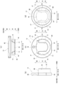
- FIG. 17(a) is a view of the bush taken out and seen from the right side of FIG. 4
- FIG. 17(b) is a view of the bush seen from the right side of FIG. 17(a)
- FIG. 17(c) is a view of the bush seen from the rear side of FIG. 17(a) (the left side of FIG. 4)
- FIG. 17(d) is a cross-sectional view taken along CC of FIG. 17(a).
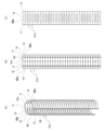
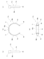
- FIG. 18 is a view of the elastic member taken out and viewed from the right side of FIG.
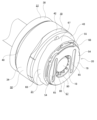
- the housing 16 has a wheel accommodating section 22 and a worm accommodating section 23 that is arranged in a twisted position relative to the wheel accommodating section 22 and whose axially intermediate section opens into the wheel accommodating section 22.
- a support bearing 32 is disposed between the large diameter cylindrical surface portion 31 of the worm 18 and the inner peripheral surface of the worm accommodating portion 23.
- the support bearing 32 is configured as a ball bearing. That is, the support bearing 32 has an inner ring 33 having an inner ring raceway on its outer peripheral surface, an outer ring 34 having an outer ring raceway on its inner peripheral surface, and a plurality of balls 35, each of which is a rolling element, disposed between the inner ring raceway and the outer ring raceway.
- the support bearing 32 can also be a rolling bearing such as a cylindrical roller bearing in which the rolling elements are cylindrical rollers or a tapered roller bearing in which the rolling elements are tapered rollers, or a sliding bearing.
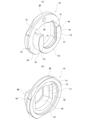
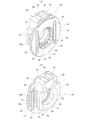
- the bush 36 has a stepped cylindrical shape.
- the bush 36 includes a small diameter cylindrical portion 75, a side plate portion 76 bent radially outward from the other end of the small diameter cylindrical portion 75 in the second direction, a large diameter cylindrical portion 77 bent radially outward from the radially outer end of the side plate portion 76, and an outward flange portion 78 bent radially outward from the other end of the large diameter cylindrical portion 77 in the second direction.
- the bush fitting hole portion 74 is provided to penetrate the center of the small diameter cylindrical portion 75 in the second direction.
- the two holder inclined surfaces 41 constituting the holder 19 are provided on the inner side surfaces 51, which are the sides of the two guide parts 49 facing each other in the third direction.
- each of the inner side surfaces 51 of the two guide parts 49 has a crank shape with a step surface (holder inclined surface 41) in the middle part in the second direction, as shown in FIG. 13 (c), when viewed from the first direction. That is, the two holder inclined surfaces 41 are provided on the middle part in the second direction of the inner side surfaces 51 of the two guide parts 49, more specifically, on one side part in the second direction of the middle part.
- the two holder inclined surfaces 41 are inclined in a direction approaching each other as they approach one side in the second direction.
- the base body 58 has two pressed parts 62 at the end farther from the worm wheel 17 in the first direction, and at both ends in the third direction of the other side portion in the second direction.
- Each of the two pressed parts 62 is formed by a partial cylindrical surface centered on the central axis of the through hole 56.
- the base body 58 has a pedestal surface portion 63 formed by a flat surface perpendicular to the first direction, at the end farther from the worm wheel 17 in the first direction, and between the two pressed parts 62 in the third direction.
- Each of the two arms 68 is configured to have a partially cylindrical shape.
- Each of the two arms 68 has a bent portion 69 that is bent radially outward from the tip.
- the tip part of the worm 18 is elastically biased toward the worm wheel 17 side, i.e., the side closer to the worm wheel 17 in the first direction, via the pad 20. This reduces backlash at the meshing area between the wheel teeth 24 and the worm teeth 25.
- the inclination angle of the holder inclined surface 41 with respect to the second direction and the inclination angle of the pad inclined surface 53 with respect to the second direction do not need to be strictly the same, and may differ within the range of manufacturing error.
- the inclination angle of the holder inclined surface 41 with respect to the second direction can also be slightly (for example, about 0.5°) smaller than the inclination angle of the pad inclined surface 53 with respect to the second direction. In this way, at the contact portion between the holder inclined surface 41 and the pad inclined surface 53, the tip end of the pad inclined surface 53 (the end on the right side in the third direction in FIG. 11, the end on the other side in the second direction in FIG. 11) comes into particularly strong surface contact with the holder inclined surface 41. As a result, the posture of the pad 20 with respect to the holder 19 becomes stable.
- the pad 20 is provided at multiple locations in the circumferential direction and has pad oil-retaining recesses 80 that open to the inner circumferential surface of one end of the pad fitting hole 61 in the second direction and to the pad step surface 81.
- This allows grease to be retained at the connection between the inner circumferential surface of the pad fitting hole 61 and the pad step surface 81.
- This allows the lubrication state of the area between the small diameter cylindrical surface portion 30 provided at the tip of the worm 18 and the inner circumferential surface of the pad fitting hole 61 to be maintained in a good condition for a long period of time, and the occurrence of damage such as wear in this area can be prevented for a long period of time.
- the durability of the worm reduction gear 14 can be ensured in a good condition.
- each pad oil-retaining recess 80 is open only to one end of the inner circumferential surface of the pad fitting hole 61 in the second direction. Therefore, with the worm reducer 14 of this example, the surface pressure of the sliding contact portion between the inner circumferential surface of the pad fitting hole 61 and the small diameter cylindrical surface portion 30 can be kept low compared to a structure in which each pad oil-retaining recess is formed over the entire length of the inner circumferential surface of the pad fitting hole in the second direction. From this perspective, it is also possible to prevent damage such as wear from occurring in the area between the inner circumferential surface of the pad fitting hole 61 and the small diameter cylindrical surface portion 30.
- each pad oil-retaining recess can also be formed over the entire length of the inner circumferential surface of the pad fitting hole in the second direction.
- the bush 36 has bush oil-retaining recesses 82 at multiple circumferential locations that open to the inner circumferential surface of the other end of the bush fitting hole 74 in the second direction and to the radially inner end of the side surface of the other side of the side plate 76 in the second direction. This allows grease to be retained at the connection between the inner circumferential surface of the bush fitting hole 74 and the other side surface of the side plate 76 in the second direction.
- the height in the second direction of at least one protrusion 64a, 64b provided on each of the two pad elastic pressure plates 54 increases continuously or in stages as it moves away from the worm 18 in the third direction.
- the height in the second direction of the protrusion 64a on the side farther from the worm 18 in the third direction is higher than the height in the second direction of the protrusion 64b on the side closer to the worm 18 in the third direction.
- the height in the second direction of the protrusion 64a on the side farther from the worm 18 in the third direction is made higher than the height in the second direction of the protrusion 64b on the side closer to the worm 18 in the third direction. Therefore, when the pad 20 is assembled to the protrusion 44 of the holder 19, the tips of the two protrusions 64a, 64b can be reliably abutted against the holder pressed surface 52. This makes it possible to stabilize the manner in which the pad elastic pressure plate 54 elastically deforms, and prevents the surface pressure at the contact points between the tips of the protrusions 64a, 64b and the holder pressed surface 52 from becoming excessive, thereby preventing wear at the contact points.
- grease can be held between the two protrusions 64a, 64b provided on each of the two pad elastic pressure plates 54 to lubricate the contact area between the tip ends of the protrusions 64a, 64b and the holder pressed surface 52.
- the lubricated state of the contact area between the tip ends of the protrusions 64a, 64b and the holder pressed surface 52 can be maintained in a good condition for a long period of time. From this perspective, wear can also be prevented from occurring at the contact area between the tip ends of the protrusions 64a, 64b and the holder pressed surface 52.
- the two pad elastic pressure plates 54 each have two protrusions 64a, 64b, but when implementing the worm reducers of the first and second aspects of the present disclosure, the number of protrusions on each of the two pad elastic pressure plates can be three or more, or can be one.
- the tip of the protrusion is configured with an inclined surface that is inclined in a direction toward the other side of the second direction the further it is from the worm in the third direction. This makes it possible to increase the contact area between the tip of the protrusion and the pressed surface of the holder, preventing the elastic deformation of the pad elastic pressure plate from becoming unstable and the tip of the protrusion from wearing out.
- a configuration with only a pad oil-retaining recess can be adopted.
- the bush 36 can be omitted, or a bush fitted to the outer ring 34 by a tight fit can be fitted inside the worm accommodating portion 23 with a radial gap therebetween.
- a configuration with only a bush oil-retaining recess can be adopted.
- the elastic member 21a is composed of a partially cut cylindrical (approximately C-shaped) leaf spring having a discontinuous portion 66 at one location in the circumferential direction.
- the elastic member 21a has a base portion 67a located on the side farther from the worm 18 in the first direction, and two arms 68a extending in the circumferential direction from both ends of the base portion 67a in the circumferential direction.
- the base 67a is composed of a flat plate perpendicular to the first direction.
- the base 67a has a constricted portion 70 in the middle in the third direction, which has a smaller width dimension in the second direction than both side portions in the third direction.
- the constricted portion 70 can be omitted.
- Each of the two arms 68a is configured in a partially cylindrical shape.
- each of the two arms 68a has, in order from the side closest to the base 67a in the circumferential direction, a base-side wide portion 71, a narrow portion 72, and a tip-side wide portion 73.
- each of the two arms 68a has a bent portion 69 that is bent radially outward from the tip of the tip-side wide portion 73.
- the width dimension of the bent portion 69 in the second direction is the same as the width dimension W73 of the tip-side wide portion 73 in the second direction.
- the bent portion 69 may be omitted.
- the elasticity of the elastic member 21a can be adjusted by adjusting the width dimension W68 in the second direction of the narrow portion 72 of the two arms 68a. That is, in the worm reducer of this example, the force with which the elastic member 21a elastically biases the tip of the worm 18 toward the worm wheel 17 via the pad 20 can be appropriately adjusted by adjusting the width dimension W72 in the second direction of the narrow portion 72. As a result, it is possible to suppress the occurrence of backlash at the meshing portion between the wheel teeth 24 and the worm teeth 25, suppress the occurrence of abnormal noise, and suppress unnecessary increases in friction at the meshing portion.
- the elastic member 21a can be easily handled. The reason for this will be explained with reference to Figs. 21(a) to 22(c) in addition to Figs. 19(a) to 20(c).
- Figures 21(a) to 22(c) show a comparative example to the second example.
- each of the two arms 68z constituting the elastic member 21z in order from the side closest to the base 67a in the circumferential direction, has only a base-side wide portion 71 and a narrow portion 72z, and does not have a tip-side wide portion 73.
- the elasticity of the elastic member 21z of the comparative example can also be adjusted by adjusting the width dimension in the second direction of the narrow portion 72z.
- the width dimension in the second direction of the narrow portion 72z is smaller than the width dimension in the second direction of the base-side wide portion 71. Therefore, when multiple elastic members 21z are stacked in the axial direction, they tend to tilt toward the discontinuous portion 66, as shown in Figures 22(a) to 22(c), making handling difficult.
- each of the two arms 68a constituting the elastic member 21a has a base-side wide portion 71 and a tip-side wide portion 73, which are adjacent to both circumferential sides of the narrow portion 72 and have the same width dimensions W71, W72 in the second direction. Therefore, as shown in Figures 20(a) to 20(c), even when multiple elastic members 21a are stacked in the axial direction, tilting can be prevented, and the elastic members 21a can be easily handled. This makes it easy to perform so-called rod-wrap packaging, in which multiple elastic members 21a are wrapped around the periphery while stacked in the axial direction. And/or, they can be easily set in a fixed arrangement device while stacked in the axial direction.
- the elastic member 21a has a base 67a formed from a flat plate, and the base 67a has a constricted portion 70 in the middle in the third direction.
- the phase alignment of the elastic member with respect to the holder can be performed by any method, such as displaying a mark.
- the base can be configured to be partially cylindrical and/or the constricted portion can be omitted.
Landscapes
- Engineering & Computer Science (AREA)
- General Engineering & Computer Science (AREA)
- Mechanical Engineering (AREA)
- Chemical & Material Sciences (AREA)
- Combustion & Propulsion (AREA)
- Transportation (AREA)
- Gear Transmission (AREA)
- Power Steering Mechanism (AREA)
- General Details Of Gearings (AREA)
Priority Applications (3)
| Application Number | Priority Date | Filing Date | Title |
|---|---|---|---|
| JP2024567862A JP7755083B2 (ja) | 2022-12-27 | 2023-12-26 | ウォーム減速機 |
| CN202380089643.5A CN120457291A (zh) | 2022-12-27 | 2023-12-26 | 蜗杆减速器 |
| EP23912147.8A EP4644728A1 (en) | 2022-12-27 | 2023-12-26 | Worm reducer |
Applications Claiming Priority (2)
| Application Number | Priority Date | Filing Date | Title |
|---|---|---|---|
| JP2022-209400 | 2022-12-27 | ||
| JP2022209400 | 2022-12-27 |
Publications (1)
| Publication Number | Publication Date |
|---|---|
| WO2024143368A1 true WO2024143368A1 (ja) | 2024-07-04 |
Family
ID=91718123
Family Applications (1)
| Application Number | Title | Priority Date | Filing Date |
|---|---|---|---|
| PCT/JP2023/046678 Ceased WO2024143368A1 (ja) | 2022-12-27 | 2023-12-26 | ウォーム減速機 |
Country Status (4)
| Country | Link |
|---|---|
| EP (1) | EP4644728A1 (https=) |
| JP (1) | JP7755083B2 (https=) |
| CN (1) | CN120457291A (https=) |
| WO (1) | WO2024143368A1 (https=) |
Citations (3)
| Publication number | Priority date | Publication date | Assignee | Title |
|---|---|---|---|---|
| JP2005042913A (ja) * | 2003-06-25 | 2005-02-17 | Nsk Ltd | ウォーム減速機及び電動式パワーステアリング装置 |
| JP4381024B2 (ja) | 2003-04-10 | 2009-12-09 | 日本精工株式会社 | 電動式パワーステアリング装置用アシスト装置及び電動式パワーステアリング装置 |
| JP2023004553A (ja) * | 2021-06-28 | 2023-01-17 | 日本精工株式会社 | ウォーム減速機 |
-
2023
- 2023-12-26 WO PCT/JP2023/046678 patent/WO2024143368A1/ja not_active Ceased
- 2023-12-26 CN CN202380089643.5A patent/CN120457291A/zh active Pending
- 2023-12-26 EP EP23912147.8A patent/EP4644728A1/en active Pending
- 2023-12-26 JP JP2024567862A patent/JP7755083B2/ja active Active
Patent Citations (3)
| Publication number | Priority date | Publication date | Assignee | Title |
|---|---|---|---|---|
| JP4381024B2 (ja) | 2003-04-10 | 2009-12-09 | 日本精工株式会社 | 電動式パワーステアリング装置用アシスト装置及び電動式パワーステアリング装置 |
| JP2005042913A (ja) * | 2003-06-25 | 2005-02-17 | Nsk Ltd | ウォーム減速機及び電動式パワーステアリング装置 |
| JP2023004553A (ja) * | 2021-06-28 | 2023-01-17 | 日本精工株式会社 | ウォーム減速機 |
Non-Patent Citations (1)
| Title |
|---|
| See also references of EP4644728A1 |
Also Published As
| Publication number | Publication date |
|---|---|
| JP7755083B2 (ja) | 2025-10-15 |
| JPWO2024143368A1 (https=) | 2024-07-04 |
| EP4644728A1 (en) | 2025-11-05 |
| CN120457291A (zh) | 2025-08-08 |
Similar Documents
| Publication | Publication Date | Title |
|---|---|---|
| JP5578237B2 (ja) | ラックアンドピニオン式ステアリングギヤユニット | |
| JP2021017930A (ja) | ウォーム減速機および電動アシスト装置 | |
| JP7495174B2 (ja) | ウォーム減速機 | |
| US11965582B2 (en) | Worm reducer and electric assist device | |
| JP2023004553A (ja) | ウォーム減速機 | |
| JP5163626B2 (ja) | 電動式パワーステアリング装置 | |
| JP7755083B2 (ja) | ウォーム減速機 | |
| WO2021241135A1 (ja) | ウォーム減速機および電動アシスト装置 | |
| JP5509795B2 (ja) | 電動式パワーステアリング装置 | |
| JP7812942B2 (ja) | ウォーム減速機およびその組立方法 | |
| JP7751753B2 (ja) | ウォーム減速機 | |
| JPWO2024135729A5 (https=) | ||
| JP7835909B2 (ja) | ウォーム減速機およびその組立方法 | |
| JP7673959B2 (ja) | ウォーム減速機 | |
| JP7501735B1 (ja) | シザーズギア | |
| JP5018361B2 (ja) | 電動式パワーステアリング装置 | |
| JP5309670B2 (ja) | 電動式パワーステアリング装置 | |
| US12473013B2 (en) | Steering force actuator | |
| WO2025041791A1 (ja) | ウォーム減速機 | |
| WO2024029451A1 (ja) | ウォーム減速機 | |
| WO2024029440A1 (ja) | ウォーム減速機 | |
| JP2019007539A (ja) | ウォーム減速機 |
Legal Events
| Date | Code | Title | Description |
|---|---|---|---|
| 121 | Ep: the epo has been informed by wipo that ep was designated in this application |
Ref document number: 23912147 Country of ref document: EP Kind code of ref document: A1 |
|
| WWE | Wipo information: entry into national phase |
Ref document number: 2024567862 Country of ref document: JP |
|
| WWE | Wipo information: entry into national phase |
Ref document number: 202380089643.5 Country of ref document: CN |
|
| WWE | Wipo information: entry into national phase |
Ref document number: 2023912147 Country of ref document: EP |
|
| NENP | Non-entry into the national phase |
Ref country code: DE |
|
| ENP | Entry into the national phase |
Ref document number: 2023912147 Country of ref document: EP Effective date: 20250728 |
|
| WWP | Wipo information: published in national office |
Ref document number: 202380089643.5 Country of ref document: CN |
|
| ENP | Entry into the national phase |
Ref document number: 2023912147 Country of ref document: EP Effective date: 20250728 |
|
| WWP | Wipo information: published in national office |
Ref document number: 2023912147 Country of ref document: EP |